EP1874635B1 - Automated operation application module, in particular for a packaging machine - Google Patents
Automated operation application module, in particular for a packaging machine Download PDFInfo
- Publication number
- EP1874635B1 EP1874635B1 EP06725577A EP06725577A EP1874635B1 EP 1874635 B1 EP1874635 B1 EP 1874635B1 EP 06725577 A EP06725577 A EP 06725577A EP 06725577 A EP06725577 A EP 06725577A EP 1874635 B1 EP1874635 B1 EP 1874635B1
- Authority
- EP
- European Patent Office
- Prior art keywords
- frame
- film
- packaging material
- sealing station
- application module
- Prior art date
- Legal status (The legal status is an assumption and is not a legal conclusion. Google has not performed a legal analysis and makes no representation as to the accuracy of the status listed.)
- Expired - Lifetime
Links
Images
Classifications
-
- B—PERFORMING OPERATIONS; TRANSPORTING
- B65—CONVEYING; PACKING; STORING; HANDLING THIN OR FILAMENTARY MATERIAL
- B65B—MACHINES, APPARATUS OR DEVICES FOR, OR METHODS OF, PACKAGING ARTICLES OR MATERIALS; UNPACKING
- B65B9/00—Enclosing successive articles, or quantities of material, e.g. liquids or semiliquids, in flat, folded, or tubular webs of flexible sheet material; Subdividing filled flexible tubes to form packages
- B65B9/10—Enclosing successive articles, or quantities of material, in preformed tubular webs, or in webs formed into tubes around filling nozzles, e.g. extruded tubular webs
- B65B9/20—Enclosing successive articles, or quantities of material, in preformed tubular webs, or in webs formed into tubes around filling nozzles, e.g. extruded tubular webs the webs being formed into tubes in situ around the filling nozzles
-
- B—PERFORMING OPERATIONS; TRANSPORTING
- B65—CONVEYING; PACKING; STORING; HANDLING THIN OR FILAMENTARY MATERIAL
- B65B—MACHINES, APPARATUS OR DEVICES FOR, OR METHODS OF, PACKAGING ARTICLES OR MATERIALS; UNPACKING
- B65B59/00—Arrangements to enable machines to handle articles of different sizes, to produce packages of different sizes, to vary the contents of packages, to handle different types of packaging material, or to give access for cleaning or maintenance purposes
- B65B59/04—Machines constructed with readily-detachable units or assemblies, e.g. to facilitate maintenance
-
- B—PERFORMING OPERATIONS; TRANSPORTING
- B65—CONVEYING; PACKING; STORING; HANDLING THIN OR FILAMENTARY MATERIAL
- B65B—MACHINES, APPARATUS OR DEVICES FOR, OR METHODS OF, PACKAGING ARTICLES OR MATERIALS; UNPACKING
- B65B61/00—Auxiliary devices, not otherwise provided for, for operating on sheets, blanks, webs, binding material, containers or packages
- B65B61/18—Auxiliary devices, not otherwise provided for, for operating on sheets, blanks, webs, binding material, containers or packages for making package-opening or unpacking elements
Definitions
- the invention is based on an independently operating application module, in particular for a packaging machine according to the preamble of the independent claim.
- application module in particular for a packaging machine according to the preamble of the independent claim.
- integrated in / add-on modules in intermittent tubular bag machines with extensive mechanical and electrical interfaces, which seal, for example, internal coffee degassing valves in films, from which the bag to be filled is produced in the same machine.
- manual manual workstations are known.
- a VFFS filler according to the preamble of claim 1 is already known for large bags.
- This machine comprises a holding device for carrying one or more feed rolls of a film material.
- a guide means is provided to support and feed a sheet of film from one of the feed rollers along a feed path.
- a film feed drive is provided to translate the film sheet along the feed path and through bag forming means where a portion of the film sheet is folded and wrapped around a drop tube.
- a vertical welder is provided to form a vertical weld along the folded foil sheet.
- a horizontal welder is provided to produce a bottom seal for a bag to be filled and a top seal for a filled bag.
- the independently operating application module according to the invention in particular for a packaging machine, comprises the features of the independent claim.
- the application of, for example, internal coffee valves is carried out without complicated mechanical and electrical intervention in a tubular bag machine / packaging system or film web.
- the operation of the downstream packaging machine may be intermittent or continuous. Due to the decoupling of the independently operating application module from the actual packaging machine, such as, for example, a tubular bag machine, high outputs can be achieved, which are, for example, 120 valve applications per minute.
- the line configuration is reduced to a minimum, since there are only a few and simple interfaces to downstream machines. For this reason Retrofitting existing packaging lines without degassing valves is also less risky, and on-site rebuild time is reduced relative to the integrated solution.
- the independently operating application module also serves to decouple the upstream and downstream process (intermittently or continuously). It has a separate control.
- the following packaging machine such as a tubular bag machine can be from any manufacturer, which reduces the configuration effort.
- a fully tested module can be provided during a retrofit.
- the independently operating application module can easily be used for other variants / applications such as ZIP closures or reclosures (to be glued or sealed to films).
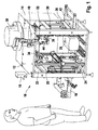
- FIG. 1 a perspective view of the independently operating application module according to the invention without showing the packaging material
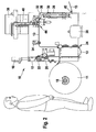
- FIG. 2 a side view with foil, but without frame
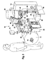
- FIG. 3 an isometric representation of in FIG. 2 shown arrangement.
- An independently operating application module 10 consists of a frame 12 with screwed-on control cabinet 14, integrated control and display terminal 16 and own protection.
- a packaging material roll suspension 18 and a cutting and gluing table 20 are decoupled from the existing packaging installation and fastened to the frame 12.
- the film leader 26 operates with a print mark controller 30. Between the film store 24 and the vacuum film leader 26, a servo motor driven sealing station 32 and a film cutting station 34 are accommodated.
- the sealing station 32 operates in the ultrasound process by means of an ultrasonic welding device 36.
- An electromagnetic vibratory conveyor 38 for sorting and feeding the objects not shown to be sealed in the sealing station 32 is placed on the cover plate of the frame 12.
- the signal exchange to the downstream machine takes place via potential-free contacts.
- the sealing station 32, the articles to be sealed are fed via a feed chute 40 from the vibratory conveyor 38.
- the sealing station 32 is preceded by a web edge control 44.
- the film 13, which is now provided with the sealed objects, leaves the independently operating application module 10 via a film extension 42, which is equipped, for example, with a rocker for maintaining the web tension.
- a separate control for the application module 10 is housed in a control cabinet 14 which is connected to the frame 12.
- the independently operating application module 10 is used in particular for the connection of internal coffee degassing valves with a packaging material 13 such as a film. These valves are supplied to the application module 10 via a vibratory conveyor 38.
- the packaging material 13 provided with the valves can subsequently be supplied to further packaging machines, such as, for example, tubular bag machines for producing and filling a coffee bag.
- the provision of an independently operating application module 10 simplifies the retrofitting of existing packaging machines and serves to decouple the upstream and downstream process. Like that Figures 2 and 3 If the end of a packaging material roll 11 is detected, the cutting and gluing table 20 serves to connect the outgoing film web to the beginning a new film web of a new packaging material roll 11. The film 13 is fed to the film storage 24 via the preliminary development 23.
- a so-called airbag film storage is suitable for application modules 10 with high performance.
- This per se known Folien acknowledgedart includes In addition, for example, via a photoelectric control and a vacuum brake to maintain the desired film tension. A chicane is used for clean film guidance.
- foil memory 24 can be achieved very short feed times. In principle, however, other types of known film storage 24 are conceivable. From the film storage 24, the film 13 passes to the film cutting station 34. The film 13 is cut at the point where later in the sealing station 32, the valve is sealed to the film is then the film is intermittently fed to the sealing station 32. By means of a positioning device, the valve is brought into the desired sealing position over the incision interface in the film 13.
- the valve is fed to a sealing die which is brought into a sealing position in the vertical direction becomes.
- sealing processes for example, thermal processes are used which, conventionally or via ultrasound, generate heat.
- an ultrasonic welding device 36 is used, which allows very short welding cycles. In principle, however, other methods are conceivable.
- the vacuum film leader 26 is, for example, driven by a servo motor and pulls the film 13 intermittently out of the film store 24. However, the intermittent film preference could also be generated in a manner other than by vacuum.
- the vacuum pump 28, which is also part of the application module, provides the required vacuum.
- valves instead of valves as objects to be sealed, also reclosures, ZIP-closures or the like can be applied, which are sealed / glued, or any other objects.
Landscapes
- Engineering & Computer Science (AREA)
- Mechanical Engineering (AREA)
- Containers And Plastic Fillers For Packaging (AREA)
- Auxiliary Devices For And Details Of Packaging Control (AREA)
- Basic Packing Technique (AREA)
Abstract
Description
Die Erfindung geht aus von einem eigenständig arbeitenden Applikationsmodul, insbesondere für eine Verpackungsmaschine nach der Gattung des unabhängigen Anspruchs. Es sind integrierte Ein-/Anbaumodule in intermittierenden Schlauchbeutelmaschinen mit umfangreichen mechanischen und elektrischen Schnittstellen bekannt, die beispielsweise innenliegende Kaffeeentgasungsventile in Folien einsiegeln, aus denen im Rahmen der selben Maschine auch der zu befüllende Beutel hergestellt wird. Weiterhin sind auch manuelle Handarbeitsplätze bekannt.The invention is based on an independently operating application module, in particular for a packaging machine according to the preamble of the independent claim. There are known integrated in / add-on modules in intermittent tubular bag machines with extensive mechanical and electrical interfaces, which seal, for example, internal coffee degassing valves in films, from which the bag to be filled is produced in the same machine. Furthermore, manual manual workstations are known.
Aus der
Das erfindungsgemäße eigenständig arbeitende Applikationsmodul, insbesondere für eine Verpackungsmaschine, umfasst die Merkmale des unabhängigen Anspruchs. Die Applizierung von beispielsweise innenliegenden Kaffeeventilen erfolgt ohne aufwändigen mechanischen und elektrischen Eingriff in eine Schlauchbeutelmaschine/Verpackungsanlage oder Folienbahn. Die Arbeitsweise der nachgeschalteten Verpackungsmaschine kann intermittierend oder kontinuierlich sein. Durch die Entkopplung des eigenständig arbeitenden Applikationsmoduls von der eigentlichen Verpackungsmaschine wie beispielsweise Schlauchbeutelmaschine können hohe Leistungen erzielt werden, die beispielsweise bei 120 Ventilapplikationen in der Minute liegen. Die Linienprojektierung wird auf ein Minimum reduziert, da es nur wenige und einfache Schnittstellen zu nachgelagerten Maschinen gibt. Aus diesem Grund ist auch die Nachrüstung von bereits installierten Verpackungslinien ohne Entgasungsventile mit weniger Risiko verbunden, und die Umbauzeit vor Ort wird im Verhältnis zur integrierten Lösung verkürzt. Mit diesem Modul können auch schnell laufende Schlauchbeutelmaschinen mit kontinuierlichem Folienvorzug innen liegende Kaffeeentgasungsventile verarbeiten. Das erfindungsgemäße eigenständig arbeitende Applikationsmodul dient zudem der Entkopplung des vor- und nachgelagerten Prozesses (intermittierend oder kontinuierlich). Es weißt eine separate Steuerung auf. Die nachfolgende Verpackungsmaschine wie beispielsweise eine Schlauchbeutelmaschine kann von einem beliebigen Hersteller sein, was den Projektierungsaufwand reduziert. Ein komplett erprobtes Modul kann bei einer Nachrüstung bereitgestellt werden. Zudem lässt sich das eigenständig arbeitende Applikationsmodul leicht für andere Varianten/Anwendungen wie beispielsweise ZIP-Verschlüsse oder Wiederverschlüsse (auf Folien zu kleben oder zu siegeln).The independently operating application module according to the invention, in particular for a packaging machine, comprises the features of the independent claim. The application of, for example, internal coffee valves is carried out without complicated mechanical and electrical intervention in a tubular bag machine / packaging system or film web. The operation of the downstream packaging machine may be intermittent or continuous. Due to the decoupling of the independently operating application module from the actual packaging machine, such as, for example, a tubular bag machine, high outputs can be achieved, which are, for example, 120 valve applications per minute. The line configuration is reduced to a minimum, since there are only a few and simple interfaces to downstream machines. For this reason Retrofitting existing packaging lines without degassing valves is also less risky, and on-site rebuild time is reduced relative to the integrated solution. With this module even high-speed tubular bag machines with continuous film preference can process internal coffee degassing valves. The independently operating application module according to the invention also serves to decouple the upstream and downstream process (intermittently or continuously). It has a separate control. The following packaging machine such as a tubular bag machine can be from any manufacturer, which reduces the configuration effort. A fully tested module can be provided during a retrofit. In addition, the independently operating application module can easily be used for other variants / applications such as ZIP closures or reclosures (to be glued or sealed to films).
Weitere Vorteile und vorteilhafte Weiterbildungen des erfindungsgemäßen eigenständig arbeitenden Applikationsmoduls ergeben sich aus den abhängigen Ansprüchen und aus der Beschreibung.Further advantages and advantageous developments of the independently operating application module according to the invention will become apparent from the dependent claims and from the description.
Ein Ausführungsbeispiel der Erfindung ist in der Zeichnung dargestellt und wird in der nachfolgenden Beschreibung näher erläutert. Es zeigen
die
the
Ein eigenständig arbeitendes Applikationsmodul 10 besteht aus einem Gestell 12 mit angeschraubtem Schaltschrank 14, integriertem Bedien- und Anzeigeterminal 16 und eigener Beschutzung. Eine Packstoffrollenaufhängung 18 und ein Schneide- und Klebetisch 20 wird von der bestehenden Verpackungsanlage entkoppelt und am Gestell 12 befestigt. Eine Vorabwicklung 22, die einen Packstoff 13 wie beispielsweise eine Folie kontinuierlich in einen Folienspeicher 24 einträgt, und ein servomotorisch angetriebener Vakuumfolienvorzug 26, der aus dem Folienspeicher 24 den Packstoff 13 intermittierend vorzieht, bilden den Packstoffvorzug. Für die genaue Platzierung des einzusiegelnden Gegenstands wie beispielsweise ein Ventil arbeitet der Folienvorzug 26 mit einer Druckmarkensteuerung 30. Zwischen Folienspeicher 24 und Vakuumfolienvorzug 26 sind eine servomotorisch angetriebene Siegelstation 32 und eine Folieneinschneidstation 34 untergebracht. Zur Reduzierung der Prozesszeit arbeitet die Siegelstation 32 im Ultraschallverfahren mittels einer Ultraschallschweißeinrichtung 36. Ein elektromagnetischer Schwingförderer 38 zur Sortierung und Zuführung der nicht dargestellten einzusiegelnden Gegenstände in die Siegelstation 32 ist auf der Deckplatte des Gestells 12 platziert. Der Signalaustausch zur nachgeschalteten Maschine erfolgt über potenzialfreie Kontakte. Der Siegelstation 32 werden die einzusiegelnden Gegenstände über eine Zuführrinne 40 vom Schwingförderer 38 zugeführt. Der Siegelstation 32 ist eine Bahnkantensteuerung 44 vorgeschaltet. Die nun mit den eingesiegelten Gegenständen versehene Folie 13 verlässt das eigenständig arbeitende Applikationsmodul 10 über eine Folienweiterführung 42, die beispielsweise mit einer Schwinge zur Aufrechterhaltung der Bahnspannung ausgestattet ist. Eine separate Steuerung für das Applikationsmodul 10 ist in einem Schaltschrank 14, der mit dem Gestell 12 verbunden ist, untergebracht.An independently
Das eigenständig arbeitende Applikationsmodul 10 dient insbesondere für die Verbindung von innen liegenden Kaffeeentgasungsventilen mit einem Verpackungsmaterial 13 wie beispielsweise eine Folie. Diese Ventile werden über einen Schwingförderer 38 dem Applikationsmodul 10 zugeführt. Der mit den Ventilen versehene Packstoff 13 kann anschließend weiteren Verpackungsmaschinen zugeführt werden wie beispielsweise Schlauchbeutelmaschinen zur Herstellung und Abfüllung eines Kaffeebeutels. Das Vorsehen eines eigenständig arbeitenden Applikationsmoduls 10 vereinfacht das Nachrüsten von bestehenden Verpackungsmaschinen und dient der Entkopplung des vor- und nachgelagerten Prozesses. Wie den
Anstelle von Ventilen als einzusiegelnde Gegenstände können auch Wiederverschlüsse, ZIP-Verschlüsse oder dergleichen appliziert werden, welche gesiegelt/geklebt werden, oder aber beliebige andere Gegenstände.Instead of valves as objects to be sealed, also reclosures, ZIP-closures or the like can be applied, which are sealed / glued, or any other objects.
Claims (9)
- Automated operation application module, in particular for a packaging machine,
with a frame (12),
with a suspension means (18) for rolls of packaging material, connected to the frame (12),
with a pre-unwinding unit (22) for supplying packaging material (13) to the film storage unit (24),
with a film storage unit (34), connected to the frame (12),
with a sealing station (32), connected to the frame (12),
with a film forwarding unit (42), connected to the frame (12), for forwarding the processed packaging material (13) to a packaging machine,
characterized in that
a vacuum film pre-drawing unit (26), connected to the frame (12), for supplying the packaging material (13) to the sealing station (13)
and a vacuum pump (28) for providing the required vacuum for the vacuum film pre-drawing unit (26) are provided. - Apparatus according to Claim 1, characterized in that a cutting and gluing table (20) is disposed in the frame (12).
- Apparatus according to one of the preceding claims, characterized in that a film notching station (34), connected to the frame (12), is provided.
- Apparatus according to one of the preceding claims, characterized in that a vibratory conveyor (38) is connected to the frame (12) for supplying items to be sealed to the sealing station (32).
- Apparatus according to one of the preceding claims, characterized in that a film storage unit (24) based on the airbag principle is provided.
- Apparatus according to one of the preceding claims, characterized in that the sealing station (32) has an ultrasound sealer (36).
- Apparatus according to one of the preceding claims, characterized in that an operator input and display terminal (16) is connected to the frame (12).
- Apparatus according to one of the preceding claims, characterized in that a supply channel (40) which connects the vibratory conveyor (38) to the sealing station (32) is provided.
- Apparatus according to one of the preceding claims, characterized in that a printed mark controller (30) is connected to the frame (12) for controlling the film pre-drawing unit (26).
Applications Claiming Priority (2)
| Application Number | Priority Date | Filing Date | Title |
|---|---|---|---|
| DE102005018407A DE102005018407A1 (en) | 2005-04-20 | 2005-04-20 | Independently operating application module, in particular for a packaging machine |
| PCT/EP2006/061347 WO2006111473A1 (en) | 2005-04-20 | 2006-04-05 | Automated operation application module, in particular for a packaging machine |
Publications (2)
| Publication Number | Publication Date |
|---|---|
| EP1874635A1 EP1874635A1 (en) | 2008-01-09 |
| EP1874635B1 true EP1874635B1 (en) | 2010-06-30 |
Family
ID=36520810
Family Applications (1)
| Application Number | Title | Priority Date | Filing Date |
|---|---|---|---|
| EP06725577A Expired - Lifetime EP1874635B1 (en) | 2005-04-20 | 2006-04-05 | Automated operation application module, in particular for a packaging machine |
Country Status (6)
| Country | Link |
|---|---|
| US (1) | US7775019B2 (en) |
| EP (1) | EP1874635B1 (en) |
| AT (1) | ATE472478T1 (en) |
| DE (2) | DE102005018407A1 (en) |
| ES (1) | ES2346557T3 (en) |
| WO (1) | WO2006111473A1 (en) |
Families Citing this family (3)
| Publication number | Priority date | Publication date | Assignee | Title |
|---|---|---|---|---|
| NL1035429C2 (en) * | 2008-05-16 | 2009-11-17 | Pmb Uva Internat B V | Device for packaging products in a foil package. |
| US8631555B1 (en) * | 2013-03-26 | 2014-01-21 | Dennis Favale | Sealing shrink wrap machine |
| US10314319B2 (en) * | 2013-11-20 | 2019-06-11 | 2266170 Ontario Inc. | Method and apparatus for accelerated or controlled degassing of roasted coffee |
Family Cites Families (31)
| Publication number | Priority date | Publication date | Assignee | Title |
|---|---|---|---|---|
| US3374602A (en) * | 1965-08-18 | 1968-03-26 | Mahaffy & Harder Eng Co | Indicia registration method and apparatus |
| US3432087A (en) * | 1966-09-01 | 1969-03-11 | Alfred P Costello | Package valve |
| US4000846A (en) * | 1975-06-30 | 1977-01-04 | Dunkin' Donuts Incorporated | Pressure relief valve and bag incorporating same |
| DE2537317A1 (en) * | 1975-08-21 | 1977-02-24 | Hesser Ag Maschf | PRESSURE COMPENSATING VALVE FOR A PACKAGING CONTAINER |
| US3992854A (en) * | 1976-02-18 | 1976-11-23 | The Kartridg Pak Co. | Method and apparatus for making dual compartment package |
| US4083737A (en) * | 1976-04-19 | 1978-04-11 | Eastman Kodak Company | Method and apparatus for attaching a strip of material transversely of a moving web |
| US4262470A (en) * | 1978-10-30 | 1981-04-21 | Sigma Systems, Inc. | Packaging system with cantilevered web feed system accessible for changing web |
| AU559751B2 (en) * | 1982-10-18 | 1987-03-19 | Unitika Ltd. | Filling bags with cap bodies |
| US4548018A (en) * | 1984-06-29 | 1985-10-22 | John Wojnicki | Apparatus for horizontally forming, filling and sealing film pouch material |
| US4568321A (en) * | 1984-08-22 | 1986-02-04 | Gaubert R J | Apparatus and method for making bags from flexible film material |
| DE3532839A1 (en) * | 1985-09-14 | 1987-03-26 | Overbeck Gmbh & Co | METHOD FOR ATTACHING DRINKING STRAWS TO PACKAGING CONTAINERS, AND APPARATUS FOR CARRYING OUT THE METHOD |
| GB8902320D0 (en) * | 1989-02-02 | 1989-03-22 | Du Pont Canada | Detucker for vertical form and fill machine |
| US4995936A (en) * | 1989-07-27 | 1991-02-26 | Robert Cohn | Continuous web splicing machine |
| IT1240311B (en) * | 1989-12-29 | 1993-12-07 | Cavanna Spa | PROCEDURE TO CHECK THE ADVANCE OF THE WINDING FILM IN WRAPPING MACHINES AND RELATED WRAPPING MACHINE |
| DE4008097A1 (en) * | 1990-03-14 | 1991-09-19 | Bosch Gmbh Robert | METHOD AND DEVICE FOR SEALING A PACKAGING CONTAINER PRESSURE VALVE |
| US5117608A (en) * | 1991-04-10 | 1992-06-02 | R. A. Jones & Co. Inc. | Pouch profile detector |
| US5277741A (en) * | 1992-08-06 | 1994-01-11 | Bartlett Tool And Manufacturing, Inc. | Sealing apparatus |
| DE4243020A1 (en) * | 1992-12-18 | 1994-06-30 | Bosch Gmbh Robert | Pressure relief valve for packaging containers |
| US5716471A (en) * | 1995-10-30 | 1998-02-10 | Elopak Systems Ag | Method for securing articles to laminates |
| US5715656A (en) * | 1996-02-05 | 1998-02-10 | Triangle Package Machinery Corporation | Form, fill and seal machine |
| GB9626696D0 (en) * | 1996-12-23 | 1997-02-12 | Ishida Seisakusho | Method of printing film at form-fill-seal packaging machine form-fill-seal packaging machine using the method |
| JP3808588B2 (en) * | 1997-05-30 | 2006-08-16 | 四国化工機株式会社 | Packaging container manufacturing apparatus and packaging container manufacturing method |
| DE19825064A1 (en) * | 1998-06-04 | 1999-12-09 | Indag Gmbh & Co Betriebs Kg | Device and method for welding foil material |
| US6182426B1 (en) * | 1998-10-19 | 2001-02-06 | Liqui-Box Corporation | Vertical form, fill, seal machine and methods |
| DE19910485C2 (en) * | 1999-03-10 | 2002-10-02 | Hassia Verpackung Ag | Aseptic tubular packaging machine |
| US6213645B1 (en) * | 2000-03-14 | 2001-04-10 | Fres-Co System Usa, Inc. | Flexible package with sealed edges and easy to open mouth |
| NL1016524C2 (en) * | 2000-11-01 | 2002-05-07 | Aquarius Bv | Forming, filling and closing machine. |
| US6718735B2 (en) * | 2002-03-19 | 2004-04-13 | Baxter International Inc. | Albumin in a flexible polymeric container |
| US6826892B2 (en) * | 2003-01-09 | 2004-12-07 | Glopak Inc. | Vertical form, fill and seal machine for handling large pouches |
| AU2003903509A0 (en) * | 2003-07-08 | 2003-07-24 | Tna Australia Pty Limited | A packaging machine former support |
| US7328543B2 (en) * | 2006-05-17 | 2008-02-12 | Plitek, L.L.C. | Apparatus and method for the application of pressure relief valves |
-
2005
- 2005-04-20 DE DE102005018407A patent/DE102005018407A1/en not_active Withdrawn
-
2006
- 2006-04-05 DE DE502006007328T patent/DE502006007328D1/en not_active Expired - Lifetime
- 2006-04-05 EP EP06725577A patent/EP1874635B1/en not_active Expired - Lifetime
- 2006-04-05 US US11/912,222 patent/US7775019B2/en active Active
- 2006-04-05 ES ES06725577T patent/ES2346557T3/en not_active Expired - Lifetime
- 2006-04-05 AT AT06725577T patent/ATE472478T1/en active
- 2006-04-05 WO PCT/EP2006/061347 patent/WO2006111473A1/en not_active Ceased
Also Published As
| Publication number | Publication date |
|---|---|
| DE502006007328D1 (en) | 2010-08-12 |
| ES2346557T3 (en) | 2010-10-18 |
| US20090217623A1 (en) | 2009-09-03 |
| US7775019B2 (en) | 2010-08-17 |
| DE102005018407A1 (en) | 2006-10-26 |
| WO2006111473A1 (en) | 2006-10-26 |
| EP1874635A1 (en) | 2008-01-09 |
| ATE472478T1 (en) | 2010-07-15 |
Similar Documents
| Publication | Publication Date | Title |
|---|---|---|
| EP2551203B1 (en) | Method for cutting packages | |
| DE19824797B4 (en) | Bag manufacturing apparatus and method for manufacturing foil bags | |
| EP3551446B1 (en) | Bag production device and method | |
| DE3515846A1 (en) | METHOD AND ARRANGEMENT FOR CONTROLLING A PACKING MACHINE | |
| EP0718096A2 (en) | Method and apparatus for making a beverage container | |
| DE19913408A1 (en) | Plastic tube for producing gas-filled packing material consists of two sheets sealed together along their edges with transverse spot-welds forming inflatable pockets and line of perforations each pair of spot-welded lines | |
| DE19941431A1 (en) | Plastic bag production, filling and grouping process in which a suspension strip is attached to a filled bag while welding the transverse base seam | |
| AT500126B1 (en) | METHOD FOR REPLACING TUBE ROLLERS, ESPECIALLY FOR SIDE HOLDING HOSES | |
| EP2812174A1 (en) | Method and device for making tubular bags of thin plastic films by means of an ultrasound welding process | |
| EP1874635B1 (en) | Automated operation application module, in particular for a packaging machine | |
| DE60302795T2 (en) | METHOD AND DEVICE FOR PRODUCING A TUBULAR PACKAGING | |
| DE2345151A1 (en) | Packing stacked thermoplastic film bags - by feeding into welded film containers and sealing | |
| EP1623926B1 (en) | Method and machine for producing and filling bags | |
| DE202015009407U1 (en) | Device for sealing a packaging or packaging material | |
| DE4310376B4 (en) | Automatic packaging machine with horizontal drain | |
| DE10251072A1 (en) | Form shoulder for forming a film web | |
| AT413378B (en) | Joining tail end of flat-wound tubular film to starting end of fresh roll, e.g. for packaging machines, involves slitting sides to form attachment tongues | |
| EP1818263B1 (en) | Method for packaging of goods and its use in a corresponding machine | |
| DE202004021466U1 (en) | Device for producing and filling bags | |
| DE102005018405B4 (en) | Drive device for a sealing station | |
| EP1874662B1 (en) | Flexible object supply channel | |
| DE10326320B4 (en) | Apparatus and method for making pouches | |
| EP3889053A1 (en) | Deep drawing packaging machine with space-saving film source | |
| EP3715266A1 (en) | Film packaging machine and method for packaging a packed product | |
| EP4452618A2 (en) | Method and device for producing bags |
Legal Events
| Date | Code | Title | Description |
|---|---|---|---|
| PUAI | Public reference made under article 153(3) epc to a published international application that has entered the european phase |
Free format text: ORIGINAL CODE: 0009012 |
|
| 17P | Request for examination filed |
Effective date: 20071120 |
|
| AK | Designated contracting states |
Kind code of ref document: A1 Designated state(s): AT BE BG CH CY CZ DE DK EE ES FI FR GB GR HU IE IS IT LI LT LU LV MC NL PL PT RO SE SI SK TR |
|
| DAX | Request for extension of the european patent (deleted) | ||
| 17Q | First examination report despatched |
Effective date: 20081119 |
|
| GRAP | Despatch of communication of intention to grant a patent |
Free format text: ORIGINAL CODE: EPIDOSNIGR1 |
|
| GRAS | Grant fee paid |
Free format text: ORIGINAL CODE: EPIDOSNIGR3 |
|
| GRAA | (expected) grant |
Free format text: ORIGINAL CODE: 0009210 |
|
| AK | Designated contracting states |
Kind code of ref document: B1 Designated state(s): AT BE BG CH CY CZ DE DK EE ES FI FR GB GR HU IE IS IT LI LT LU LV MC NL PL PT RO SE SI SK TR |
|
| REG | Reference to a national code |
Ref country code: CH Ref legal event code: EP Ref country code: GB Ref legal event code: FG4D Free format text: NOT ENGLISH |
|
| REG | Reference to a national code |
Ref country code: IE Ref legal event code: FG4D Free format text: LANGUAGE OF EP DOCUMENT: GERMAN |
|
| REF | Corresponds to: |
Ref document number: 502006007328 Country of ref document: DE Date of ref document: 20100812 Kind code of ref document: P |
|
| REG | Reference to a national code |
Ref country code: NL Ref legal event code: T3 |
|
| REG | Reference to a national code |
Ref country code: ES Ref legal event code: FG2A Ref document number: 2346557 Country of ref document: ES Kind code of ref document: T3 |
|
| PG25 | Lapsed in a contracting state [announced via postgrant information from national office to epo] |
Ref country code: LT Free format text: LAPSE BECAUSE OF FAILURE TO SUBMIT A TRANSLATION OF THE DESCRIPTION OR TO PAY THE FEE WITHIN THE PRESCRIBED TIME-LIMIT Effective date: 20100630 Ref country code: SE Free format text: LAPSE BECAUSE OF FAILURE TO SUBMIT A TRANSLATION OF THE DESCRIPTION OR TO PAY THE FEE WITHIN THE PRESCRIBED TIME-LIMIT Effective date: 20100630 |
|
| LTIE | Lt: invalidation of european patent or patent extension |
Effective date: 20100630 |
|
| PG25 | Lapsed in a contracting state [announced via postgrant information from national office to epo] |
Ref country code: FI Free format text: LAPSE BECAUSE OF FAILURE TO SUBMIT A TRANSLATION OF THE DESCRIPTION OR TO PAY THE FEE WITHIN THE PRESCRIBED TIME-LIMIT Effective date: 20100630 Ref country code: LV Free format text: LAPSE BECAUSE OF FAILURE TO SUBMIT A TRANSLATION OF THE DESCRIPTION OR TO PAY THE FEE WITHIN THE PRESCRIBED TIME-LIMIT Effective date: 20100630 Ref country code: SI Free format text: LAPSE BECAUSE OF FAILURE TO SUBMIT A TRANSLATION OF THE DESCRIPTION OR TO PAY THE FEE WITHIN THE PRESCRIBED TIME-LIMIT Effective date: 20100630 |
|
| PG25 | Lapsed in a contracting state [announced via postgrant information from national office to epo] |
Ref country code: PL Free format text: LAPSE BECAUSE OF FAILURE TO SUBMIT A TRANSLATION OF THE DESCRIPTION OR TO PAY THE FEE WITHIN THE PRESCRIBED TIME-LIMIT Effective date: 20100630 Ref country code: GR Free format text: LAPSE BECAUSE OF FAILURE TO SUBMIT A TRANSLATION OF THE DESCRIPTION OR TO PAY THE FEE WITHIN THE PRESCRIBED TIME-LIMIT Effective date: 20101001 |
|
| PG25 | Lapsed in a contracting state [announced via postgrant information from national office to epo] |
Ref country code: EE Free format text: LAPSE BECAUSE OF FAILURE TO SUBMIT A TRANSLATION OF THE DESCRIPTION OR TO PAY THE FEE WITHIN THE PRESCRIBED TIME-LIMIT Effective date: 20100630 |
|
| REG | Reference to a national code |
Ref country code: IE Ref legal event code: FD4D |
|
| PG25 | Lapsed in a contracting state [announced via postgrant information from national office to epo] |
Ref country code: PT Free format text: LAPSE BECAUSE OF FAILURE TO SUBMIT A TRANSLATION OF THE DESCRIPTION OR TO PAY THE FEE WITHIN THE PRESCRIBED TIME-LIMIT Effective date: 20101102 Ref country code: CY Free format text: LAPSE BECAUSE OF FAILURE TO SUBMIT A TRANSLATION OF THE DESCRIPTION OR TO PAY THE FEE WITHIN THE PRESCRIBED TIME-LIMIT Effective date: 20100630 Ref country code: RO Free format text: LAPSE BECAUSE OF FAILURE TO SUBMIT A TRANSLATION OF THE DESCRIPTION OR TO PAY THE FEE WITHIN THE PRESCRIBED TIME-LIMIT Effective date: 20100630 Ref country code: IS Free format text: LAPSE BECAUSE OF FAILURE TO SUBMIT A TRANSLATION OF THE DESCRIPTION OR TO PAY THE FEE WITHIN THE PRESCRIBED TIME-LIMIT Effective date: 20101030 Ref country code: SK Free format text: LAPSE BECAUSE OF FAILURE TO SUBMIT A TRANSLATION OF THE DESCRIPTION OR TO PAY THE FEE WITHIN THE PRESCRIBED TIME-LIMIT Effective date: 20100630 |
|
| PG25 | Lapsed in a contracting state [announced via postgrant information from national office to epo] |
Ref country code: IE Free format text: LAPSE BECAUSE OF FAILURE TO SUBMIT A TRANSLATION OF THE DESCRIPTION OR TO PAY THE FEE WITHIN THE PRESCRIBED TIME-LIMIT Effective date: 20100630 Ref country code: DK Free format text: LAPSE BECAUSE OF FAILURE TO SUBMIT A TRANSLATION OF THE DESCRIPTION OR TO PAY THE FEE WITHIN THE PRESCRIBED TIME-LIMIT Effective date: 20100630 |
|
| PLBE | No opposition filed within time limit |
Free format text: ORIGINAL CODE: 0009261 |
|
| STAA | Information on the status of an ep patent application or granted ep patent |
Free format text: STATUS: NO OPPOSITION FILED WITHIN TIME LIMIT |
|
| 26N | No opposition filed |
Effective date: 20110331 |
|
| REG | Reference to a national code |
Ref country code: DE Ref legal event code: R097 Ref document number: 502006007328 Country of ref document: DE Effective date: 20110330 |
|
| PG25 | Lapsed in a contracting state [announced via postgrant information from national office to epo] |
Ref country code: MC Free format text: LAPSE BECAUSE OF NON-PAYMENT OF DUE FEES Effective date: 20110430 |
|
| REG | Reference to a national code |
Ref country code: CH Ref legal event code: PL |
|
| GBPC | Gb: european patent ceased through non-payment of renewal fee |
Effective date: 20110405 |
|
| REG | Reference to a national code |
Ref country code: FR Ref legal event code: ST Effective date: 20111230 |
|
| PG25 | Lapsed in a contracting state [announced via postgrant information from national office to epo] |
Ref country code: FR Free format text: LAPSE BECAUSE OF NON-PAYMENT OF DUE FEES Effective date: 20110502 Ref country code: CH Free format text: LAPSE BECAUSE OF NON-PAYMENT OF DUE FEES Effective date: 20110430 Ref country code: LI Free format text: LAPSE BECAUSE OF NON-PAYMENT OF DUE FEES Effective date: 20110430 |
|
| PG25 | Lapsed in a contracting state [announced via postgrant information from national office to epo] |
Ref country code: GB Free format text: LAPSE BECAUSE OF NON-PAYMENT OF DUE FEES Effective date: 20110405 |
|
| REG | Reference to a national code |
Ref country code: AT Ref legal event code: MM01 Ref document number: 472478 Country of ref document: AT Kind code of ref document: T Effective date: 20110405 |
|
| PG25 | Lapsed in a contracting state [announced via postgrant information from national office to epo] |
Ref country code: AT Free format text: LAPSE BECAUSE OF NON-PAYMENT OF DUE FEES Effective date: 20110405 |
|
| PG25 | Lapsed in a contracting state [announced via postgrant information from national office to epo] |
Ref country code: LU Free format text: LAPSE BECAUSE OF NON-PAYMENT OF DUE FEES Effective date: 20110405 |
|
| PG25 | Lapsed in a contracting state [announced via postgrant information from national office to epo] |
Ref country code: TR Free format text: LAPSE BECAUSE OF FAILURE TO SUBMIT A TRANSLATION OF THE DESCRIPTION OR TO PAY THE FEE WITHIN THE PRESCRIBED TIME-LIMIT Effective date: 20100630 Ref country code: BG Free format text: LAPSE BECAUSE OF FAILURE TO SUBMIT A TRANSLATION OF THE DESCRIPTION OR TO PAY THE FEE WITHIN THE PRESCRIBED TIME-LIMIT Effective date: 20100930 |
|
| PG25 | Lapsed in a contracting state [announced via postgrant information from national office to epo] |
Ref country code: HU Free format text: LAPSE BECAUSE OF FAILURE TO SUBMIT A TRANSLATION OF THE DESCRIPTION OR TO PAY THE FEE WITHIN THE PRESCRIBED TIME-LIMIT Effective date: 20100630 |
|
| PGFP | Annual fee paid to national office [announced via postgrant information from national office to epo] |
Ref country code: ES Payment date: 20140417 Year of fee payment: 9 |
|
| PGFP | Annual fee paid to national office [announced via postgrant information from national office to epo] |
Ref country code: BE Payment date: 20140417 Year of fee payment: 9 |
|
| REG | Reference to a national code |
Ref country code: ES Ref legal event code: FD2A Effective date: 20160526 |
|
| PG25 | Lapsed in a contracting state [announced via postgrant information from national office to epo] |
Ref country code: ES Free format text: LAPSE BECAUSE OF NON-PAYMENT OF DUE FEES Effective date: 20150406 |
|
| PG25 | Lapsed in a contracting state [announced via postgrant information from national office to epo] |
Ref country code: BE Free format text: LAPSE BECAUSE OF NON-PAYMENT OF DUE FEES Effective date: 20150430 |
|
| PGFP | Annual fee paid to national office [announced via postgrant information from national office to epo] |
Ref country code: CZ Payment date: 20180323 Year of fee payment: 13 |
|
| PGFP | Annual fee paid to national office [announced via postgrant information from national office to epo] |
Ref country code: NL Payment date: 20180423 Year of fee payment: 13 |
|
| PG25 | Lapsed in a contracting state [announced via postgrant information from national office to epo] |
Ref country code: CZ Free format text: LAPSE BECAUSE OF NON-PAYMENT OF DUE FEES Effective date: 20190405 |
|
| PGFP | Annual fee paid to national office [announced via postgrant information from national office to epo] |
Ref country code: DE Payment date: 20190627 Year of fee payment: 14 |
|
| REG | Reference to a national code |
Ref country code: NL Ref legal event code: MM Effective date: 20190501 |
|
| PG25 | Lapsed in a contracting state [announced via postgrant information from national office to epo] |
Ref country code: NL Free format text: LAPSE BECAUSE OF NON-PAYMENT OF DUE FEES Effective date: 20190501 |
|
| REG | Reference to a national code |
Ref country code: DE Ref legal event code: R082 Ref document number: 502006007328 Country of ref document: DE Representative=s name: DAUB, THOMAS, DIPL.-ING., DE Ref country code: DE Ref legal event code: R081 Ref document number: 502006007328 Country of ref document: DE Owner name: SYNTEGON TECHNOLOGY GMBH, DE Free format text: FORMER OWNER: ROBERT BOSCH GMBH, 70469 STUTTGART, DE |
|
| PGFP | Annual fee paid to national office [announced via postgrant information from national office to epo] |
Ref country code: IT Payment date: 20200423 Year of fee payment: 15 |
|
| REG | Reference to a national code |
Ref country code: DE Ref legal event code: R119 Ref document number: 502006007328 Country of ref document: DE |
|
| PG25 | Lapsed in a contracting state [announced via postgrant information from national office to epo] |
Ref country code: DE Free format text: LAPSE BECAUSE OF NON-PAYMENT OF DUE FEES Effective date: 20201103 |
|
| PG25 | Lapsed in a contracting state [announced via postgrant information from national office to epo] |
Ref country code: IT Free format text: LAPSE BECAUSE OF NON-PAYMENT OF DUE FEES Effective date: 20200405 |
|
| PG25 | Lapsed in a contracting state [announced via postgrant information from national office to epo] |
Ref country code: IT Free format text: LAPSE BECAUSE OF NON-PAYMENT OF DUE FEES Effective date: 20210405 |