EP1874081A2 - Loudspeaker enclosure and loudspeaker system - Google Patents
Loudspeaker enclosure and loudspeaker system Download PDFInfo
- Publication number
- EP1874081A2 EP1874081A2 EP07012841A EP07012841A EP1874081A2 EP 1874081 A2 EP1874081 A2 EP 1874081A2 EP 07012841 A EP07012841 A EP 07012841A EP 07012841 A EP07012841 A EP 07012841A EP 1874081 A2 EP1874081 A2 EP 1874081A2
- Authority
- EP
- European Patent Office
- Prior art keywords
- sound wave
- loudspeaker
- guiding portion
- opening portion
- wave guiding
- Prior art date
- Legal status (The legal status is an assumption and is not a legal conclusion. Google has not performed a legal analysis and makes no representation as to the accuracy of the status listed.)
- Withdrawn
Links
Images




Classifications
-
- H—ELECTRICITY
- H04—ELECTRIC COMMUNICATION TECHNIQUE
- H04R—LOUDSPEAKERS, MICROPHONES, GRAMOPHONE PICK-UPS OR LIKE ACOUSTIC ELECTROMECHANICAL TRANSDUCERS; ELECTRIC HEARING AIDS; PUBLIC ADDRESS SYSTEMS
- H04R1/00—Details of transducers, loudspeakers or microphones
- H04R1/20—Arrangements for obtaining desired frequency or directional characteristics
- H04R1/32—Arrangements for obtaining desired frequency or directional characteristics for obtaining desired directional characteristic only
- H04R1/34—Arrangements for obtaining desired frequency or directional characteristics for obtaining desired directional characteristic only by using a single transducer with sound reflecting, diffracting, directing or guiding means
- H04R1/345—Arrangements for obtaining desired frequency or directional characteristics for obtaining desired directional characteristic only by using a single transducer with sound reflecting, diffracting, directing or guiding means for loudspeakers
- H04R1/347—Arrangements for obtaining desired frequency or directional characteristics for obtaining desired directional characteristic only by using a single transducer with sound reflecting, diffracting, directing or guiding means for loudspeakers for obtaining a phase-shift between the front and back acoustic wave
-
- H—ELECTRICITY
- H04—ELECTRIC COMMUNICATION TECHNIQUE
- H04R—LOUDSPEAKERS, MICROPHONES, GRAMOPHONE PICK-UPS OR LIKE ACOUSTIC ELECTROMECHANICAL TRANSDUCERS; ELECTRIC HEARING AIDS; PUBLIC ADDRESS SYSTEMS
- H04R1/00—Details of transducers, loudspeakers or microphones
- H04R1/02—Casings; Cabinets ; Supports therefor; Mountings therein
- H04R1/028—Casings; Cabinets ; Supports therefor; Mountings therein associated with devices performing functions other than acoustics, e.g. electric candles
Definitions
- the present invention relates to a loudspeaker enclosure and a loudspeaker system capable of improving a directivity of a loudspeaker.
- the loudspeaker array As the loudspeaker system capable of enhancing the directivity, i.e., the loudspeaker system having the so-called narrow directivity, there is the loudspeaker array, for example.
- the loudspeaker array enhances the directivity by controlling respective amplitudes and phases in individual loudspeakers.
- the system using the loudspeaker array tends to increase in size because a plurality of loudspeakers are used, however, for example, in JP-A-2006-101464 , such a technology is disclosed that, because a hood is fitted in front of a loudspeaker and also the loudspeaker is arranged at a focal point of a sound reflecting inner wall of the hood, the directivity can be enhanced even in a small-sized loudspeaker.
- the loudspeaker with the hood can enhance the directivity even in the small-sized loudspeaker, nevertheless such loudspeaker has the problem the directivity is deteriorated because a sound diffracts at an edge portion of an opening portion of the hood.
- JP-A-2006-101464 in order to solve this problem, the technology of providing a glass wool having a sound absorbing function along the edge portion of the opening portion of the hood is disclosed.
- a size of the loudspeaker is increased.
- a sound emitted from a rear surface of a diaphragm of the loudspeaker is forcedly attenuated by using the glass wool not to leak. Therefore, such arrangement similarly constitutes a factor that increases a size of the loudspeaker.
- the present invention has been made in view of the above circumstances, and it is an object of the present invention to provide a loudspeaker enclosure and a loudspeaker system capable of reducing a size and improving a directivity.
- the present invention provides a loudspeaker enclosure, comprising:
- the present invention provides a loudspeaker system, comprising:
- the first space is separated by one faces of diaphragms of a plurality of loudspeakers.
- the second space is separated by the other faces of the diaphragms of the loudspeakers.
- At least one of the first sound wave guiding portion and the second sound wave guiding portion has a light source.
- at least one of the first sound wave guiding portion and the second sound wave guiding portion is formed of light transmitting material.
- the loudspeaker has an acoustic lens.
- the first sound wave emitted from the first opening portion through the first sound wave guiding portion is opposite in phase to the second sound wave emitted from the second opening portion through the second sound wave guiding portion.
- a diffraction sound generated at an edge portion of an opening portion when a sound wave is emitted from the opening portion of the enclosure can be reduced. Therefore, the loudspeaker enclosure can be reduced small in size and can improve the directivity.
- FIG.1 is an external appearance view showing an external appearance of a loudspeaker enclosure 1 as a first embodiment of the present invention.
- the enclosure 1 has an upper structural body 2 shaped into a frustum of circular cone that widens toward a bottom, and a lower structural body 3 shaped into a frustum of circular cone that narrows toward a bottom.
- a lower end outer edge of the upper structural body 2 and an upper end outer edge of the lower structural body 3 are joined together such that center axes of respective circular cones are aligned mutually.
- FIG.2 is a sectional view of the enclosure 1 shown in FIG. 1 and shows a section when the enclosure 1 is cut by a plane containing the center axis of the frustum of circular cone.
- the enclosure 1 is formed as a hollow structure.
- the upper structural body 2 has an outer top plate 2a provided to its top end, and an outer wall 2b formed as a frustum of circular cone.
- a lower end of the lower structural body 3 is opened, and the lower structural body 3 has a outer wall 3a shaped into a frustum of circular cone that narrows toward a bottom, and a projected wall 3b extending obliquely upward from a lower end of the outer wall 3a.
- the projected wall 3b is formed in a position that cannot be seen from the direction shown in FIG.1.
- An internal structural body 4 shaped into a frustum of circular cone that widens toward a bottom to have a shape similar to the upper structural body 2 is provided in the inside of the enclosure 1.
- the internal structural body 4 has an inner top plate 4a provided to its top end, and an inner wall 4b shaped into a frustum of circular cone that widens toward an opened bottom.
- FIG.3 is an external appearance view of an external appearance of the internal structural body 4 shown in FIG.2.
- a loudspeaker installing hole 4c is opened in a center portion of the inner top plate 4a.
- the internal structural body 4 is supported by rod-like struts 5, 5 in such a manner that it is hung from the outer top plate 2a.
- a loudspeaker 8 is fitted into the loudspeaker installing hole 4c from the lower surface side of the inner top plate 4a.
- a duct 6 (second sound wave guiding portion) is constructed by inner peripheral surfaces of the upper structural body 2 and the lower structural body 3 and an outer peripheral surface of the internal structural body 4.
- the duct 6 constitutes an opening portion 7 between a lower end portion of the inner wall 4b and an upper end portion of the projected wall 3b.
- FIG.5 is a view showing a state that the loudspeaker 8 is driven in the above structure.
- a sound wave 9a emitted from a front face of a diaphragm (normally a cone paper) of the loudspeaker 8 is passed through a space surrounded with the internal structural body 4 (first sound wave guiding portion), and is emitted outward through an opening portion formed at the bottom of the lower structural body 3.
- a sound wave 9b emitted from a rear face of the diaphragm of the loudspeaker 8 propagates through the duct 6 and arrives at the opening portion 7. Then, the sound wave 9b emitted from a rear face of the diaphragm is emitted in the direction to suppress a spread of the sound wave that is emitted through the opening portion of the internal structural body 4.
- the sound wave 9b emitted from the rear face of the diaphragm is opposite in phase to the sound wave 9a emitted from the front face of the diaphragm, the sound waves interfere mutually around the opening portion 7 to lower a sound pressure there. As a result, an amount of diffraction of the sound at the opening portion of the enclosure 1 is reduced, and the directivity of the sound toward the bottom side of a frustum of circular cone of the enclosure 1 along a center axis can be improved.
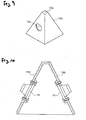
- FIG.6 is an external appearance view showing of an external appearance of a loudspeaker enclosure 11 according to a second embodiment of the present invention.
- the enclosure 11 has an upper structural body 12 shaped into a frustum of quadrangular pyramid that widens toward a bottom, a lower structural body 13 shaped into a frustum of quadrangular pyramid that narrows toward a bottom, and an internal structural body 14 shaped into a frustum of quadrangular pyramid that widens toward a bottom.
- the internal structural body 14 projects from an interior of the upper structural body 12 to the outer side via an upper surface of the upper structural body 12, and these bodies are joined together in such a manner that center axes of respective frustums of quadrangular pyramid are aligned mutually.
- a lower end outer edge of the upper structural body 12 and an upper end outer edge of the lower structural body 13 are joined together in such a manner that center axes of respective frustums of quadrangular pyramid are aligned mutually.
- FIG.7 is a sectional view of the enclosure 11 shown in FIG.6, and shows a section when the enclosure 11 is cut by a plane containing a center axis of the frustum of quadrangular pyramid and a center point of a base of the quadrangular pyramid.
- the enclosure 11 is formed as a hollow structure.
- the upper structural body 12 has an outer top plate 12a provided to its top end, and an outer wall 12b shaped into a frustum of quadrangular pyramid.
- FIG.8 is an external appearance view showing an external appearance of the upper structural body 12 shown in FIG.7.
- An inner structural body projecting hole 12c is opened in a center portion of the outer top plate 12a.
- a lower end of the lower structural body 13 is opened, and the lower structural body 13 has an outer wall 13a shaped into a frustum of quadrangular pyramid that narrows toward a bottom, and a projected wall 13b extending obliquely upward from a lower end of the outer wall 13a.
- the projected wall 13b is formed in a position that cannot be seen from the direction shown in FIG.6.
- the internal structural body 14 has an inner top plate 14a provided to its top end, and an inner wall 14b shaped into a frustum of quadrangular pyramid that widens toward an opened bottom.
- FIG.9 is an external appearance view showing an external appearance of the inner structural body 14 shown in FIG.7.
- a loudspeaker installing hole 14c are provided in a center portion of the above inner wall 14b.
- another loudspeaker installing hole 14c is provided in the opposing inner wall 14b that cannot be seen from the direction shown in FIG.9. Accordingly, two loudspeakers are provided to the inner structural body 14 (see FIG.7).
- a loudspeaker 18 is fitted into the loudspeaker installing hole 14c from the inner surface side of the inner wall 14b.
- the inner structural body 14 projects to the outside from an inner side of the upper structural body 12 through the inner structural body projecting hole 12c that is opened in the outer top plate 12a.
- the outer top plate 12a and the inner wall 14b are joined tightly on a periphery of the inner structural body projecting hole 12c.
- a duct 16 (second sound wave guiding portion) is formed by inner peripheral surfaces of the upper structural body 12 and the lower structural body 13 and an outer peripheral surface of a not-projected portion of the inner structural body 14.
- the duct 16 constitutes an opening portion 17 between the lower end portion of the inner wall 14b and the top end portion of the projected wall 13b.
- FIG.11 is a view showing a state that the loudspeaker 18 is driven in the above configuration.
- a sound wave 19a emitted from a front face of a diaphragm of the loudspeaker 18 is passed through a space surrounded with the internal structural body 14 (first sound wave guiding portion), and is emitted outward through an opening portion formed at the bottom of the lower structural body 13.
- a sound wave 19b emitted from a rear face of the diaphragm of the loudspeaker 18 propagates through the duct 16 and arrives at the opening portion 17. Then, the sound wave 19b emitted from a rear face of the diaphragm is emitted in the direction to suppress a spread of the sound wave that is emitted through the opening portion of the internal structural body 14. In this case, since the sound wave 19b emitted from the rear face of the diaphragm is opposite in phase to the sound wave 19a emitted from the front face of the diaphragm, the sound waves interfere mutually around the opening portion 17 to lower a sound pressure there.
- the sound wave 9a emitted from the front face of the diaphragm of the loudspeaker 8 is emitted into a space surrounded with the internal structural body 4, while the sound wave 9b emitted from the rear face of the diaphragm of the loudspeaker 8 is emitted into the duct 6.
- the sound wave 9a emitted from the front face of the diaphragm of the loudspeaker 8 may be emitted into the duct 6, while the sound wave 9b emitted from the rear face of the diaphragm of the loudspeaker 8 may be emitted into the space surrounded with the internal structural body 4.
- the loudspeaker 8 may be fitted in the opposite direction to that in the first embodiment.
- both two loudspeakers 18 may be fitted in the opposite direction mutually, as in the second embodiment.
- only one loudspeaker 18 may be fitted in the opposite direction.
- respective loudspeakers 18 may be driven in an opposite phase mutually.
- the lower end of the lower structural body 3 is opened, and the lower structural body 3 has the outer wall 3a shaped into the frustum of circular cone that narrows toward the bottom, and the projected wall 3b extending obliquely upward from the lower end of the outer wall 3a.
- the lower structural body 3 may be constructed to have the outer wall 3a shaped into the frustum of circular cone that narrows toward the bottom, a lower wall 3c extending in the horizontal direction from the lower end of the outer wall 3a, and the projected wall 3b extending obliquely upward from the end portion of the lower wall 3c.
- a bending of the duct 6 is made gentle by adding the lower wall 3c as another wall between the outer wall 3a and the projected wall 3b in the first embodiment, so that a sound wave propagating through the duct 6 is be guided smoothly to the opening portion 7.
- an angle between adjacent walls at a boundary portion may be increased by constructing the lower wall 3c by means of plural sheets of walls.
- respective walls may be constructed by a curved surface to eliminate an angle at the boundary portion, and also a curvature of the duct 6 can be made smooth when respective walls are constructed by a curved surface.
- a converging type acoustic lens 50 may be arranged to the front face of the loudspeaker 8 on the sound wave emission side in the first embodiment. With this arrangement, the directivity of the sound wave emitted from the loudspeaker can be increased much more in the width direction of the acoustic lens 50.
- the enclosure of the present invention can be used as a luminaire by installing a light source to the enclosure 1. Also, when a light source is installed into the inside of the enclosure 1, this enclosure can be used as a pendant type luminaire. Thus, the user can listen a sound from the loudspeaker 8 in an illuminated area and its vicinity.
- an annulus light source 30 is installed in the duct 6.
- the light source 30 is secured to the outer wall 2b by a supporting body 31.
- a part or all of the inner wall 4b should be formed of a light transmitting material.
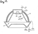
- FIG.16 is an external appearance view showing an external appearance of a loudspeaker enclosure 21 according to a variation 5 of the present invention.
- the enclosure 21 has a cylindrical upper structural body 22, an internal structural body 24 shaped into a frustum of circular cone that widens toward a bottom, a lower structural body 23 shaped into a frustum of circular cone that narrows toward a bottom, and a tube 10.
- a lower end outer edge of the upper structural body 22 and an upper end outer edge of the internal structural body 24 or a lower end outer edge of the internal structural body 24 and an upper end inner edge of the lower structural body 23 are joined together such that center axes of respective structural bodies are aligned mutually.
- FIG. 17 is a sectional view of the enclosure 21 shown in FIG.16, and shows a section when the enclosure is cut by a plane containing respective center axes.
- the upper structural body 22 has an outer top plate 22a provided to its top end, and a cylindrical outer wall 22b. Here, holes that are connected to the tubes 10 are opened in the outer wall 22b.
- a lower end of the lower structural body 23 is opened, and the lower structural body 23 has an outer wall 23a shaped into a frustum of circular cone that narrows toward a bottom, a projected wall 23b extending obliquely upward from a lower end of the outer wall 23a, and an upper wall 23d extending from a top end of the outer wall 23a in the horizontal direction.
- holes that are connected to the tubes 10 are opened in the upper wall 23d.
- This projected wall 23b is formed in a position that cannot be seen from the direction shown in FIG.16.
- the internal structural body 24 has an inner top plate 24a provided to its top end, and an inner wall 24b shaped into a frustum of circular cone that widens toward an opened bottom.
- a loudspeaker 28 is fitted to the inner top plate 24a.
- the upper structural body 22 and the lower structural body 23 are connected via the tubes 10. Also, an opening portion 27 is formed between the lower end portion of the inner wall 24b and the top end portion of the projected wall 23b.
- the sound wave emitted from the rear face of the diaphragm of the loudspeaker 28 propagates through the tubes 10, and is emitted from the opening portion 27. Therefore, the similar advantages to those of the first embodiment can be achieved, and a reduction in size and weight can be attained further more.
Landscapes
- Health & Medical Sciences (AREA)
- Otolaryngology (AREA)
- Physics & Mathematics (AREA)
- Engineering & Computer Science (AREA)
- Acoustics & Sound (AREA)
- Signal Processing (AREA)
- Obtaining Desirable Characteristics In Audible-Bandwidth Transducers (AREA)
- Details Of Audible-Bandwidth Transducers (AREA)
Abstract
Description
- The present invention relates to a loudspeaker enclosure and a loudspeaker system capable of improving a directivity of a loudspeaker.
- As the loudspeaker system capable of enhancing the directivity, i.e., the loudspeaker system having the so-called narrow directivity, there is the loudspeaker array, for example. The loudspeaker array enhances the directivity by controlling respective amplitudes and phases in individual loudspeakers. The system using the loudspeaker array tends to increase in size because a plurality of loudspeakers are used, however, for example, in
JP-A-2006-101464 - The loudspeaker with the hood can enhance the directivity even in the small-sized loudspeaker, nevertheless such loudspeaker has the problem the directivity is deteriorated because a sound diffracts at an edge portion of an opening portion of the hood. In
JP-A-2006-101464 - The present invention has been made in view of the above circumstances, and it is an object of the present invention to provide a loudspeaker enclosure and a loudspeaker system capable of reducing a size and improving a directivity.
- In order to solve the above problems, the present invention provides a loudspeaker enclosure, comprising:
- a first sound wave guiding portion that partitions a first space which is separated by one face of a diaphragm of a loudspeaker and has a first opening portion; and
- a second sound wave guiding portion that partitions a second space which is separated by the other face of the diaphragm of the loudspeaker and has a second opening portion,
- Also, the present invention provides a loudspeaker system, comprising:
- a loudspeaker;
- a first sound wave guiding portion that partitions a first space which is separated by one face of a diaphragm of a loudspeaker and has a first opening portion; and
- a second sound wave guiding portion that partitions a second space which is separated by the other face of the diaphragm of the loudspeaker and has a second opening portion,
- Preferably, the first space is separated by one faces of diaphragms of a plurality of loudspeakers. The second space is separated by the other faces of the diaphragms of the loudspeakers.
- Preferably, at least one of the first sound wave guiding portion and the second sound wave guiding portion has a light source.
Here, it is preferable that, at least one of the first sound wave guiding portion and the second sound wave guiding portion is formed of light transmitting material. - Preferably, the loudspeaker has an acoustic lens.
- Preferably, the first sound wave emitted from the first opening portion through the first sound wave guiding portion is opposite in phase to the second sound wave emitted from the second opening portion through the second sound wave guiding portion.
- According to the present invention, a diffraction sound generated at an edge portion of an opening portion when a sound wave is emitted from the opening portion of the enclosure can be reduced. Therefore, the loudspeaker enclosure can be reduced small in size and can improve the directivity.
- The above objects and advantages of the present invention will become more apparent by describing in detail preferred exemplary embodiments thereof with reference to the accompanying drawings, wherein:
- FIG.1 is an external appearance view of an enclosure according to a first embodiment of the present invention;
- FIG.2 is a sectional view of the enclosure according to the first embodiment of the present invention;
- FIG.3 is an external appearance view of an internal structural body of the enclosure according to the first embodiment of the present invention;
- FIG.4 is a sectional view of a neighborhood of a loudspeaker that is installed in the enclosure according to the first embodiment of the present invention;
- FIG.5 is a conceptual view of actions of a sound wave in an interior of the enclosure according to the first embodiment of the present invention;
- FIG.6 is an external appearance view of an enclosure according to a second embodiment of the present invention;
- FIG.7 is a sectional view of the enclosure according to the second embodiment of the present invention;
- FIG.8 is an external appearance view of an upper structural body of the enclosure according to the second embodiment of the present invention;
- FIG.9 is an external appearance view of an inner structural body of the enclosure according to the second embodiment of the present invention;
- FIG.10 is a sectional view of a neighborhood of a loudspeaker that is installed in the enclosure according to the second embodiment of the present invention;
- FIG. 11 is a conceptual view of actions of a sound wave in an interior of the enclosure according to the second embodiment of the present invention;
- FIG.12 is a sectional view of a neighborhood of a loudspeaker that is installed in an enclosure according to a
variation 1 of the present invention; - FIG.13 is a sectional view of an enclosure according to the
variation 1 of the present invention; - FIG. 14 is a sectional view of an enclosure according to a
variation 2 of the present invention; - FIG.15 is a sectional view of an enclosure according to a
variation 4 of the present invention; - FIG.16 is an external appearance view of an enclosure according to a
variation 5 of the present invention; and - FIG.17 is a sectional view of the enclosure according to the
variation 5 of the present invention. - Embodiments of the present invention will be explained hereinafter.
- FIG.1 is an external appearance view showing an external appearance of a
loudspeaker enclosure 1 as a first embodiment of the present invention. Theenclosure 1 has an upperstructural body 2 shaped into a frustum of circular cone that widens toward a bottom, and a lowerstructural body 3 shaped into a frustum of circular cone that narrows toward a bottom. A lower end outer edge of the upperstructural body 2 and an upper end outer edge of the lowerstructural body 3 are joined together such that center axes of respective circular cones are aligned mutually. - FIG.2 is a sectional view of the
enclosure 1 shown in FIG. 1 and shows a section when theenclosure 1 is cut by a plane containing the center axis of the frustum of circular cone. As shown in FIG.2, theenclosure 1 is formed as a hollow structure. Also, the upperstructural body 2 has anouter top plate 2a provided to its top end, and anouter wall 2b formed as a frustum of circular cone. - A lower end of the lower
structural body 3 is opened, and the lowerstructural body 3 has aouter wall 3a shaped into a frustum of circular cone that narrows toward a bottom, and a projectedwall 3b extending obliquely upward from a lower end of theouter wall 3a. Here, the projectedwall 3b is formed in a position that cannot be seen from the direction shown in FIG.1. - An internal
structural body 4 shaped into a frustum of circular cone that widens toward a bottom to have a shape similar to the upperstructural body 2 is provided in the inside of theenclosure 1. The internalstructural body 4 has aninner top plate 4a provided to its top end, and aninner wall 4b shaped into a frustum of circular cone that widens toward an opened bottom. - FIG.3 is an external appearance view of an external appearance of the internal
structural body 4 shown in FIG.2. Aloudspeaker installing hole 4c is opened in a center portion of theinner top plate 4a. The internalstructural body 4 is supported by rod-like struts top plate 2a. - As shown in FIG.4, a
loudspeaker 8 is fitted into theloudspeaker installing hole 4c from the lower surface side of the innertop plate 4a. - A duct 6 (second sound wave guiding portion) is constructed by inner peripheral surfaces of the upper
structural body 2 and the lowerstructural body 3 and an outer peripheral surface of the internalstructural body 4. Theduct 6 constitutes anopening portion 7 between a lower end portion of theinner wall 4b and an upper end portion of the projectedwall 3b. - FIG.5 is a view showing a state that the
loudspeaker 8 is driven in the above structure. When theloudspeaker 8 is driven, asound wave 9a emitted from a front face of a diaphragm (normally a cone paper) of theloudspeaker 8 is passed through a space surrounded with the internal structural body 4 (first sound wave guiding portion), and is emitted outward through an opening portion formed at the bottom of the lowerstructural body 3. - In contrast, a
sound wave 9b emitted from a rear face of the diaphragm of theloudspeaker 8 propagates through theduct 6 and arrives at theopening portion 7. Then, thesound wave 9b emitted from a rear face of the diaphragm is emitted in the direction to suppress a spread of the sound wave that is emitted through the opening portion of the internalstructural body 4. In this case, since thesound wave 9b emitted from the rear face of the diaphragm is opposite in phase to thesound wave 9a emitted from the front face of the diaphragm, the sound waves interfere mutually around theopening portion 7 to lower a sound pressure there. As a result, an amount of diffraction of the sound at the opening portion of theenclosure 1 is reduced, and the directivity of the sound toward the bottom side of a frustum of circular cone of theenclosure 1 along a center axis can be improved. - FIG.6 is an external appearance view showing of an external appearance of a
loudspeaker enclosure 11 according to a second embodiment of the present invention. Theenclosure 11 has an upperstructural body 12 shaped into a frustum of quadrangular pyramid that widens toward a bottom, a lowerstructural body 13 shaped into a frustum of quadrangular pyramid that narrows toward a bottom, and an internalstructural body 14 shaped into a frustum of quadrangular pyramid that widens toward a bottom. The internalstructural body 14 projects from an interior of the upperstructural body 12 to the outer side via an upper surface of the upperstructural body 12, and these bodies are joined together in such a manner that center axes of respective frustums of quadrangular pyramid are aligned mutually. Also, a lower end outer edge of the upperstructural body 12 and an upper end outer edge of the lowerstructural body 13 are joined together in such a manner that center axes of respective frustums of quadrangular pyramid are aligned mutually. - FIG.7 is a sectional view of the
enclosure 11 shown in FIG.6, and shows a section when theenclosure 11 is cut by a plane containing a center axis of the frustum of quadrangular pyramid and a center point of a base of the quadrangular pyramid. As shown in FIG.7, theenclosure 11 is formed as a hollow structure. Also, the upperstructural body 12 has an outertop plate 12a provided to its top end, and anouter wall 12b shaped into a frustum of quadrangular pyramid. - FIG.8 is an external appearance view showing an external appearance of the upper
structural body 12 shown in FIG.7. An inner structuralbody projecting hole 12c is opened in a center portion of the outertop plate 12a. - A lower end of the lower
structural body 13 is opened, and the lowerstructural body 13 has anouter wall 13a shaped into a frustum of quadrangular pyramid that narrows toward a bottom, and a projectedwall 13b extending obliquely upward from a lower end of theouter wall 13a. Here, the projectedwall 13b is formed in a position that cannot be seen from the direction shown in FIG.6. - The internal
structural body 14 has an innertop plate 14a provided to its top end, and aninner wall 14b shaped into a frustum of quadrangular pyramid that widens toward an opened bottom. - FIG.9 is an external appearance view showing an external appearance of the inner
structural body 14 shown in FIG.7. A loudspeaker installing hole 14c are provided in a center portion of the aboveinner wall 14b. Also, another loudspeaker installing hole 14c is provided in the opposinginner wall 14b that cannot be seen from the direction shown in FIG.9. Accordingly, two loudspeakers are provided to the inner structural body 14 (see FIG.7). - As shown in FIG.10, a
loudspeaker 18 is fitted into the loudspeaker installing hole 14c from the inner surface side of theinner wall 14b. - The inner
structural body 14 projects to the outside from an inner side of the upperstructural body 12 through the inner structuralbody projecting hole 12c that is opened in the outertop plate 12a. The outertop plate 12a and theinner wall 14b are joined tightly on a periphery of the inner structuralbody projecting hole 12c. - A duct 16 (second sound wave guiding portion) is formed by inner peripheral surfaces of the upper
structural body 12 and the lowerstructural body 13 and an outer peripheral surface of a not-projected portion of the innerstructural body 14. Theduct 16 constitutes an openingportion 17 between the lower end portion of theinner wall 14b and the top end portion of the projectedwall 13b. - FIG.11 is a view showing a state that the
loudspeaker 18 is driven in the above configuration. When theloudspeaker 18 is driven, asound wave 19a emitted from a front face of a diaphragm of theloudspeaker 18 is passed through a space surrounded with the internal structural body 14 (first sound wave guiding portion), and is emitted outward through an opening portion formed at the bottom of the lowerstructural body 13. - In contrast, a
sound wave 19b emitted from a rear face of the diaphragm of theloudspeaker 18 propagates through theduct 16 and arrives at the openingportion 17. Then, thesound wave 19b emitted from a rear face of the diaphragm is emitted in the direction to suppress a spread of the sound wave that is emitted through the opening portion of the internalstructural body 14. In this case, since thesound wave 19b emitted from the rear face of the diaphragm is opposite in phase to thesound wave 19a emitted from the front face of the diaphragm, the sound waves interfere mutually around the openingportion 17 to lower a sound pressure there. As a result, an amount of diffraction of the sound at the opening portion of theenclosure 11 is reduced, and the directivity of the sound toward the bottom side of a frustum of quadrangular pyramid of theenclosure 11 along a center axis can be improved. - With the above, embodiments of the present invention are explained. But the present invention can be carried out in various modes given as follows.
- In the first embodiment, the
sound wave 9a emitted from the front face of the diaphragm of theloudspeaker 8 is emitted into a space surrounded with the internalstructural body 4, while thesound wave 9b emitted from the rear face of the diaphragm of theloudspeaker 8 is emitted into theduct 6. In avariation 1, thesound wave 9a emitted from the front face of the diaphragm of theloudspeaker 8 may be emitted into theduct 6, while thesound wave 9b emitted from the rear face of the diaphragm of theloudspeaker 8 may be emitted into the space surrounded with the internalstructural body 4. In such case, as shown in FIG.12, theloudspeaker 8 may be fitted in the opposite direction to that in the first embodiment. - Similarly, both two
loudspeakers 18 may be fitted in the opposite direction mutually, as in the second embodiment. Alternately, as shown in FIG.13, only oneloudspeaker 18 may be fitted in the opposite direction. When only oneloudspeaker 18 is fitted in the opposite direction,respective loudspeakers 18 may be driven in an opposite phase mutually. - In the first embodiment, the lower end of the lower
structural body 3 is opened, and the lowerstructural body 3 has theouter wall 3a shaped into the frustum of circular cone that narrows toward the bottom, and the projectedwall 3b extending obliquely upward from the lower end of theouter wall 3a. In avariation 2, as shown in FIG.14, the lowerstructural body 3 may be constructed to have theouter wall 3a shaped into the frustum of circular cone that narrows toward the bottom, alower wall 3c extending in the horizontal direction from the lower end of theouter wall 3a, and the projectedwall 3b extending obliquely upward from the end portion of thelower wall 3c. That is, a bending of theduct 6 is made gentle by adding thelower wall 3c as another wall between theouter wall 3a and the projectedwall 3b in the first embodiment, so that a sound wave propagating through theduct 6 is be guided smoothly to theopening portion 7. In addition, in order to render the bending of theduct 6 gentle, an angle between adjacent walls at a boundary portion may be increased by constructing thelower wall 3c by means of plural sheets of walls. Also, respective walls may be constructed by a curved surface to eliminate an angle at the boundary portion, and also a curvature of theduct 6 can be made smooth when respective walls are constructed by a curved surface. - As indicated by a broken line in FIG.4, a converging type
acoustic lens 50 may be arranged to the front face of theloudspeaker 8 on the sound wave emission side in the first embodiment. With this arrangement, the directivity of the sound wave emitted from the loudspeaker can be increased much more in the width direction of theacoustic lens 50. - In the first embodiment, the enclosure of the present invention can be used as a luminaire by installing a light source to the
enclosure 1. Also, when a light source is installed into the inside of theenclosure 1, this enclosure can be used as a pendant type luminaire. Thus, the user can listen a sound from theloudspeaker 8 in an illuminated area and its vicinity. - As a situation that a light source is installed in the inside of the
enclosure 1, for example, as shown in FIG.15, an annulus light source 30 is installed in theduct 6. The light source 30 is secured to theouter wall 2b by a supportingbody 31. In this case, a part or all of theinner wall 4b should be formed of a light transmitting material. - FIG.16 is an external appearance view showing an external appearance of a
loudspeaker enclosure 21 according to avariation 5 of the present invention. Theenclosure 21 has a cylindrical upperstructural body 22, an internalstructural body 24 shaped into a frustum of circular cone that widens toward a bottom, a lowerstructural body 23 shaped into a frustum of circular cone that narrows toward a bottom, and atube 10. A lower end outer edge of the upperstructural body 22 and an upper end outer edge of the internalstructural body 24 or a lower end outer edge of the internalstructural body 24 and an upper end inner edge of the lowerstructural body 23 are joined together such that center axes of respective structural bodies are aligned mutually. - FIG. 17 is a sectional view of the
enclosure 21 shown in FIG.16, and shows a section when the enclosure is cut by a plane containing respective center axes. The upperstructural body 22 has an outertop plate 22a provided to its top end, and a cylindricalouter wall 22b. Here, holes that are connected to thetubes 10 are opened in theouter wall 22b. - A lower end of the lower
structural body 23 is opened, and the lowerstructural body 23 has anouter wall 23a shaped into a frustum of circular cone that narrows toward a bottom, a projectedwall 23b extending obliquely upward from a lower end of theouter wall 23a, and anupper wall 23d extending from a top end of theouter wall 23a in the horizontal direction. Here, holes that are connected to thetubes 10 are opened in theupper wall 23d. This projectedwall 23b is formed in a position that cannot be seen from the direction shown in FIG.16. - The internal
structural body 24 has an innertop plate 24a provided to its top end, and an inner wall 24b shaped into a frustum of circular cone that widens toward an opened bottom. Aloudspeaker 28 is fitted to the innertop plate 24a. - The upper
structural body 22 and the lowerstructural body 23 are connected via thetubes 10. Also, an openingportion 27 is formed between the lower end portion of the inner wall 24b and the top end portion of the projectedwall 23b. - In operation of the above configuration, the sound wave emitted from the rear face of the diaphragm of the
loudspeaker 28 propagates through thetubes 10, and is emitted from the openingportion 27. Therefore, the similar advantages to those of the first embodiment can be achieved, and a reduction in size and weight can be attained further more. - In this case, the variations though explained by using the first embodiment can also be applied to the second embodiment and other variations.
- Although the invention has been illustrated and described for the particular preferred embodiments, it is apparent to a person skilled in the art that various changes and modifications can be made on the basis of the teachings of the invention. It is apparent that such changes and modifications are within the spirit, scope, and intention of the invention as defined by the appended claims.
wherein a position of the second opening portion of the second sound wave guiding portion is set so that a second sound wave emitted from the second opening portion of the second sound wave guiding portion is emitted in a direction to suppress a spread of a first sound wave emitted from the first opening portion of the first sound wave guiding portion.
wherein a position of the second opening portion of the second sound wave guiding portion is set so that a second sound wave emitted from the second opening portion of the second sound wave guiding portion is emitted in a direction to suppress a spread of a first sound wave emitted from the first opening portion of the first sound wave guiding portion.
Claims (11)
- A loudspeaker enclosure, comprising:a first sound wave guiding portion that partitions a first space which is separated by one face of a diaphragm of a loudspeaker and has a first opening portion; anda second sound wave guiding portion that partitions a second space which is separated by the other face of the diaphragm of the loudspeaker and has a second opening portion,wherein the second opening portion of the second sound wave guiding portion is provided around the first opening portion of the first sound wave guiding portion; and
wherein a position of the second opening portion of the second sound wave guiding portion is set so that a second sound wave emitted from the second opening portion of the second sound wave guiding portion is emitted in a direction to suppress a spread of a first sound wave emitted from the first opening portion of the first sound wave guiding portion. - The loudspeaker enclosure according to claim 1, wherein the first space is separated by one faces of diaphragms of a plurality of loudspeakers; and
wherein the second space is separated by the other faces of the diaphragms of the loudspeakers. - The loudspeaker enclosure according to claim 1 or 2, wherein at least one of the first sound wave guiding portion and the second sound wave guiding portion has a light source.
- The loudspeaker enclosure according to claim 3, wherein at least one of the first sound wave guiding portion and the second sound wave guiding portion is formed of light transmitting material.
- The loudspeaker enclosure according to one of the preceding claims,
wherein the first sound wave emitted from the first opening portion through the first sound wave guiding portion is opposite in phase to the second sound wave emitted from the second opening portion through the second sound wave guiding portion. - A loudspeaker system, comprising:a loudspeaker;a first sound wave guiding portion that partitions a first space which is separated by one face of a diaphragm of a loudspeaker and has a first opening portion; anda second sound wave guiding portion that partitions a second space which is separated by the other face of the diaphragm of the loudspeaker and has a second opening portion,wherein the second opening portion of the second sound wave guiding portion is provided around the first opening portion of the first sound wave guiding portion; and
wherein a position of the second opening portion of the second sound wave guiding portion is set so that a second sound wave emitted from the second opening portion of the second sound wave guiding portion is emitted in a direction to suppress a spread of a first sound wave emitted from the first opening portion of the first sound wave guiding portion. - The loudspeaker system according to claim 6, wherein the first space is separated by one faces of diaphragms of a plurality of loudspeakers; and
wherein the second space is separated by the other faces of the diaphragms of the loudspeakers. - The loudspeaker system according to claim 6 or 7, wherein at least one of the first sound wave guiding portion and the second sound wave guiding portion has a light source.
- The loudspeaker system according to claim 8, wherein at least one of the first sound wave guiding portion and the second sound wave guiding portion is formed of light transmitting material.
- The loudspeaker system according to any of claims 6 to 9, wherein the loudspeaker has an acoustic lens.
- The loudspeaker system according to any of claims 6 to 10, wherein the first sound wave emitted from the first opening portion through the first sound wave guiding portion is opposite in phase to the second sound wave emitted from the second opening portion through the second sound wave guiding portion.
Applications Claiming Priority (1)
| Application Number | Priority Date | Filing Date | Title |
|---|---|---|---|
| JP2006182303A JP4229147B2 (en) | 2006-06-30 | 2006-06-30 | Speaker enclosure and speaker system |
Publications (2)
| Publication Number | Publication Date |
|---|---|
| EP1874081A2 true EP1874081A2 (en) | 2008-01-02 |
| EP1874081A3 EP1874081A3 (en) | 2009-10-21 |
Family
ID=38520738
Family Applications (1)
| Application Number | Title | Priority Date | Filing Date |
|---|---|---|---|
| EP07012841A Withdrawn EP1874081A3 (en) | 2006-06-30 | 2007-06-29 | Loudspeaker enclosure and loudspeaker system |
Country Status (4)
| Country | Link |
|---|---|
| US (1) | US20080013768A1 (en) |
| EP (1) | EP1874081A3 (en) |
| JP (1) | JP4229147B2 (en) |
| CN (1) | CN101098568A (en) |
Cited By (1)
| Publication number | Priority date | Publication date | Assignee | Title |
|---|---|---|---|---|
| DE102015120176B4 (en) | 2015-11-20 | 2019-08-14 | Arnautovic Faruk | Sound generation system |
Families Citing this family (9)
| Publication number | Priority date | Publication date | Assignee | Title |
|---|---|---|---|---|
| US8254615B2 (en) * | 2009-10-09 | 2012-08-28 | Ricky David Schultz | Loudspeaker with acoustic speaker lens |
| GR1007393B (en) * | 2010-03-15 | 2011-09-09 | Βλαδιμηρος Σεραφειμ Μανελιδης | Loudspeaker with air feedback |
| CN102098599A (en) * | 2010-12-31 | 2011-06-15 | 国光电器股份有限公司 | Loudspeaker box structure |
| JP2012148657A (en) * | 2011-01-18 | 2012-08-09 | Denso Corp | Vehicle approach notification system |
| CN104811873B (en) * | 2014-12-23 | 2019-02-15 | 北京太和开元科技有限公司 | sound device |
| CN104954931B (en) * | 2015-06-25 | 2018-05-11 | 西南大学 | Orient pronunciation device |
| GB201806194D0 (en) * | 2018-04-16 | 2018-05-30 | Native Design Ltd | Lighting and speaker device and annular LED assembly |
| JP6663974B1 (en) * | 2018-12-26 | 2020-03-13 | 有限会社ゾルゾ | Speaker device |
| US11991497B1 (en) * | 2022-10-28 | 2024-05-21 | xMEMS Labs, Inc. | Acoustic device and holder flattening frequency response |
Family Cites Families (7)
| Publication number | Priority date | Publication date | Assignee | Title |
|---|---|---|---|---|
| US4949386A (en) * | 1988-05-23 | 1990-08-14 | Hill Amel L | Speaker system |
| US5432860A (en) * | 1990-02-09 | 1995-07-11 | Mitsubishi Denki Kabushiki Kaisha | Speaker system |
| US6062339A (en) * | 1995-11-27 | 2000-05-16 | Hathaway; Dana B. | Compact spiral cavity loudspeaker enclosure |
| KR100198290B1 (en) * | 1996-11-27 | 1999-06-15 | 구자홍 | Dome Speaker System Structure |
| US5975236A (en) * | 1998-01-08 | 1999-11-02 | Yamamoto; Shuji | Speaker assembly |
| US6625292B2 (en) * | 2001-11-15 | 2003-09-23 | Jl Audio, Inc. | Ported loudspeaker enclosure |
| JP4843209B2 (en) * | 2003-11-12 | 2011-12-21 | 甫 羽田野 | Speaker device |
-
2006
- 2006-06-30 JP JP2006182303A patent/JP4229147B2/en not_active Expired - Fee Related
-
2007
- 2007-06-28 CN CNA2007101124942A patent/CN101098568A/en active Pending
- 2007-06-29 EP EP07012841A patent/EP1874081A3/en not_active Withdrawn
- 2007-06-29 US US11/770,875 patent/US20080013768A1/en not_active Abandoned
Cited By (1)
| Publication number | Priority date | Publication date | Assignee | Title |
|---|---|---|---|---|
| DE102015120176B4 (en) | 2015-11-20 | 2019-08-14 | Arnautovic Faruk | Sound generation system |
Also Published As
| Publication number | Publication date |
|---|---|
| JP4229147B2 (en) | 2009-02-25 |
| EP1874081A3 (en) | 2009-10-21 |
| US20080013768A1 (en) | 2008-01-17 |
| JP2008011425A (en) | 2008-01-17 |
| CN101098568A (en) | 2008-01-02 |
Similar Documents
| Publication | Publication Date | Title |
|---|---|---|
| US20080013768A1 (en) | Loudspeaker Enclosure and Loudspeaker System | |
| US8385575B2 (en) | Reflex enclosure | |
| US20040251079A1 (en) | Closed loop embedded audio transmission line technology for loudspeaker enclosures and systems | |
| JP2008278145A (en) | Sound wave path length correcting structure for speaker system | |
| EP3653932B1 (en) | Led illumination device with speaker function, and method for extracting light and sound from led illumination device with speaker function | |
| US10129636B2 (en) | Speaker device for improving sound quality in high frequency band | |
| US8479874B2 (en) | Acoustic enclosure for loudspeakers | |
| US20080128199A1 (en) | Acoustic waveguide and electroacoustic system incorporating same | |
| US11172276B2 (en) | Annular radiation speaker structure | |
| JPH05268690A (en) | Loud speaker unit having wide-angle directivity | |
| US6585077B2 (en) | Sound-producing device with acoustic waveguide | |
| JP2020178336A5 (en) | ||
| US2845135A (en) | Auxiliary wave propagating and directing attachment for loudspeaker diaphragms | |
| US6675932B2 (en) | Speaker housing configured to minimize standing waves and resonate above the frequency range of transducers | |
| US8259981B2 (en) | Horn-loaded acoustic line source | |
| CN113966621B (en) | Low profile speakers | |
| JPH0336896A (en) | Built-in type on-vehicle speaker | |
| US20060120548A1 (en) | Speaker device | |
| JP2006101464A (en) | Speaker device | |
| JP2018201175A (en) | speaker | |
| KR100233064B1 (en) | Speaker assembly | |
| JP6286913B2 (en) | Speaker stand | |
| JP5304230B2 (en) | Flat speaker | |
| JPH09327093A (en) | Piezoelectric speaker | |
| JP2012082616A (en) | Partition panel |
Legal Events
| Date | Code | Title | Description |
|---|---|---|---|
| PUAI | Public reference made under article 153(3) epc to a published international application that has entered the european phase |
Free format text: ORIGINAL CODE: 0009012 |
|
| AK | Designated contracting states |
Kind code of ref document: A2 Designated state(s): AT BE BG CH CY CZ DE DK EE ES FI FR GB GR HU IE IS IT LI LT LU LV MC MT NL PL PT RO SE SI SK TR |
|
| AX | Request for extension of the european patent |
Extension state: AL BA HR MK YU |
|
| PUAL | Search report despatched |
Free format text: ORIGINAL CODE: 0009013 |
|
| AK | Designated contracting states |
Kind code of ref document: A3 Designated state(s): AT BE BG CH CY CZ DE DK EE ES FI FR GB GR HU IE IS IT LI LT LU LV MC MT NL PL PT RO SE SI SK TR |
|
| AX | Request for extension of the european patent |
Extension state: AL BA HR MK RS |
|
| AKX | Designation fees paid | ||
| STAA | Information on the status of an ep patent application or granted ep patent |
Free format text: STATUS: THE APPLICATION IS DEEMED TO BE WITHDRAWN |
|
| 18D | Application deemed to be withdrawn |
Effective date: 20100422 |
|
| REG | Reference to a national code |
Ref country code: DE Ref legal event code: 8566 |