EP1873852B1 - Conducting plates for fuel cell elements - Google Patents
Conducting plates for fuel cell elements Download PDFInfo
- Publication number
- EP1873852B1 EP1873852B1 EP06291083A EP06291083A EP1873852B1 EP 1873852 B1 EP1873852 B1 EP 1873852B1 EP 06291083 A EP06291083 A EP 06291083A EP 06291083 A EP06291083 A EP 06291083A EP 1873852 B1 EP1873852 B1 EP 1873852B1
- Authority
- EP
- European Patent Office
- Prior art keywords
- sheet
- fuel cell
- alloy
- cell element
- conducting plate
- Prior art date
- Legal status (The legal status is an assumption and is not a legal conclusion. Google has not performed a legal analysis and makes no representation as to the accuracy of the status listed.)
- Active
Links
Images




Classifications
-
- H—ELECTRICITY
- H01—ELECTRIC ELEMENTS
- H01M—PROCESSES OR MEANS, e.g. BATTERIES, FOR THE DIRECT CONVERSION OF CHEMICAL ENERGY INTO ELECTRICAL ENERGY
- H01M8/00—Fuel cells; Manufacture thereof
- H01M8/02—Details
- H01M8/0202—Collectors; Separators, e.g. bipolar separators; Interconnectors
- H01M8/0204—Non-porous and characterised by the material
- H01M8/0206—Metals or alloys
- H01M8/0208—Alloys
-
- H—ELECTRICITY
- H01—ELECTRIC ELEMENTS
- H01M—PROCESSES OR MEANS, e.g. BATTERIES, FOR THE DIRECT CONVERSION OF CHEMICAL ENERGY INTO ELECTRICAL ENERGY
- H01M8/00—Fuel cells; Manufacture thereof
- H01M8/02—Details
-
- C—CHEMISTRY; METALLURGY
- C22—METALLURGY; FERROUS OR NON-FERROUS ALLOYS; TREATMENT OF ALLOYS OR NON-FERROUS METALS
- C22C—ALLOYS
- C22C19/00—Alloys based on nickel or cobalt
- C22C19/03—Alloys based on nickel or cobalt based on nickel
- C22C19/05—Alloys based on nickel or cobalt based on nickel with chromium
-
- C—CHEMISTRY; METALLURGY
- C22—METALLURGY; FERROUS OR NON-FERROUS ALLOYS; TREATMENT OF ALLOYS OR NON-FERROUS METALS
- C22C—ALLOYS
- C22C27/00—Alloys based on rhenium or a refractory metal not mentioned in groups C22C14/00 or C22C16/00
-
- C—CHEMISTRY; METALLURGY
- C22—METALLURGY; FERROUS OR NON-FERROUS ALLOYS; TREATMENT OF ALLOYS OR NON-FERROUS METALS
- C22C—ALLOYS
- C22C38/00—Ferrous alloys, e.g. steel alloys
- C22C38/04—Ferrous alloys, e.g. steel alloys containing manganese
-
- C—CHEMISTRY; METALLURGY
- C22—METALLURGY; FERROUS OR NON-FERROUS ALLOYS; TREATMENT OF ALLOYS OR NON-FERROUS METALS
- C22C—ALLOYS
- C22C38/00—Ferrous alloys, e.g. steel alloys
- C22C38/06—Ferrous alloys, e.g. steel alloys containing aluminium
-
- C—CHEMISTRY; METALLURGY
- C22—METALLURGY; FERROUS OR NON-FERROUS ALLOYS; TREATMENT OF ALLOYS OR NON-FERROUS METALS
- C22C—ALLOYS
- C22C38/00—Ferrous alloys, e.g. steel alloys
- C22C38/18—Ferrous alloys, e.g. steel alloys containing chromium
- C22C38/40—Ferrous alloys, e.g. steel alloys containing chromium with nickel
- C22C38/44—Ferrous alloys, e.g. steel alloys containing chromium with nickel with molybdenum or tungsten
-
- C—CHEMISTRY; METALLURGY
- C22—METALLURGY; FERROUS OR NON-FERROUS ALLOYS; TREATMENT OF ALLOYS OR NON-FERROUS METALS
- C22C—ALLOYS
- C22C38/00—Ferrous alloys, e.g. steel alloys
- C22C38/18—Ferrous alloys, e.g. steel alloys containing chromium
- C22C38/40—Ferrous alloys, e.g. steel alloys containing chromium with nickel
- C22C38/46—Ferrous alloys, e.g. steel alloys containing chromium with nickel with vanadium
-
- C—CHEMISTRY; METALLURGY
- C22—METALLURGY; FERROUS OR NON-FERROUS ALLOYS; TREATMENT OF ALLOYS OR NON-FERROUS METALS
- C22C—ALLOYS
- C22C38/00—Ferrous alloys, e.g. steel alloys
- C22C38/18—Ferrous alloys, e.g. steel alloys containing chromium
- C22C38/40—Ferrous alloys, e.g. steel alloys containing chromium with nickel
- C22C38/50—Ferrous alloys, e.g. steel alloys containing chromium with nickel with titanium or zirconium
-
- C—CHEMISTRY; METALLURGY
- C22—METALLURGY; FERROUS OR NON-FERROUS ALLOYS; TREATMENT OF ALLOYS OR NON-FERROUS METALS
- C22C—ALLOYS
- C22C38/00—Ferrous alloys, e.g. steel alloys
- C22C38/18—Ferrous alloys, e.g. steel alloys containing chromium
- C22C38/40—Ferrous alloys, e.g. steel alloys containing chromium with nickel
- C22C38/54—Ferrous alloys, e.g. steel alloys containing chromium with nickel with boron
-
- C—CHEMISTRY; METALLURGY
- C22—METALLURGY; FERROUS OR NON-FERROUS ALLOYS; TREATMENT OF ALLOYS OR NON-FERROUS METALS
- C22C—ALLOYS
- C22C38/00—Ferrous alloys, e.g. steel alloys
- C22C38/18—Ferrous alloys, e.g. steel alloys containing chromium
- C22C38/40—Ferrous alloys, e.g. steel alloys containing chromium with nickel
- C22C38/58—Ferrous alloys, e.g. steel alloys containing chromium with nickel with more than 1.5% by weight of manganese
-
- H—ELECTRICITY
- H01—ELECTRIC ELEMENTS
- H01M—PROCESSES OR MEANS, e.g. BATTERIES, FOR THE DIRECT CONVERSION OF CHEMICAL ENERGY INTO ELECTRICAL ENERGY
- H01M4/00—Electrodes
- H01M4/02—Electrodes composed of, or comprising, active material
- H01M4/64—Carriers or collectors
- H01M4/70—Carriers or collectors characterised by shape or form
- H01M4/80—Porous plates, e.g. sintered carriers
-
- H—ELECTRICITY
- H01—ELECTRIC ELEMENTS
- H01M—PROCESSES OR MEANS, e.g. BATTERIES, FOR THE DIRECT CONVERSION OF CHEMICAL ENERGY INTO ELECTRICAL ENERGY
- H01M8/00—Fuel cells; Manufacture thereof
- H01M8/02—Details
- H01M8/0202—Collectors; Separators, e.g. bipolar separators; Interconnectors
- H01M8/0204—Non-porous and characterised by the material
- H01M8/0206—Metals or alloys
- H01M8/0208—Alloys
- H01M8/021—Alloys based on iron
-
- H—ELECTRICITY
- H01—ELECTRIC ELEMENTS
- H01M—PROCESSES OR MEANS, e.g. BATTERIES, FOR THE DIRECT CONVERSION OF CHEMICAL ENERGY INTO ELECTRICAL ENERGY
- H01M8/00—Fuel cells; Manufacture thereof
- H01M8/10—Fuel cells with solid electrolytes
-
- Y—GENERAL TAGGING OF NEW TECHNOLOGICAL DEVELOPMENTS; GENERAL TAGGING OF CROSS-SECTIONAL TECHNOLOGIES SPANNING OVER SEVERAL SECTIONS OF THE IPC; TECHNICAL SUBJECTS COVERED BY FORMER USPC CROSS-REFERENCE ART COLLECTIONS [XRACs] AND DIGESTS
- Y02—TECHNOLOGIES OR APPLICATIONS FOR MITIGATION OR ADAPTATION AGAINST CLIMATE CHANGE
- Y02E—REDUCTION OF GREENHOUSE GAS [GHG] EMISSIONS, RELATED TO ENERGY GENERATION, TRANSMISSION OR DISTRIBUTION
- Y02E60/00—Enabling technologies; Technologies with a potential or indirect contribution to GHG emissions mitigation
- Y02E60/10—Energy storage using batteries
-
- Y—GENERAL TAGGING OF NEW TECHNOLOGICAL DEVELOPMENTS; GENERAL TAGGING OF CROSS-SECTIONAL TECHNOLOGIES SPANNING OVER SEVERAL SECTIONS OF THE IPC; TECHNICAL SUBJECTS COVERED BY FORMER USPC CROSS-REFERENCE ART COLLECTIONS [XRACs] AND DIGESTS
- Y02—TECHNOLOGIES OR APPLICATIONS FOR MITIGATION OR ADAPTATION AGAINST CLIMATE CHANGE
- Y02E—REDUCTION OF GREENHOUSE GAS [GHG] EMISSIONS, RELATED TO ENERGY GENERATION, TRANSMISSION OR DISTRIBUTION
- Y02E60/00—Enabling technologies; Technologies with a potential or indirect contribution to GHG emissions mitigation
- Y02E60/30—Hydrogen technology
- Y02E60/50—Fuel cells
-
- Y—GENERAL TAGGING OF NEW TECHNOLOGICAL DEVELOPMENTS; GENERAL TAGGING OF CROSS-SECTIONAL TECHNOLOGIES SPANNING OVER SEVERAL SECTIONS OF THE IPC; TECHNICAL SUBJECTS COVERED BY FORMER USPC CROSS-REFERENCE ART COLLECTIONS [XRACs] AND DIGESTS
- Y02—TECHNOLOGIES OR APPLICATIONS FOR MITIGATION OR ADAPTATION AGAINST CLIMATE CHANGE
- Y02P—CLIMATE CHANGE MITIGATION TECHNOLOGIES IN THE PRODUCTION OR PROCESSING OF GOODS
- Y02P70/00—Climate change mitigation technologies in the production process for final industrial or consumer products
- Y02P70/50—Manufacturing or production processes characterised by the final manufactured product
-
- Y—GENERAL TAGGING OF NEW TECHNOLOGICAL DEVELOPMENTS; GENERAL TAGGING OF CROSS-SECTIONAL TECHNOLOGIES SPANNING OVER SEVERAL SECTIONS OF THE IPC; TECHNICAL SUBJECTS COVERED BY FORMER USPC CROSS-REFERENCE ART COLLECTIONS [XRACs] AND DIGESTS
- Y10—TECHNICAL SUBJECTS COVERED BY FORMER USPC
- Y10T—TECHNICAL SUBJECTS COVERED BY FORMER US CLASSIFICATION
- Y10T428/00—Stock material or miscellaneous articles
- Y10T428/12—All metal or with adjacent metals
- Y10T428/12993—Surface feature [e.g., rough, mirror]
Definitions
- the present invention relates to conducting plates for fuel cell elements.
- fuel cells constitute a nonpolluting source of electricity. They are current generators of the electrochemical type, the operating principle of which consists in passing a fuel, generally hydrogen, over an anode so as to generate, in the presence of a catalyst (such as platinum), protons which, after they have passed through an electrolyte such as a polymer membrane come into contact with an oxidizer, generally oxygen, which is generated at the cathode, in order to produce water, in combination with electrons which also come from the anode. The water is discharged from the system, as is the heat generated. The circulation of the electrons from the anode to the cathode produces electricity.
- a catalyst such as platinum
- the hydrogen used in fuel cells constitutes an almost inexhaustible planet-wide element. It can be produced by the electrolysis of water by renewable energy means, for example hydroelectric, wind or solar power, or by means of a source of nuclear power. Alternatively, it can be produced by the reforming of natural gas or by the gasification and then thermochemical reforming of biomass.
- Fuel cells may find various applications, in particular in the development of "clean" vehicles, that is to say those not emitting carbon dioxide or other pollutants potentially harmful to the environment or to human health, or in the development of low-power portable systems such as mobile telephones and portable computers.
- a fuel cell comprises a stack of several cell elements, each of which consist of an electrolyte, such as a proton exchange membrane or PEM, sandwiched between the anode and the cathode, the whole assembly constituting an active core or MEA (Membrane/Electrode Assembly) which is itself contained between two conducting plates.
- Current collectors are provided at the ends of the stack of cell elements.
- the conducting plates include channels into which the feed gases flow and from which the water is discharged. They may be of the monopolar or bipolar type.
- monopolar is understood to mean that each cell element comprises an anode plate and a cathode plate in direct contact (or in contact via a separator consisting of a corrugated conducting metal plate) with the respective cathode and anode plates of the adjacent cell elements.
- bipolar is understood to mean that each plate comprises an anode face and a cathode face and, by itself, ensures connection between two adjacent cell elements.
- a coolant is made to circulate in channels formed in the bipolar plate or formed between two adjacent monopolar plates or else in passages provided in the corrugated separator plate.
- a gas diffusion layer or GDL consisting of conducting fibres, is in principle interposed between each electrode and the plate that faces it.
- the conducting plates are conventionally made of graphite or a carbon/polymer composite, or metal plates.
- Graphite makes it possible to achieve good performance because of its high electrical and thermal conductivities and its low contact resistance. It can also easily be machined, offering the possibility of optimizing the geometry of the channels passing through it. Finally, its high corrosion resistance guarantees the longevity of the cell element core. However, machining graphite is a lengthy and expensive operation, whatever the volume of production, its use being reserved for laboratory cell elements and a few prototypes.
- a carbon/polymer composite allows plates to be obtained by moulding, which considerably reduces the costs.
- carbon/polymer composite plates remain too heavy for mass markets, such as the automobile market.
- the performance of this material is inferior to that of graphite, because of a lower conductivity and less favourable channel geometries as a result of the manufacturing constraints.
- Stainless steel in fact constitutes the material the best suited to the mass production of fuel cells, with a cost from 5 to 10 times less than that of carbon/polymer composites. It allows the production of plates offering good electrical and thermal conduction, combined with satisfactory mechanical strength of the cell elements. It also has the advantage of being lightweight, occupying little space and able to be subjected to many proven assembly techniques.
- Application FR-2 860 104 has suggested a fuel cell configuration making it possible to obtain a high surface area for contact between a monopolar plate and the corresponding diffusion layer, and thus to reduce the electronic contact resistance between these two elements with a view to improving both the efficiency and the power of the cell for a given current density.
- the surface of the plate is roughened by sandblasting, filing or abrasion, so as to be suited, or even matched, to that of the diffusion layer. This posttreatment is potentially more expensive than the "native" treatment according to the invention.
- the alloy grade A286 has been described in Application CA-518181 .
- This is a ferrous alloy of the austenitic type containing chromium, nickel and titanium, which is described as having good ductility and high mechanical strength at high temperature, which properties can be exploited for the manufacture of aircraft engines exposed to high stresses, especially thermal stresses.
- This alloy can be subjected to a solution heat treatment at a temperature close to 980°C (1800°F) followed by a tempering operation, and can be age-hardened. More recently, it has been suggested to use A286 grade alloys for various applications in the aeronautical field, the automotive field (turbocomponents, exhaust manifolds), energy field (turbines) and oil industry.
- the subject of the invention is therefore, according to a first embodiment, the use, for the manufacture of a monopolar or bipolar conducting plate for a fuel cell element, of at least one alloy comprising, in percentages by weight:
- the aforementioned alloy corresponds to a stainless steel of A286 grade, defined by reference to the ASTM standard, it is also identified by the reference S66286 according to the UNS standard and 1.4943 according to the WNr standard.
- impurities is understood for the purpose of the present invention to mean elements that are unavoidably present and result from the process for manufacturing the alloy. These are in particular nitrogen, phosphorus, selenium, copper, zirconium, cerium and/or lanthanum.
- a preferred alloy for use in the present invention contains:
- Another subject of the invention is a sheet comprising at least one alloy as defined above, characterized in that it has, at least on one of its faces, an arithmetic mean roughness Sa of 0.12 ⁇ m or higher, a maximum height amplitude St of less than 4 ⁇ m and, preferably, a developed area Sdr of greater than 0.2%.
- sheet is understood within the present invention to mean a rolled product in sheet form, with a substantially flat surface and substantially rectangular cross section.
- the parameters Sa, St and Sdr are 3D surface finish parameters defined with respect to a mean plane obtained by rectification, by the plane of the mean squares of the measured surface, and then by centring the heights about the mean. They may be determined from a recording of the surface topography, which can be obtained in particular by a tactile sensor.
- the construction of the surface topography in 3D is accomplished by measuring a series of N parallel profiles made up of M points, uniformly spaced apart, so as to cover a rectangular surface. A recording of the height z as a function of the position x in the profile, and the position y of the profile in the surface, are obtained.
- the arithmetic mean roughness of the sheet according to the invention is preferably greater than 0.12 ⁇ m and generally less than 0.36 ⁇ m.
- maximum height amplitude St is understood to be the total height of the surface, defined by the difference between the height of the highest peak and the depth of the deepest trough. This parameter is determined by extrapolation with respect to the 2D parameter.
- the maximum height amplitude St of the sheet according to the invention is preferably less than 4 ⁇ m and generally greater than 1.5 ⁇ m.
- a perfectly plane surface will have an Sdr of 0%.
- the developed surface area Sdr of the sheet according to the invention is preferably greater than 0.2% and generally less than 1%.
- the aforementioned surfaced sheet can be manufactured by a process comprising the following steps in succession:
- the subject of the invention is therefore also a process for surfacing a sheet based on the aforementioned alloy, as described above.
- the abovementioned rolling, annealing and pickling steps constitute metallurgical operations well known to those skilled in the art.
- combustion furnaces may be used for carrying out the annealing in an oxidizing atmosphere.
- the cold rolling may be carried out on stainless steel strip having for example a thickness between 2 and 5 mm. It may be from a slab obtained by pouring molten alloy from a tundish, through a nozzle, into a mould having cold surfaces, in which the metal product starts to solidify.
- the walls of the mould may be stationary copper or copper alloy walls, or rolls rotating in opposite directions from each other, or endless belts.
- the strip used in the above process may result from hot-rolling the aforementioned slab.
- the cold-rolled strip may for example have a thickness of 0.05 mm to 1.5 mm.
- the acid used in the pickling step may be especially chosen from sulphuric acid, nitric acid, hydrofluoric acid and the mixtures thereof, preferably tending to have a solution whose pH is equal to 2 or less.
- the acid may be brought into contact with the annealed sheet in particular by spraying or by making the strip run through a container of an acid solution or through a cascade of containers (preferably three containers, such as tanks) containing identical or different acid solutions.
- the surfacing process described above may include other steps than those mentioned above, carried out before or after any one of the aforementioned steps, and especially an additional electrolytic pickling step. In general, it further includes a step of rinsing, preferably with water, and then of drying the pickled sheet.
- the subject of the invention is also the use of the surfaced sheet described above, preferably obtained by the aforementioned process, for the manufacture of a conducting plate (whether of the monopolar or bipolar type) for a fuel cell element.
- the sheets (whether surfaced or not) used according to the invention in the manufacture of conducting plates are advantageously subjected to a particular cold-forming process that makes it possible to obtain the optimum plate geometries for the purpose of the intended use, and in particular the desired channel profiles, without impairing the corrosion resistance and electrical conductivity properties of the plates.
- the subject of the invention is therefore also a process for manufacturing a conducting plate for a fuel cell element, comprising the surfacing by the process described above of a sheet containing an alloy as defined above, said process further including at least the following steps:
- the succession of first and second deformations gives the sheet an elongation of at least 25% to 35% relative to the initial length of the sheet.
- the subject of the invention is also the plate thus obtained.
- This process may be carried out in a hydraulic or mechanical press using at least two tools of different shapes.
- it may be carried out using what is called a "following" tool which applies at least two successive impressions (the following ones being applied on top of the previous ones) for example to sheets measuring 10 x 20 cm.
- the elongation conferred on the sheet in this process is expressed with respect to the initial developed length of the sheet, measured along its central part. This is a mean elongation, in so far as certain regions of the sheet will be deformed more than others.
- This cold-forming process makes it possible to distribute the deformations undergone by the metal in all directions, and over the maximum area of the initial sheet, so as to best use the elongatability of the metal. This results in a profile for the incoming gas channels that is compatible with fuel cell operation (in particular, satisfactory lifetime and compactness). Furthermore, this process makes it possible to conform the sheet to the assembly, sealing and connection means for the gas inlets and outlets that will be subsequently attached to it. It should be noted that this method does not impair the surface conformation of the sheet, that is to say any particular roughness that it has, nor does it impair its low electrical resistance. Finally, this is a simpler and less expensive method than hydroforming.
- a further subject of the invention is a fuel cell element comprising at least one monopolar or bipolar conducting plate comprising at least an alloy as defined above, preferably a surfaced sheet or a conducting plate such as those described above.
- a cell element conventionally comprises, apart from said plate, an anode, a cathode and an electrolyte, advantageously together with at least one diffusion layer.
- the electrodes may conventionally be made of a carbon, platinum or polymer layer having for example a thickness of 10 to 15 ⁇ m.
- a preferred electrolyte consists of a proton exchange polymer membrane which may for example have a thickness of 20 to 50 ⁇ m.
- a diffusion layer of the "woven" type such as the CARBEL CL model sold by W.L. Gore & Associates
- a diffusion layer of the "felt" type such as the 30BC model sold by SGL. In general, this is a porous material containing carbon fibres with a diameter of 5 to 40 ⁇ m.
- Yet another subject of the invention is a fuel cell, in particular of the PEMFC (proton exchange membrane fuel cell) type, containing such a cell element.
- PEMFC proto exchange membrane fuel cell
- the fuel cells according to the invention may be used for supplying electricity to a vehicle, such as a motor vehicle, or a telecommunication means, such as a relay antenna or a mobile telephone.
- a vehicle such as a motor vehicle
- a telecommunication means such as a relay antenna or a mobile telephone.
- Another subject of the present invention is therefore the use of fuel cells as defined above for supplying electricity to a vehicle, such as a motor vehicle, or a telecommunication means, such as a relay antenna or a mobile telephone.
- Figure 1 illustrates a conventional fuel cell element.
- the cell element 1 illustrated contains an electrolyte 2 interposed between an anode 3 and a cathode 4, each being in contact with an anode plate 5 and a cathode plate 6, respectively.
- the cell consists of a stack of cell elements 1, such as that illustrated in Figure 1 , which are joined together between two current collectors, one of which, the current collector 7, is shown in this figure.
- Example 1 Manufacture of a surfaced alloy sheet according to the invention
- a surfaced sheet was manufactured from the alloy SUPERIMPHY ® SY286 from Imphy Alloys, the precise composition of which was:
- a hot-rolled sheet with a thickness of 4 mm was used, which was cold-rolled in several passes with an intermediate annealing treatment between each cold-rolling pass, so as to obtain a strip thickness of around 0.2 mm.
- the strip was annealed according to the invention at 1080°C in an open combustion continuous furnace 27 m in length at a run speed of 20 m/min, the oxygen content in the reducing atmosphere being about 8%.
- the strip obtained was then pickled by passing it through three successive baths:
- the sheet obtained had a thickness of 0.2 mm and an arithmetic mean roughness Sa of 0.23 ⁇ m.
- the calculated St and Sdr values were 2.16 ⁇ m and 0.344%, respectively.
- Example 2 Evaluation of the surface finish as a function of the sheet manufacturing process
- Figure 2 illustrates the surface finish of a sheet manufactured under conditions similar to those of example 1, which appears to consist of a multitude of bumps. Its surface is characterized by an arithmetic mean roughness Sa of 0.186 ⁇ m, a maximum height amplitude St of 2.16 ⁇ m and a developed surface area Sdr of 0.344%.
- Figure 3 illustrates, for comparison, a sheet manufactured from the same SUPERIMPHY ® SY286 alloy by a process that involves an annealing step in a reducing atmosphere, the surface of which has a succession of protuberances. The surface of this sheet is further characterized by an arithmetic mean roughness Sa of 0.106 ⁇ m, a maximum height amplitude St of 1.04 ⁇ m and a developed surface area Sdr of 0.0767%.
- an SY286 alloy sheet surfaced by the process according to the invention has a characteristic rough surface that cannot be obtained by a conventional process of annealing in a reducing atmosphere.
- Example 3 Evaluation of the electrical surface resistance as a function of the nature of the alloy
- FIG 7 shows that, for two different types of gas diffusion layer (GDL), the contact resistance obtained with alloy SY286 is, here again, the lowest.
- GDL gas diffusion layer
- Example 4 Evaluation of the electrical surface resistance as a function of the sheet manufacturing process
- the electrical contact resistance of two SY286 alloy sheets described in Example 2 was compared as a function of the assembly pressure exerted on each of these sheets in order to join them to an identical diffusion layer.
- the surfacing process according to the invention makes it possible to obtain a sheet having a better conductivity than the sheet prepared according to the conventional process of annealing in hydrogen.
- Example 5 Comparison of the performance of cells based on various alloys
- the performance namely the cell voltage as a function of the current density, was compared, its fuel cells differing from one another by the chemical nature of the material making up their conducting plates.
- the experiments were carried out at an air pressure of 1.1 bar, a hydrogen pressure of 1.25 bar and a cell temperature of 60°C.
- the surfaced SY286 alloy plate according to the invention profiled by a process that includes at least two cold-forming steps, makes it possible to obtain a fuel cell having an electrical performance close to that of a cell based on machined graphite (no significant difference) and better than that of a cell based on a carbon/polymer composite.
- Figure 10 shows that the electrical performance of a fuel cell according to the invention, tested under the abovementioned conditions, is better than that of a cell manufactured from plates made of 316L alloy, which is the reference.
- a long-term cycling test was carried out over 500 hours in order to simulate (under the conditions of Example 6 and with a current density of 0.6 A/cm 2 ) one way of stressing a fuel cell according to the invention, representative of its use as a portable generator.
Landscapes
- Chemical & Material Sciences (AREA)
- Engineering & Computer Science (AREA)
- Materials Engineering (AREA)
- Mechanical Engineering (AREA)
- Metallurgy (AREA)
- Organic Chemistry (AREA)
- General Chemical & Material Sciences (AREA)
- Chemical Kinetics & Catalysis (AREA)
- Electrochemistry (AREA)
- Manufacturing & Machinery (AREA)
- Sustainable Development (AREA)
- Sustainable Energy (AREA)
- Life Sciences & Earth Sciences (AREA)
- Fuel Cell (AREA)
- Heat Treatment Of Sheet Steel (AREA)
- Cleaning And De-Greasing Of Metallic Materials By Chemical Methods (AREA)
Abstract
Description
- The present invention relates to conducting plates for fuel cell elements.
- For many years research has been conducted with a view to developing new energy production systems that counter the steady depletion of oil reserves and that at the same time take into account current and future requirements in combating pollution and the associated climate changes.
- In this regard, fuel cells constitute a nonpolluting source of electricity. They are current generators of the electrochemical type, the operating principle of which consists in passing a fuel, generally hydrogen, over an anode so as to generate, in the presence of a catalyst (such as platinum), protons which, after they have passed through an electrolyte such as a polymer membrane come into contact with an oxidizer, generally oxygen, which is generated at the cathode, in order to produce water, in combination with electrons which also come from the anode. The water is discharged from the system, as is the heat generated. The circulation of the electrons from the anode to the cathode produces electricity.
- The hydrogen used in fuel cells constitutes an almost inexhaustible planet-wide element. It can be produced by the electrolysis of water by renewable energy means, for example hydroelectric, wind or solar power, or by means of a source of nuclear power. Alternatively, it can be produced by the reforming of natural gas or by the gasification and then thermochemical reforming of biomass.
- Fuel cells may find various applications, in particular in the development of "clean" vehicles, that is to say those not emitting carbon dioxide or other pollutants potentially harmful to the environment or to human health, or in the development of low-power portable systems such as mobile telephones and portable computers.
- In general, a fuel cell comprises a stack of several cell elements, each of which consist of an electrolyte, such as a proton exchange membrane or PEM, sandwiched between the anode and the cathode, the whole assembly constituting an active core or MEA (Membrane/Electrode Assembly) which is itself contained between two conducting plates. Current collectors are provided at the ends of the stack of cell elements.
- The conducting plates include channels into which the feed gases flow and from which the water is discharged. They may be of the monopolar or bipolar type. The term "monopolar" is understood to mean that each cell element comprises an anode plate and a cathode plate in direct contact (or in contact via a separator consisting of a corrugated conducting metal plate) with the respective cathode and anode plates of the adjacent cell elements. The term "bipolar" is understood to mean that each plate comprises an anode face and a cathode face and, by itself, ensures connection between two adjacent cell elements. In general, a coolant is made to circulate in channels formed in the bipolar plate or formed between two adjacent monopolar plates or else in passages provided in the corrugated separator plate.
- A gas diffusion layer or GDL, consisting of conducting fibres, is in principle interposed between each electrode and the plate that faces it.
- The conducting plates are conventionally made of graphite or a carbon/polymer composite, or metal plates.
- Graphite makes it possible to achieve good performance because of its high electrical and thermal conductivities and its low contact resistance. It can also easily be machined, offering the possibility of optimizing the geometry of the channels passing through it. Finally, its high corrosion resistance guarantees the longevity of the cell element core. However, machining graphite is a lengthy and expensive operation, whatever the volume of production, its use being reserved for laboratory cell elements and a few prototypes.
- A carbon/polymer composite allows plates to be obtained by moulding, which considerably reduces the costs. However, although 10 to 20 times less expensive than graphite plates of the same dimensions, carbon/polymer composite plates remain too heavy for mass markets, such as the automobile market. Moreover, the performance of this material is inferior to that of graphite, because of a lower conductivity and less favourable channel geometries as a result of the manufacturing constraints.
- Stainless steel in fact constitutes the material the best suited to the mass production of fuel cells, with a cost from 5 to 10 times less than that of carbon/polymer composites. It allows the production of plates offering good electrical and thermal conduction, combined with satisfactory mechanical strength of the cell elements. It also has the advantage of being lightweight, occupying little space and able to be subjected to many proven assembly techniques.
- However, stainless steel has certain drawbacks that remain to be overcome, namely:
- the electrical surface resistance of this material, inherent due to the presence of an oxide layer (or passive film) on the surface of the metal, reduces the performance of the cell elements as a result of ohmic losses occurring at the interface between the conducting plate and the gas diffusion layer;
- corrosion of the metals, in particular chromium, in the acid reducing medium of the fuel cell releases cations which, by contaminating the cell membranes, limit their lifetime; and
- limited optimization of the plate geometry because of difficulty in forming the material.
- It has already been suggested in Application
US 2002/0172849 to use nickel-chromium austenitic alloys to manufacture bipolar plates having high conductivity and good corrosion resistance. These alloys contain at least 50% by weight of chromium and nickel, the nickel being preferably predominant. The best properties of these alloys, compared with 316 stainless steel conventionally recommended for this use, are attributed to their high nickel content. - Moreover, a comparison of the performance of bipolar plates having various chemical compositions has been presented in the publication by D.P. Davies et al., "Stainless steel as a bipolar plate material for solid polymer fuel cells", Journal of Power Sources 86 (2000) 237-242. Among the 316, 310 and 904L stainless steel plates tested, containing 18 to 25% chromium and 12 to 25% nickel, that made of 904L stainless steel proved to deliver a power density close to that of graphite plates and markedly superior to that of 316 stainless steel. This better performance of 904L steel is attributed to the higher proportion of nickel and chromium that it contains, its performance being assumed to result from a thinner oxide film, which therefore has a lower resistivity.
- Furthermore, Application
FR-2 860 104 - However, there remains the need to have stainless steel conducting plates that allow the manufacture of fuel cell elements having a performance and a lifetime that are comparable to those of cell elements comprising machined graphite plates, whilst still being less expensive.
- Now, the Applicants have discovered that the use of one particular alloy grade, called A286 according to the ASTM standard, allows this requirement to be met. A process for manufacturing conducting plates, likewise allowing this requirement to be met, has also been developed.
- The alloy grade A286 has been described in Application
CA-518181 . This is a ferrous alloy of the austenitic type containing chromium, nickel and titanium, which is described as having good ductility and high mechanical strength at high temperature, which properties can be exploited for the manufacture of aircraft engines exposed to high stresses, especially thermal stresses. This alloy can be subjected to a solution heat treatment at a temperature close to 980°C (1800°F) followed by a tempering operation, and can be age-hardened. More recently, it has been suggested to use A286 grade alloys for various applications in the aeronautical field, the automotive field (turbocomponents, exhaust manifolds), energy field (turbines) and oil industry. - However, to the knowledge of the Applicant it has never been suggested to use this alloy grade for the manufacture of fuel cells. It is apparent to the Applicants that this material has a low electrical surface resistance combined with good corrosion resistance and a cost economically compatible with the envisaged use.
- The subject of the invention is therefore, according to a first embodiment, the use, for the manufacture of a monopolar or bipolar conducting plate for a fuel cell element, of at least one alloy comprising, in percentages by weight:
- 24.0 to 27.0% nickel;
- 13.5 to 16.0% chromium;
- 1.90 to 2.35% titanium;
- 1.0 to 1.5% molybdenum;
- 0.10 to 0.50% vanadium;
- at most 0.08% carbon;
- at most 2.0% manganese;
- at most 1.0% silicon;
- at most 0.35% aluminium;
- at most 0.03% sulphur; and
- at most 0.01% boron,
- The aforementioned alloy corresponds to a stainless steel of A286 grade, defined by reference to the ASTM standard, it is also identified by the reference S66286 according to the UNS standard and 1.4943 according to the WNr standard.
- The term "impurities" is understood for the purpose of the present invention to mean elements that are unavoidably present and result from the process for manufacturing the alloy. These are in particular nitrogen, phosphorus, selenium, copper, zirconium, cerium and/or lanthanum.
- A preferred alloy for use in the present invention contains:
- 24.0 to 25.5% nickel;
- 14.0 to 16.0% chromium;
- 2.00 to 2.30% titanium;
- 1.2 to 1.5% molybdenum;
- 0.10 to 0.50% vanadium;
- at most 0.06% carbon;
- at most 2.0% manganese;
- at most 0.3% silicon;
- at most 0.25% aluminium;
- at most 0.01% sulphur; and
- at most 0.01% boron,
- Another subject of the invention, according to a second embodiment, is a sheet comprising at least one alloy as defined above, characterized in that it has, at least on one of its faces, an arithmetic mean roughness Sa of 0.12 µm or higher, a maximum height amplitude St of less than 4 µm and, preferably, a developed area Sdr of greater than 0.2%.
- The term "sheet" is understood within the present invention to mean a rolled product in sheet form, with a substantially flat surface and substantially rectangular cross section.
- The sheet having these characteristics will be defined, later on in this description, by "surfaced sheet".
- The parameters Sa, St and Sdr are 3D surface finish parameters defined with respect to a mean plane obtained by rectification, by the plane of the mean squares of the measured surface, and then by centring the heights about the mean. They may be determined from a recording of the surface topography, which can be obtained in particular by a tactile sensor. The construction of the surface topography in 3D is accomplished by measuring a series of N parallel profiles made up of M points, uniformly spaced apart, so as to cover a rectangular surface. A recording of the height z as a function of the position x in the profile, and the position y of the profile in the surface, are obtained.
- The expression "arithmetic mean roughness Sa" is understood to be the arithmetic mean of the deviations from the mean:

- The arithmetic mean roughness of the sheet according to the invention is preferably greater than 0.12 µm and generally less than 0.36 µm.
- The expression "maximum height amplitude St" is understood to be the total height of the surface, defined by the difference between the height of the highest peak and the depth of the deepest trough. This parameter is determined by extrapolation with respect to the 2D parameter. The maximum height amplitude St of the sheet according to the invention is preferably less than 4 µm and generally greater than 1.5 µm.
- The expression "developed surface area Sdr" is understood to be the ratio of the increment in the interfacial region of a surface with respect to the test region:

in which M is the number of points per profile, N is the number of profiles and Ai,j represents the interfacial region, defined by:
- A perfectly plane surface will have an Sdr of 0%. The developed surface area Sdr of the sheet according to the invention is preferably greater than 0.2% and generally less than 1%.
- Advantageously, the aforementioned surfaced sheet can be manufactured by a process comprising the following steps in succession:
- (a) a semi-finished product chosen from a thin slab or a hot-rolled sheet is cold rolled;
- (b) the sheet obtained in step (a) is continuously annealed, at a temperature between 900 and 1200°C for a time ranging from 10 seconds to 30 minutes, in an oxidizing atmosphere; and
- (c) the annealed sheet obtained from step (b) is pickled by bringing it into contact with at least one mineral acid at a temperature of between 40 and 100°C.
- The subject of the invention is therefore also a process for surfacing a sheet based on the aforementioned alloy, as described above.
- It has been demonstrated that this process results, surprisingly, in a surface topography and also the formation of a novel passive layer, which are different from those obtained by other standard finishing means, such as bright annealing in a reducing atmosphere (H2 or H2/N2), and are favourable to obtaining a low surface resistance of the material, desirable in the envisaged application.
- The abovementioned rolling, annealing and pickling steps constitute metallurgical operations well known to those skilled in the art. For example, combustion furnaces may be used for carrying out the annealing in an oxidizing atmosphere. In particular, it is preferable to maintain an oxygen content close to 8%.
- The cold rolling may be carried out on stainless steel strip having for example a thickness between 2 and 5 mm. It may be from a slab obtained by pouring molten alloy from a tundish, through a nozzle, into a mould having cold surfaces, in which the metal product starts to solidify. The walls of the mould may be stationary copper or copper alloy walls, or rolls rotating in opposite directions from each other, or endless belts. As a variant, the strip used in the above process may result from hot-rolling the aforementioned slab. The cold-rolled strip may for example have a thickness of 0.05 mm to 1.5 mm.
- The acid used in the pickling step may be especially chosen from sulphuric acid, nitric acid, hydrofluoric acid and the mixtures thereof, preferably tending to have a solution whose pH is equal to 2 or less. The acid may be brought into contact with the annealed sheet in particular by spraying or by making the strip run through a container of an acid solution or through a cascade of containers (preferably three containers, such as tanks) containing identical or different acid solutions.
- The surfacing process described above may include other steps than those mentioned above, carried out before or after any one of the aforementioned steps, and especially an additional electrolytic pickling step. In general, it further includes a step of rinsing, preferably with water, and then of drying the pickled sheet.
- The subject of the invention is also the use of the surfaced sheet described above, preferably obtained by the aforementioned process, for the manufacture of a conducting plate (whether of the monopolar or bipolar type) for a fuel cell element.
- The sheets (whether surfaced or not) used according to the invention in the manufacture of conducting plates are advantageously subjected to a particular cold-forming process that makes it possible to obtain the optimum plate geometries for the purpose of the intended use, and in particular the desired channel profiles, without impairing the corrosion resistance and electrical conductivity properties of the plates.
- The subject of the invention is therefore also a process for manufacturing a conducting plate for a fuel cell element, comprising the surfacing by the process described above of a sheet containing an alloy as defined above, said process further including at least the following steps:
- said sheet having a thickness of 0.05 to 0.5 mm, in particular 0.1 to 0.2 mm, undergoes a first deformation by means of a first tool in order to obtain a corrugated blank; and
- said corrugated blank undergoes a second, tangential deformation by means of a second tool.
- Preferably, the succession of first and second deformations gives the sheet an elongation of at least 25% to 35% relative to the initial length of the sheet.
- The subject of the invention is also the plate thus obtained.
- This process may be carried out in a hydraulic or mechanical press using at least two tools of different shapes. As a variant, it may be carried out using what is called a "following" tool which applies at least two successive impressions (the following ones being applied on top of the previous ones) for example to sheets measuring 10 x 20 cm.
- The elongation conferred on the sheet in this process is expressed with respect to the initial developed length of the sheet, measured along its central part. This is a mean elongation, in so far as certain regions of the sheet will be deformed more than others.
- This cold-forming process makes it possible to distribute the deformations undergone by the metal in all directions, and over the maximum area of the initial sheet, so as to best use the elongatability of the metal. This results in a profile for the incoming gas channels that is compatible with fuel cell operation (in particular, satisfactory lifetime and compactness). Furthermore, this process makes it possible to conform the sheet to the assembly, sealing and connection means for the gas inlets and outlets that will be subsequently attached to it. It should be noted that this method does not impair the surface conformation of the sheet, that is to say any particular roughness that it has, nor does it impair its low electrical resistance. Finally, this is a simpler and less expensive method than hydroforming.
- A further subject of the invention is a fuel cell element comprising at least one monopolar or bipolar conducting plate comprising at least an alloy as defined above, preferably a surfaced sheet or a conducting plate such as those described above. Such a cell element conventionally comprises, apart from said plate, an anode, a cathode and an electrolyte, advantageously together with at least one diffusion layer. The electrodes may conventionally be made of a carbon, platinum or polymer layer having for example a thickness of 10 to 15 µm. A preferred electrolyte consists of a proton exchange polymer membrane which may for example have a thickness of 20 to 50 µm. In particular, it is possible to use a diffusion layer of the "woven" type, such as the CARBEL CL model sold by W.L. Gore & Associates, or a diffusion layer of the "felt" type, such as the 30BC model sold by SGL. In general, this is a porous material containing carbon fibres with a diameter of 5 to 40 µm.
- Yet another subject of the invention is a fuel cell, in particular of the PEMFC (proton exchange membrane fuel cell) type, containing such a cell element.
- The fuel cells according to the invention may be used for supplying electricity to a vehicle, such as a motor vehicle, or a telecommunication means, such as a relay antenna or a mobile telephone.
- Another subject of the present invention is therefore the use of fuel cells as defined above for supplying electricity to a vehicle, such as a motor vehicle, or a telecommunication means, such as a relay antenna or a mobile telephone.
- The invention will now be described with reference to the appended
Figures 1 to 14 , in which: -
Figure 1 illustrates the operating principle of a fuel cell; -
Figure 2 is a latticed representation of the surface of a stainless steel sheet manufactured by the process according to the invention; -
Figure 3 is a latticed representation of a stainless steel sheet manufactured by a process that involves annealing in a reducing atmosphere; -
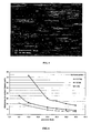
Figure 4 illustrates the surface topography, displayed by scanning electron microscopy, of a stainless steel sheet manufactured by the process according to the invention; -
Figure 5 illustrates the surface topology, displayed by scanning electron microscopy, of a stainless steel sheet manufactured by a process that involves annealing in a reducing atmosphere; -
Figures 6 and7 are curves illustrating the contact resistance of conducting plates made of stainless steel having various chemical compositions, as a function of the pressure exerted on the plate/GDL contact region; -
Figure 8 is a curve illustrating the contact resistance of stainless steel sheets obtained by various processes, as a function of the pressure exerted on the plate/GDL contact region; -
Figure 9 illustrates the polarization curves for fuel cell elements comprising various types of conducting plate; -
Figure 10 illustrates the polarization curves for fuel cell elements comprising plates made of stainless steel of different chemical compositions; and -
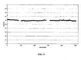
Figure 11 illustrates a "portable generator"-type cycling durability test of a fuel cell element according to the invention. -
Figure 1 illustrates a conventional fuel cell element. Thecell element 1 illustrated contains anelectrolyte 2 interposed between an anode 3 and a cathode 4, each being in contact with an anode plate 5 and a cathode plate 6, respectively. The cell consists of a stack ofcell elements 1, such as that illustrated inFigure 1 , which are joined together between two current collectors, one of which, the current collector 7, is shown in this figure. - The invention will be more clearly understood on reading the following examples, which are given by way of indication but imply no limitation.
- A surfaced sheet was manufactured from the alloy SUPERIMPHY® SY286 from Imphy Alloys, the precise composition of which was:
- 24.43% nickel
- 14.79% chromium
- 2.14% titanium
- 1.46% molybdenum
- 0.306% vanadium
- 0.037 % carbon
- 1.71% manganese
- 0.085% silicon
- 0.168% aluminium
- at most 0.0005% sulphur
- 0.015% phosphorus.
- To do this, a hot-rolled sheet with a thickness of 4 mm was used, which was cold-rolled in several passes with an intermediate annealing treatment between each cold-rolling pass, so as to obtain a strip thickness of around 0.2 mm. After the last rolling pass, the strip was annealed according to the invention at 1080°C in an open combustion continuous furnace 27 m in length at a run speed of 20 m/min, the oxygen content in the reducing atmosphere being about 8%. The strip obtained was then pickled by passing it through three successive baths:
- Bath 1: electrolytic pickling by direct polarization in a 150g/l sodium sulphate bath at a temperature of 75°C,
- Bath 2: electrolytic pickling in a 70 g/l nitric acid bath at a temperature of 40°C; and
- Bath 3: mixture of 100 g/l nitric acid and 20 g/l hydrofluoric acid, at a temperature of 50°C.
- The sheet obtained had a thickness of 0.2 mm and an arithmetic mean roughness Sa of 0.23 µm. The calculated St and Sdr values were 2.16 µm and 0.344%, respectively.
-
Figure 2 illustrates the surface finish of a sheet manufactured under conditions similar to those of example 1, which appears to consist of a multitude of bumps. Its surface is characterized by an arithmetic mean roughness Sa of 0.186 µm, a maximum height amplitude St of 2.16 µm and a developed surface area Sdr of 0.344%.Figure 3 illustrates, for comparison, a sheet manufactured from the same SUPERIMPHY® SY286 alloy by a process that involves an annealing step in a reducing atmosphere, the surface of which has a succession of protuberances. The surface of this sheet is further characterized by an arithmetic mean roughness Sa of 0.106 µm, a maximum height amplitude St of 1.04 µm and a developed surface area Sdr of 0.0767%. - Furthermore, as is apparent from
Figures 4 and5 , the surface topographies displayed by scanning electron microscopy, of the sheet according to the invention and the sheet annealed in a reducing atmosphere (H2) respectively, are very different. - It therefore appears that an SY286 alloy sheet surfaced by the process according to the invention has a characteristic rough surface that cannot be obtained by a conventional process of annealing in a reducing atmosphere.
- The electrical contact resistance of three surfaced alloy sheets, having received the same surface treatment, consisting of the alloy grades F17TNb, A286 (alloy SY286) and 316L respectively, were compared as a function of the assembly pressure exerted on each of these sheets in order to join them to an identical diffusion layer.
- The results illustrated in
Figure 6 show that the A286 alloy sheet used according to the invention offers the lowest contact resistance and therefore the best conducting capability. - A similar measurement was carried out using non-surfaced sheets of SY286 alloy and 904L alloy, which contain similar quantities of nickel.
-
Figure 7 shows that, for two different types of gas diffusion layer (GDL), the contact resistance obtained with alloy SY286 is, here again, the lowest. - From these experiments it is clear that the alloy used according to the invention is a better candidate than the alloys of the prior art for manufacturing conducting plates for fuel cells.
- The electrical contact resistance of two SY286 alloy sheets described in Example 2 was compared as a function of the assembly pressure exerted on each of these sheets in order to join them to an identical diffusion layer. As shown in
Figure 8 , the surfacing process according to the invention makes it possible to obtain a sheet having a better conductivity than the sheet prepared according to the conventional process of annealing in hydrogen. - The performance, namely the cell voltage as a function of the current density, was compared, its fuel cells differing from one another by the chemical nature of the material making up their conducting plates. The experiments were carried out at an air pressure of 1.1 bar, a hydrogen pressure of 1.25 bar and a cell temperature of 60°C.
- As is apparent from
Figure 9 , the surfaced SY286 alloy plate according to the invention, profiled by a process that includes at least two cold-forming steps, makes it possible to obtain a fuel cell having an electrical performance close to that of a cell based on machined graphite (no significant difference) and better than that of a cell based on a carbon/polymer composite. - Furthermore,
Figure 10 shows that the electrical performance of a fuel cell according to the invention, tested under the abovementioned conditions, is better than that of a cell manufactured from plates made of 316L alloy, which is the reference. - A long-term cycling test was carried out over 500 hours in order to simulate (under the conditions of Example 6 and with a current density of 0.6 A/cm2) one way of stressing a fuel cell according to the invention, representative of its use as a portable generator.
- The result of this test, illustrated in
Figure 11 , shows the chemical stability of the conducting plate according to the invention with respect to oxidation in the fuel cell medium. The reductions in performance per unit time are identical, within the precision of the measurement, to those observed in the case of graphite plates or carbon/polymer composite plates.
Claims (17)
- Use, for the manufacture of a monopolar or bipolar conducting plate for a fuel cell element, of at least one alloy comprising, in percentages by weight:24.0 to 27.0% nickel;13.5 to 16.0% chromium;1.90 to 2.35% titanium;1.0 to 1.5% molybdenum;0.10 to 0.50% vanadium;at most 0.08% carbon;at most 2.0% manganese;at most 1.0% silicon;at most 0.35% aluminium;at most 0.03% sulphur; andat most 0.01% boron,the balance consisting of iron and impurities.
- Use according to Claim 1, characterized in that the alloy contains:24.0 to 25.5% nickel;14.0 to 16.0% chromium;2.00 to 2.30% titanium;1.2 to 1.5% molybdenum;0.10 to 0.50% vanadium;at most 0.06% carbon;at most 2.0% manganese;at most 0.3% silicon;at most 0.25% aluminium;at most 0.01% sulphur; andat most 0.01% boron,the balance consisting of iron and impurities.
- Sheet comprising at least one alloy as defined in Claim 1 or 2, characterized in that it has, at least on one of its faces, an arithmetic mean roughness Sa of 0.12 µm or higher, a maximum height amplitude St of less than 4 µm and, preferably, a developed surface area Sdr of greater than 0.2%.
- Process for surfacing a sheet based on an alloy as defined in Claim 1 or 2, comprising the following steps in succession:(a) a semi-finished product chosen from a thin slab or a hot-rolled sheet is cold rolled;(b) the sheet obtained in step (a) is continuously annealed, at a temperature between 900 and 1200°C for a time ranging from 10 seconds to 30 minutes, in an oxidizing atmosphere; and(c) the annealed sheet obtained from step (b) is pickled by bringing it into contact with at least one mineral acid at a temperature of between 40 and 100°C.
- Process according to Claim 4, characterized in that it further includes an electrolytic pickling step.
- Process according to Claim 4 or 5, characterized in that it further includes a step of rinsing, preferably with water, and then of drying the pickled sheet.
- Sheet, characterized in that it can be manufactured by the process according to any one of Claims 4 to 6.
- Use of the sheet according to Claim 7 for the manufacture of a conducting plate for a fuel cell element.
- Process for manufacturing a conducting plate for a fuel cell element, which comprises the surfacing of a sheet containing an alloy as defined in Claim 1 or 2, according to the process defined in Claims 4 to 6, characterized in that it further includes at least the following steps:- said sheet having a thickness of 0.05 to 0.5 mm, in particular 0.1 to 0.2 mm, undergoes a first deformation by means of a first tool in order to obtain a corrugated blank; and- said corrugated blank undergoes a second, tangential deformation by means of a second tool.
- Process according to Claim 9, characterized in that the succession of first and second deformations gives the sheet an elongation of at least 25% to 35% relative to the initial length of the sheet.
- Process according to Claim 9 or 10, characterized in that the sheet is as defined in Claim 3 or 7.
- Conducting plate for a fuel cell element, characterized in that it can be obtained by the process according to any one of Claims 9 to 11.
- Fuel cell element comprising at least one monopolar or bipolar conducting plate comprising at least one alloy as defined in Claim 1 or 2.
- Fuel cell element comprising at least one monopolar or bipolar conducting plate comprising a sheet according to either of Claims 3 and 7.
- Fuel cell element comprising at least one monopolar or bipolar conducting plate according to Claim 12.
- Fuel cell, in particular of the PEMFC (photon exchange membrane fuel cell) type, containing the cell element according to any one of Claims 13 to 15.
- Use of a fuel cell according to Claim 16 for supplying electricity to a vehicle, such as a motor vehicle, or a telecommunication means, such as a relay antenna or a mobile telephone.
Priority Applications (12)
| Application Number | Priority Date | Filing Date | Title |
|---|---|---|---|
| ES06291083T ES2362346T3 (en) | 2006-06-30 | 2006-06-30 | DRIVING PLATES FOR FUEL CELL ELEMENTS. |
| DK06291083.1T DK1873852T3 (en) | 2006-06-30 | 2006-06-30 | Conductive plates for fuel cell elements |
| EP06291083A EP1873852B1 (en) | 2006-06-30 | 2006-06-30 | Conducting plates for fuel cell elements |
| DE602006020424T DE602006020424D1 (en) | 2006-06-30 | 2006-06-30 | Printed circuit boards for fuel cell components |
| AT06291083T ATE500628T1 (en) | 2006-06-30 | 2006-06-30 | CIRCUIT BOARDS FOR FUEL CELL COMPONENTS |
| CA2656517A CA2656517C (en) | 2006-06-30 | 2007-06-19 | Conducting plates for fuel cell elements |
| KR1020097002105A KR101460809B1 (en) | 2006-06-30 | 2007-06-19 | Conducting Plates for Fuel Cell Elements |
| PCT/EP2007/056088 WO2008000662A2 (en) | 2006-06-30 | 2007-06-19 | Conducting plates for fuel cell elements |
| US12/307,002 US20100196799A1 (en) | 2006-06-30 | 2007-06-19 | Conducting plates for fuel cell elements |
| CN2007800247534A CN101485021B (en) | 2006-06-30 | 2007-06-19 | Conductive plates for fuel cell components |
| JP2009517116A JP5363316B2 (en) | 2006-06-30 | 2007-06-19 | Conductive plate for fuel cell element |
| US13/866,274 US9368807B2 (en) | 2006-06-30 | 2013-04-19 | Conducting plates for fuel cell elements |
Applications Claiming Priority (1)
| Application Number | Priority Date | Filing Date | Title |
|---|---|---|---|
| EP06291083A EP1873852B1 (en) | 2006-06-30 | 2006-06-30 | Conducting plates for fuel cell elements |
Publications (2)
| Publication Number | Publication Date |
|---|---|
| EP1873852A1 EP1873852A1 (en) | 2008-01-02 |
| EP1873852B1 true EP1873852B1 (en) | 2011-03-02 |
Family
ID=37451010
Family Applications (1)
| Application Number | Title | Priority Date | Filing Date |
|---|---|---|---|
| EP06291083A Active EP1873852B1 (en) | 2006-06-30 | 2006-06-30 | Conducting plates for fuel cell elements |
Country Status (11)
| Country | Link |
|---|---|
| US (2) | US20100196799A1 (en) |
| EP (1) | EP1873852B1 (en) |
| JP (1) | JP5363316B2 (en) |
| KR (1) | KR101460809B1 (en) |
| CN (1) | CN101485021B (en) |
| AT (1) | ATE500628T1 (en) |
| CA (1) | CA2656517C (en) |
| DE (1) | DE602006020424D1 (en) |
| DK (1) | DK1873852T3 (en) |
| ES (1) | ES2362346T3 (en) |
| WO (1) | WO2008000662A2 (en) |
Families Citing this family (4)
| Publication number | Priority date | Publication date | Assignee | Title |
|---|---|---|---|---|
| JP6260886B2 (en) * | 2012-04-13 | 2018-01-17 | パナソニックIpマネジメント株式会社 | Method for producing separator with gasket for fuel cell, and separator with gasket for fuel cell |
| DE102017130489A1 (en) * | 2017-01-31 | 2018-08-02 | Schaeffler Technologies AG & Co. KG | Bipolar plate for a fuel cell |
| JP7169534B2 (en) * | 2018-07-31 | 2022-11-11 | 大日本印刷株式会社 | Evaporation mask manufacturing method, evaporation mask, and power supply plate for producing evaporation mask |
| CN120015853B (en) * | 2025-02-20 | 2026-04-14 | 北京北冶新材料股份有限公司 | Preparation method of cathode plate of anti-cathode poisoning fuel cell |
Family Cites Families (14)
| Publication number | Priority date | Publication date | Assignee | Title |
|---|---|---|---|---|
| JPH04157090A (en) * | 1990-10-15 | 1992-05-29 | Mitsubishi Heavy Ind Ltd | Welding material |
| JP3242736B2 (en) * | 1993-03-10 | 2001-12-25 | 三菱電機株式会社 | Electrochemical device |
| ATE195559T1 (en) * | 1994-05-21 | 2000-09-15 | Park Yong S | DUPLEX STAINLESS STEEL WITH GOOD CORROSION RESISTANCE |
| WO1996000306A1 (en) * | 1994-06-24 | 1996-01-04 | Nippon Steel Corporation | Method of manufacturing non-oriented electromagnetic steel plate having high magnetic flux density and low iron loss |
| DE4423664A1 (en) * | 1994-07-07 | 1996-05-15 | Bwg Bergwerk Walzwerk | Process for producing cold-rolled steel strips from stainless steel and metal strips, in particular from titanium alloys |
| FR2727982A1 (en) * | 1994-12-13 | 1996-06-14 | Imphy Sa | AUSTENITIC STAINLESS STEEL FOR HOT EMPLOYMENT |
| JPH1092446A (en) * | 1996-09-13 | 1998-04-10 | Fuji Electric Corp Res & Dev Ltd | Solid oxide fuel cell |
| US6300001B1 (en) * | 1997-01-22 | 2001-10-09 | Siemens Aktiengesellschaft | Fuel cell and use of iron-based alloys for the construction of fuel cells |
| JPH10219486A (en) * | 1997-02-05 | 1998-08-18 | Yunikaru:Kk | Pickling liquid and pickling method |
| JPH10321245A (en) * | 1997-03-17 | 1998-12-04 | Toshiba Corp | Molten carbonate fuel cell |
| JP4180753B2 (en) * | 1998-11-10 | 2008-11-12 | 日立金属株式会社 | Fe-base heat-resistant alloy with excellent cold workability and high-temperature heat stability |
| JP3520034B2 (en) * | 2000-07-25 | 2004-04-19 | 古河電気工業株式会社 | Copper alloy materials for electronic and electrical equipment parts |
| JP4816839B2 (en) * | 2000-10-16 | 2011-11-16 | トヨタ自動車株式会社 | Method for producing separator for polymer electrolyte fuel cell |
| CN1721128A (en) * | 2004-07-14 | 2006-01-18 | 天津市天材科技发展有限公司 | Cold working process for high Cr ferrite stainless steel seamless pipe |
-
2006
- 2006-06-30 EP EP06291083A patent/EP1873852B1/en active Active
- 2006-06-30 AT AT06291083T patent/ATE500628T1/en active
- 2006-06-30 DE DE602006020424T patent/DE602006020424D1/en active Active
- 2006-06-30 DK DK06291083.1T patent/DK1873852T3/en active
- 2006-06-30 ES ES06291083T patent/ES2362346T3/en active Active
-
2007
- 2007-06-19 JP JP2009517116A patent/JP5363316B2/en active Active
- 2007-06-19 KR KR1020097002105A patent/KR101460809B1/en active Active
- 2007-06-19 CA CA2656517A patent/CA2656517C/en active Active
- 2007-06-19 US US12/307,002 patent/US20100196799A1/en not_active Abandoned
- 2007-06-19 WO PCT/EP2007/056088 patent/WO2008000662A2/en not_active Ceased
- 2007-06-19 CN CN2007800247534A patent/CN101485021B/en active Active
-
2013
- 2013-04-19 US US13/866,274 patent/US9368807B2/en active Active
Also Published As
| Publication number | Publication date |
|---|---|
| DK1873852T3 (en) | 2011-06-27 |
| ATE500628T1 (en) | 2011-03-15 |
| KR101460809B1 (en) | 2014-12-02 |
| US9368807B2 (en) | 2016-06-14 |
| CA2656517A1 (en) | 2008-01-03 |
| US20100196799A1 (en) | 2010-08-05 |
| CN101485021A (en) | 2009-07-15 |
| KR20090025383A (en) | 2009-03-10 |
| JP2009541962A (en) | 2009-11-26 |
| WO2008000662A3 (en) | 2008-05-02 |
| EP1873852A1 (en) | 2008-01-02 |
| JP5363316B2 (en) | 2013-12-11 |
| US20130330656A1 (en) | 2013-12-12 |
| ES2362346T3 (en) | 2011-07-01 |
| WO2008000662A2 (en) | 2008-01-03 |
| CA2656517C (en) | 2014-06-03 |
| CN101485021B (en) | 2012-01-18 |
| DE602006020424D1 (en) | 2011-04-14 |
Similar Documents
| Publication | Publication Date | Title |
|---|---|---|
| EP1726674B1 (en) | Metal material for current-carrying member, separator for fuel cell utilizing the same and fuel cell including the same | |
| KR100488922B1 (en) | Stainless steel separator for fuel cells, method for making the same, and solid polymer fuel cell including the same | |
| EP2770567B1 (en) | Stainless steel for fuel-cell separators | |
| JP5972877B2 (en) | Method for producing stainless steel for fuel cell separator | |
| KR20130121930A (en) | Method for producing stainless steel for fuel cell separators, stainless steel for fuel cell separators, fuel cell separator, and fuel cell | |
| WO2013018320A1 (en) | Stainless steel for fuel cell separator | |
| US9368807B2 (en) | Conducting plates for fuel cell elements | |
| JP2005123160A (en) | Fuel cell separator, fuel cell stack, fuel cell separator manufacturing method, and fuel cell vehicle | |
| US12286721B2 (en) | Method for chromium upgrading of ferritic steel interconnects for solid oxide cell stack applications | |
| US20060263666A1 (en) | Ferritic stainless steel for use as separators of polymer electrolyte fuel cells and polymer electrolyte fuel cells | |
| JP2004002960A (en) | Austenitic stainless steel for fuel cell separator and method for producing the same | |
| JP2005100813A (en) | FUEL CELL SEPARATOR AND METHOD FOR MANUFACTURING THE SAME, FUEL CELL STACK, AND FUEL CELL VEHICLE | |
| CN100424920C (en) | Fuel cell separator, fuel cell stack, manufacturing method of fuel cell separator, and fuel cell vehicle | |
| US20260045521A1 (en) | Metal separator and manufacturing method therefor | |
| Steels | The Effect of Surface Treatment on the High Temperature Oxidation of Ferritic |
Legal Events
| Date | Code | Title | Description |
|---|---|---|---|
| PUAI | Public reference made under article 153(3) epc to a published international application that has entered the european phase |
Free format text: ORIGINAL CODE: 0009012 |
|
| AK | Designated contracting states |
Kind code of ref document: A1 Designated state(s): AT BE BG CH CY CZ DE DK EE ES FI FR GB GR HU IE IS IT LI LT LU LV MC NL PL PT RO SE SI SK TR |
|
| AX | Request for extension of the european patent |
Extension state: AL BA HR MK YU |
|
| 17P | Request for examination filed |
Effective date: 20080109 |
|
| 17Q | First examination report despatched |
Effective date: 20080502 |
|
| RAP1 | Party data changed (applicant data changed or rights of an application transferred) |
Owner name: L'AIR LIQUIDE, SOCIETE ANONYME POUR L'ETUDE ET L'E Owner name: ALFA LAVAL CORPORATE AB Owner name: ARCELORMITTAL - STAINLESS & NICKEL ALLOYS |
|
| AKX | Designation fees paid |
Designated state(s): AT BE BG CH CY CZ DE DK EE ES FI FR GB GR HU IE IS IT LI LT LU LV MC NL PL PT RO SE SI SK TR |
|
| AXX | Extension fees paid |
Extension state: RS Payment date: 20080109 Extension state: MK Payment date: 20080109 Extension state: HR Payment date: 20080109 Extension state: BA Payment date: 20080109 Extension state: AL Payment date: 20080109 |
|
| GRAP | Despatch of communication of intention to grant a patent |
Free format text: ORIGINAL CODE: EPIDOSNIGR1 |
|
| GRAS | Grant fee paid |
Free format text: ORIGINAL CODE: EPIDOSNIGR3 |
|
| GRAA | (expected) grant |
Free format text: ORIGINAL CODE: 0009210 |
|
| AK | Designated contracting states |
Kind code of ref document: B1 Designated state(s): AT BE BG CH CY CZ DE DK EE ES FI FR GB GR HU IE IS IT LI LT LU LV MC NL PL PT RO SE SI SK TR |
|
| AX | Request for extension of the european patent |
Extension state: AL BA HR MK RS |
|
| REG | Reference to a national code |
Ref country code: GB Ref legal event code: FG4D |
|
| REG | Reference to a national code |
Ref country code: CH Ref legal event code: EP |
|
| REG | Reference to a national code |
Ref country code: IE Ref legal event code: FG4D |
|
| REF | Corresponds to: |
Ref document number: 602006020424 Country of ref document: DE Date of ref document: 20110414 Kind code of ref document: P |
|
| REG | Reference to a national code |
Ref country code: DE Ref legal event code: R096 Ref document number: 602006020424 Country of ref document: DE Effective date: 20110414 |
|
| REG | Reference to a national code |
Ref country code: CH Ref legal event code: NV Representative=s name: KELLER & PARTNER PATENTANWAELTE AG |
|
| REG | Reference to a national code |
Ref country code: NL Ref legal event code: T3 |
|
| REG | Reference to a national code |
Ref country code: SE Ref legal event code: TRGR |
|
| REG | Reference to a national code |
Ref country code: DK Ref legal event code: T3 |
|
| REG | Reference to a national code |
Ref country code: ES Ref legal event code: FG2A Ref document number: 2362346 Country of ref document: ES Kind code of ref document: T3 Effective date: 20110701 |
|
| PG25 | Lapsed in a contracting state [announced via postgrant information from national office to epo] |
Ref country code: LV Free format text: LAPSE BECAUSE OF FAILURE TO SUBMIT A TRANSLATION OF THE DESCRIPTION OR TO PAY THE FEE WITHIN THE PRESCRIBED TIME-LIMIT Effective date: 20110302 Ref country code: LT Free format text: LAPSE BECAUSE OF FAILURE TO SUBMIT A TRANSLATION OF THE DESCRIPTION OR TO PAY THE FEE WITHIN THE PRESCRIBED TIME-LIMIT Effective date: 20110302 |
|
| LTIE | Lt: invalidation of european patent or patent extension |
Effective date: 20110302 |
|
| REG | Reference to a national code |
Ref country code: GR Ref legal event code: EP Ref document number: 20110401272 Country of ref document: GR Effective date: 20110714 |
|
| PG25 | Lapsed in a contracting state [announced via postgrant information from national office to epo] |
Ref country code: FI Free format text: LAPSE BECAUSE OF FAILURE TO SUBMIT A TRANSLATION OF THE DESCRIPTION OR TO PAY THE FEE WITHIN THE PRESCRIBED TIME-LIMIT Effective date: 20110302 Ref country code: SI Free format text: LAPSE BECAUSE OF FAILURE TO SUBMIT A TRANSLATION OF THE DESCRIPTION OR TO PAY THE FEE WITHIN THE PRESCRIBED TIME-LIMIT Effective date: 20110302 Ref country code: BG Free format text: LAPSE BECAUSE OF FAILURE TO SUBMIT A TRANSLATION OF THE DESCRIPTION OR TO PAY THE FEE WITHIN THE PRESCRIBED TIME-LIMIT Effective date: 20110602 Ref country code: CY Free format text: LAPSE BECAUSE OF FAILURE TO SUBMIT A TRANSLATION OF THE DESCRIPTION OR TO PAY THE FEE WITHIN THE PRESCRIBED TIME-LIMIT Effective date: 20110302 |
|
| PG25 | Lapsed in a contracting state [announced via postgrant information from national office to epo] |
Ref country code: PT Free format text: LAPSE BECAUSE OF FAILURE TO SUBMIT A TRANSLATION OF THE DESCRIPTION OR TO PAY THE FEE WITHIN THE PRESCRIBED TIME-LIMIT Effective date: 20110704 Ref country code: EE Free format text: LAPSE BECAUSE OF FAILURE TO SUBMIT A TRANSLATION OF THE DESCRIPTION OR TO PAY THE FEE WITHIN THE PRESCRIBED TIME-LIMIT Effective date: 20110302 |
|
| PG25 | Lapsed in a contracting state [announced via postgrant information from national office to epo] |
Ref country code: RO Free format text: LAPSE BECAUSE OF FAILURE TO SUBMIT A TRANSLATION OF THE DESCRIPTION OR TO PAY THE FEE WITHIN THE PRESCRIBED TIME-LIMIT Effective date: 20110302 Ref country code: IS Free format text: LAPSE BECAUSE OF FAILURE TO SUBMIT A TRANSLATION OF THE DESCRIPTION OR TO PAY THE FEE WITHIN THE PRESCRIBED TIME-LIMIT Effective date: 20110702 Ref country code: CZ Free format text: LAPSE BECAUSE OF FAILURE TO SUBMIT A TRANSLATION OF THE DESCRIPTION OR TO PAY THE FEE WITHIN THE PRESCRIBED TIME-LIMIT Effective date: 20110302 Ref country code: SK Free format text: LAPSE BECAUSE OF FAILURE TO SUBMIT A TRANSLATION OF THE DESCRIPTION OR TO PAY THE FEE WITHIN THE PRESCRIBED TIME-LIMIT Effective date: 20110302 |
|
| PLBE | No opposition filed within time limit |
Free format text: ORIGINAL CODE: 0009261 |
|
| STAA | Information on the status of an ep patent application or granted ep patent |
Free format text: STATUS: NO OPPOSITION FILED WITHIN TIME LIMIT |
|
| 26N | No opposition filed |
Effective date: 20111205 |
|
| PG25 | Lapsed in a contracting state [announced via postgrant information from national office to epo] |
Ref country code: PL Free format text: LAPSE BECAUSE OF FAILURE TO SUBMIT A TRANSLATION OF THE DESCRIPTION OR TO PAY THE FEE WITHIN THE PRESCRIBED TIME-LIMIT Effective date: 20110302 |
|
| REG | Reference to a national code |
Ref country code: IE Ref legal event code: MM4A |
|
| REG | Reference to a national code |
Ref country code: DE Ref legal event code: R097 Ref document number: 602006020424 Country of ref document: DE Effective date: 20111205 |
|
| PG25 | Lapsed in a contracting state [announced via postgrant information from national office to epo] |
Ref country code: IE Free format text: LAPSE BECAUSE OF NON-PAYMENT OF DUE FEES Effective date: 20110630 |
|
| PG25 | Lapsed in a contracting state [announced via postgrant information from national office to epo] |
Ref country code: MC Free format text: LAPSE BECAUSE OF NON-PAYMENT OF DUE FEES Effective date: 20110630 |
|
| PG25 | Lapsed in a contracting state [announced via postgrant information from national office to epo] |
Ref country code: LU Free format text: LAPSE BECAUSE OF NON-PAYMENT OF DUE FEES Effective date: 20110630 |
|
| REG | Reference to a national code |
Ref country code: CH Ref legal event code: PFA Owner name: L'AIR LIQUIDE, SOCIETE ANONYME POUR L'ETUDE ET, FR Free format text: FORMER OWNER: L'AIR LIQUIDE, SOCIETE ANONYME POUR L'ETUDE ET L'EXPLOITATION DES PROCEDES GEORGES CLAUDE, FR |
|
| REG | Reference to a national code |
Ref country code: DE Ref legal event code: R081 Ref document number: 602006020424 Country of ref document: DE Owner name: L'AIR LIQUIDE, SOCIETE ANONYME POUR L'ETUDE ET, FR Free format text: FORMER OWNER: ARCELORMITTAL STAINLESS & NICKE, L'AIR LIQUIDE, SOCIETE ANONYME, , FR Effective date: 20130801 Ref country code: DE Ref legal event code: R081 Ref document number: 602006020424 Country of ref document: DE Owner name: APERAM ALLOYS IMPHY, FR Free format text: FORMER OWNER: ARCELORMITTAL STAINLESS & NICKE, L'AIR LIQUIDE, SOCIETE ANONYME, , FR Effective date: 20130801 Ref country code: DE Ref legal event code: R081 Ref document number: 602006020424 Country of ref document: DE Owner name: APERAM ALLOYS IMPHY, FR Free format text: FORMER OWNERS: ARCELORMITTAL STAINLESS & NICKEL ALLOYS, SAINT-DENIS, FR; L'AIR LIQUIDE, SOCIETE ANONYME POUR L'ETUDE ET L'EXPLOITATION DES PROCEDES GEORGES CLAUDE, PARIS, FR Effective date: 20130801 Ref country code: DE Ref legal event code: R081 Ref document number: 602006020424 Country of ref document: DE Owner name: L'AIR LIQUIDE, SOCIETE ANONYME POUR L'ETUDE ET, FR Free format text: FORMER OWNERS: ARCELORMITTAL STAINLESS & NICKEL ALLOYS, SAINT-DENIS, FR; L'AIR LIQUIDE, SOCIETE ANONYME POUR L'ETUDE ET L'EXPLOITATION DES PROCEDES GEORGES CLAUDE, PARIS, FR Effective date: 20130801 |
|
| PG25 | Lapsed in a contracting state [announced via postgrant information from national office to epo] |
Ref country code: TR Free format text: LAPSE BECAUSE OF FAILURE TO SUBMIT A TRANSLATION OF THE DESCRIPTION OR TO PAY THE FEE WITHIN THE PRESCRIBED TIME-LIMIT Effective date: 20110302 |
|
| REG | Reference to a national code |
Ref country code: FR Ref legal event code: CD Owner name: APERAM ALLOYS IMPHY, FR Effective date: 20130910 Ref country code: FR Ref legal event code: CA Effective date: 20130910 Ref country code: FR Ref legal event code: CD Owner name: L'AIR LIQUIDE, SOCIETE ANONYME POUR L'ETUDEET , FR Effective date: 20130910 |
|
| REG | Reference to a national code |
Ref country code: AT Ref legal event code: HC Ref document number: 500628 Country of ref document: AT Kind code of ref document: T Owner name: L'AIR LIQUIDE, SOCIETE ANONYME POUR L'ETUDE ET, FR Effective date: 20130826 Ref country code: AT Ref legal event code: HC Ref document number: 500628 Country of ref document: AT Kind code of ref document: T Owner name: APERAM ALLOYS IMPHY, FR Effective date: 20130826 |
|
| REG | Reference to a national code |
Ref country code: ES Ref legal event code: PC2A Owner name: APERAM ALLOYS IMPHY Effective date: 20131004 |
|
| PG25 | Lapsed in a contracting state [announced via postgrant information from national office to epo] |
Ref country code: HU Free format text: LAPSE BECAUSE OF FAILURE TO SUBMIT A TRANSLATION OF THE DESCRIPTION OR TO PAY THE FEE WITHIN THE PRESCRIBED TIME-LIMIT Effective date: 20110302 |
|
| REG | Reference to a national code |
Ref country code: NL Ref legal event code: TD Effective date: 20140408 |
|
| REG | Reference to a national code |
Ref country code: CH Ref legal event code: PCAR Free format text: NEW ADDRESS: EIGERSTRASSE 2 POSTFACH, 3000 BERN 14 (CH) |
|
| REG | Reference to a national code |
Ref country code: FR Ref legal event code: PLFP Year of fee payment: 11 |
|
| REG | Reference to a national code |
Ref country code: FR Ref legal event code: PLFP Year of fee payment: 12 |
|
| REG | Reference to a national code |
Ref country code: CH Ref legal event code: PUEA Owner name: APERAM ALLOYS IMPHY, FR Free format text: FORMER OWNER: L'AIR LIQUIDE, SOCIETE ANONYME POUR L'ETUDE ET L'EXPLOITATION DES PROCEDES GEORGES CLAUDE, FR |
|
| REG | Reference to a national code |
Ref country code: BE Ref legal event code: PD Owner name: APERAM ALLOYS IMPHY; FR Free format text: DETAILS ASSIGNMENT: CHANGE OF OWNER(S), CESSION; FORMER OWNER NAME: APERAM ALLOYS IMPHY Effective date: 20180205 |
|
| REG | Reference to a national code |
Ref country code: ES Ref legal event code: PC2A Owner name: APERAM ALLOYS IMPHY Effective date: 20180321 |
|
| REG | Reference to a national code |
Ref country code: NL Ref legal event code: PD Owner name: APERAM ALLOYS IMPHY; FR Free format text: DETAILS ASSIGNMENT: CHANGE OF OWNER(S), ASSIGNMENT; FORMER OWNER NAME: L'AIR LIQUIDE, SOCIETE ANONYME POUR L'ETUDE ET L'EXPLOITATION DES PROCEDES GEORGES CLAUDE Effective date: 20180219 |
|
| REG | Reference to a national code |
Ref country code: GB Ref legal event code: 732E Free format text: REGISTERED BETWEEN 20180315 AND 20180326 |
|
| REG | Reference to a national code |
Ref country code: AT Ref legal event code: PC Ref document number: 500628 Country of ref document: AT Kind code of ref document: T Owner name: APERAM ALLOYS IMPHY, FR Effective date: 20180216 |
|
| REG | Reference to a national code |
Ref country code: DE Ref legal event code: R081 Ref document number: 602006020424 Country of ref document: DE Owner name: APERAM ALLOYS IMPHY, FR Free format text: FORMER OWNERS: APERAM ALLOYS IMPHY, LMPHY, FR; L'AIR LIQUIDE, SOCIETE ANONYME POUR L'ETUDE ET L'EXPLOITATION DES PROCEDES GEORGES CLAUDE, PARIS, FR |
|
| REG | Reference to a national code |
Ref country code: FR Ref legal event code: PLFP Year of fee payment: 13 |
|
| REG | Reference to a national code |
Ref country code: CH Ref legal event code: PFA Owner name: APERAM ALLOYS IMPHY, FR Free format text: FORMER OWNER: APERAM ALLOYS IMPHY, FR |
|
| PGFP | Annual fee paid to national office [announced via postgrant information from national office to epo] |
Ref country code: NL Payment date: 20250528 Year of fee payment: 20 |
|
| PGFP | Annual fee paid to national office [announced via postgrant information from national office to epo] |
Ref country code: DE Payment date: 20250617 Year of fee payment: 20 |
|
| PGFP | Annual fee paid to national office [announced via postgrant information from national office to epo] |
Ref country code: GB Payment date: 20250625 Year of fee payment: 20 Ref country code: DK Payment date: 20250527 Year of fee payment: 20 |
|
| PGFP | Annual fee paid to national office [announced via postgrant information from national office to epo] |
Ref country code: BE Payment date: 20250625 Year of fee payment: 20 |
|
| PGFP | Annual fee paid to national office [announced via postgrant information from national office to epo] |
Ref country code: FR Payment date: 20250513 Year of fee payment: 20 |
|
| PGFP | Annual fee paid to national office [announced via postgrant information from national office to epo] |
Ref country code: GR Payment date: 20250523 Year of fee payment: 20 |
|
| PGFP | Annual fee paid to national office [announced via postgrant information from national office to epo] |
Ref country code: AT Payment date: 20250522 Year of fee payment: 20 |
|
| PGFP | Annual fee paid to national office [announced via postgrant information from national office to epo] |
Ref country code: SE Payment date: 20250619 Year of fee payment: 20 |
|
| PGFP | Annual fee paid to national office [announced via postgrant information from national office to epo] |
Ref country code: ES Payment date: 20250710 Year of fee payment: 20 |
|
| P01 | Opt-out of the competence of the unified patent court (upc) registered |
Free format text: CASE NUMBER: UPC_APP_6055_1873852/2025 Effective date: 20250905 |
|
| PGFP | Annual fee paid to national office [announced via postgrant information from national office to epo] |
Ref country code: IT Payment date: 20250606 Year of fee payment: 20 |
|
| PGFP | Annual fee paid to national office [announced via postgrant information from national office to epo] |
Ref country code: CH Payment date: 20250701 Year of fee payment: 20 |