EP1873350A1 - Scroll expander - Google Patents
Scroll expander Download PDFInfo
- Publication number
- EP1873350A1 EP1873350A1 EP06712386A EP06712386A EP1873350A1 EP 1873350 A1 EP1873350 A1 EP 1873350A1 EP 06712386 A EP06712386 A EP 06712386A EP 06712386 A EP06712386 A EP 06712386A EP 1873350 A1 EP1873350 A1 EP 1873350A1
- Authority
- EP
- European Patent Office
- Prior art keywords
- scroll
- auxiliary compression
- expansion
- compression mechanism
- expansion mechanism
- Prior art date
- Legal status (The legal status is an assumption and is not a legal conclusion. Google has not performed a legal analysis and makes no representation as to the accuracy of the status listed.)
- Withdrawn
Links
Images



Classifications
-
- F—MECHANICAL ENGINEERING; LIGHTING; HEATING; WEAPONS; BLASTING
- F25—REFRIGERATION OR COOLING; COMBINED HEATING AND REFRIGERATION SYSTEMS; HEAT PUMP SYSTEMS; MANUFACTURE OR STORAGE OF ICE; LIQUEFACTION SOLIDIFICATION OF GASES
- F25B—REFRIGERATION MACHINES, PLANTS OR SYSTEMS; COMBINED HEATING AND REFRIGERATION SYSTEMS; HEAT PUMP SYSTEMS
- F25B1/00—Compression machines, plants or systems with non-reversible cycle
- F25B1/04—Compression machines, plants or systems with non-reversible cycle with compressor of rotary type
-
- F—MECHANICAL ENGINEERING; LIGHTING; HEATING; WEAPONS; BLASTING
- F01—MACHINES OR ENGINES IN GENERAL; ENGINE PLANTS IN GENERAL; STEAM ENGINES
- F01C—ROTARY-PISTON OR OSCILLATING-PISTON MACHINES OR ENGINES
- F01C1/00—Rotary-piston machines or engines
- F01C1/02—Rotary-piston machines or engines of arcuate-engagement type, i.e. with circular translatory movement of co-operating members, each member having the same number of teeth or tooth-equivalents
- F01C1/0207—Rotary-piston machines or engines of arcuate-engagement type, i.e. with circular translatory movement of co-operating members, each member having the same number of teeth or tooth-equivalents both members having co-operating elements in spiral form
- F01C1/0215—Rotary-piston machines or engines of arcuate-engagement type, i.e. with circular translatory movement of co-operating members, each member having the same number of teeth or tooth-equivalents both members having co-operating elements in spiral form where only one member is moving
-
- F—MECHANICAL ENGINEERING; LIGHTING; HEATING; WEAPONS; BLASTING
- F01—MACHINES OR ENGINES IN GENERAL; ENGINE PLANTS IN GENERAL; STEAM ENGINES
- F01C—ROTARY-PISTON OR OSCILLATING-PISTON MACHINES OR ENGINES
- F01C11/00—Combinations of two or more machines or engines, each being of rotary-piston or oscillating-piston type
- F01C11/002—Combinations of two or more machines or engines, each being of rotary-piston or oscillating-piston type of similar working principle
- F01C11/004—Combinations of two or more machines or engines, each being of rotary-piston or oscillating-piston type of similar working principle and of complementary function, e.g. internal combustion engine with supercharger
-
- F—MECHANICAL ENGINEERING; LIGHTING; HEATING; WEAPONS; BLASTING
- F01—MACHINES OR ENGINES IN GENERAL; ENGINE PLANTS IN GENERAL; STEAM ENGINES
- F01C—ROTARY-PISTON OR OSCILLATING-PISTON MACHINES OR ENGINES
- F01C19/00—Sealing arrangements in rotary-piston machines or engines
- F01C19/02—Radially-movable sealings for working fluids
- F01C19/025—Radial sealing elements specially adapted for intermeshing engagement type machines or engines, e.g. gear machines or engines
-
- F—MECHANICAL ENGINEERING; LIGHTING; HEATING; WEAPONS; BLASTING
- F04—POSITIVE - DISPLACEMENT MACHINES FOR LIQUIDS; PUMPS FOR LIQUIDS OR ELASTIC FLUIDS
- F04C—ROTARY-PISTON, OR OSCILLATING-PISTON, POSITIVE-DISPLACEMENT MACHINES FOR LIQUIDS; ROTARY-PISTON, OR OSCILLATING-PISTON, POSITIVE-DISPLACEMENT PUMPS
- F04C18/00—Rotary-piston pumps specially adapted for elastic fluids
- F04C18/02—Rotary-piston pumps specially adapted for elastic fluids of arcuate-engagement type, i.e. with circular translatory movement of co-operating members, each member having the same number of teeth or tooth-equivalents
- F04C18/0207—Rotary-piston pumps specially adapted for elastic fluids of arcuate-engagement type, i.e. with circular translatory movement of co-operating members, each member having the same number of teeth or tooth-equivalents both members having co-operating elements in spiral form
- F04C18/0215—Rotary-piston pumps specially adapted for elastic fluids of arcuate-engagement type, i.e. with circular translatory movement of co-operating members, each member having the same number of teeth or tooth-equivalents both members having co-operating elements in spiral form where only one member is moving
-
- F—MECHANICAL ENGINEERING; LIGHTING; HEATING; WEAPONS; BLASTING
- F25—REFRIGERATION OR COOLING; COMBINED HEATING AND REFRIGERATION SYSTEMS; HEAT PUMP SYSTEMS; MANUFACTURE OR STORAGE OF ICE; LIQUEFACTION SOLIDIFICATION OF GASES
- F25B—REFRIGERATION MACHINES, PLANTS OR SYSTEMS; COMBINED HEATING AND REFRIGERATION SYSTEMS; HEAT PUMP SYSTEMS
- F25B1/00—Compression machines, plants or systems with non-reversible cycle
- F25B1/10—Compression machines, plants or systems with non-reversible cycle with multi-stage compression
-
- F—MECHANICAL ENGINEERING; LIGHTING; HEATING; WEAPONS; BLASTING
- F25—REFRIGERATION OR COOLING; COMBINED HEATING AND REFRIGERATION SYSTEMS; HEAT PUMP SYSTEMS; MANUFACTURE OR STORAGE OF ICE; LIQUEFACTION SOLIDIFICATION OF GASES
- F25B—REFRIGERATION MACHINES, PLANTS OR SYSTEMS; COMBINED HEATING AND REFRIGERATION SYSTEMS; HEAT PUMP SYSTEMS
- F25B2309/00—Gas cycle refrigeration machines
- F25B2309/06—Compression machines, plants or systems characterised by the refrigerant being carbon dioxide
- F25B2309/061—Compression machines, plants or systems characterised by the refrigerant being carbon dioxide with cycle highest pressure above the supercritical pressure
-
- F—MECHANICAL ENGINEERING; LIGHTING; HEATING; WEAPONS; BLASTING
- F25—REFRIGERATION OR COOLING; COMBINED HEATING AND REFRIGERATION SYSTEMS; HEAT PUMP SYSTEMS; MANUFACTURE OR STORAGE OF ICE; LIQUEFACTION SOLIDIFICATION OF GASES
- F25B—REFRIGERATION MACHINES, PLANTS OR SYSTEMS; COMBINED HEATING AND REFRIGERATION SYSTEMS; HEAT PUMP SYSTEMS
- F25B2400/00—Component parts or details not otherwise provided for in this subclass
- F25B2400/14—Power generation using energy from the expansion of the refrigerant
Definitions
- the present invention relates to a scroll expander in which power is recovered by expanding a refrigerant and is used in compression.
- a compression chamber of a compressing means is formed by a first fixed scroll and an orbiting scroll, and at the same time, an expansion chamber of an expanding means is formed by a second fixed scroll and the orbiting scroll.
- the orbiting scroll is linked to a crankshaft, and is configured so as to be driven to revolve by a motor mounted to the crankshaft (see Patent Literature 1, for example).
- Patent Literature 1 Japanese Patent Publication No. HEI 07-037857 (Gazette: pp 3-4; Figure 1)
- scroll expanders such as that described above have had to be configured integrally with driving sources such as the motor, etc., making construction complicated.
- the present invention aims to solve the above problems and an object of the present invention is to provide a scroll expander that is efficient in a wide range of operating conditions by suppressing leakage loss and decreases in recovered power using a simple construction.
- a scroll expander including: an expansion mechanism that is constituted by an orbiting scroll and a first fixed scroll, and that recovers power by expanding a refrigerant; and an auxiliary compression mechanism that is constituted by an orbiting scroll and a second fixed scroll, and that compresses refrigerant using power recovered by the expansion mechanism, characterized in that a tip seal is mounted only to a spiral tooth of an orbiting scroll and a fixed scroll of one of either the expansion mechanism or the auxiliary compression mechanism.
- a scroll expander including: an expansion mechanism that is constituted by an orbiting scroll and a first fixed scroll, and that recovers power by expanding a refrigerant; and an auxiliary compression mechanism that is constituted by an orbiting scroll and a second fixed scroll, and that undertakes a portion of a compression process of a refrigerating cycle by compressing refrigerant using power recovered by the expansion mechanism, characterized in that a tip seal is mounted only to a spiral tooth of an orbiting scroll and a fixed scroll of one of either the expansion mechanism or the auxiliary compression mechanism.
- the present invention can provide a scroll expander that is efficient in a wide range of operating conditions by suppressing leakage loss and decreases in recovered power using a simple construction.
- Figure 1 is a longitudinal section showing configuration of a scroll expander according to Embodiment 1 of the present invention.
- portions allocated identical numbering are identical or correspond to each other, and this will be constant throughout the specification.
- an expansion mechanism 5 is installed in a lower portion inside a sealed vessel 10 of a scroll expander 1, and an auxiliary compression mechanism 6 is installed above the expansion mechanism 5.
- the expansion mechanism 5 is constituted by: a fixed scroll 51 (first fixed scroll) having a spiral tooth 51c formed on a base plate 51a; and an orbiting scroll 52 having a spiral tooth 52c formed on a base plate 52a, the spiral tooth 51c of the fixed scroll 51 and the spiral tooth 52c of the orbiting scroll 52 being disposed so as to mesh with each other.
- the auxiliary compression mechanism 6 is constituted by: a fixed scroll 61 (second fixed scroll) having a spiral tooth 61c formed on a base plate 61a; and an orbiting scroll 62 having a spiral tooth 62c formed on a base plate 62a, the spiral tooth 61c of the fixed scroll 61 and the spiral tooth 62c of the orbiting scroll 62 being disposed so as to mesh with each other.
- a shaft 8 is held rotatably at two ends by shaft bearing portions 51b and 61b that are formed centrally on the fixed scroll 51 of the expansion mechanism 5 and the fixed scroll 61 of the auxiliary compression mechanism 6, respectively.
- Eccentric shaft bearing portions 52b and 62b that are formed centrally on the orbiting scroll 52 of the expansion mechanism 5 and the orbiting scroll 62 of the auxiliary compression mechanism 6, respectively, are penetrated and supported by a crank portion 8b fitted onto the shaft 8 so as to enable pivoting motion.
- An expansion suction pipe 13 that sucks in refrigerant and an expansion discharge pipe 15 that discharges expanded refrigerant are installed on side surfaces of the sealed vessel 10 outside the expansion mechanism 5.
- an auxiliary compression suction pipe 12 that sucks in refrigerant is installed on an upper surface of the sealed vessel 10 above the auxiliary compression mechanism 6, and an auxiliary compression discharge pipe 14 that discharges compressed refrigerant is installed on a side surface of the sealed vessel 10 outside the auxiliary compression mechanism 6.
- tip seals 21 that partition off an auxiliary compression chamber 6a that is formed by the spiral tooth 61c of the fixed scroll 61 and the spiral tooth 62c of the orbiting scroll 62 are mounted onto tips of the spiral teeth 61c and 62c of the fixed scroll 61 and the orbiting scroll 62, respectively.
- An inner seal 22a that forms a seal between the orbiting scroll 62 and the fixed scroll 61 is disposed outside the eccentric shaft bearing portion 62b of the orbiting scroll 62 on a surface that faces the fixed scroll 61.
- an outer seal 23 that forms a seal between the orbiting scroll 62 and the fixed scroll 61 is disposed outside the spiral tooth 61c of the fixed scroll 61 on a surface that faces the orbiting scroll 52.
- an inner seal 22b that forms a seal between the orbiting scroll 52 and the fixed scroll 51 in a similar manner to the auxiliary compression mechanism 6 is disposed outside the eccentric shaft bearing portion 52b of the orbiting scroll 52 on a surface that faces the fixed scroll 51.
- tip seals 21 are not mounted to tips of the spiral teeth 51c and 52c of the fixed scroll 51 and the orbiting scroll 52.
- an outer seal 23 disposed outside the spiral tooth 51c in the fixed scroll 51 on a surface that faces the orbiting scroll 52.
- the orbiting scroll 52 of the expansion mechanism 5 and the orbiting scroll 62 of the auxiliary compression mechanism 6 are integrated by bonding elements such as pins, etc., and autorotation is corrected by an Oldham ring 7 that is disposed on the auxiliary compression mechanism 6.
- Counterweights 9a and 9b are mounted to two ends of the shaft 8 in order to cancel out centrifugal force that is generated by the pivoting motion of the orbiting scrolls 52 and 62.
- the orbiting scroll 52 of the expansion mechanism 5 and the orbiting scroll 62 of the auxiliary compression mechanism 6 may also be formed integrally in a shape in which the base plates 52a and 62a are shared.
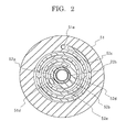
- Figure 2 is a cross section along line A - A of an expansion mechanism of the scroll expander according to Embodiment 1 of the present invention shown in Figure 1.
- a thick portion 52d is disposed on an inner end portion of the spiral tooth 52c of the orbiting scroll 52, and the eccentric shaft bearing portion 52b into which the crank portion 8b is inserted is formed so as to pass through the thick portion 52d.
- An inner seal groove 52g is formed on the base plate 51a of the orbiting scroll 52 outside the eccentric shaft bearing portion 52b, and the inner seal 22b is mounted into the inner seal groove 52g.
- a suction port 51d for sucking in refrigerant and a discharge port 51e for discharging refrigerant are opened through the base plate 51c of the fixed scroll 51.
- the suction port 51d has a generally elongated slot shape in order to ensure aperture area, and is connected to the expansion suction pipe 13.
- a notched portion 52e is also disposed on the thick portion 52d in order to reduce blocked area of the suction port 51d during the pivoting motion.
- the discharge port 51e is opened at a position that does not interfere with the outer end portion of the spiral tooth 52c of the orbiting scroll 52, and is connected to the expansion discharge pipe 15.
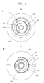
- Figure 3 is a plan showing an auxiliary compression mechanism of the scroll expander according to Embodiment 1 of the present invention, Figure 3(a) being a plan of the fixed scroll of the auxiliary compression mechanism and Figure 3(b) being a plan of the orbiting scroll of the auxiliary compression mechanism.
- the spiral teeth 61c and 62c of the auxiliary compression mechanism 6 have a winding direction identical to that of the expansion mechanism 5 such that when the orbiting scroll 62 is integrated so as to be back to back with the orbiting scroll 52 of the expansion mechanism 5 and performs the pivoting motion, compression can occur in the former and expansion in the latter.
- the eccentric shaft bearing portion 62b into which the crank portion 8b is inserted is formed so as to pass through a thick portion 62d of the orbiting scroll 62, and a suction port 61d for sucking in refrigerant and a discharge port 61e for discharging refrigerant are opened through the base plate 61a of the fixed scroll 61.
- the discharge port 61e has a generally elongated slot shape in order to ensure aperture area, and is connected to the auxiliary compression discharge pipe 14.
- a notched portion 62e is also disposed on the thick portion 62d in order to reduce blocked area of the discharge port 61e during the pivoting motion.
- the suction port 61d is opened at a position that does not interfere with the outer end portion of the spiral tooth 62c of the orbiting scroll 62, and is connected to the auxiliary compression suction pipe 12.
- Tip seal grooves 61f and 62f for mounting the tip seals are formed on tip surfaces of the spiral teeth 61c and 62c.
- An inner seal groove 62g for mounting the inner seal 22a is formed on the base plate 62a of the orbiting scroll 62 outside the eccentric shaft bearing portion 62b.
- An outer seal groove 61g for mounting the outer seal 23 is formed on the base plate 61a of the fixed scroll 61 outside the spiral tooth 61c.
- Figure 4 is a circuit diagram showing basic configuration of a refrigerating cycle using the scroll expander according to Embodiment 1 of the present invention.
- a refrigerant having a high-pressure side that is supercritical, such as carbon dioxide, is used.
- a main compression mechanism 11a that is driven by an electrically powered mechanism 11b of a main compressor 11 is installed in a stage preceding the auxiliary compression mechanism 6 that is driven by the expansion mechanism 5 of the scroll expander 1, and an evaporator 4 that heats the refrigerant is installed in a stage preceding the main compression mechanism 11a.
- a gas cooler 2 that cools the refrigerant is installed in a stage subsequent to the auxiliary compression mechanism 6, and the expansion mechanism 5 of the scroll expander 1 and an expansion valve 3 are disposed in parallel in a stage subsequent to the gas cooler 2.
- Refrigerant that has been pressurized in the main compression mechanism 11a of the main compressor 11 is pressurized further by the auxiliary compression mechanism 6 of the scroll expander 1.
- Refrigerant that has been pressurized in the auxiliary compression mechanism 6 is cooled by the gas cooler 2, then a portion is sent to the expansion mechanism 5 of the scroll expander 1 to be expanded and decompressed.
- the expansion valve 3 is disposed in parallel with the expansion mechanism 5 of the scroll expander 1 in order to adjust quantities of flow passing through the expansion mechanism 5 and to ensure differential pressure at startup, and the remaining refrigerant is sent to the expansion valve 3 to be expanded and decompressed.
- the refrigerant expands isentropically, and expansion power is transmitted from the expansion mechanism 5 through the main shaft 8 to the auxiliary compression mechanism 6 and is used for auxiliary compression work.
- Refrigerant that has been expanded in the expansion mechanism 5 is heated by the evaporator 4, then returns to the main compression mechanism 11a of the main compressor 11.
- Figure 5 is a Mollier diagram showing changes in quantities of state of a refrigerant in the refrigerating cycle using the scroll expander according to Embodiment 1 of the present invention.
- the vertical axis is pressure P
- the horizontal axis is enthalpy h.
- Embodiment 1 of the present invention a portion of the compression process of the refrigerating cycle is undertaken by the compression mechanism 11b of the main compressor 11, and a remainder of the compression process is undertaken by the auxiliary compression mechanism 6 of the scroll expander 1. Compression power proportionate to the difference in enthalpy h d - h d ' in the auxiliary compression mechanism 6 is provided by recovered power proportionate to h b ' - h b .
- Figure 6 is a schematic diagram for explaining a relationship between quantity of flow and rotational frequency in general expansion-compression mechanisms.
- N E Ge ⁇ v ei Vei
- Rotational frequency Nc at the auxiliary compression mechanism 6 can be expressed as in Mathematical Formula 2.
- N c Gc ⁇ v cs Vcs
- a ratio of stroke volumes ⁇ vec of the expansion mechanism 5 and the auxiliary compression mechanism 6 shown in Mathematical Formula 3 is constant if equipment dimensions are fixed relative to certain design conditions. If operating outside the design conditions, it becomes necessary to adjust a ratio between quantities of volume flow (Gev ei /Gcv cs ) so as to satisfy Mathematical Formula 3.
- the quantity of mass flow Ge is normally adjusted by a means such as a bypass like the expansion valve 3, etc.
- the quantity of flow that is made to bypass is a quantity of non-recoverable flow from which expansion power cannot be recovered and effective power recovery decreases, it is necessary to suppress the quantity of bypass flow as much as possible.
- Figure 7 is a general cross section of the expansion mechanism and the auxiliary compression mechanism of the scroll expander according to Embodiment 1 of the present invention.
- Tip seals 21 that partition off the auxiliary compression chamber 6a are mounted to the spiral teeth 61c and 62c of the auxiliary compression mechanism 6.
- An outer seal 23 is also disposed on the base plate 61a of the fixed scroll 61 of the auxiliary compression mechanism 6 outside the spiral tooth 61c.
- inner seals 22a and 22b are disposed outside the eccentric shaft bearing portions 52b and 62b of the orbiting scrolls 52 and 62.
- an outer portion of the base plate 51a of the fixed scroll 51 and an outer portion of the base plate 52a of the orbiting scroll 52 are configured so as to come into contact.
- Figure 8 is a cross section in which a vicinity of a tip seal is enlarged in order to explain a contact seal function of the tip seals.
- the tip seal 21 is pressed from the left and from below, which are on a high-pressure side, as indicated by the arrows, due to differential pressure on two sides of the auxiliary compression chamber 6a that are partitioned off. For this reason, the tip seal 21 is pressed against a wall to the right and a base plate above inside the tip seal groove 62f that is disposed for mounting the tip seal 21, forming a contact seal between the orbiting scroll 62 and the fixed scroll 61.
- Contact seal actions of the inner seals 22a and 22b and the outer seal 23 are also similar to the contact seal action of the tip seals 21.
- the expansion mechanism 5 undertakes an expansion process from a high pressure Ph (pressure at point c) to a low pressure Pl (pressure at point b), and the auxiliary compression mechanism 6 undertakes a compression process from an intermediate pressure Pm (pressure at point d') to the high pressure Ph (pressure at point d ⁇ pressure at point c).
- the high pressure Ph acts on both a central portion of the expansion chamber 5a and a central portion of the auxiliary compression chamber 6a
- the low pressure Pl acts on an outer portion of the expansion chamber 5a and the intermediate pressure Pm on an outer portion of the auxiliary compression chamber 6a.
- the outer seal 23 is disposed on the base plate 61a of the fixed scroll 61 of the auxiliary compression mechanism 6 outside the spiral tooth 61c in order to seal off differential pressure between the outer portion of the auxiliary compression chamber 6a (Pm) and the inside of the sealed vessel 10 (Pl).
- the inner seals 22a and 22b are disposed outside the eccentric shaft bearing portions 52b and 62b of the orbiting scrolls 52 and 62 in order to seal off differential pressure between the central portion of the expansion chamber 5a (Ph) and the inside of the sealed vessel 10 (Pl) and between the central portion of the auxiliary compression chamber 6a (Ph) and the inside of the sealed vessel 10 (Pl).
- outer seals 23 must be disposed on an outer portion of the expansion mechanism 5, which is at the low pressure Pl, and an outer portion of the auxiliary compression mechanism 6, which is at the intermediate pressure Pm. If the inside of the sealed vessel 10 is set to the intermediate pressure Pm, an outer seal 23 must be disposed on an outer portion of the expansion mechanism 5, which is at the low pressure Pl, and inner seals 22a and 22b disposed on a central portion of the expansion mechanism 5 and a central portion of the auxiliary compression mechanism 6, which are at the high pressure Ph.
- the number of seals is equal to or less than when the inside of the sealed vessel 10 is set to the low pressure Pl.
- the inside of the sealed vessel 10 is set to the high pressure Ph or set to the intermediate pressure Pm, it is necessary to increase the thickness of the walls of the sealed vessel 10 more than if the inside of the sealed vessel 10 is set to the low pressure Pl in order to ensure pressure tolerance of the sealed vessel 10 relative to the high pressure Ph or to the intermediate pressure Pm, which is close to the high pressure Ph.
- the inside of the sealed vessel 10 can be set to the low pressure Pl, enabling manufacturing costs for the scroll expander 1 to be reduced.
- a center of the outer seal groove 61g of the outer seal 23 that separates the outer portion of the expansion chamber 5a that is at the low pressure Pl and the outer portion of the auxiliary compression chamber 6a that is at the intermediate pressure Pm is offset from the coordinate center of the spiral tooth 61c of the fixed scroll 61 toward a center of a circumscribing circle. Because of this, the diameter of the outer seal groove 61g is reduced so as to suppress the area over which the auxiliary compression mechanism 6 is subjected to the intermediate pressure Pm, preventing pressing forces on the tip surfaces of the spiral teeth 51c and 52c and the outer portions of the base plates 51a and 52a of the expansion mechanism 5 from becoming excessive.
- the arrows represent distribution of axial differential pressure forces acting on the orbiting scrolls 52 and 62 using the low pressure Pl as a reference.
- the differential pressure forces at the central portions of the orbiting scrolls 52 and 62 are equal to Ph - Pl on both an expansion mechanism 5 side and an auxiliary compression mechanism 6 side.
- the differential pressure forces at outer portions of the orbiting scrolls 52 and 62 are zero on the expansion mechanism 5 side and Pm - Pl on the auxiliary compression mechanism 6 side.
- the orbiting scrolls 52 and 62 are subjected to a pressing force F directed downward in a direction of the shaft 8 (a force directed from the auxiliary compression mechanism 6 side toward the expansion mechanism 5 side), and the pressing force F is borne by the tip surfaces of the spiral teeth 51c and 52c and the base plate 51a and 52a of the expansion mechanism 5.
- axial positions of the orbiting scrolls are determined by points that support axial force due to the pressure of the refrigerant, and gaps that correspond to assembly clearance arise on surfaces on opposite sides of the orbiting scrolls from the direction of pressure. For this reason, leakage may arise with the expansion chamber 5a or within the auxiliary compression chamber 6a where pressure differs.
- the pressing force F can be supported over a wider area, suppressing absolute values of the surface pressure acting on the tooth ends of the spiral teeth 51c and 52c and amplitude of fluctuations during working pressure changes.
- pivoting radii r of the expansion mechanism 5 and the auxiliary compression mechanism 6 have a relationship such as that shown in Mathematical Formula 4.
- the pivoting radii r are equal in the expansion mechanism 5 and the auxiliary compression mechanism 6.
- the spiral tooth thickness t is greater in the spiral teeth 51c and 52c of the expansion mechanism 5 than in the spiral teeth 61c and 62c of the auxiliary compression mechanism 6.
- the spiral tooth pitch p is also correspondingly greater in the spiral teeth 51c and 52c of the expansion mechanism 5 than in the spiral teeth 61c and 62c of the auxiliary compression mechanism 6.
- spiral tooth thickness t is greater in the spiral teeth 51c and 52c of the expansion mechanism 5 than in the spiral teeth 61c and 62c of the auxiliary compression mechanism 6, strength can be ensured in the spiral teeth 51c and 52c of the expansion mechanism 5 where differential pressure before and after expansion is greater than differential pressure before and after compression in the auxiliary compression mechanism 6.
- Figure 9 is a longitudinal section showing configuration of a scroll expander according to Embodiment 2 of the present invention.
- tip seals 21 were mounted to tips of spiral teeth 61c and 62c of an auxiliary compression mechanism 6, and orbiting scrolls 52 and 62 were configured so as to be pressed against a fixed scroll 51 of an expansion mechanism 5.
- tip seals 21 are mounted to tips of spiral teeth 51c and 52c of an expansion mechanism 5, and orbiting scrolls 52 and 62 are configured so as to be pressed against a fixed scroll 61 of an auxiliary compression mechanism 6.
- tip seals 21 are not mounted to tips of spiral teeth 61c and 62c of the auxiliary compression mechanism 6.
- the rest of the configuration and functions of the scroll expander 1A according to Embodiment 2 of the present invention are similar to those of the scroll expander 1 shown in Embodiment 1.
- Figure 10 is a circuit diagram showing basic configuration of a refrigerating cycle using the scroll expander according to Embodiment 2 of the present invention.
- a refrigerant having a high-pressure side that is supercritical, such as carbon dioxide, is assumed.
- a main compression mechanism 11a that is driven by an electrically powered mechanism 11b of a main compressor 11 is installed in a stage subsequent to the auxiliary compression mechanism 6 that is driven by the expansion mechanism 5 of the scroll expander 1A.
- a gas cooler 2 that cools the refrigerant is installed in a stage subsequent to the main compression mechanism 11a, and the expansion mechanism 5 of the scroll expander 1A and an expansion valve 3 are disposed in parallel in a stage subsequent to the gas cooler 2.
- an evaporator 4 that heats the refrigerant is installed in a stage preceding the auxiliary compression mechanism 6.
- Refrigerant that has been pressurized in the auxiliary compression mechanism 6 that is driven by the expansion mechanism 5 of the scroll expander 1A is pressurized further by the main compression mechanism 11a that is driven by the electrically powered mechanism 11b of the main compressor 11.
- Refrigerant that has been pressurized in the main compression mechanism 11a is cooled by the gas cooler 2, then a portion is sent to the expansion mechanism 5 of the scroll expander 1A to be expanded and decompressed.
- the expansion valve 3 is disposed in parallel with the expansion mechanism 5 of the scroll expander 1A in order to adjust quantities of flow passing through the expansion mechanism 5 and to ensure differential pressure at startup, and the remaining refrigerant is sent to the expansion valve 3 to be expanded and decompressed.
- the refrigerant expands isentropically, and expansion power is transmitted from the expansion mechanism 5 through the main shaft 8 to the auxiliary compression mechanism 6 and is used for auxiliary compression work.
- Refrigerant that has been expanded in the expansion mechanism 5 is heated by the evaporator 4, then returns to the auxiliary compression mechanism 6 of the scroll expander 1A.
- Figure 11 is a Mollier diagram showing changes in quantities of state of a refrigerant in the refrigerating cycle using the scroll expander according to Embodiment 2 of the present invention.
- the vertical axis is pressure
- the horizontal axis is enthalpy.
- refrigerant that has been cooled from point d to point c by exchanging heat in the gas cooler 2 changes from point c to point b due to isentropic expansion in the expansion mechanism 5.
- heat is exchanged in the evaporator 4, and refrigerant gas that has been heated from point b to point a is compressed from point a to point a' by the auxiliary compression mechanism 6 of the scroll expander 1A, then compressed from point a' to point d by the main compression mechanism 11a of the main compressor 11.
- Embodiment 2 of the present invention a portion of the compression process of the refrigerating cycle is undertaken by the compression mechanism 11b of the main compressor 11, and a remainder of the compression process is undertaken by the auxiliary compression mechanism 6 of the scroll expander 1A.
- Compression power proportionate to a difference in enthalpy h a ' - h a in the auxiliary compression mechanism 6 is provided by recovered power proportionate to h b ' - h b .
- Embodiment 2 of the present invention a portion of the compression process of the refrigerating cycle is also undertaken by the main compression mechanism 11a driven by the electrically powered mechanism 11b and the remainder is undertaken by the auxiliary compression mechanism 6 of the scroll expander 1A driven by recovered power. Because of this, decreases in recovery effects due to bypassing can be suppressed proportionately more than if all of the compression process of the refrigerating cycle is undertaken by the auxiliary compression mechanism 6 of the scroll expander 1A since adjustment of compression power by increasing pressure in the auxiliary compression mechanism 6 is possible.
- Figure 12 is a general cross section of the expansion mechanism and an auxiliary compression mechanism of the scroll expander according to Embodiment 2 of the present invention.
- Tip seals 21 that partition off the expansion chamber 5a are mounted to the spiral teeth 51c and 52c of the expansion mechanism 5.
- Inner seals 22a and 22b are installed outside the eccentric shaft bearing portions 52b and 62b of the orbiting scrolls 52 and 62.
- an outer portion of the base plate 61a of the fixed scroll 61 and an outer portion of the base plate 62a of the orbiting scroll 62 are configured to come into contact.
- the expansion mechanism 5 undertakes an expansion process from a high pressure Ph (pressure at point c) to a low pressure Pl (pressure at point b), and the auxiliary compression mechanism 6 undertakes a compression process from the low pressure Pl (pressure at point a ⁇ pressure at point b) to an intermediate pressure Pm (pressure at point a').
- the high pressure Ph acts on the central portion of the expansion chamber 5a
- the intermediate pressure Pm on a central portion of the auxiliary compression chamber 6a
- the low pressure Pl acts on both the outer portion of the expansion chamber 5a and the outer portion of the auxiliary compression chamber 6a.
- the inside of the sealed vessel 10 can be set to the low pressure Pl, and it is no longer necessary to increase the thickness of the walls of the sealed vessel 10 as much as if the inside of the sealed vessel 10 is at the high pressure Ph or the intermediate pressure Pm, enabling manufacturing costs for the scroll expander 1A to be reduced.
- the arrows represent distribution of axial differential pressure forces acting on the orbiting scrolls 52 and 62 using the low pressure Pl as a reference.
- the differential pressure forces at outer portions of the orbiting scrolls 52 and 62 are zero on both the expansion mechanism 5 side and the auxiliary compression mechanism 6 side.
- the differential pressure forces at inner portions of the orbiting scrolls 52 and 62 are Ph - Pl on the expansion mechanism 5 side and Pm - Pl on the auxiliary compression mechanism 6 side.
- the orbiting scrolls 52 and 62 are subjected to a pressing force F directed upward in a direction of the shaft 8 (a force directed from the expansion mechanism 5 side toward the auxiliary compression mechanism 6 side), and the pressing force F is borne by the tip surfaces of the spiral teeth 61c and 62c and the base plate 61a and 62a of the auxiliary compression mechanism 6.
- the auxiliary compression mechanism 6 because the outer portion of the base plate 61a of the fixed scroll 61 and the outer portion of the base plate 62a of the orbiting scroll 62 are configured so as to come into contact, the pressing force F can be supported over a wider area, preventing the surface pressure acting on the tooth ends of the spiral teeth 61c and 62c from becoming excessive.
Landscapes
- Engineering & Computer Science (AREA)
- Mechanical Engineering (AREA)
- General Engineering & Computer Science (AREA)
- Physics & Mathematics (AREA)
- Thermal Sciences (AREA)
- Chemical & Material Sciences (AREA)
- Combustion & Propulsion (AREA)
- Rotary Pumps (AREA)
- Applications Or Details Of Rotary Compressors (AREA)
- Engine Equipment That Uses Special Cycles (AREA)
Abstract
Description
- The present invention relates to a scroll expander in which power is recovered by expanding a refrigerant and is used in compression.
- In conventional scroll expanders, a compression chamber of a compressing means is formed by a first fixed scroll and an orbiting scroll, and at the same time, an expansion chamber of an expanding means is formed by a second fixed scroll and the orbiting scroll. The orbiting scroll is linked to a crankshaft, and is configured so as to be driven to revolve by a motor mounted to the crankshaft (see
Patent Literature 1, for example). - Patent Literature 1:
Japanese Patent Publication No. HEI 07-037857 - However, scroll expanders such as that described above have had to be configured integrally with driving sources such as the motor, etc., making construction complicated. Another problem has been that recovered power is reduced in off-design point operating conditions since quantity of flow or differential pressure of the expansion mechanism must be reduced in order to synchronize the rotational frequencies of the expansion mechanism and the compression mechanism. An additional problem has been that leakage at tip of spiral teeth cannot be suppressed because the expansion chamber and the compression chamber are disposed on two surfaces of the orbiting scroll (pivoting scroll).
- The present invention aims to solve the above problems and an object of the present invention is to provide a scroll expander that is efficient in a wide range of operating conditions by suppressing leakage loss and decreases in recovered power using a simple construction.
- According to one aspect of the present invention, there is provided a scroll expander including: an expansion mechanism that is constituted by an orbiting scroll and a first fixed scroll, and that recovers power by expanding a refrigerant; and an auxiliary compression mechanism that is constituted by an orbiting scroll and a second fixed scroll, and that compresses refrigerant using power recovered by the expansion mechanism, characterized in that a tip seal is mounted only to a spiral tooth of an orbiting scroll and a fixed scroll of one of either the expansion mechanism or the auxiliary compression mechanism.
- According to another aspect of the present invention, there is provided a scroll expander including: an expansion mechanism that is constituted by an orbiting scroll and a first fixed scroll, and that recovers power by expanding a refrigerant; and an auxiliary compression mechanism that is constituted by an orbiting scroll and a second fixed scroll, and that undertakes a portion of a compression process of a refrigerating cycle by compressing refrigerant using power recovered by the expansion mechanism, characterized in that a tip seal is mounted only to a spiral tooth of an orbiting scroll and a fixed scroll of one of either the expansion mechanism or the auxiliary compression mechanism.
- The present invention can provide a scroll expander that is efficient in a wide range of operating conditions by suppressing leakage loss and decreases in recovered power using a simple construction.
-
- Figure 1 is a longitudinal section showing configuration of a scroll expander according to
Embodiment 1 of the present invention; - Figure 2 is a lateral section of an expansion mechanism of the scroll expander according to
Embodiment 1 of the present invention; - Figure 3 is a plan showing an auxiliary compression mechanism of the scroll expander according to
Embodiment 1 of the present invention; - Figure 4 is a circuit diagram showing basic configuration of a refrigerating cycle using the scroll expander according to
Embodiment 1 of the present invention; - Figure 5 is a Mollier diagram showing changes in quantities of state of a refrigerant in the refrigerating cycle using the scroll expander according to
Embodiment 1 of the present invention; - Figure 6 is a schematic diagram for explaining a relationship between quantity of flow and rotational frequency in general expansion-compression mechanisms;
- Figure 7 is a general cross section of the expansion mechanism and the auxiliary compression mechanism of the scroll expander according to
Embodiment 1 of the present invention; - Figure 8 is a cross section for explaining a general contact seal function of a tip seal;
- Figure 9 is a longitudinal section showing configuration of a scroll expander according to
Embodiment 2 of the present invention; - Figure 10 is a circuit diagram showing basic configuration of a refrigerating cycle using the scroll expander according to
Embodiment 2 of the present invention; - Figure 11 is a Mollier diagram showing changes in quantities of state of a refrigerant in the refrigerating cycle using the scroll expander according to
Embodiment 2 of the present invention; and - Figure 12 is a general cross section of the expansion mechanism and an auxiliary compression mechanism of the scroll expander according to
Embodiment 2 of the present invention. - Figure 1 is a longitudinal section showing configuration of a scroll expander according to
Embodiment 1 of the present invention. In the figure, portions allocated identical numbering are identical or correspond to each other, and this will be constant throughout the specification. - In Figure 1, an
expansion mechanism 5 is installed in a lower portion inside a sealedvessel 10 of a scroll expander 1, and anauxiliary compression mechanism 6 is installed above theexpansion mechanism 5. Theexpansion mechanism 5 is constituted by: a fixed scroll 51 (first fixed scroll) having aspiral tooth 51c formed on abase plate 51a; and anorbiting scroll 52 having aspiral tooth 52c formed on abase plate 52a, thespiral tooth 51c of thefixed scroll 51 and thespiral tooth 52c of the orbitingscroll 52 being disposed so as to mesh with each other. Theauxiliary compression mechanism 6 is constituted by: a fixed scroll 61 (second fixed scroll) having aspiral tooth 61c formed on abase plate 61a; and anorbiting scroll 62 having aspiral tooth 62c formed on abase plate 62a, thespiral tooth 61c of thefixed scroll 61 and thespiral tooth 62c of the orbitingscroll 62 being disposed so as to mesh with each other. - A
shaft 8 is held rotatably at two ends byshaft bearing portions fixed scroll 51 of theexpansion mechanism 5 and thefixed scroll 61 of theauxiliary compression mechanism 6, respectively. Eccentricshaft bearing portions scroll 52 of theexpansion mechanism 5 and the orbitingscroll 62 of theauxiliary compression mechanism 6, respectively, are penetrated and supported by acrank portion 8b fitted onto theshaft 8 so as to enable pivoting motion. - An
expansion suction pipe 13 that sucks in refrigerant and anexpansion discharge pipe 15 that discharges expanded refrigerant are installed on side surfaces of the sealedvessel 10 outside theexpansion mechanism 5. Similarly, an auxiliarycompression suction pipe 12 that sucks in refrigerant is installed on an upper surface of the sealedvessel 10 above theauxiliary compression mechanism 6, and an auxiliarycompression discharge pipe 14 that discharges compressed refrigerant is installed on a side surface of the sealedvessel 10 outside theauxiliary compression mechanism 6. - In the
auxiliary compression mechanism 6,tip seals 21 that partition off anauxiliary compression chamber 6a that is formed by thespiral tooth 61c of thefixed scroll 61 and thespiral tooth 62c of the orbitingscroll 62 are mounted onto tips of thespiral teeth fixed scroll 61 and theorbiting scroll 62, respectively. Aninner seal 22a that forms a seal between the orbitingscroll 62 and thefixed scroll 61 is disposed outside the eccentricshaft bearing portion 62b of the orbitingscroll 62 on a surface that faces thefixed scroll 61. In addition, anouter seal 23 that forms a seal between the orbitingscroll 62 and thefixed scroll 61 is disposed outside thespiral tooth 61c of thefixed scroll 61 on a surface that faces theorbiting scroll 52. - Similarly, in the
expansion mechanism 5, aninner seal 22b that forms a seal between theorbiting scroll 52 and thefixed scroll 51 in a similar manner to theauxiliary compression mechanism 6 is disposed outside the eccentricshaft bearing portion 52b of theorbiting scroll 52 on a surface that faces thefixed scroll 51. However,tip seals 21 are not mounted to tips of thespiral teeth fixed scroll 51 and theorbiting scroll 52. Nor is anouter seal 23 disposed outside thespiral tooth 51c in thefixed scroll 51 on a surface that faces the orbitingscroll 52. - The
orbiting scroll 52 of theexpansion mechanism 5 and theorbiting scroll 62 of theauxiliary compression mechanism 6 are integrated by bonding elements such as pins, etc., and autorotation is corrected by an Oldhamring 7 that is disposed on theauxiliary compression mechanism 6.Counterweights shaft 8 in order to cancel out centrifugal force that is generated by the pivoting motion of the orbitingscrolls orbiting scroll 52 of theexpansion mechanism 5 and theorbiting scroll 62 of theauxiliary compression mechanism 6 may also be formed integrally in a shape in which thebase plates - In the
expansion mechanism 5, power is generated inside theexpansion chamber 5a that is formed by thespiral tooth 51c of thefixed scroll 51 and thespiral tooth 52c of the orbitingscroll 52 by expansion of high-pressure refrigerant that has been sucked in through theexpansion suction pipe 13. Refrigerant that has expanded inside theexpansion chamber 5a and decompressed is discharged outside the sealedvessel 10 through theexpansion discharge pipe 15. Refrigerant sucked in through the auxiliarycompression suction pipe 12 is compressed and pressurized inside theauxiliary compression chamber 6a that is formed by thespiral tooth 61c of thefixed scroll 61 and thespiral tooth 62c of the orbitingscroll 62 of theauxiliary compression mechanism 6 by the power generated in theexpansion mechanism 5. Refrigerant that has been compressed and pressurized inside theauxiliary compression chamber 6a is discharged outside the sealedvessel 10 through the auxiliarycompression discharge pipe 14. - Figure 2 is a cross section along line A - A of an expansion mechanism of the scroll expander according to
Embodiment 1 of the present invention shown in Figure 1. - A
thick portion 52d is disposed on an inner end portion of thespiral tooth 52c of the orbitingscroll 52, and the eccentricshaft bearing portion 52b into which thecrank portion 8b is inserted is formed so as to pass through thethick portion 52d. Aninner seal groove 52g is formed on thebase plate 51a of the orbitingscroll 52 outside the eccentricshaft bearing portion 52b, and theinner seal 22b is mounted into theinner seal groove 52g. - A
suction port 51d for sucking in refrigerant and adischarge port 51e for discharging refrigerant are opened through thebase plate 51c of thefixed scroll 51. Thesuction port 51d has a generally elongated slot shape in order to ensure aperture area, and is connected to theexpansion suction pipe 13. A notchedportion 52e is also disposed on thethick portion 52d in order to reduce blocked area of thesuction port 51d during the pivoting motion. Thedischarge port 51e is opened at a position that does not interfere with the outer end portion of thespiral tooth 52c of theorbiting scroll 52, and is connected to theexpansion discharge pipe 15. - Figure 3 is a plan showing an auxiliary compression mechanism of the scroll expander according to
Embodiment 1 of the present invention, Figure 3(a) being a plan of the fixed scroll of the auxiliary compression mechanism and Figure 3(b) being a plan of the orbiting scroll of the auxiliary compression mechanism. As shown in Figure 3, thespiral teeth auxiliary compression mechanism 6 have a winding direction identical to that of theexpansion mechanism 5 such that when theorbiting scroll 62 is integrated so as to be back to back with theorbiting scroll 52 of theexpansion mechanism 5 and performs the pivoting motion, compression can occur in the former and expansion in the latter. - In a similar manner to the orbiting
scroll 52 of theexpansion mechanism 5, the eccentricshaft bearing portion 62b into which thecrank portion 8b is inserted is formed so as to pass through athick portion 62d of theorbiting scroll 62, and asuction port 61d for sucking in refrigerant and adischarge port 61e for discharging refrigerant are opened through thebase plate 61a of thefixed scroll 61. Thedischarge port 61e has a generally elongated slot shape in order to ensure aperture area, and is connected to the auxiliarycompression discharge pipe 14. A notchedportion 62e is also disposed on thethick portion 62d in order to reduce blocked area of thedischarge port 61e during the pivoting motion. Thesuction port 61d is opened at a position that does not interfere with the outer end portion of thespiral tooth 62c of the orbitingscroll 62, and is connected to the auxiliarycompression suction pipe 12. -
Tip seal grooves spiral teeth inner seal groove 62g for mounting theinner seal 22a is formed on thebase plate 62a of the orbitingscroll 62 outside the eccentricshaft bearing portion 62b. Anouter seal groove 61g for mounting theouter seal 23 is formed on thebase plate 61a of the fixedscroll 61 outside thespiral tooth 61c. - Figure 4 is a circuit diagram showing basic configuration of a refrigerating cycle using the scroll expander according to
Embodiment 1 of the present invention. InEmbodiment 1 of the present invention, it is assumed that a refrigerant having a high-pressure side that is supercritical, such as carbon dioxide, is used. - In Figure 4, a
main compression mechanism 11a that is driven by an electricallypowered mechanism 11b of amain compressor 11 is installed in a stage preceding theauxiliary compression mechanism 6 that is driven by theexpansion mechanism 5 of thescroll expander 1, and anevaporator 4 that heats the refrigerant is installed in a stage preceding themain compression mechanism 11a. On the other hand, agas cooler 2 that cools the refrigerant is installed in a stage subsequent to theauxiliary compression mechanism 6, and theexpansion mechanism 5 of thescroll expander 1 and anexpansion valve 3 are disposed in parallel in a stage subsequent to thegas cooler 2. - Refrigerant that has been pressurized in the
main compression mechanism 11a of themain compressor 11 is pressurized further by theauxiliary compression mechanism 6 of thescroll expander 1. Refrigerant that has been pressurized in theauxiliary compression mechanism 6 is cooled by thegas cooler 2, then a portion is sent to theexpansion mechanism 5 of thescroll expander 1 to be expanded and decompressed. Theexpansion valve 3 is disposed in parallel with theexpansion mechanism 5 of thescroll expander 1 in order to adjust quantities of flow passing through theexpansion mechanism 5 and to ensure differential pressure at startup, and the remaining refrigerant is sent to theexpansion valve 3 to be expanded and decompressed. In theexpansion mechanism 5, the refrigerant expands isentropically, and expansion power is transmitted from theexpansion mechanism 5 through themain shaft 8 to theauxiliary compression mechanism 6 and is used for auxiliary compression work. Refrigerant that has been expanded in theexpansion mechanism 5 is heated by theevaporator 4, then returns to themain compression mechanism 11a of themain compressor 11. - Figure 5 is a Mollier diagram showing changes in quantities of state of a refrigerant in the refrigerating cycle using the scroll expander according to
Embodiment 1 of the present invention. In Figure 5, the vertical axis is pressure P, and the horizontal axis is enthalpy h. - As shown in Figure 5, refrigerant that has been cooled from point d to point c by exchanging heat in the
gas cooler 2, expands isenthalpically in a decompression mechanism formed by a restrictor such as an expansion valve as indicated by point c to point b'. However, this becomes point c to point b in theexpansion mechanism 5 due to isentropic expansion. For this reason, an amount proportionate to a difference hb' - hb between enthalpy hb' at point b' and enthalpy hb at point b can be recovered as expansion power. After expansion, heat is exchanged in theevaporator 4, and refrigerant gas that has been heated from point b to point a is compressed from point a to point d' by themain compression mechanism 11a of themain compressor 11, then compressed from point d' to point d by theauxiliary compression mechanism 6 of thescroll expander 1. As described above, inEmbodiment 1 of the present invention, a portion of the compression process of the refrigerating cycle is undertaken by thecompression mechanism 11b of themain compressor 11, and a remainder of the compression process is undertaken by theauxiliary compression mechanism 6 of thescroll expander 1. Compression power proportionate to the difference in enthalpy hd - hd' in theauxiliary compression mechanism 6 is provided by recovered power proportionate to hb' - hb. - Figure 6 is a schematic diagram for explaining a relationship between quantity of flow and rotational frequency in general expansion-compression mechanisms.
- As shown in Figure 6, when there is an
auxiliary compression mechanism 6 that is driven by anexpansion mechanism 5, if we let quantity of mass flow of refrigerant passing through theexpansion mechanism 5 be Ge, quantity of through flow at theauxiliary compression mechanism 6 be Gc, suction stroke volume of theexpansion mechanism 5 be Vei, and suction stroke volume of theauxiliary compression mechanism 6 be Vcs, and let refrigerant specific volume at the entrance of theexpansion mechanism 5 be Vei, and refrigerant specific volume at the entrance of the compression mechanism Cs be Vcs, then rotational frequency NE determined by theexpansion mechanism 5 can be expressed as inMathematical Formula 1. -

- Rotational frequency Nc at the
auxiliary compression mechanism 6 can be expressed as inMathematical Formula 2. -

- Consequently, since NE = Nc is a condition for matching the rotational frequencies of the
expansion mechanism 5 and theauxiliary compression mechanism 6,Mathematical Formula 3 must be satisfied. -

- A ratio of stroke volumes σvec of the
expansion mechanism 5 and theauxiliary compression mechanism 6 shown inMathematical Formula 3 is constant if equipment dimensions are fixed relative to certain design conditions. If operating outside the design conditions, it becomes necessary to adjust a ratio between quantities of volume flow (Gevei/Gcvcs) so as to satisfyMathematical Formula 3. If all of the compression process of the refrigerating cycle is undertaken by the auxiliary compression mechanism 6 (in that case, it is necessary to use a separate driving source for theauxiliary compression mechanism 6 in addition to the recovered power from the expansion mechanism 5), because specific volumes vei and Vcs at the entrances of theexpansion mechanism 5 and theauxiliary compression mechanism 6, respectively, are determined by the operating conditions, the quantity of mass flow Ge is normally adjusted by a means such as a bypass like theexpansion valve 3, etc. Here, because the quantity of flow that is made to bypass is a quantity of non-recoverable flow from which expansion power cannot be recovered and effective power recovery decreases, it is necessary to suppress the quantity of bypass flow as much as possible. - As shown in Figure 5, if a portion (point a to point d') of the compression process of the refrigerating cycle is undertaken by the
main compression mechanism 11a driven by the electricallypowered mechanism 11b and the remainder of the compression process (point d' to point d) is undertaken by theauxiliary compression mechanism 6 driven by recovered power, changes in the specific volume Vcs at the entrance of theauxiliary compression mechanism 6 are dependent on the pressure at point d'. Thus, even if the specific volumes at point c and point a are determined by the operating conditions, it is possible to adjust the specific volume Vcs at the entrance of theauxiliary compression mechanism 6 for the purpose of rotational frequency matching. However, because driving of theauxiliary compression mechanism 6 is performed only by theexpansion mechanism 5, power matching so as to supply compression power using recovered power is also required. There is a lower limit to the pressure at point b' in Figure 5, and there is also a limit to the adjustment of the specific volume Vcs at the entrance of theauxiliary compression mechanism 6 using the pressure at point b'. Consequently, after power has been balanced between theexpansion mechanism 5 and theauxiliary compression mechanism 6, adjustment of the quantity of through flow Ge of theexpansion mechanism 5 must be performed by bypassing refrigerant through theexpansion valve 3 that is disposed in parallel with theexpansion mechanism 5 in order to satisfy the conditions for rotational frequency matching inMathematical Formula 3. - As explained above, because adjustment of rotational frequency using specific volume Vcs at the entrance of the
auxiliary compression mechanism 6 and adjustment of compression power by increasing pressure in theauxiliary compression mechanism 6 can be used in combination if a portion of the compression process of the refrigerating cycle is undertaken by themain compression mechanism 11a that is driven by the electricallypowered mechanism 11b and the remainder of the compression process is undertaken by theauxiliary compression mechanism 6 of thescroll expander 1 that is driven by recovered power, decreases in recovery effects due to bypassing can be suppressed more than if all of the compression process of the refrigerating cycle is undertaken by theauxiliary compression mechanism 6 of thescroll expander 1. - Figure 7 is a general cross section of the expansion mechanism and the auxiliary compression mechanism of the scroll expander according to
Embodiment 1 of the present invention. - Tip seals 21 that partition off the
auxiliary compression chamber 6a are mounted to thespiral teeth auxiliary compression mechanism 6. Anouter seal 23 is also disposed on thebase plate 61a of the fixedscroll 61 of theauxiliary compression mechanism 6 outside thespiral tooth 61c. In addition,inner seals shaft bearing portions expansion mechanism 5, an outer portion of thebase plate 51a of the fixedscroll 51 and an outer portion of thebase plate 52a of the orbitingscroll 52 are configured so as to come into contact. - Figure 8 is a cross section in which a vicinity of a tip seal is enlarged in order to explain a contact seal function of the tip seals.
- In Figure 8, the
tip seal 21 is pressed from the left and from below, which are on a high-pressure side, as indicated by the arrows, due to differential pressure on two sides of theauxiliary compression chamber 6a that are partitioned off. For this reason, thetip seal 21 is pressed against a wall to the right and a base plate above inside thetip seal groove 62f that is disposed for mounting thetip seal 21, forming a contact seal between the orbitingscroll 62 and the fixedscroll 61. Contact seal actions of theinner seals outer seal 23 are also similar to the contact seal action of the tip seals 21. - In
Embodiment 1 of the present invention, theexpansion mechanism 5 undertakes an expansion process from a high pressure Ph (pressure at point c) to a low pressure Pl (pressure at point b), and theauxiliary compression mechanism 6 undertakes a compression process from an intermediate pressure Pm (pressure at point d') to the high pressure Ph (pressure at point d ≈ pressure at point c). For this reason, in the orbiting scrolls 52 and 62, the high pressure Ph acts on both a central portion of theexpansion chamber 5a and a central portion of theauxiliary compression chamber 6a, and the low pressure Pl acts on an outer portion of theexpansion chamber 5a and the intermediate pressure Pm on an outer portion of theauxiliary compression chamber 6a. Because the inside of the sealedvessel 10 is set to the low pressure Pl, theouter seal 23 is disposed on thebase plate 61a of the fixedscroll 61 of theauxiliary compression mechanism 6 outside thespiral tooth 61c in order to seal off differential pressure between the outer portion of theauxiliary compression chamber 6a (Pm) and the inside of the sealed vessel 10 (Pl). Theinner seals shaft bearing portions expansion chamber 5a (Ph) and the inside of the sealed vessel 10 (Pl) and between the central portion of theauxiliary compression chamber 6a (Ph) and the inside of the sealed vessel 10 (Pl). - If the inside of the sealed
vessel 10 is set to the high pressure Ph,outer seals 23 must be disposed on an outer portion of theexpansion mechanism 5, which is at the low pressure Pl, and an outer portion of theauxiliary compression mechanism 6, which is at the intermediate pressure Pm. If the inside of the sealedvessel 10 is set to the intermediate pressure Pm, anouter seal 23 must be disposed on an outer portion of theexpansion mechanism 5, which is at the low pressure Pl, andinner seals expansion mechanism 5 and a central portion of theauxiliary compression mechanism 6, which are at the high pressure Ph. Even if the inside of the sealedvessel 10 is set to the high pressure Ph or set to the intermediate pressure Pm, the number of seals is equal to or less than when the inside of the sealedvessel 10 is set to the low pressure Pl. However, if the inside of the sealedvessel 10 is set to the high pressure Ph or set to the intermediate pressure Pm, it is necessary to increase the thickness of the walls of the sealedvessel 10 more than if the inside of the sealedvessel 10 is set to the low pressure Pl in order to ensure pressure tolerance of the sealedvessel 10 relative to the high pressure Ph or to the intermediate pressure Pm, which is close to the high pressure Ph. Consequently, because theinner seals expansion mechanism 5 and a central portion of theauxiliary compression mechanism 6, and theouter seal 23 is disposed on the outer portion ofauxiliary compression mechanism 6, the inside of the sealedvessel 10 can be set to the low pressure Pl, enabling manufacturing costs for thescroll expander 1 to be reduced. - As shown in Figure 3(a), a center of the
outer seal groove 61g of theouter seal 23 that separates the outer portion of theexpansion chamber 5a that is at the low pressure Pl and the outer portion of theauxiliary compression chamber 6a that is at the intermediate pressure Pm is offset from the coordinate center of thespiral tooth 61c of the fixedscroll 61 toward a center of a circumscribing circle. Because of this, the diameter of theouter seal groove 61g is reduced so as to suppress the area over which theauxiliary compression mechanism 6 is subjected to the intermediate pressure Pm, preventing pressing forces on the tip surfaces of thespiral teeth base plates expansion mechanism 5 from becoming excessive. - In Figure 7, the arrows represent distribution of axial differential pressure forces acting on the orbiting scrolls 52 and 62 using the low pressure Pl as a reference. The differential pressure forces at the central portions of the orbiting scrolls 52 and 62 are equal to Ph - Pl on both an
expansion mechanism 5 side and anauxiliary compression mechanism 6 side. However, the differential pressure forces at outer portions of the orbiting scrolls 52 and 62 are zero on theexpansion mechanism 5 side and Pm - Pl on theauxiliary compression mechanism 6 side. When these differential pressure forces are integrated, the orbiting scrolls 52 and 62 are subjected to a pressing force F directed downward in a direction of the shaft 8 (a force directed from theauxiliary compression mechanism 6 side toward theexpansion mechanism 5 side), and the pressing force F is borne by the tip surfaces of thespiral teeth base plate expansion mechanism 5. - In scroll-type fluid machinery, in the case of both compressors and expanders, and in the case of both single-side spiral constructions that include a spiral tooth on only one surface of an orbiting scroll and double-sided spiral constructions that include spiral teeth on two surfaces of the orbiting scrolls, axial positions of the orbiting scrolls are determined by points that support axial force due to the pressure of the refrigerant, and gaps that correspond to assembly clearance arise on surfaces on opposite sides of the orbiting scrolls from the direction of pressure. For this reason, leakage may arise with the
expansion chamber 5a or within theauxiliary compression chamber 6a where pressure differs. - In a scroll expander according to
Embodiment 1, because the orbiting scrolls 52 and 62 are pressed together against the fixedscroll 51 of theexpansion mechanism 5 by the pressing force F, gaps at the tips of thespiral teeth expansion mechanism 5 are generally eliminated. Because of this, leakage from the tips of thespiral teeth expansion mechanism 5. In particular, because the differential pressure between the intermediate pressure Pm and the low pressure Pl is also increased if the high pressure Ph is an extremely high pressure, as in the case of carbon dioxide, adjustment of the diameter of theouter seal 23 in order to obtain the required pressing force F need only be small and can be achieved without enlarging outside diameter dimensions. On the other hand, gaps arise in theauxiliary compression mechanism 6 between the tip surface of thespiral tooth 62c of the orbitingscroll 62 and thebase plate 61a of the fixedscroll 61 and between thebase plate 62a of the orbitingscroll 62 and the tip surface of thespiral tooth 61c of the fixedscroll 61 of theauxiliary compression mechanism 6. However, because the tip seals 21 are mounted to the tips of thespiral teeth spiral teeth spiral teeth - In the
expansion mechanism 5, because the outer portion of thebase plate 51a of the fixedscroll 51 and the outer portion of thebase plate 52a of the orbitingscroll 52 are configured so as to come into contact, the pressing force F can be supported over a wider area, suppressing absolute values of the surface pressure acting on the tooth ends of thespiral teeth - Now, if p is a spiral tooth pitch, and t is a spiral tooth thickness, then pivoting radii r of the
expansion mechanism 5 and theauxiliary compression mechanism 6 have a relationship such as that shown inMathematical Formula 4. -

- In
Embodiment 1 of the present invention, the pivoting radii r are equal in theexpansion mechanism 5 and theauxiliary compression mechanism 6. However, the spiral tooth thickness t is greater in thespiral teeth expansion mechanism 5 than in thespiral teeth auxiliary compression mechanism 6. The spiral tooth pitch p is also correspondingly greater in thespiral teeth expansion mechanism 5 than in thespiral teeth auxiliary compression mechanism 6. Because the spiral tooth thickness t is greater in thespiral teeth expansion mechanism 5 than in thespiral teeth auxiliary compression mechanism 6, strength can be ensured in thespiral teeth expansion mechanism 5 where differential pressure before and after expansion is greater than differential pressure before and after compression in theauxiliary compression mechanism 6. - In a configuration such as that above, because a portion of the compression process of the refrigerating cycle is undertaken by the
auxiliary compression mechanism 6 of thescroll expander 1, decreases in recovery effects due to bypassing can be suppressed, enabling a scroll expander that is efficient in a wide range of operating conditions to be achieved. Because the orbiting scrolls 52 and 62 are configured so as to be pressed against the fixedscroll 51 of theexpansion mechanism 5 and the tip seals 21 are mounted to thespiral teeth scroll 61 and the orbitingscroll 62 of theauxiliary compression mechanism 6, leakage loss can be reduced. - Because the tip surfaces of the
spiral teeth base plates expansion mechanism 5 are pressed together by performing compression from the intermediate pressure Pm to the high pressure Ph in theauxiliary compression mechanism 6, pressurization in theauxiliary compression mechanism 6 arises after activation, and an entire region of theauxiliary compression mechanism 6 from the outer portion to the central portion is at high pressure Ph before activation, making it possible to achieve ascroll expander 1 having superior activation since tooth end pushing in theexpansion mechanism 5 becomes more reliable. - Figure 9 is a longitudinal section showing configuration of a scroll expander according to
Embodiment 2 of the present invention. - In
Embodiment 1, tip seals 21 were mounted to tips ofspiral teeth auxiliary compression mechanism 6, and orbitingscrolls scroll 51 of anexpansion mechanism 5. In ascroll expander 1A according toEmbodiment 2 of the present invention, as shown in Figure 9, tip seals 21 are mounted to tips ofspiral teeth expansion mechanism 5, and orbitingscrolls scroll 61 of anauxiliary compression mechanism 6. Moreover, tip seals 21 are not mounted to tips ofspiral teeth auxiliary compression mechanism 6. The rest of the configuration and functions of thescroll expander 1A according toEmbodiment 2 of the present invention are similar to those of thescroll expander 1 shown inEmbodiment 1. - Figure 10 is a circuit diagram showing basic configuration of a refrigerating cycle using the scroll expander according to
Embodiment 2 of the present invention. InEmbodiment 2 of the present invention, a refrigerant having a high-pressure side that is supercritical, such as carbon dioxide, is assumed. - In Figure 10, a
main compression mechanism 11a that is driven by an electricallypowered mechanism 11b of amain compressor 11 is installed in a stage subsequent to theauxiliary compression mechanism 6 that is driven by theexpansion mechanism 5 of thescroll expander 1A. Agas cooler 2 that cools the refrigerant is installed in a stage subsequent to themain compression mechanism 11a, and theexpansion mechanism 5 of thescroll expander 1A and anexpansion valve 3 are disposed in parallel in a stage subsequent to thegas cooler 2. On the other hand, anevaporator 4 that heats the refrigerant is installed in a stage preceding theauxiliary compression mechanism 6. - Refrigerant that has been pressurized in the
auxiliary compression mechanism 6 that is driven by theexpansion mechanism 5 of thescroll expander 1A is pressurized further by themain compression mechanism 11a that is driven by the electricallypowered mechanism 11b of themain compressor 11. Refrigerant that has been pressurized in themain compression mechanism 11a is cooled by thegas cooler 2, then a portion is sent to theexpansion mechanism 5 of thescroll expander 1A to be expanded and decompressed. Theexpansion valve 3 is disposed in parallel with theexpansion mechanism 5 of thescroll expander 1A in order to adjust quantities of flow passing through theexpansion mechanism 5 and to ensure differential pressure at startup, and the remaining refrigerant is sent to theexpansion valve 3 to be expanded and decompressed. In theexpansion mechanism 5, the refrigerant expands isentropically, and expansion power is transmitted from theexpansion mechanism 5 through themain shaft 8 to theauxiliary compression mechanism 6 and is used for auxiliary compression work. Refrigerant that has been expanded in theexpansion mechanism 5 is heated by theevaporator 4, then returns to theauxiliary compression mechanism 6 of thescroll expander 1A. - Figure 11 is a Mollier diagram showing changes in quantities of state of a refrigerant in the refrigerating cycle using the scroll expander according to
Embodiment 2 of the present invention. In Figure 11, the vertical axis is pressure, and the horizontal axis is enthalpy. - As shown in Figure 11, refrigerant that has been cooled from point d to point c by exchanging heat in the
gas cooler 2, changes from point c to point b due to isentropic expansion in theexpansion mechanism 5. After expansion, heat is exchanged in theevaporator 4, and refrigerant gas that has been heated from point b to point a is compressed from point a to point a' by theauxiliary compression mechanism 6 of thescroll expander 1A, then compressed from point a' to point d by themain compression mechanism 11a of themain compressor 11. As described above, inEmbodiment 2 of the present invention, a portion of the compression process of the refrigerating cycle is undertaken by thecompression mechanism 11b of themain compressor 11, and a remainder of the compression process is undertaken by theauxiliary compression mechanism 6 of thescroll expander 1A. Compression power proportionate to a difference in enthalpy ha' - ha in theauxiliary compression mechanism 6 is provided by recovered power proportionate to hb' - hb. - In
Embodiment 2 of the present invention, a portion of the compression process of the refrigerating cycle is also undertaken by themain compression mechanism 11a driven by the electricallypowered mechanism 11b and the remainder is undertaken by theauxiliary compression mechanism 6 of thescroll expander 1A driven by recovered power. Because of this, decreases in recovery effects due to bypassing can be suppressed proportionately more than if all of the compression process of the refrigerating cycle is undertaken by theauxiliary compression mechanism 6 of thescroll expander 1A since adjustment of compression power by increasing pressure in theauxiliary compression mechanism 6 is possible. - Figure 12 is a general cross section of the expansion mechanism and an auxiliary compression mechanism of the scroll expander according to
Embodiment 2 of the present invention. - Tip seals 21 that partition off the
expansion chamber 5a are mounted to thespiral teeth expansion mechanism 5.Inner seals shaft bearing portions auxiliary compression mechanism 6, an outer portion of thebase plate 61a of the fixedscroll 61 and an outer portion of thebase plate 62a of the orbitingscroll 62 are configured to come into contact. - In
Embodiment 2 of the present invention, theexpansion mechanism 5 undertakes an expansion process from a high pressure Ph (pressure at point c) to a low pressure Pl (pressure at point b), and theauxiliary compression mechanism 6 undertakes a compression process from the low pressure Pl (pressure at point a ≈ pressure at point b) to an intermediate pressure Pm (pressure at point a'). For this reason, the high pressure Ph acts on the central portion of theexpansion chamber 5a, and the intermediate pressure Pm on a central portion of theauxiliary compression chamber 6a, and the low pressure Pl acts on both the outer portion of theexpansion chamber 5a and the outer portion of theauxiliary compression chamber 6a. Because theinner seals shaft bearing portions expansion chamber 5a and the central portion of theauxiliary compression chamber 6a. Because the pressures that act on the outer portion of theexpansion chamber 5a and the outer portion of theauxiliary compression chamber 6a are both equal to the low pressure Pl, it is not necessary to separate the pressures, andouter seals 23 are not disposed on anexpansion mechanism 5 side or on anauxiliary compression mechanism 6 side. In addition, because theinner seals shaft bearing portions vessel 10 can be set to the low pressure Pl, and it is no longer necessary to increase the thickness of the walls of the sealedvessel 10 as much as if the inside of the sealedvessel 10 is at the high pressure Ph or the intermediate pressure Pm, enabling manufacturing costs for thescroll expander 1A to be reduced. - In Figure 12, the arrows represent distribution of axial differential pressure forces acting on the orbiting scrolls 52 and 62 using the low pressure Pl as a reference. The differential pressure forces at outer portions of the orbiting scrolls 52 and 62 are zero on both the
expansion mechanism 5 side and theauxiliary compression mechanism 6 side. However, the differential pressure forces at inner portions of the orbiting scrolls 52 and 62 are Ph - Pl on theexpansion mechanism 5 side and Pm - Pl on theauxiliary compression mechanism 6 side. When these differential pressure forces are integrated, the orbiting scrolls 52 and 62 are subjected to a pressing force F directed upward in a direction of the shaft 8 (a force directed from theexpansion mechanism 5 side toward theauxiliary compression mechanism 6 side), and the pressing force F is borne by the tip surfaces of thespiral teeth base plate auxiliary compression mechanism 6. In theauxiliary compression mechanism 6, in particular, because the outer portion of thebase plate 61a of the fixedscroll 61 and the outer portion of thebase plate 62a of the orbitingscroll 62 are configured so as to come into contact, the pressing force F can be supported over a wider area, preventing the surface pressure acting on the tooth ends of thespiral teeth - In a scroll expander according to
Embodiment 2, because the orbiting scrolls 52 and 62 are pressed together against the fixedscroll 61 of theauxiliary compression mechanism 6, gaps at the tips of thespiral teeth auxiliary compression mechanism 6 are generally eliminated. Because of this, leakage from the tips of thespiral teeth auxiliary compression mechanism 6. In particular, because the differential pressure between theexpansion mechanism 5 side and theauxiliary compression mechanism 6 side is increased at the central portion if the high pressure Ph is an extremely high pressure, as in the case of carbon dioxide, the tooth ends of thespiral teeth expansion mechanism 5 between the tip surfaces of thespiral tooth 52c of the orbitingscroll 52 and thebase plate 51a of the fixedscroll 51 and between thebase plate 52a of the orbitingscroll 52 and the tip surfaces of thespiral tooth 51c of the fixedscroll 51 of theexpansion mechanism 5. However, because the tip seals 21 are mounted to the tips of thespiral teeth spiral teeth spiral teeth - In a configuration such as that above, because a portion of the compression process of the refrigerating cycle is undertaken by the
auxiliary compression mechanism 6 of thescroll expander 1A, decreases in recovery effects due to bypassing can be suppressed, enabling a scroll expander that is efficient in a wide range of operating conditions to be achieved. Because the orbiting scrolls 52 and 62 are configured so as to be pressed against the fixedscroll 61 of theauxiliary compression mechanism 6 and the tip seals 21 are mounted to thespiral teeth scroll 51 and the orbitingscroll 52 of theexpansion mechanism 5, leakage loss can be reduced. - Because outer portions of the
spiral teeth expansion mechanism 5 and theauxiliary compression mechanism 6 are all at the low pressure Pl, large-diameterouter seals 23 are not required, enabling manufacturing costs for thescroll expander 1A to be reduced.
Claims (6)
- A scroll expander comprising:an expansion mechanism that is constituted by an orbiting scroll and a first fixed scroll, and that recovers power by expanding a refrigerant; andan auxiliary compression mechanism that is constituted by an orbiting scroll and a second fixed scroll, and that compresses refrigerant using power recovered by said expansion mechanism,characterized in that a tip seal is mounted only to a spiral tooth of an orbiting scroll and a fixed scroll of one of either said expansion mechanism or said auxiliary compression mechanism.
- A scroll expander comprising:an expansion mechanism that is constituted by an orbiting scroll and a first fixed scroll, and that recovers power by expanding a refrigerant; andan auxiliary compression mechanism that is constituted by an orbiting scroll and a second fixed scroll, and that undertakes a portion of a compression process of a refrigerating cycle by compressing refrigerant using power recovered by said expansion mechanism,characterized in that a tip seal is mounted only to a spiral tooth of an orbiting scroll and a fixed scroll of one of either said expansion mechanism or said auxiliary compression mechanism.
- A scroll expander according to either of Claims 1 or 2, characterized in that a spiral tooth thickness is thicker in said expansion mechanism than in said auxiliary compression mechanism.
- A scroll expander according to either of Claims 1 or 2, characterized in that an outer portion of an orbiting scroll and an outer portion of a fixed scroll to which said tip seal is not mounted are in contact.
- A scroll expander according to either of Claims 1 or 2, characterized in that an outer seal is disposed on an outer portion of an orbiting scroll or an outer portion of a fixed scroll of one of either said expansion mechanism or said auxiliary compression mechanism.
- A scroll expander according to either of Claims 1 or 2, characterized in that said refrigerant is carbon dioxide.
Applications Claiming Priority (2)
| Application Number | Priority Date | Filing Date | Title |
|---|---|---|---|
| JP2005094705 | 2005-03-29 | ||
| PCT/JP2006/301204 WO2006103821A1 (en) | 2005-03-29 | 2006-01-26 | Scroll expander |
Publications (2)
| Publication Number | Publication Date |
|---|---|
| EP1873350A1 true EP1873350A1 (en) | 2008-01-02 |
| EP1873350A4 EP1873350A4 (en) | 2011-09-28 |
Family
ID=37053090
Family Applications (1)
| Application Number | Title | Priority Date | Filing Date |
|---|---|---|---|
| EP06712386A Withdrawn EP1873350A4 (en) | 2005-03-29 | 2006-01-26 | EXPANSION MACHINE OF THE SPIRAL DESIGN |
Country Status (5)
| Country | Link |
|---|---|
| US (1) | US7775783B2 (en) |
| EP (1) | EP1873350A4 (en) |
| JP (1) | JP4584306B2 (en) |
| CN (1) | CN101163861B (en) |
| WO (1) | WO2006103821A1 (en) |
Cited By (2)
| Publication number | Priority date | Publication date | Assignee | Title |
|---|---|---|---|---|
| US8245531B2 (en) | 2007-05-16 | 2012-08-21 | Panasonic Corporation | Fluid machine and refrigeration cycle apparatus having the same |
| US8316664B2 (en) | 2007-05-16 | 2012-11-27 | Panasonic Corporation | Refrigeration cycle apparatus and fluid machine used therefor |
Families Citing this family (15)
| Publication number | Priority date | Publication date | Assignee | Title |
|---|---|---|---|---|
| JP2008002285A (en) * | 2006-06-20 | 2008-01-10 | Matsushita Electric Ind Co Ltd | Scroll expander |
| US20100275638A1 (en) * | 2008-05-08 | 2010-11-04 | Panasonic Corporation | Fluid machine |
| CA2671109C (en) * | 2008-07-08 | 2012-10-23 | Tecumseh Products Company | Scroll compressor utilizing liquid or vapor injection |
| JP2010043556A (en) * | 2008-08-08 | 2010-02-25 | Mitsubishi Electric Corp | Expander unit and refrigeration cycle device including the same |
| JP5127849B2 (en) * | 2010-01-26 | 2013-01-23 | 三菱電機株式会社 | Refrigeration cycle equipment |
| ES2646188T3 (en) * | 2010-03-25 | 2017-12-12 | Mitsubishi Electric Corporation | Refrigeration cycle device and its operating procedure |
| WO2012107959A1 (en) * | 2011-02-09 | 2012-08-16 | 三菱電機株式会社 | Refrigeration and air-conditioning device |
| WO2012164609A1 (en) * | 2011-05-31 | 2012-12-06 | 三菱電機株式会社 | Scroll expander and refrigeration cycle device |
| JP2012107862A (en) * | 2012-03-01 | 2012-06-07 | Mitsubishi Electric Corp | Refrigeration cycle device |
| CN103105022A (en) * | 2012-11-15 | 2013-05-15 | 福建雪人压缩机科技有限公司 | Screw expansion scroll compressor |
| CN104422197A (en) * | 2013-08-19 | 2015-03-18 | 易真平 | Kinetic energy feedback heat pump |
| JP6109344B2 (en) | 2014-01-22 | 2017-04-05 | 三菱電機株式会社 | Scroll compressor |
| KR101586473B1 (en) * | 2014-04-30 | 2016-01-19 | (주)이컴프 | Scroll compressor |
| WO2016124147A1 (en) * | 2015-02-06 | 2016-08-11 | 艾默生环境优化技术(苏州)有限公司 | Spiral assembly, integrated spiral compression and expansion machine and circulation system |
| JP2022087598A (en) * | 2020-12-01 | 2022-06-13 | 株式会社前川製作所 | Refrigerator and operation method of refrigerator at pre-cooling |
Family Cites Families (18)
| Publication number | Priority date | Publication date | Assignee | Title |
|---|---|---|---|---|
| JPH0737857B2 (en) | 1989-07-28 | 1995-04-26 | ダイキン工業株式会社 | Scroll type fluid device and air conditioner |
| US5035589A (en) * | 1990-01-16 | 1991-07-30 | Carrier Corporation | Method and apparatus for reducing scroll compressor tip leakage |
| JPH07208353A (en) * | 1994-01-27 | 1995-08-08 | Sanyo Electric Co Ltd | Scroll oilless fluid machine |
| JPH07310682A (en) | 1994-05-17 | 1995-11-28 | Hitachi Ltd | Scroll type fluid machine |
| JPH09158853A (en) * | 1995-12-05 | 1997-06-17 | Hitachi Ltd | Scroll type fluid machine |
| US6439864B1 (en) * | 1999-01-11 | 2002-08-27 | Air Squared, Inc. | Two stage scroll vacuum pump with improved pressure ratio and performance |
| JP3601770B2 (en) | 1999-09-28 | 2004-12-15 | 株式会社豊田自動織機 | Compression regenerator for fuel cells |
| JP2001093554A (en) * | 1999-09-28 | 2001-04-06 | Toyota Autom Loom Works Ltd | Compressor and regenerator for fuel cell |
| JP2001271765A (en) | 2000-03-29 | 2001-10-05 | Seiko Instruments Inc | Scroll type fluid machine |
| US6464467B2 (en) * | 2000-03-31 | 2002-10-15 | Battelle Memorial Institute | Involute spiral wrap device |
| JP2001355588A (en) * | 2000-06-12 | 2001-12-26 | Hitachi Ltd | Power recovery type scroll fluid machine and fuel cell system using the same |
| JP4419039B2 (en) * | 2001-02-08 | 2010-02-24 | 株式会社豊田自動織機 | Scroll compressor for fuel cells |
| US6695599B2 (en) * | 2001-06-29 | 2004-02-24 | Nippon Soken, Inc. | Scroll compressor |
| US6658866B2 (en) * | 2002-02-13 | 2003-12-09 | Carrier Corporation | Scroll expressor |
| JP2003343203A (en) | 2002-05-30 | 2003-12-03 | Anest Iwata Corp | Scroll type fluid machine provided with compression and expansion parts |
| US7121817B2 (en) * | 2002-05-30 | 2006-10-17 | Anest Iwata Corporation | Scroll fluid machine comprising compressing and expanding sections |
| JP4232149B2 (en) | 2003-02-26 | 2009-03-04 | 三菱電機株式会社 | Scroll expander and refrigeration air conditioner |
| JP2005048654A (en) | 2003-07-28 | 2005-02-24 | Daikin Ind Ltd | Compressor |
-
2006
- 2006-01-26 JP JP2007510324A patent/JP4584306B2/en not_active Expired - Fee Related
- 2006-01-26 US US11/816,946 patent/US7775783B2/en not_active Expired - Fee Related
- 2006-01-26 CN CN2006800100253A patent/CN101163861B/en not_active Expired - Fee Related
- 2006-01-26 EP EP06712386A patent/EP1873350A4/en not_active Withdrawn
- 2006-01-26 WO PCT/JP2006/301204 patent/WO2006103821A1/en not_active Ceased
Cited By (2)
| Publication number | Priority date | Publication date | Assignee | Title |
|---|---|---|---|---|
| US8245531B2 (en) | 2007-05-16 | 2012-08-21 | Panasonic Corporation | Fluid machine and refrigeration cycle apparatus having the same |
| US8316664B2 (en) | 2007-05-16 | 2012-11-27 | Panasonic Corporation | Refrigeration cycle apparatus and fluid machine used therefor |
Also Published As
| Publication number | Publication date |
|---|---|
| WO2006103821A1 (en) | 2006-10-05 |
| US20080298992A1 (en) | 2008-12-04 |
| EP1873350A4 (en) | 2011-09-28 |
| CN101163861B (en) | 2010-12-29 |
| JP4584306B2 (en) | 2010-11-17 |
| US7775783B2 (en) | 2010-08-17 |
| CN101163861A (en) | 2008-04-16 |
| JPWO2006103821A1 (en) | 2008-09-04 |
Similar Documents
| Publication | Publication Date | Title |
|---|---|---|
| EP1873350A1 (en) | Scroll expander | |
| JP4516127B2 (en) | Refrigeration air conditioner | |
| CN107208634A (en) | Scroll compressor | |
| US8475149B2 (en) | Scroll fluid machine having multiple discharge ports | |
| JP6661916B2 (en) | Scroll compressor and heat cycle system | |
| US20150322947A1 (en) | Scroll-Type Fluid Machine | |
| JP2019203475A (en) | Compressor | |
| GB2572870A (en) | Multi-stage scroll compressor | |
| US10190586B2 (en) | Scroll compressor and air conditioner | |
| EP2067928B1 (en) | Scroll expander | |
| JP4576306B2 (en) | Scroll compressor and air conditioner | |
| JPH05149270A (en) | Scroll compressor | |
| US6672851B2 (en) | Scroll-type compressors | |
| JP3103673B2 (en) | Scroll compressor | |
| JPH05149267A (en) | Scroll type compressor | |
| US12486845B2 (en) | Bearing and unloader assembly for compressors | |
| JP6926637B2 (en) | Scroll compressor | |
| JP7486149B2 (en) | Scroll Compressor | |
| JP2009024621A (en) | Scroll expander | |
| JP2019090389A (en) | Scroll compressor | |
| JP2018028313A (en) | Scroll compressor | |
| JP2001173580A (en) | Scroll fluid compressor | |
| JP2010096417A (en) | Scroll expansion device and refrigerating cycle device including the same | |
| WO2020059608A1 (en) | Multiple-stage compressor | |
| JP2000205154A (en) | Scroll compressor |
Legal Events
| Date | Code | Title | Description |
|---|---|---|---|
| PUAI | Public reference made under article 153(3) epc to a published international application that has entered the european phase |
Free format text: ORIGINAL CODE: 0009012 |
|
| 17P | Request for examination filed |
Effective date: 20071025 |
|
| AK | Designated contracting states |
Kind code of ref document: A1 Designated state(s): DE ES FR GB IT |
|
| RBV | Designated contracting states (corrected) |
Designated state(s): DE ES FR GB IT |
|
| DAX | Request for extension of the european patent (deleted) | ||
| A4 | Supplementary search report drawn up and despatched |
Effective date: 20110825 |
|
| RIC1 | Information provided on ipc code assigned before grant |
Ipc: F25B 1/10 20060101ALI20110819BHEP Ipc: F01C 11/00 20060101ALI20110819BHEP Ipc: F04C 18/02 20060101ALI20110819BHEP Ipc: F01C 19/02 20060101ALI20110819BHEP Ipc: F01C 19/08 20060101ALI20110819BHEP Ipc: F25B 1/04 20060101ALI20110819BHEP Ipc: F04C 23/02 20060101ALI20110819BHEP Ipc: F01C 13/04 20060101ALI20110819BHEP Ipc: F25B 1/00 20060101ALI20110819BHEP Ipc: F01C 1/02 20060101AFI20110819BHEP |
|
| GRAP | Despatch of communication of intention to grant a patent |
Free format text: ORIGINAL CODE: EPIDOSNIGR1 |
|
| INTG | Intention to grant announced |
Effective date: 20170109 |
|
| STAA | Information on the status of an ep patent application or granted ep patent |
Free format text: STATUS: THE APPLICATION IS DEEMED TO BE WITHDRAWN |
|
| 18D | Application deemed to be withdrawn |
Effective date: 20170520 |