EP1873111A1 - Hoist device for elevator - Google Patents
Hoist device for elevator Download PDFInfo
- Publication number
- EP1873111A1 EP1873111A1 EP05734540A EP05734540A EP1873111A1 EP 1873111 A1 EP1873111 A1 EP 1873111A1 EP 05734540 A EP05734540 A EP 05734540A EP 05734540 A EP05734540 A EP 05734540A EP 1873111 A1 EP1873111 A1 EP 1873111A1
- Authority
- EP
- European Patent Office
- Prior art keywords
- sheave
- rope
- guard
- hoist
- braking
- Prior art date
- Legal status (The legal status is an assumption and is not a legal conclusion. Google has not performed a legal analysis and makes no representation as to the accuracy of the status listed.)
- Withdrawn
Links
Images


Classifications
-
- B—PERFORMING OPERATIONS; TRANSPORTING
- B66—HOISTING; LIFTING; HAULING
- B66D—CAPSTANS; WINCHES; TACKLES, e.g. PULLEY BLOCKS; HOISTS
- B66D5/00—Braking or detent devices characterised by application to lifting or hoisting gear, e.g. for controlling the lowering of loads
- B66D5/02—Crane, lift hoist, or winch brakes operating on drums, barrels, or ropes
- B66D5/24—Operating devices
- B66D5/30—Operating devices electrical
-
- B—PERFORMING OPERATIONS; TRANSPORTING
- B66—HOISTING; LIFTING; HAULING
- B66B—ELEVATORS; ESCALATORS OR MOVING WALKWAYS
- B66B5/00—Applications of checking, fault-correcting, or safety devices in elevators
- B66B5/02—Applications of checking, fault-correcting, or safety devices in elevators responsive to abnormal operating conditions
- B66B5/16—Braking or catch devices operating between cars, cages, or skips and fixed guide elements or surfaces in hoistway or well
- B66B5/18—Braking or catch devices operating between cars, cages, or skips and fixed guide elements or surfaces in hoistway or well and applying frictional retarding forces
- B66B5/185—Braking or catch devices operating between cars, cages, or skips and fixed guide elements or surfaces in hoistway or well and applying frictional retarding forces by acting on main ropes or main cables
-
- B—PERFORMING OPERATIONS; TRANSPORTING
- B66—HOISTING; LIFTING; HAULING
- B66D—CAPSTANS; WINCHES; TACKLES, e.g. PULLEY BLOCKS; HOISTS
- B66D5/00—Braking or detent devices characterised by application to lifting or hoisting gear, e.g. for controlling the lowering of loads
- B66D5/02—Crane, lift hoist, or winch brakes operating on drums, barrels, or ropes
- B66D5/06—Crane, lift hoist, or winch brakes operating on drums, barrels, or ropes with radial effect
- B66D5/08—Crane, lift hoist, or winch brakes operating on drums, barrels, or ropes with radial effect embodying blocks or shoes
-
- B—PERFORMING OPERATIONS; TRANSPORTING
- B66—HOISTING; LIFTING; HAULING
- B66D—CAPSTANS; WINCHES; TACKLES, e.g. PULLEY BLOCKS; HOISTS
- B66D5/00—Braking or detent devices characterised by application to lifting or hoisting gear, e.g. for controlling the lowering of loads
- B66D5/02—Crane, lift hoist, or winch brakes operating on drums, barrels, or ropes
- B66D5/16—Crane, lift hoist, or winch brakes operating on drums, barrels, or ropes for action on ropes or cables
Definitions
- the present invention relates to elevator hoist apparatuses for moving a car up and down by driving a sheave around which a main rope engaged to the car is wound.
- a sheave is mounted to which a main rope suspending the car of the elevator is engaged.
- a brake is mounted not only for holding the car in the stopped state, but also for braking the car at an emergency stop; thereby, a rotator connected to the sheave is braked to which the main rope is engaged.
- this brake for holding the car in the stopped state braking force that can stop moving the car up and down is required in accordance with a live load having any margin in response to the riding capacity of the car.
- the brake for braking the car at the emergency stop the braking force is limited so that the up-and-down movement of the car is decelerated based on a deceleration speed that does not physically affect a passenger inside the car.
- the opposite conditions of the braking ability for holding the car in the stopped state and the braking ability for emergently braking the car at the emergency stop are required to be satisfied. Therefore, because the control and maintenance of the braking torque are needed to be accurately performed, expense increases. Moreover, when, in addition to securing the desirable braking ability for holding, lightening of the car and miniaturizing of the hoist motor are accomplished, because its inertial load decreases, the deceleration speed of the car increases at the emergency stop. Therefore, a problem has occurred that the lightening and the miniaturizing of the hoist become difficult.
- Patent Document 1 a technology is disclosed in Japanese Laid-Open Patent Publication 294,385/2001 (Patent Document 1).
- a hoist is provided for moving a car up and down by driving a sheave, which is engaged with a main rope for suspending the car, and a slow brake is also provided for decreasing the up-and-down speed of the car, by braking the rotation of a rotator connected to the sheave, based on deceleration that does not physically affect a passenger inside the car.
- a holding brake that operates after the slow brake operates is provided for braking the rotator, and for holding the stopped car.
- the slow brake operates so as to decrease the speed of the car
- the holding brake operates so as to hold the car at the stopped position without sudden deceleration. Therefore, the slow-brake characteristics are independent from the condition of the holding torque; consequently, its designation can be simplified.
- Patent Document 1 Japanese Laid-Open Patent Publication 294,385/2001
- the conventional apparatus has a mechanism in which, if the car turns in an over-speed state, the brake provided in the driver operates so as to decelerate the speed of the car.
- the brake provided in the driver is also used at a time when the car is stopped in the normal operation. For example, due to unfavorable conditions being overlapped, when the braking characteristics of the brake decrease or malfunction occurs that the brake itself does not effectively drive, an emergency-stop device provided in the car or on the balance weight operates, and emergently stops the car; therefore, a problem occurs that the stopping acceleration inside the car increases.
- Patent Document 1 By using the technology disclosed in Patent Document 1, the above problem can be resolved; however, because the sheave, the slow brake, and the holding brake are newly provided, a problem has occurred that a space for installing them and the number of parts increase.
- An objective of the present invention which is made to solve the above described problem, is to provide an elevator hoist apparatus that can resolve the problem in which the acceleration for stopping the car increases when the braking characteristics of the brake decrease or malfunction occurs that the brake itself does not effectively drive, and can also prevent the increase of the installing space and the increase of the number of parts.
- an elevator hoist apparatus includes a hoist; a sheave fixed to the output axis of the hoist; a speed detector for detecting the output-axis rotation speed of the hoist; a rope-guard braking means that functions as a rope guard of the sheave or a deviation sheave in the normal operation, and functions as a breaking means in an emergency; and a control means for detecting abnormality, due to over speed, from the rotation speed detected by the speed detector, and for operating the rope-guard braking means.
- Fig. 1 is a view illustrating an elevator hoist apparatus according to Embodiment 1 of the present invention.
- a sheave 2 is fixed to the leading axis of a hoist 1 on a table to which the hoist apparatus is mounted, and a speed detector 3 is coaxially fixed to the output axis of the hoist 1 in order to detect a rotation speed of the sheave 2 rotating due to driving of the hoist 1.
- a rope 4 for moving a car up and down through the up-and-down path is applied to the sheave 2.
- the rope 4 is applied to a deviation sheave 5 rotatably fixed to the table to which the hoist apparatus is mounted, so that the rope 4 suspends the car from a predetermined position.
- a brake for braking the drive axis of the hoist 1 during the normal operation is installed inside the hoist.
- a rope guard is provided along the periphery of the sheave 2 and the deviation sheave 5 so that the rope 4 is not removed from the sheave 2 and the deviation sheave 5 during the operation.
- a spare brake other than that is needed to be arranged preparing for a case in which the brake provided inside the hoist 1 used during an operation loses its function to be originally effective, a spare brake other than that is needed to be arranged.
- a rope-guard braking means 6 is placed, instead of the rope guard, at the position that the rope guard is to be provided. Moreover, a control means 14 for controlling the operation of the rope-guard braking means 6 is electrically connected, and thus, the control means 14 is also electrically connected to the speed detector 3. A structure of the rope-guard braking means 6 is explained.
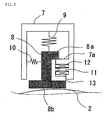
- Fig. 2 is a structural view illustrating the rope-guard braking means 6 according to Embodiment 1 of the present invention.
- a spring 10, which is fixed between the housing 7 and the rope guard 8, is set for forcing in the direction to release the engagement between the engaging portion 7a provided on the housing 7 and the engaging portion 8a of the rope guard 8.
- an actuator 11, which is fixed to the housing 7, is set for moving in the direction to engage the engaging portion 7a provided on the housing 7 and the engaging portion 8a of the rope guard 8, when it is determined to be abnormal.
- the actuator 11 adopts an electromagnet structure constituted by the housing 7 also having a stator portion, and by a coil 12 and a movable element 13; that is, the actuator 11 is configured so that, because a magnetic circuit is configured by the housing 7 and the movable element 13 due to the magnetic force generated by current flowing through the coil 12 during the current flowing through the coil 12, attraction force acts, on the movable element 13 fixed to the rope guard 8, in the direction of engaging the engaging portion 7a provided on the housing 7 and the engaging portion 8a of the rope guard 8. Because the control means 14 and the coil 12 are electrically connected to each other, the control means 14 becomes possible to control the coil 12.
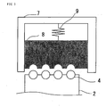
- Fig. 3 is a cross-sectional view viewed from the side of Fig. 2.
- the slide face of the rope guard 8 is formed so as to slide the sheave 2 and the rope 4 applied to the deviation sheave 5 along their surfaces.
- a plurality of rope guards 8 is generally fixed to the sheave 2 and the deviation sheave 5
- a plurality of rope-guard braking means 6 is also fixed. Therefore, without increasing the number of parts, the braking force needed per unit rope-guard braking means 6 can be decreased; consequently, the problem of the space increase can be resolved.
- the elevator hoist apparatus includes the hoist 1; the sheave 2 fixed to the output axis of the hoist 1; the speed detector 3 for detecting the output-axis rotation speed of the hoist 1; the rope-guard braking means 6 that functions as a rope guard of the sheave 2 or a deviation sheave 5 in the normal operation, and functions as a breaking means in an emergency; and the control means 14 for detecting abnormality, due to the over speed, from the rotation speed detected by the speed detector 3, and for operating the rope-guard braking means 6; therefore, a problem can be resolved, in which the acceleration for stopping the car increases when the braking characteristics of the brake decrease or malfunction occurs that the brake itself does not effectively drive, and the increase of the installing space and the increase of the number of parts can also be prevented.
- the elevator hoist apparatus is also applicable to an abnormal state such as the blackout.
- the actuator 11 of the rope-guard braking means 6 has been explained to be configured of the electromagnet composed of the coil 12, the stator, and the movable element 13; however, when significant force is needed for the maintenance, for example, by controlling the position of the movable element 13 using a motor and a reduction gear, the function can also be substituted.
- the actuator including the electromagnet an oil-pressure cylinder or an air-pressure cylinder may also substitute the function, and thus, due to the configuration using a pump, etc.
- the rope guard 8 may be configured to be slidable with respect to the sheave 2 and the deviation sheave 5.
- Fig. 4 is a structural view illustrating the rope-guard braking means 6 according to Embodiment 2 of the present invention.
- elements other than the elements specifically illustrated are the same as those in Embodiment 1, and the same symbols in Fig. 4 as those in Fig. 2 represent the same elements or the equivalent elements.
- Embodiment 1 a case has been explained in which the slide face, facing the sheave 2 or the deviation sheave 5, of the rope guard 8 included in the rope-guard braking means 6 is plane; however, in Embodiment 2, the slide face of the rope guard 8 is configured so as to be along the slide-face shape of the sheave 2 or the deviation sheave 5.
- the slide face of the rope guard 8 is configured so as to be along the slide face of the sheave 2 or the deviation sheave 5, the area of the actual slide face increases; however, in order that the rope 4 is configured not to be removed from the sheave 2 and the deviation sheave 5, because the slide face of the rope guard 8 cannot be narrowed, the force contacting the sheave 2 or the deviation sheave 5 is decreased, and consequently, the rope-guard braking means 6 can be further miniaturized.
- Embodiment 1 an effect similar to that in Embodiment 1 can be obtained. Moreover, because the slide face of the rope guard 8 is configured so as to be along the slide face of the sheave 2 or the deviation sheave 5, the force contacting the sheave 2 or the deviation sheave 5 can be decreased; therefore, the rope-guard braking means 6 can be further miniaturized.
- the elevator hoist apparatus according to the present invention is suitable for operating elevators.
Landscapes
- Engineering & Computer Science (AREA)
- Mechanical Engineering (AREA)
- Cage And Drive Apparatuses For Elevators (AREA)
- Maintenance And Inspection Apparatuses For Elevators (AREA)
Abstract
Description
- The present invention relates to elevator hoist apparatuses for moving a car up and down by driving a sheave around which a main rope engaged to the car is wound.
- In a conventional elevator hoist apparatus, a sheave is mounted to which a main rope suspending the car of the elevator is engaged. Moreover, a brake is mounted not only for holding the car in the stopped state, but also for braking the car at an emergency stop; thereby, a rotator connected to the sheave is braked to which the main rope is engaged. In this brake for holding the car in the stopped state, braking force that can stop moving the car up and down is required in accordance with a live load having any margin in response to the riding capacity of the car. Furthermore, as the brake for braking the car at the emergency stop, the braking force is limited so that the up-and-down movement of the car is decelerated based on a deceleration speed that does not physically affect a passenger inside the car.
- In the elevator hoist apparatus configured as described above, the opposite conditions of the braking ability for holding the car in the stopped state and the braking ability for emergently braking the car at the emergency stop are required to be satisfied. Therefore, because the control and maintenance of the braking torque are needed to be accurately performed, expense increases. Moreover, when, in addition to securing the desirable braking ability for holding, lightening of the car and miniaturizing of the hoist motor are accomplished, because its inertial load decreases, the deceleration speed of the car increases at the emergency stop. Therefore, a problem has occurred that the lightening and the miniaturizing of the hoist become difficult.
- In order to take measures against such problem, a technology is disclosed in
Japanese Laid-Open Patent Publication 294,385/2001 - [Patent Document 1]
Japanese Laid-Open Patent Publication 294,385/2001 - The conventional apparatus has a mechanism in which, if the car turns in an over-speed state, the brake provided in the driver operates so as to decelerate the speed of the car. The brake provided in the driver is also used at a time when the car is stopped in the normal operation. For example, due to unfavorable conditions being overlapped, when the braking characteristics of the brake decrease or malfunction occurs that the brake itself does not effectively drive, an emergency-stop device provided in the car or on the balance weight operates, and emergently stops the car; therefore, a problem occurs that the stopping acceleration inside the car increases.
- By using the technology disclosed in Patent Document 1, the above problem can be resolved; however, because the sheave, the slow brake, and the holding brake are newly provided, a problem has occurred that a space for installing them and the number of parts increase.
- An objective of the present invention, which is made to solve the above described problem, is to provide an elevator hoist apparatus that can resolve the problem in which the acceleration for stopping the car increases when the braking characteristics of the brake decrease or malfunction occurs that the brake itself does not effectively drive, and can also prevent the increase of the installing space and the increase of the number of parts.
- The present invention is characterized in that an elevator hoist apparatus includes a hoist; a sheave fixed to the output axis of the hoist; a speed detector for detecting the output-axis rotation speed of the hoist; a rope-guard braking means that functions as a rope guard of the sheave or a deviation sheave in the normal operation, and functions as a breaking means in an emergency; and a control means for detecting abnormality, due to over speed, from the rotation speed detected by the speed detector, and for operating the rope-guard braking means.
- According to such elevator emergency stop device, the hoist; the sheave fixed to the output axis of the hoist; the speed detector for detecting the output-axis rotation speed of the hoist; the rope-guard braking means that functions as the rope guard of the sheave or the deviation sheave in the normal operation, and functions as the breaking means in the emergency; and the control means for detecting abnormality, due to the over speed, from the rotation speed detected by the speed detector, and for operating the rope-guard braking means are provided; therefore, the problem can be resolved, in which the acceleration for stopping the car increases when the braking characteristics of the brake decrease or malfunction occurs that the brake itself does not effectively drive, and the increase of the installing space and the increase of the number of parts can also be prevented.
-
- Fig. 1 is a view illustrating an elevator hoist apparatus according to Embodiment 1 of the present invention;
- Fig. 2 is a structural view illustrating a rope-guard braking means 6 according to Embodiment 1 of the present invention;
- Fig. 3 is a cross-sectional view viewed from the side of Fig. 2; and
- Fig. 4 is a structural view illustrating the rope-guard braking means 6 according to
Embodiment 2 of the present invention. -
- 1: Hoist
- 2: Sheave
- 3: Speed detector
- 4: Rope
- 5: Deviation sheave
- 6: Rope-guard breaking means
- 7: Housing
- 7a: Engaging portion
- 8: Rope guard
- 8a: Engaging portion
- 8b: Slide face
- 9: Spring
- 10: Spring
- 11: Actuator
- 12: Coil
- 13: Movable element
- 14: Control means
- As the best mode for carrying out the present invention,
Embodiments 1 and 2 are explained. - Fig. 1 is a view illustrating an elevator hoist apparatus according to Embodiment 1 of the present invention. A
sheave 2 is fixed to the leading axis of a hoist 1 on a table to which the hoist apparatus is mounted, and a speed detector 3 is coaxially fixed to the output axis of the hoist 1 in order to detect a rotation speed of thesheave 2 rotating due to driving of the hoist 1.
Moreover, arope 4 for moving a car up and down through the up-and-down path is applied to thesheave 2. Thus, therope 4 is applied to adeviation sheave 5 rotatably fixed to the table to which the hoist apparatus is mounted, so that therope 4 suspends the car from a predetermined position. Furthermore, although not illustrated here, a brake for braking the drive axis of the hoist 1 during the normal operation is installed inside the hoist. - Generally, in the elevator hoist apparatus, a rope guard is provided along the periphery of the
sheave 2 and thedeviation sheave 5 so that therope 4 is not removed from thesheave 2 and thedeviation sheave 5 during the operation. On the other hand, in the elevator hoist apparatus, from the viewpoint of safety, preparing for a case in which the brake provided inside the hoist 1 used during an operation loses its function to be originally effective, a spare brake other than that is needed to be arranged. Because the opposite conditions of the braking ability for holding the car during the stopped state and the braking ability for emergently braking the car at the emergency stop are required to be satisfied, in the embodiment disclosed inJapanese Laid-Open Patent Publication 294,385/2001 - Therefore, as in Fig. 1, a rope-guard braking means 6 is placed, instead of the rope guard, at the position that the rope guard is to be provided. Moreover, a control means 14 for controlling the operation of the rope-guard braking means 6 is electrically connected, and thus, the control means 14 is also electrically connected to the speed detector 3. A structure of the rope-guard braking means 6 is explained. Fig. 2 is a structural view illustrating the rope-guard braking means 6 according to Embodiment 1 of the present invention.
- Due to the force of a
spring 9 whose one end is fixed to ahousing 7, and whose the other end is fixed to arope guard 8 having a slide face facing thesheave 2 or thedeviation sheave 5, by contacting the slide face of therope guard 8 with that of thesheave 2 or thedeviation sheave 5, braking force can be obtained. In order that therope guard 8 only functions as a guard for therope 4, by engaging an engagingportion 7a provided on thehousing 7 and an engaging portion 8a of therope guard 8, the slide face of therope guard 8 and that of thesheave 2 or thedeviation sheave 5 are configured not to contact to each other. Moreover, aspring 10, which is fixed between thehousing 7 and therope guard 8, is set for forcing in the direction to release the engagement between the engagingportion 7a provided on thehousing 7 and the engaging portion 8a of therope guard 8. Furthermore, anactuator 11, which is fixed to thehousing 7, is set for moving in the direction to engage the engagingportion 7a provided on thehousing 7 and the engaging portion 8a of therope guard 8, when it is determined to be abnormal. - In Fig. 2, the
actuator 11 adopts an electromagnet structure constituted by thehousing 7 also having a stator portion, and by acoil 12 and amovable element 13; that is, theactuator 11 is configured so that, because a magnetic circuit is configured by thehousing 7 and themovable element 13 due to the magnetic force generated by current flowing through thecoil 12 during the current flowing through thecoil 12, attraction force acts, on themovable element 13 fixed to therope guard 8, in the direction of engaging the engagingportion 7a provided on thehousing 7 and the engaging portion 8a of therope guard 8. Because the control means 14 and thecoil 12 are electrically connected to each other, the control means 14 becomes possible to control thecoil 12. - Fig. 3 is a cross-sectional view viewed from the side of Fig. 2. The slide face of the
rope guard 8 is formed so as to slide thesheave 2 and therope 4 applied to thedeviation sheave 5 along their surfaces. - An operation is explained.
When the control means 14 detects an over speed of the car due to the output value of the speed detector 3, coaxially fixed to the output axis of the hoist 1, for detecting the rotation speed of the leading axis, the control means 14 shuts down the current flowing across thecoil 12 in the normal operation state. Thereby, the force acts in the direction to release the engagement between the engagingportion 7a provided on thehousing 7 and the engaging portion 8a of therope guard 8, and the engagement is removed.
Then, therope guard 8 moves in the direction of thesheave 2 or thedeviation sheave 5 by the force of thespring 9, and the slide faces slide against each other. Thesheave 2 and thedeviation sheave 5 can be braked by the slide. - Because a plurality of
rope guards 8 is generally fixed to thesheave 2 and thedeviation sheave 5, a plurality of rope-guard braking means 6 is also fixed. Therefore, without increasing the number of parts, the braking force needed per unit rope-guard braking means 6 can be decreased; consequently, the problem of the space increase can be resolved. - Moreover, by providing a plurality of rope-guard braking means 6, a function as an emergency brake is executed; therefore, a problem, in which the acceleration for stopping the car increases when the braking characteristics of the brake decrease or malfunction occurs that the brake itself does not effectively drive, can be resolved due to a function corresponding to the slow brake represented in
Japanese Laid-Open Patent Publication 294,385/2001 - Therefore, according to Embodiment 1, the elevator hoist apparatus includes the hoist 1; the
sheave 2 fixed to the output axis of the hoist 1; the speed detector 3 for detecting the output-axis rotation speed of the hoist 1; the rope-guard braking means 6 that functions as a rope guard of thesheave 2 or adeviation sheave 5 in the normal operation, and functions as a breaking means in an emergency; and the control means 14 for detecting abnormality, due to the over speed, from the rotation speed detected by the speed detector 3, and for operating the rope-guard braking means 6; therefore, a problem can be resolved, in which the acceleration for stopping the car increases when the braking characteristics of the brake decrease or malfunction occurs that the brake itself does not effectively drive, and the increase of the installing space and the increase of the number of parts can also be prevented. - Moreover, in this embodiment, although a case is explained in which the control means 14 operates normally, if electric power becomes impossible to be supplied to the control means 14 due to the blackout, etc., the control means 14 cannot be controlled; however, because the electric power is not supplied, current does not flow across the
coil 12 as a component of theactuator 11 included in the rope-guard braking means 6 electrically connected to the control means 14, and consequently, the braking operation is performed against the movement of the car. Therefore, the elevator hoist apparatus according to this embodiment is also applicable to an abnormal state such as the blackout. - Here, in Embodiment 1, the
actuator 11 of the rope-guard braking means 6 has been explained to be configured of the electromagnet composed of thecoil 12, the stator, and themovable element 13; however, when significant force is needed for the maintenance, for example, by controlling the position of themovable element 13 using a motor and a reduction gear, the function can also be substituted. Needless to say, instead of the actuator including the electromagnet, an oil-pressure cylinder or an air-pressure cylinder may also substitute the function, and thus, due to the configuration using a pump, etc. utilizing an electric device such as a motor for supplying the air pressure and the oil pressure, when electric power is shut down, the cylinder does not function; therefore, therope guard 8 may be configured to be slidable with respect to thesheave 2 and thedeviation sheave 5. - Fig. 4 is a structural view illustrating the rope-guard braking means 6 according to
Embodiment 2 of the present invention. Here, elements other than the elements specifically illustrated are the same as those in Embodiment 1, and the same symbols in Fig. 4 as those in Fig. 2 represent the same elements or the equivalent elements. - The difference from Embodiment 1 is explained. In Embodiment 1, a case has been explained in which the slide face, facing the
sheave 2 or thedeviation sheave 5, of therope guard 8 included in the rope-guard braking means 6 is plane; however, inEmbodiment 2, the slide face of therope guard 8 is configured so as to be along the slide-face shape of thesheave 2 or thedeviation sheave 5. - Therefore, because the slide face of the
rope guard 8 is configured so as to be along the slide face of thesheave 2 or thedeviation sheave 5, the area of the actual slide face increases; however, in order that therope 4 is configured not to be removed from thesheave 2 and thedeviation sheave 5, because the slide face of therope guard 8 cannot be narrowed, the force contacting thesheave 2 or thedeviation sheave 5 is decreased, and consequently, the rope-guard braking means 6 can be further miniaturized. - Therefore, according to Embodiment 1, an effect similar to that in Embodiment 1 can be obtained. Moreover, because the slide face of the
rope guard 8 is configured so as to be along the slide face of thesheave 2 or thedeviation sheave 5, the force contacting thesheave 2 or thedeviation sheave 5 can be decreased; therefore, the rope-guard braking means 6 can be further miniaturized. - The elevator hoist apparatus according to the present invention is suitable for operating elevators.
Claims (2)
- An elevator hoist apparatus characterized in that the apparatus comprises:a hoist;a sheave fixed to the output axis of the hoist;a speed detector for detecting the output-axis rotation speed of the hoist;a rope-guard braking means for functioning as a rope guard of the sheave or a deviation sheave in the normal operation, and for functioning as a breaking means in an emergency; anda control means for detecting abnormality, due to over speed, from the rotation speed detected by the speed detector, and for operating the rope-guard braking means.
- An elevator hoist apparatus as recited in claim 1, wherein the face of the sliding portion of either the sheave or the deviation sheave of the rope-guard braking means is a circular arc shape to be along the peripheral shape of either the sheave or the deviation sheave.
Applications Claiming Priority (1)
| Application Number | Priority Date | Filing Date | Title |
|---|---|---|---|
| PCT/JP2005/007537 WO2006114872A1 (en) | 2005-04-20 | 2005-04-20 | Hoist device for elevator |
Publications (2)
| Publication Number | Publication Date |
|---|---|
| EP1873111A1 true EP1873111A1 (en) | 2008-01-02 |
| EP1873111A4 EP1873111A4 (en) | 2012-11-14 |
Family
ID=37214510
Family Applications (1)
| Application Number | Title | Priority Date | Filing Date |
|---|---|---|---|
| EP05734540A Withdrawn EP1873111A4 (en) | 2005-04-20 | 2005-04-20 | LIFTING DEVICE FOR ELEVATOR |
Country Status (4)
| Country | Link |
|---|---|
| EP (1) | EP1873111A4 (en) |
| JP (1) | JPWO2006114872A1 (en) |
| CN (1) | CN1993289B (en) |
| WO (1) | WO2006114872A1 (en) |
Cited By (1)
| Publication number | Priority date | Publication date | Assignee | Title |
|---|---|---|---|---|
| WO2014086639A1 (en) * | 2012-12-04 | 2014-06-12 | Thyssenkrupp Elevator Ag | Cable clamp, and lift system having a cable clamp |
Families Citing this family (7)
| Publication number | Priority date | Publication date | Assignee | Title |
|---|---|---|---|---|
| CN101811635B (en) * | 2009-02-20 | 2012-09-26 | 三菱电机株式会社 | Rope swing detecting device for the elevator and control method for operation automaticlly recovering after earthquake |
| CN102674118A (en) * | 2012-02-16 | 2012-09-19 | 郭自刚 | Elevator traction machine of steel wire rope antiskid device |
| CN103224175A (en) * | 2013-04-09 | 2013-07-31 | 康力电梯股份有限公司 | Brake circuit controller of traction machine |
| CN103253577B (en) * | 2013-05-22 | 2015-09-09 | 河南科技大学 | A kind of limiting brake system for hanging elevator |
| JP6395945B2 (en) * | 2015-09-16 | 2018-09-26 | 三菱電機株式会社 | Elevator Bending Car Replacement Method and Bending Car Replacement Jig |
| JP6272374B2 (en) * | 2016-03-18 | 2018-01-31 | 三菱電機ビルテクノサービス株式会社 | Rope detachment check device |
| CN114955778A (en) * | 2022-07-04 | 2022-08-30 | 浙江速捷电梯有限公司 | Emergency braking device for elevator safety |
Family Cites Families (6)
| Publication number | Priority date | Publication date | Assignee | Title |
|---|---|---|---|---|
| KR860003715Y1 (en) * | 1982-12-06 | 1986-12-30 | 미쓰비시덴기 가부시기 가이샤 | Elevator traction equipment |
| JPS59212371A (en) * | 1983-05-19 | 1984-12-01 | 株式会社東芝 | Elevator |
| JPH0631143B2 (en) * | 1986-04-04 | 1994-04-27 | 三菱電機株式会社 | Elevator safety device |
| JP2763244B2 (en) * | 1993-01-07 | 1998-06-11 | 三菱電機株式会社 | Elevator braking system |
| JP4439074B2 (en) * | 2000-03-29 | 2010-03-24 | 三菱電機株式会社 | Elevator emergency stop device |
| JP4722855B2 (en) * | 2004-09-09 | 2011-07-13 | 三菱電機株式会社 | Elevator equipment |
-
2005
- 2005-04-20 WO PCT/JP2005/007537 patent/WO2006114872A1/en not_active Ceased
- 2005-04-20 CN CN2005800266555A patent/CN1993289B/en not_active Expired - Fee Related
- 2005-04-20 JP JP2006526880A patent/JPWO2006114872A1/en active Pending
- 2005-04-20 EP EP05734540A patent/EP1873111A4/en not_active Withdrawn
Cited By (1)
| Publication number | Priority date | Publication date | Assignee | Title |
|---|---|---|---|---|
| WO2014086639A1 (en) * | 2012-12-04 | 2014-06-12 | Thyssenkrupp Elevator Ag | Cable clamp, and lift system having a cable clamp |
Also Published As
| Publication number | Publication date |
|---|---|
| CN1993289B (en) | 2012-04-18 |
| EP1873111A4 (en) | 2012-11-14 |
| JPWO2006114872A1 (en) | 2008-12-11 |
| CN1993289A (en) | 2007-07-04 |
| WO2006114872A1 (en) | 2006-11-02 |
Similar Documents
| Publication | Publication Date | Title |
|---|---|---|
| JP5247690B2 (en) | Elevator safety device | |
| EP1431230B1 (en) | Emergency brake device of elevator | |
| KR101181205B1 (en) | Elevator apparatus | |
| EP2888500B1 (en) | Brake | |
| JP2019202891A (en) | System arrangement for lift mechanism and method for operating the system arrangement | |
| WO2012017549A1 (en) | Elevator speed governor | |
| CN112088138B (en) | Elevator safety devices and elevator safety systems | |
| EP1873111A1 (en) | Hoist device for elevator | |
| WO2011004468A1 (en) | Direct-acting drum brake device for elevator | |
| EP3696129B1 (en) | Elevator monitoring arrangement and method for monitoring an elevator | |
| JP2002316777A (en) | Elevator equipment | |
| KR101941388B1 (en) | Elevator with a brake device | |
| EP1856422B1 (en) | Elevator brake actuator having a shape-changing material for brake control | |
| US5201821A (en) | Disc brake elevator drive sheave | |
| EP2090540B1 (en) | Elevator system | |
| JP2011121742A (en) | Elevator braking device | |
| JP5172695B2 (en) | Elevator equipment | |
| KR101219230B1 (en) | Elevator safety circuit device | |
| US20180251336A1 (en) | Elevator brake | |
| US7419033B2 (en) | Emergency brake device for elevator | |
| US11679958B2 (en) | Safety gear arrangement, elevator system, and method for operating a safety gear of an elevator system | |
| KR20120014003A (en) | Control device of elevator | |
| KR100904115B1 (en) | Hoist for elevator | |
| JP2011153010A (en) | Elevator device | |
| WO2026002627A1 (en) | Elevator and method for terminating a maintance trip of an elevator |
Legal Events
| Date | Code | Title | Description |
|---|---|---|---|
| PUAI | Public reference made under article 153(3) epc to a published international application that has entered the european phase |
Free format text: ORIGINAL CODE: 0009012 |
|
| 17P | Request for examination filed |
Effective date: 20070202 |
|
| AK | Designated contracting states |
Kind code of ref document: A1 Designated state(s): DE |
|
| DAX | Request for extension of the european patent (deleted) | ||
| RBV | Designated contracting states (corrected) |
Designated state(s): DE |
|
| A4 | Supplementary search report drawn up and despatched |
Effective date: 20121015 |
|
| RIC1 | Information provided on ipc code assigned before grant |
Ipc: B66B 5/18 20060101ALI20121009BHEP Ipc: B66D 5/08 20060101ALI20121009BHEP Ipc: B66D 5/30 20060101ALI20121009BHEP Ipc: B66B 11/08 20060101AFI20121009BHEP Ipc: B66D 5/16 20060101ALI20121009BHEP Ipc: B66B 5/06 20060101ALI20121009BHEP |
|
| STAA | Information on the status of an ep patent application or granted ep patent |
Free format text: STATUS: THE APPLICATION IS DEEMED TO BE WITHDRAWN |
|
| 18D | Application deemed to be withdrawn |
Effective date: 20130115 |