EP1873109A1 - Heat diffusion device for elevator hoistway - Google Patents
Heat diffusion device for elevator hoistway Download PDFInfo
- Publication number
- EP1873109A1 EP1873109A1 EP05730672A EP05730672A EP1873109A1 EP 1873109 A1 EP1873109 A1 EP 1873109A1 EP 05730672 A EP05730672 A EP 05730672A EP 05730672 A EP05730672 A EP 05730672A EP 1873109 A1 EP1873109 A1 EP 1873109A1
- Authority
- EP
- European Patent Office
- Prior art keywords
- shaft
- air
- blower
- car
- thermal diffusion
- Prior art date
- Legal status (The legal status is an assumption and is not a legal conclusion. Google has not performed a legal analysis and makes no representation as to the accuracy of the status listed.)
- Withdrawn
Links
Images




Classifications
-
- B—PERFORMING OPERATIONS; TRANSPORTING
- B66—HOISTING; LIFTING; HAULING
- B66B—ELEVATORS; ESCALATORS OR MOVING WALKWAYS
- B66B11/00—Main component parts of lifts in, or associated with, buildings or other structures
- B66B11/0005—Constructional features of hoistways
-
- Y—GENERAL TAGGING OF NEW TECHNOLOGICAL DEVELOPMENTS; GENERAL TAGGING OF CROSS-SECTIONAL TECHNOLOGIES SPANNING OVER SEVERAL SECTIONS OF THE IPC; TECHNICAL SUBJECTS COVERED BY FORMER USPC CROSS-REFERENCE ART COLLECTIONS [XRACs] AND DIGESTS
- Y02—TECHNOLOGIES OR APPLICATIONS FOR MITIGATION OR ADAPTATION AGAINST CLIMATE CHANGE
- Y02B—CLIMATE CHANGE MITIGATION TECHNOLOGIES RELATED TO BUILDINGS, e.g. HOUSING, HOUSE APPLIANCES OR RELATED END-USER APPLICATIONS
- Y02B50/00—Energy efficient technologies in elevators, escalators and moving walkways, e.g. energy saving or recuperation technologies
Definitions
- the present invention relates to a thermal diffusion system for a shaft of a machine room-less elevator, in which a drive unit and a control unit are provided in an upper part of the shaft. More particularly, it relates to the prevention of the rise in temperature in the vicinity of the control unit and the drive unit and the ventilation in the upper part of the shaft.
- an air conditioner for elevator which is provided with a cooling unit for supplying cold air, is configured so that the cooling unit is provided in a machine room in an upper part of a shaft, a duct for guiding cold air blown out of the cooling unit is provided between the machine room and the interior of the shaft, and a ventilating fan, which sucks air in the shaft from upside and blows it off downward, is provided at a predetermined height position in the shaft.
- a ventilating fan which sucks air in the shaft from upside and blows it off downward, is provided at a predetermined height position in the shaft.
- Patent Document 1 Japanese Patent Laid-Open No. 5-193863
- the conventional air conditioner for elevator as described above has a problem in that a cooling unit is needed and the equipment is complicated, and also the electric power consumption is high, so that the installation costs and running costs are high.
- the present invention has been made to solve the above problem, and accordingly an object thereof is to provide a thermal diffusion system for an elevator shaft, in which the equipment is simple and the electric power consumption is low, so that the installation costs and running costs are low.
- the present invention provides a thermal diffusion system for an elevator shaft, characterized in that in a machine room-less elevator having a shaft; a car and a counter weight which are connected to each other via a rope disposed in the shaft and run in the shaft in the direction opposite to each other; a drive unit for driving the car and the counter weight, which is provided in an upper part of the shaft and around which the rope is set; and a control unit for controlling the drive unit, which is provided in an upper part of the shaft, the thermal diffusion system includes a blower provided in an upper part of the shaft; an air intake duct whose air inlet at one end is arranged near the control unit or the drive unit and the other end of which is attached to the intake side of the blower; and an exhaust air duct one end of which is attached to the exhaust side of the blower and whose air outlet on the other end is arranged so that air is exhausted downward in the shaft.
- the air outlet of the exhaust air duct is arranged at a position lower than the ceiling of the car stopping on the highest floor.
- the length of the exhaust air duct is extended so that the air outlet is arranged at a position lower than the ceiling of the car stopping on the highest stop floor in the elevation range in which the car is usually often used.
- the blower is arranged in a corner portion in an upper part of the shaft.
- the blower is arranged at a position overlapping with the car in plan view and above the car.
- the air intake duct is branched into a fork shape and has two air inlets, and one air inlet is arranged near the control unit and the other air inlet is arranged near the drive unit.
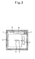
- FIGS 1 and 2 are a longitudinal sectional view and a plan view, respectively, showing a thermal diffusion system for an elevator shaft in accordance with embodiment 1 of the present invention.
- An elevator system of this invention which is what is called a machine room-less elevator, includes a car 2 of the elevator, which runs along a guide rail in a shaft 1; a counter weight 3 that runs along another guide rail in the shaft in the direction opposite to the car 1; a drive unit 4 disposed in an upper part of the shaft 1; a rope 5 set around the drive unit 4 so as to connect with the car 2 and the counter weight 3 at both ends; and a control unit 6 that is disposed on one-side wall in an upper part of the shaft 1 to control the drive unit 4.
- the drive unit 4 and the control unit 6, which are easily heated by dissipated heat, are disposed in the upper part of the shaft 1.
- a blower 7, whose rotation axis is disposed vertically is provided in a corner portion in an upper part of the shaft 1.
- This blower 1 includes an air intake duct 8, whose air inlet at one end is arranged near a portion above the control unit 6 and the other end of which is attached to the intake side of the blower 7, and an exhaust air duct 9, one end of which is attached to the exhaust side of the blower 7 and whose air outlet at the other end is arranged so that air is exhausted downward in the shaft 1.
- an extension duct 12 is connected as necessary to the air outlet at the other end of the exhaust air duct 9.
- the extension duct 12 is connected to the other end of the exhaust air duct 9, by which the air outlet is arranged at a position lower than the ceiling of the car 2 stopping on the highest stop floor in the elevation range in which the car 2 is usually often used.
- the air outlet is arranged at a position lower than the ceiling of the car 2 stopping on the highest stop floor in the elevation range in which the car 2 is usually often used.
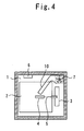
- Figures 3 and 4 are a longitudinal sectional view and a plan view, respectively, showing a thermal diffusion system for an elevator shaft in accordance with embodiment 2 of the present invention.
- the air inlet at one end of the air intake duct 8 attached to the intake side of the blower 1 is arranged near a portion above the control unit 6.
- an air inlet at one end of an air intake duct 10 attached to the intake side of the blower 7 is arranged near the drive unit 4.
- Other configurations are the same as those of embodiment 1.
- Figures 5 and 6 are a longitudinal sectional view and a plan view, respectively, showing a thermal diffusion system for an elevator shaft in accordance with embodiment 3 of the present invention.
- the blower 7, whose rotation axis is disposed vertically is provided in a corner portion in an upper part of the shaft 1.
- a blower 13, whose rotation axis is disposed horizontally is arranged at a position overlapping with the car 2 in plan view and above the car 2.
- Other configurations are almost the same as those of embodiment 1.
- a maintenance worker can gain access to the blower 13 from the top of the car 2, so that he/she can perform maintenance work of the blower easily on the top of the car.
- Figures 7 and 8 are a longitudinal sectional view and a plan view, respectively, showing a thermal diffusion system for an elevator shaft in accordance with embodiment 4 of the present invention.
- the air inlet at one end of the air intake duct 8 attached to the intake side of the blower 1 is arranged near a portion above the control unit 6, and in embodiment 2, the air inlet at one end of the air intake duct 10 attached to the intake side of the blower 7 is arranged near the drive unit 4.
- a branch-type air intake duct 11 which is attached to the intake side of the blower 7 and is branched into a fork shape is provided so that one air inlet of this branch-type air intake duct 11 is arranged near the control unit 6 and the other air inlet thereof is arranged near the drive unit 4.
- Other configurations are almost the same as those of embodiment 1.
- the thermal diffusion system for an elevator shaft in accordance with the present invention can be configured so that, in a machine room-less elevator in which a drive unit and a control unit are provided in an upper part of the shaft, heat dissipated from the control unit and the drive unit is absorbed efficiently, thereby preventing the rise in temperature in the vicinity of these pieces of equipment, and the heat in an upper part of the shaft can be allowed to escape downward and can be diffused.
Landscapes
- Engineering & Computer Science (AREA)
- Civil Engineering (AREA)
- Mechanical Engineering (AREA)
- Structural Engineering (AREA)
- Lift-Guide Devices, And Elevator Ropes And Cables (AREA)
- Cage And Drive Apparatuses For Elevators (AREA)
Abstract
Description
- The present invention relates to a thermal diffusion system for a shaft of a machine room-less elevator, in which a drive unit and a control unit are provided in an upper part of the shaft. More particularly, it relates to the prevention of the rise in temperature in the vicinity of the control unit and the drive unit and the ventilation in the upper part of the shaft.
- Conventionally, an air conditioner for elevator, which is provided with a cooling unit for supplying cold air, is configured so that the cooling unit is provided in a machine room in an upper part of a shaft, a duct for guiding cold air blown out of the cooling unit is provided between the machine room and the interior of the shaft, and a ventilating fan, which sucks air in the shaft from upside and blows it off downward, is provided at a predetermined height position in the shaft. By the cooling unit provided in the machine room, air is taken in from the interior of the shaft via an air intake duct, and cold air is blown off vertically downward in the shaft via an air outlet of a blowoff duct, and falls in the shaft. The air containing this cold air is sucked by the ventilating fan from the upside via an air inlet at the predetermined height position in the shaft, and blown off further downward via an air outlet to cool the interior of the shaft (for example, refer to Patent Document 1).
- [Patent Document 1]:
Japanese Patent Laid-Open No. 5-193863 - However, the conventional air conditioner for elevator as described above has a problem in that a cooling unit is needed and the equipment is complicated, and also the electric power consumption is high, so that the installation costs and running costs are high.
- The present invention has been made to solve the above problem, and accordingly an object thereof is to provide a thermal diffusion system for an elevator shaft, in which the equipment is simple and the electric power consumption is low, so that the installation costs and running costs are low.
- The present invention provides a thermal diffusion system for an elevator shaft, characterized in that in a machine room-less elevator having a shaft; a car and a counter weight which are connected to each other via a rope disposed in the shaft and run in the shaft in the direction opposite to each other; a drive unit for driving the car and the counter weight, which is provided in an upper part of the shaft and around which the rope is set; and a control unit for controlling the drive unit, which is provided in an upper part of the shaft, the thermal diffusion system includes a blower provided in an upper part of the shaft; an air intake duct whose air inlet at one end is arranged near the control unit or the drive unit and the other end of which is attached to the intake side of the blower; and an exhaust air duct one end of which is attached to the exhaust side of the blower and whose air outlet on the other end is arranged so that air is exhausted downward in the shaft.
- Also, the air outlet of the exhaust air duct is arranged at a position lower than the ceiling of the car stopping on the highest floor.
- Also, the length of the exhaust air duct is extended so that the air outlet is arranged at a position lower than the ceiling of the car stopping on the highest stop floor in the elevation range in which the car is usually often used.
- Also, the blower is arranged in a corner portion in an upper part of the shaft.
- Also, the blower is arranged at a position overlapping with the car in plan view and above the car.
- Further, the air intake duct is branched into a fork shape and has two air inlets, and one air inlet is arranged near the control unit and the other air inlet is arranged near the drive unit.
- According to the present invention, there is offered an advantage that heat dissipated from the control unit and the drive unit is absorbed efficiently, thereby preventing the rise in temperature in the vicinity of these pieces of equipment, and the heat in an upper part of the shaft is allowed to escape downward and is diffused.
-
- Figure 1 is a longitudinal sectional view of a thermal diffusion system for an elevator shaft in accordance with
embodiment 1 of the present invention; - Figure 2 is a plan view of a thermal diffusion system for an elevator shaft in accordance with
embodiment 1 of the present invention; - Figure 3 is a longitudinal sectional view of a thermal diffusion system for an elevator shaft in accordance with
embodiment 2 of the present invention; - Figure 4 is a plan view of a thermal diffusion system for an elevator shaft in accordance with
embodiment 2 of the present invention; - Figure 5 is a longitudinal sectional view of a thermal diffusion system for an elevator shaft in accordance with
embodiment 3 of the present invention; - Figure 6 is a plan view of a thermal diffusion system for an elevator shaft in accordance with
embodiment 3 of the present invention; - Figure 7 is a longitudinal sectional view of a thermal diffusion system for an elevator shaft in accordance with
embodiment 4 of the present invention; and - Figure 8 is a plan view of a thermal diffusion system for an elevator shaft in accordance with
embodiment 4 of the present invention. -
- 1
- shaft
- 2
- car
- 3
- counter weight
- 4
- drive unit
- 5
- rope
- 6
- control unit
- 7
- blower
- 8
- air intake duct
- 9
- exhaust air duct
- 10
- air intake duct
- 11
- branch-type air intake duct
- 12
- extension duct
- 13
- blower
- The present invention will now be described in more detail with reference to the accompanying drawings.
- Figures 1 and 2 are a longitudinal sectional view and a plan view, respectively, showing a thermal diffusion system for an elevator shaft in accordance with
embodiment 1 of the present invention. An elevator system of this invention, which is what is called a machine room-less elevator, includes acar 2 of the elevator, which runs along a guide rail in ashaft 1; acounter weight 3 that runs along another guide rail in the shaft in the direction opposite to thecar 1; adrive unit 4 disposed in an upper part of theshaft 1; arope 5 set around thedrive unit 4 so as to connect with thecar 2 and thecounter weight 3 at both ends; and acontrol unit 6 that is disposed on one-side wall in an upper part of theshaft 1 to control thedrive unit 4. That is to say, thedrive unit 4 and thecontrol unit 6, which are easily heated by dissipated heat, are disposed in the upper part of theshaft 1.
In a corner portion in an upper part of theshaft 1, ablower 7, whose rotation axis is disposed vertically, is provided. Thisblower 1 includes anair intake duct 8, whose air inlet at one end is arranged near a portion above thecontrol unit 6 and the other end of which is attached to the intake side of theblower 7, and anexhaust air duct 9, one end of which is attached to the exhaust side of theblower 7 and whose air outlet at the other end is arranged so that air is exhausted downward in theshaft 1. Also, to the air outlet at the other end of theexhaust air duct 9, anextension duct 12 is connected as necessary. - In the thermal diffusion system for an elevator shaft configured as described above, heat dissipated from the
control unit 6 is sucked through the air inlet at one end of theair intake duct 8 by the blowing action of theblower 7, being sent to theexhaust air duct 9, and is discharged to a portion below the uppermost stop position of thecar 2 in theshaft 1. Therefore, air is stirred by the downward operation of thecar 2, by which heat is diffused to a lower part of theshaft 1. Further, the length of theexhaust air duct 9 is extended so that the air outlet is arranged at a position lower than the ceiling of thecar 2 stopping on the highest floor, by which air is sent to under thecar 2. Therefore, a large amount of air is further pushed down to a lower part of the shaft by the downward operation of thecar 2, so that heat is efficiently diffused to a lower part of the shaft.
Also, in the case where thecar 2 stops less frequently on the highest floor, theextension duct 12 is connected to the other end of theexhaust air duct 9, by which the air outlet is arranged at a position lower than the ceiling of thecar 2 stopping on the highest stop floor in the elevation range in which thecar 2 is usually often used. Thereby, air is sent to under thecar 2. Therefore, a large amount of air is further pushed down to a lower part of the shaft by the downward operation of thecar 2, so that heat is diffused efficiently to a lower part of the shaft.
In an upper part of theshaft 1, a temperature sensor (not shown) is provided so that when the temperature increases to a preset value, theblower 7 is operated. - According to the above-described configuration, there is offered an advantage that heat dissipated from the control unit and the drive unit is absorbed efficiently, thereby preventing the rise in temperature in the vicinity of these pieces of equipment, and the heat in an upper part of the shaft is allowed to escape downward and is diffused.
- Figures 3 and 4 are a longitudinal sectional view and a plan view, respectively, showing a thermal diffusion system for an elevator shaft in accordance with
embodiment 2 of the present invention.
In the above-describedembodiment 1, the air inlet at one end of theair intake duct 8 attached to the intake side of theblower 1 is arranged near a portion above thecontrol unit 6. By contrast, inembodiment 2, an air inlet at one end of anair intake duct 10 attached to the intake side of theblower 7 is arranged near thedrive unit 4. Other configurations are the same as those ofembodiment 1. - In the thermal diffusion system for an elevator shaft configured as described above, heat dissipated from the
drive unit 4 is sucked through the air inlet at one end of theair intake duct 10 by the blowing action of theblower 7, being sent to theexhaust air duct 9, and is discharged to a portion below the uppermost stop position of thecar 2 in theshaft 1. Therefore, air is stirred by the downward operation of thecar 2, by which heat is diffused to a lower part of theshaft 1. - Figures 5 and 6 are a longitudinal sectional view and a plan view, respectively, showing a thermal diffusion system for an elevator shaft in accordance with
embodiment 3 of the present invention.
In the above-describedembodiment 1, theblower 7, whose rotation axis is disposed vertically, is provided in a corner portion in an upper part of theshaft 1. By contrast, inembodiment 3, ablower 13, whose rotation axis is disposed horizontally, is arranged at a position overlapping with thecar 2 in plan view and above thecar 2. Other configurations are almost the same as those ofembodiment 1. - In the thermal diffusion system for an elevator shaft configured as described above, a maintenance worker can gain access to the
blower 13 from the top of thecar 2, so that he/she can perform maintenance work of the blower easily on the top of the car. - Figures 7 and 8 are a longitudinal sectional view and a plan view, respectively, showing a thermal diffusion system for an elevator shaft in accordance with
embodiment 4 of the present invention.
In the above-describedembodiment 1, the air inlet at one end of theair intake duct 8 attached to the intake side of theblower 1 is arranged near a portion above thecontrol unit 6, and inembodiment 2, the air inlet at one end of theair intake duct 10 attached to the intake side of theblower 7 is arranged near thedrive unit 4. By contrast, inembodiment 4, a branch-typeair intake duct 11 which is attached to the intake side of theblower 7 and is branched into a fork shape is provided so that one air inlet of this branch-typeair intake duct 11 is arranged near thecontrol unit 6 and the other air inlet thereof is arranged near thedrive unit 4. Other configurations are almost the same as those ofembodiment 1. - In the thermal diffusion system for an elevator shaft configured as described above, heat dissipated from the
control unit 6 and thedrive unit 4 is sucked through the two branched air inlets of the branch-typeair intake duct 11 by the blowing action of theblower 7, being sent to theexhaust air duct 9, and is discharged to a portion below the uppermost stop position of thecar 2 in theshaft 1. Therefore, air is stirred by the downward operation of thecar 2, by which heat is diffused to a lower part of theshaft 1. Industrial Applicability - As described above, the thermal diffusion system for an elevator shaft in accordance with the present invention can be configured so that, in a machine room-less elevator in which a drive unit and a control unit are provided in an upper part of the shaft, heat dissipated from the control unit and the drive unit is absorbed efficiently, thereby preventing the rise in temperature in the vicinity of these pieces of equipment, and the heat in an upper part of the shaft can be allowed to escape downward and can be diffused.
Claims (6)
- A thermal diffusion system for an elevator shaft, characterized in that
in a machine room-less elevator having a shaft; a car and a counter weight which are connected to each other via a rope disposed in the shaft and run in the shaft in the direction opposite to each other; a drive unit for driving the car and the counter weight, which is provided in an upper part of the shaft and around which the rope is set; and a control unit for controlling the drive unit, which is provided in an upper part of the shaft, the thermal diffusion system comprises:a blower provided in an upper part of the shaft;an air intake duct whose air inlet at one end is arranged near the control unit or the drive unit and the other end of which is attached to the intake side of the blower; andan exhaust air duct one end of which is attached to the exhaust side of the blower and whose air outlet on the other end is arranged so that air is exhausted downward in the shaft. - The thermal diffusion system for an elevator shaft according to claim 1, characterized in that the air outlet of the exhaust air duct is arranged at a position lower than the ceiling of the car stopping on the highest floor.
- The thermal diffusion system for an elevator shaft according to claim 1, characterized in that the length of the exhaust air duct is extended so that the air outlet is arranged at a position lower than the ceiling of the car stopping on the highest stop floor in the elevation range in which the car is usually often used.
- The thermal diffusion system for an elevator shaft according to any one of claims 1 to 3, characterized in that the blower is arranged in a corner portion in an upper part of the shaft.
- The thermal diffusion system for an elevator shaft according to any one of claims 1 to 3, characterized in that the blower is arranged at a position overlapping with the car in plan view and above the car.
- The thermal diffusion system for an elevator shaft according to any one of claims 1 to 5, characterized in that the air intake duct is branched into a fork shape and has two air inlets, and one air inlet is arranged near the control unit and the other air inlet is arranged near the drive unit.
Applications Claiming Priority (1)
| Application Number | Priority Date | Filing Date | Title |
|---|---|---|---|
| PCT/JP2005/007401 WO2006114856A1 (en) | 2005-04-18 | 2005-04-18 | Heat diffusion device for elevator hoistway |
Publications (2)
| Publication Number | Publication Date |
|---|---|
| EP1873109A1 true EP1873109A1 (en) | 2008-01-02 |
| EP1873109A4 EP1873109A4 (en) | 2012-10-10 |
Family
ID=37214494
Family Applications (1)
| Application Number | Title | Priority Date | Filing Date |
|---|---|---|---|
| EP05730672A Withdrawn EP1873109A4 (en) | 2005-04-18 | 2005-04-18 | HEAT MEDIFICATION DEVICE FOR ELEVATOR BAY |
Country Status (4)
| Country | Link |
|---|---|
| EP (1) | EP1873109A4 (en) |
| JP (1) | JP5050526B2 (en) |
| CN (1) | CN1968884B (en) |
| WO (1) | WO2006114856A1 (en) |
Cited By (2)
| Publication number | Priority date | Publication date | Assignee | Title |
|---|---|---|---|---|
| CN101875461A (en) * | 2009-04-28 | 2010-11-03 | 株式会社日立制作所 | Emergency braking device for elevator |
| WO2016103010A1 (en) * | 2014-12-23 | 2016-06-30 | Otis Elevator Company | Elevator system |
Families Citing this family (5)
| Publication number | Priority date | Publication date | Assignee | Title |
|---|---|---|---|---|
| CN104932577A (en) * | 2015-06-25 | 2015-09-23 | 国新电梯科技有限公司 | Elevator experimental tower intelligent temperature control system |
| CN110034666A (en) * | 2019-05-14 | 2019-07-19 | 中国铁路设计集团有限公司 | A kind of subway station entrance elevator frequency converter cooling system |
| CN110844725A (en) * | 2019-11-18 | 2020-02-28 | 上海三菱电梯有限公司 | Sightseeing elevator |
| US10875744B1 (en) | 2020-07-13 | 2020-12-29 | Robert E. Doyle | Passenger elevator air purification system |
| CN112623909A (en) * | 2020-12-23 | 2021-04-09 | 亚洲富士电梯股份有限公司 | Safe explosion-proof elevator |
Family Cites Families (6)
| Publication number | Priority date | Publication date | Assignee | Title |
|---|---|---|---|---|
| JPH03192085A (en) * | 1989-12-19 | 1991-08-21 | Toshiba Corp | Air conditioner for elevator machine room |
| JP2812597B2 (en) * | 1992-01-17 | 1998-10-22 | 株式会社日立ビルシステム | Elevator air conditioner |
| JP2558613Y2 (en) * | 1992-12-17 | 1997-12-24 | 株式会社日立ビルシステム | Elevator air conditioner |
| JP4356150B2 (en) * | 1999-09-02 | 2009-11-04 | 三菱電機株式会社 | Elevator equipment |
| JP2001072353A (en) * | 1999-09-02 | 2001-03-21 | Mitsubishi Electric Corp | Elevator equipment |
| JP2001192186A (en) * | 2000-01-07 | 2001-07-17 | Mitsubishi Electric Corp | Elevator equipment |
-
2005
- 2005-04-18 JP JP2006535886A patent/JP5050526B2/en not_active Expired - Fee Related
- 2005-04-18 CN CN2005800196919A patent/CN1968884B/en not_active Expired - Fee Related
- 2005-04-18 EP EP05730672A patent/EP1873109A4/en not_active Withdrawn
- 2005-04-18 WO PCT/JP2005/007401 patent/WO2006114856A1/en not_active Ceased
Cited By (4)
| Publication number | Priority date | Publication date | Assignee | Title |
|---|---|---|---|---|
| CN101875461A (en) * | 2009-04-28 | 2010-11-03 | 株式会社日立制作所 | Emergency braking device for elevator |
| CN101875461B (en) * | 2009-04-28 | 2012-10-17 | 株式会社日立制作所 | Emergency braking device for elevator |
| WO2016103010A1 (en) * | 2014-12-23 | 2016-06-30 | Otis Elevator Company | Elevator system |
| US10800638B2 (en) | 2014-12-23 | 2020-10-13 | Otis Elevator Company | Elevator system with ventilation system |
Also Published As
| Publication number | Publication date |
|---|---|
| EP1873109A4 (en) | 2012-10-10 |
| JP5050526B2 (en) | 2012-10-17 |
| CN1968884B (en) | 2010-05-05 |
| CN1968884A (en) | 2007-05-23 |
| WO2006114856A1 (en) | 2006-11-02 |
| JPWO2006114856A1 (en) | 2008-12-11 |
Similar Documents
| Publication | Publication Date | Title |
|---|---|---|
| CN101236001A (en) | Blowing device system for air conditioner, exhaust heat conveying device system, and air conditioning system having them | |
| EP1873109A1 (en) | Heat diffusion device for elevator hoistway | |
| EP1849736A1 (en) | Car device of elevator | |
| EP1953109B1 (en) | Elevator device | |
| JP4597648B2 (en) | Elevator control device | |
| EP3237318B1 (en) | Elevator system with ventilation system | |
| JP2001072353A (en) | Elevator equipment | |
| JP4356150B2 (en) | Elevator equipment | |
| JP5380262B2 (en) | Power converter and elevator control device | |
| JP2023058226A (en) | Displacement air conditioning method | |
| CN106276446A (en) | Elevator control gear | |
| KR100850836B1 (en) | Heat diffusion device for elevator hoistway | |
| CN110034666A (en) | A kind of subway station entrance elevator frequency converter cooling system | |
| JP2009113960A (en) | Elevator car control device | |
| EP2581679A1 (en) | Cabinet for air conditioning device, and air conditioning device using same | |
| US6488129B2 (en) | Cooling device for a drive means of an elevator | |
| JP7775636B2 (en) | Air conditioning control equipment | |
| JP2000313571A (en) | Elevator control device | |
| JP2013032192A (en) | Control device for elevator car | |
| CN217979138U (en) | Side wall air outlet device, air conditioning device and elevator car | |
| JP4002419B2 (en) | elevator | |
| CN209744545U (en) | Lifting type air conditioner indoor unit | |
| JP7102562B1 (en) | Elevator equipment | |
| JPH0398981A (en) | Power unit for hydraulic elevator | |
| CN208651225U (en) | A kind of air conditioner for elevator exhaust fan |
Legal Events
| Date | Code | Title | Description |
|---|---|---|---|
| PUAI | Public reference made under article 153(3) epc to a published international application that has entered the european phase |
Free format text: ORIGINAL CODE: 0009012 |
|
| 17P | Request for examination filed |
Effective date: 20060926 |
|
| AK | Designated contracting states |
Kind code of ref document: A1 Designated state(s): DE |
|
| DAX | Request for extension of the european patent (deleted) | ||
| RBV | Designated contracting states (corrected) |
Designated state(s): DE |
|
| A4 | Supplementary search report drawn up and despatched |
Effective date: 20120906 |
|
| RIC1 | Information provided on ipc code assigned before grant |
Ipc: B66B 7/00 20060101AFI20120831BHEP Ipc: B66B 11/00 20060101ALI20120831BHEP |
|
| STAA | Information on the status of an ep patent application or granted ep patent |
Free format text: STATUS: THE APPLICATION HAS BEEN WITHDRAWN |
|
| 18W | Application withdrawn |
Effective date: 20121011 |