EP1873107A1 - Elevator control panel - Google Patents
Elevator control panel Download PDFInfo
- Publication number
- EP1873107A1 EP1873107A1 EP06731306A EP06731306A EP1873107A1 EP 1873107 A1 EP1873107 A1 EP 1873107A1 EP 06731306 A EP06731306 A EP 06731306A EP 06731306 A EP06731306 A EP 06731306A EP 1873107 A1 EP1873107 A1 EP 1873107A1
- Authority
- EP
- European Patent Office
- Prior art keywords
- door
- control panel
- main body
- front face
- units
- Prior art date
- Legal status (The legal status is an assumption and is not a legal conclusion. Google has not performed a legal analysis and makes no representation as to the accuracy of the status listed.)
- Withdrawn
Links
Images






Classifications
-
- B—PERFORMING OPERATIONS; TRANSPORTING
- B66—HOISTING; LIFTING; HAULING
- B66B—ELEVATORS; ESCALATORS OR MOVING WALKWAYS
- B66B11/00—Main component parts of lifts in, or associated with, buildings or other structures
- B66B11/001—Arrangement of controller, e.g. location
-
- B—PERFORMING OPERATIONS; TRANSPORTING
- B66—HOISTING; LIFTING; HAULING
- B66B—ELEVATORS; ESCALATORS OR MOVING WALKWAYS
- B66B1/00—Control systems of elevators in general
- B66B1/34—Details, e.g. call counting devices, data transmission from car to control system, devices giving information to the control system
-
- B—PERFORMING OPERATIONS; TRANSPORTING
- B66—HOISTING; LIFTING; HAULING
- B66B—ELEVATORS; ESCALATORS OR MOVING WALKWAYS
- B66B5/00—Applications of checking, fault-correcting, or safety devices in elevators
Definitions
- the present invention relates to the construction of the door of an elevator control panel.
- the construction is such that a cover of lid construction is provided at the front face of the main body of a control panel and the cover is detached in accessing to the interior of the control panel
- the construction is such that a set of double doors by a hinge mechanism is provided in right and left side end portions of the main body of a control panel and the double doors are opened by the hinge mechanism in accessing to the interior
- the construction is such that a slide door is capable of sliding up and down on one door cover along the front face of a control panel and the slide door is caused to slide up and down in accessing to the interior.
- Patent Document 1 Japanese Patent Laid-Open No. 2001-341950
- the present invention has been made in order to solve problems as described above and has as its object the provision of an elevator control panel which enables a door to be developed (opened) during maintenance work in a minimum space at the front face of the main body of the control panel without being hindered by equipment and the like.
- the elevator control panel related to the present invention is a control panel of a machine-room-less elevator which is installed within a shaft and to whose interior access is made by opening a door from on a car or from within the car.
- the control panel includes a control-panel main body and a door which is constituted by multiple strip-like door units.
- the door is rotatably connected to at least one side end portion of the control-panel main body and blocks a front face of the main body so as to be capable of opening and closing the front face.
- the multiple strip-like door units are connected so as to be capable of being folded in each other and of being developed, thereby enabling the door to be opened in a development space at the front face of the control-panel main body which has a depth dimension equal to a width of one door unit when the door is opened.
- Figure 1 is a front view of an elevator control panel in Embodiment 1 of the present invention.
- Figure 2 is a plan view of an elevator control panel in Embodiment 1 of the present invention.
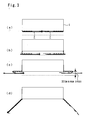
- Figure 3 is plan views which show a procedure for the developing (opening) operation of a door of an elevator control panel in Embodiment 1 of the present invention.
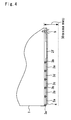
- Figure 4 is a partially expanded plan view which shows the fully closed condition of a door of a control panel.
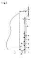
- Figure 5 is a partially enlarged plan view which shows how an outermost door of a control panel is developed (opened) by eliminating the constraint by a hold-down plate.
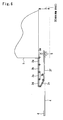
- Figure 6 is a partially enlarged plan view which shows a fully opened condition of a door in which an innermost door of a control panel is developed (opened) by further continuing the development (opening) of the door of the control panel.
- Figure 7 is a partially enlarged plan view which shows how a door is opened as a single door, with no constraint present before a control panel.
- Figure 8 is an enlarged front view of a control panel to explain the action of a hold-down plate which constrains a door so that the door does not expand.
- Figure 9 is a sectional view taken along the line A-A of Figure 8.
- Figure 10 is a sectional view taken along the line B-B of Figure 8.
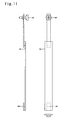
- Figure 11 is a front view and a plan view of a hold-down plate.
- the reference numeral 1 denotes an elevator control-panel main body
- the reference numeral 2 denotes a pair of right and left doors which is rotatably attached to both right and left end portions of this control-panel main body via hinges 3a.
- Each of the doors 2 blocks a half of the front face of the control-panel main body 1 so as to be capable of opening and closing the half of the front face.
- each of the doors 2 is constructed in such a manner that in the area from the outermost side to the middle part, five strip-like door units 2a to 2e which are vertically long are foldably connected by hinges 3b and that large single door units 2f which are connected by hinges 3b to the innermost door units 2e are provided in the area from the middle part to the innermost side.
- the width of the large single door unit 2f has the width of about 1/5 of the front face width of the control-panel main body 1 and is substantially equal to a total width of the four strip-like door units 2a to 2d, which are vertically long, when the number of the strip-like door units is reduced by one.
- the reference numeral 4 denotes a hold-down plate which is horizontally provided in a bridging manner in two upper and lower places of the front face of each of the doors 2 and this hold-down plate serves to prevent the door units 2a to 2e from expanding.
- the reference numeral 5 denotes a fixing jig provided in one end portion of the hold-down plate 4, and this fixing jig is connected to the hold-down plate 4 through an elongated hole of the large single door unit 2f present in an inward position of the door 2 and serves to fix the open end side to the control-panel main body 1 when the door 2 is fully closed.
- the reference numeral 6 denotes a constraining jig provided in the other end portion of the hold-down plate 4.
- this constraining jig When the door 2 is fully closed, this constraining jig is inserted into the control-panel main body 1 side (the inner side) of the outermost door unit 2a and engages thereto. When the door 2 is developed (opened), the constraint by the constraining jig 6 can be removed by causing the hold-down plate 4 to slide in the direction indicated by the arrows in Figures 8 and 10.
- Figures 3(a) and 4 show the fully closed condition of the control-panel door 2.
- the hold-down plate 4 is caused to slide in the direction indicated by the arrows in Figures 8 and 10
- the constraint of the hold-down plate 4 by the constraining jig 6 is removed and as shown in Figures 3(b) and 5, only the outermost door unit 2a is developed (opened) 90 degrees.
- the front face of the door 2 enters the inner side of a minimum space 30 at the front face of the control-panel main body 1, which is indicated by a dotted line, and there is no fear of interference with a maintenance worker and equipment.
- the development (opening) of the door 2 is further continued and the door unit 2a is developed 180 degrees.
- the door unit 2b, the door unit 2c and the door unit 2d are developed 180 degrees.
- the innermost door unit 2e is developed about 30 degrees, the large single door unit 2f which continues from the innermost door unit is stretched and developed, with the result that the front face of the control-panel main body 1 is opened in a fully opened condition.
- these series of door developing (opening) operations are all performed within the range of the minimum space at the front face of the control-panel main body 1 shown by a dotted line. In a case where there is no restraint before the control-panel main body 1, as shown in Figures 3(d) and 7, it is possible to open the door 2 in the condition of a single door as with a usual door.
- Embodiment 1 ensures that even in a case where access is made to the control panel, for example, on a car, it is possible to cause the door to be developed (opened) during maintenance work in a minimum space at the front face of the main body of the control panel without being hindered by equipment and the like, such as a safety fence installed on the car.
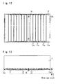
- Figure 12 is a front view of an elevator control panel in Embodiment 2 of the present invention.
- Figure 13 is a plan view of an elevator control panel in Embodiment 2 of the present invention.
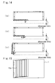
- Figure 14 is plan views which show a procedure for the developing (opening) operation of a door of an elevator control panel in Embodiment 2 of the present invention.
- the reference numeral 1 denotes an elevator control-panel main body
- the reference numeral 12 denotes a pair of right and left canopy doors which is rotatably attached to both right and left end portions of this control-panel main body via hinges 13a.
- Each of the canopy doors 12 blocks a half of the front face of the control-panel main body so as to be capable of opening and closing the half of the front face.
- Each of the canopy doors 12 is constituted by multiple strip-like door units 12a, and these strip-like door units 12a are connected to each other at top and bottom ends thereof by rotary shafts 7 so as to be capable of being developed.
- the reference numeral 15 denotes a fixing jig which fixes the canopy door 12 in a fully closed condition.
- Figure 13 shows the fully closed condition of the canopy door 12 of the control panel.
- the fixing jig 15 is detached and as shown in Figure 14(a), the development (opening) is started from the innermost door unit 12a and as shown in Figure 14(b), the development of the door units 12a is performed in order.
- Embodiment 2 ensures that even in a case where access is made to the control panel, for example, on a car, it is possible to cause the door to be developed (opened) during maintenance work in a minimum space at the front face of the main body of the control panel without being hindered by equipment and the like, such as a safety fence installed on the car.
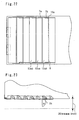
- Figure 15 is a front view of an elevator control panel in Embodiment 3 of the present invention.
- Figure 16 is an enlarged front view of the door construction of an elevator control panel in Embodiment 3 of the present invention.
- Figure 17 is an enlarged plan view which shows the developing (opening) operation of the door of an elevator control panel in Embodiment 3 of the present invention.
- the illustration of the right side of Figure 15 is omitted, the right side is the same as the left side.
- Embodiment 3 is such that in the door construction of the control panel of the machine-room-less elevator in Embodiment 2, the multiple strip-like door units 12a can be constituted by parts of the same shape.
- the shape of the multiple strip-like door units 12a is such that there are provided a rotary shaft 7a, on which the individual strip-like door units 12a are supported, and a rotary shaft 7b which supports the door unit 12a to be connected next so as to restrain the door units 12a from expanding when the door 12 closes due to a backward-and-forward-direction overlap 8 of door units 12a which adjoin each other.
- Figure 18 is a front view of an elevator control panel in Embodiment 4 of the present invention.
- Figure 19 is an enlarged front view of the door construction of an elevator control panel in Embodiment 4 of the present invention.
- Figure 20 is an enlarged plan view which shows the developing (opening) operation of a door of an elevator control panel in Embodiment 4 of the present invention.
- the illustration of the right side of Figure 18 is omitted, the right side is the same as the left side.
- the door construction of the control panel of the machine-room-less elevator in Embodiment 3 is made simple.
- the shape of the multiple strip-like door units 12a is such that there are provided a rotary shaft 7a, on which the individual strip-like door units 12a are supported, and a rotary shaft 7b which supports the door unit 12a to be connected next so as to restrain the door units 12a from expanding when the door 12 closes due to a backward-and-forward-direction overlap 8 of door units 12a which adjoin each other.
- the notch 9 in the bottom end portion of the door unit 12a is eliminated and the vertical dimension of each of the door units 12a is made longer a little from the outermost side to the innermost side.
- Figure 21 is a front view of an elevator control panel in Embodiment 5 of the present invention.
- Figure 22 is an enlarged front view of the door construction of an elevator control panel in Embodiment 5 of the present invention.
- Figure 23 is an enlarged plan view which shows the developing (opening) operation of a door of an elevator control panel in Embodiment 5 of the present invention.
- the illustration of the right side of Figure 21 is omitted, the right side is the same as the left side.
- the door construction of the control panel of the machine-room-less elevator in Embodiment 3 is such that the door units are constituted by two kinds of contoured parts 12aa, 12ab, and with these door unit parts 12aa, 12ab being alternately connected in multiple numbers, the vertical dimension on the side where the door is supported and the vertical dimension on the side where the door is opened can be made identical with each other.
- the shape of the multiple strip-like door units 12aa, 12ab is such that there are provided a rotary shaft 7a, on which the individual strip-like door units are supported, and a rotary shaft 7b which supports the door unit to be connected next so as to restrain the door units 12a from expanding when the door 12 closes due to a backward-and-forward-direction overlap 8 of the door units 12aa, 12ab which adjoin each other.
- a notch 10a is provided in the rotary shaft 7a of the door unit 12aa, whereby the angle of rotation of the door unit 12aa is obtained.
- the door unit 12ab In a portion which supports the door unit 12aa, the door unit 12ab is provided with a notch 10b for enabling the door unit 12aa to be attached, whereby the angle of rotation is obtained.
- a notch is provided in the bottom end portions of the door units 12aa, 12ab, thereby making it possible to combine parts of the same shape.
- Figure 24 shows a structure which prevents a door from opening naturally.
- the structure is constituted by a door unit 22a, an upper fixing shaft, a lower fixing shaft, an upper supporting shaft and a lower supporting shaft of the door unit.
- the elevator control panel related to the present invention can be applied to uses in which it is possible to cause the door to be developed (opened) during maintenance work in a minimum space at the front face of the main body of the control panel without being hindered by equipment and the like.
Landscapes
- Engineering & Computer Science (AREA)
- Automation & Control Theory (AREA)
- Computer Networks & Wireless Communication (AREA)
- Civil Engineering (AREA)
- Mechanical Engineering (AREA)
- Structural Engineering (AREA)
- Elevator Control (AREA)
- Elevator Door Apparatuses (AREA)
Abstract
Description
- The present invention relates to the construction of the door of an elevator control panel.
- In conventional control panels of machine-room-less elevators, in one case the construction is such that a cover of lid construction is provided at the front face of the main body of a control panel and the cover is detached in accessing to the interior of the control panel, in another case the construction is such that a set of double doors by a hinge mechanism is provided in right and left side end portions of the main body of a control panel and the double doors are opened by the hinge mechanism in accessing to the interior, and in a further case the construction is such that a slide door is capable of sliding up and down on one door cover along the front face of a control panel and the slide door is caused to slide up and down in accessing to the interior.
There have been proposed door constructions which prevent maintenance workers from falling and tools from dropping in performing the maintenance and inspection of a control panel installed within an elevator shaft from on a car (refer toPatent Document 1, for example). - Patent Document 1:
Japanese Patent Laid-Open No. 2001-341950 - In conventional control panels of machine-room-less elevators, in the case of a cover of lid construction, there is a possibility that a lid cover drops because the lid cover comes off from the control panel and in the case of a large cover, it is difficult to obtain a storage place on the car and it is very difficult to detach the cover from inside the car. When a door is opened by a hinge mechanism, the door interferes with a safety fence during maintenance work on the car and constraints with respect to the car position are great. In the case of a large door, the size of the opened door enters the standing position of a maintenance worker on the car and, therefore, this poses a problem in the safety of work. Also, it is difficult to open the door from inside the car due to the interference with a car frame and a car wall. Furthermore, in the case of a slide door, when multiple control panels connect vertically in a line, interference with control panels in lower positions occurs and, therefore, this poses the problem that a slide door cannot be used, although no problem occurs when a sufficient space is obtained below the control panels.
In the case of the door construction described inPatent Document 1, the door is constructed in such a manner that when the lid of the control panel is opened, the lid can be moved downward and can rotate. Therefore, this door construction has problems similar to those of the above-described conventional door constructions. - The present invention has been made in order to solve problems as described above and has as its object the provision of an elevator control panel which enables a door to be developed (opened) during maintenance work in a minimum space at the front face of the main body of the control panel without being hindered by equipment and the like.
- The elevator control panel related to the present invention is a control panel of a machine-room-less elevator which is installed within a shaft and to whose interior access is made by opening a door from on a car or from within the car. The control panel includes a control-panel main body and a door which is constituted by multiple strip-like door units. The door is rotatably connected to at least one side end portion of the control-panel main body and blocks a front face of the main body so as to be capable of opening and closing the front face. The multiple strip-like door units are connected so as to be capable of being folded in each other and of being developed, thereby enabling the door to be opened in a development space at the front face of the control-panel main body which has a depth dimension equal to a width of one door unit when the door is opened.
- According to the present invention, even in a case where access is made to a control panel, for example, on a car, it is possible to cause a door to be developed (opened) during maintenance work in a minimum space at the front face of the main body of the control panel without being hindered by equipment and the like, such as a safety fence installed on the car.
-
- Figure 1 is a front view of an elevator control panel in
Embodiment 1 of the present invention; - Figure 2 is a plan view of an elevator control panel in
Embodiment 1 of the present invention; - Figure 3 is plan views which show a procedure for the developing (opening) operation of a door of an elevator control panel in
Embodiment 1 of the present invention; - Figure 4 is a partially expanded plan view which shows the fully closed condition of a door of a control panel;
- Figure 5 is a partially enlarged plan view which shows how an outermost door of a control panel is developed (opened) by eliminating the constraint by a hold-down plate;
- Figure 6 is a partially enlarged plan view which shows a fully opened condition of a door in which an innermost door of a control panel is developed (opened) by further continuing the development (opening) of the door of the control panel;
- Figure 7 is a partially enlarged plan view which shows how a door is opened as a single door, with no restraint present before a control panel;
- Figure 8 is an enlarged front view of a control panel to explain the action of a hold-down plate which constrains a door so that the door does not expand;
- Figure 9 is a sectional view taken along the line A-A of Figure 8;
- Figure 10 is a sectional view taken along the line B-B of Figure 8;
- Figure 11 is a front view and a plan view of a hold-down plate;
- Figure 12 is a front view of an elevator control panel in
Embodiment 2 of the present invention; - Figure 13 is a plan view of an elevator control panel in
Embodiment 2 of the present invention; - Figure 14 is plan views which show a procedure for the developing (opening) operation of a door of an elevator control panel in
Embodiment 2 of the present invention; - Figure 15 is a front view of an elevator control panel in
Embodiment 3 of the present invention; - Figure 16 is an enlarged front view of the door construction of an elevator control panel in
Embodiment 3 of the present invention; - Figure 17 is an enlarged plan view which shows the developing (opening) operation of the door of an elevator control panel in
Embodiment 3 of the present invention; - Figure 18 is a front view of an elevator control panel in
Embodiment 4 of the present invention; - Figure 19 is an enlarged front view of the door construction of an elevator control panel in
Embodiment 4 of the present invention; - Figure 20 is an enlarged plan view which shows the developing (opening) operation of a door of an elevator control panel in
Embodiment 4 of the present invention; - Figure 21 is a front view of an elevator control panel in
Embodiment 5 of the present invention; - Figure 22 is an enlarged front view of the door construction of an elevator control panel in
Embodiment 5 of the present invention; - Figure 23 is an enlarged plan view which shows the developing (opening) operation of a door of an elevator control panel in
Embodiment 5 of the present invention; and - Figure 24 is diagrams of a structure which prevents a door from opening naturally.
-
- 1
- Elevator control-panel main body
- 2, 12
- Door
- 2a to 2e, 12a
- Strip-like door unit
- 2f
- Large single door unit
- 3, 3a, 3b
- Hinge
- 4
- Hold-down plate
- 5
- Fixing jig
- 6
- Constraining jig
- 7, 7a, 7b
- Rotary shaft
- 8
- Overlap
- 9
- Notch
- 30
- Minimum space
- The present invention will be described in further detail according to the accompanying drawings.
- Figure 1 is a front view of an elevator control panel in
Embodiment 1 of the present invention. Figure 2 is a plan view of an elevator control panel inEmbodiment 1 of the present invention. Figure 3 is plan views which show a procedure for the developing (opening) operation of a door of an elevator control panel inEmbodiment 1 of the present invention. Figure 4 is a partially expanded plan view which shows the fully closed condition of a door of a control panel. Figure 5 is a partially enlarged plan view which shows how an outermost door of a control panel is developed (opened) by eliminating the constraint by a hold-down plate. Figure 6 is a partially enlarged plan view which shows a fully opened condition of a door in which an innermost door of a control panel is developed (opened) by further continuing the development (opening) of the door of the control panel. Figure 7 is a partially enlarged plan view which shows how a door is opened as a single door, with no constraint present before a control panel. Figure 8 is an enlarged front view of a control panel to explain the action of a hold-down plate which constrains a door so that the door does not expand. Figure 9 is a sectional view taken along the line A-A of Figure 8. Figure 10 is a sectional view taken along the line B-B of Figure 8. Figure 11 is a front view and a plan view of a hold-down plate. - In a control panel of a machine-room-less elevator, it is required that a door be capable of being developed (opened) in a minimum space at the front face of the main body of the control panel. A description will be given of the door construction of an elevator control-panel main body of the present invention made in order to meet this requirement by using the drawings.
Thereference numeral 1 denotes an elevator control-panel main body, and thereference numeral 2 denotes a pair of right and left doors which is rotatably attached to both right and left end portions of this control-panel main body viahinges 3a. Each of thedoors 2 blocks a half of the front face of the control-panelmain body 1 so as to be capable of opening and closing the half of the front face. InEmbodiment 1, each of thedoors 2 is constructed in such a manner that in the area from the outermost side to the middle part, five strip-like door units 2a to 2e which are vertically long are foldably connected byhinges 3b and that largesingle door units 2f which are connected byhinges 3b to theinnermost door units 2e are provided in the area from the middle part to the innermost side. The width of the largesingle door unit 2f has the width of about 1/5 of the front face width of the control-panelmain body 1 and is substantially equal to a total width of the four strip-like door units 2a to 2d, which are vertically long, when the number of the strip-like door units is reduced by one. Thereference numeral 4 denotes a hold-down plate which is horizontally provided in a bridging manner in two upper and lower places of the front face of each of thedoors 2 and this hold-down plate serves to prevent thedoor units 2a to 2e from expanding. Thereference numeral 5 denotes a fixing jig provided in one end portion of the hold-down plate 4, and this fixing jig is connected to the hold-down plate 4 through an elongated hole of the largesingle door unit 2f present in an inward position of thedoor 2 and serves to fix the open end side to the control-panelmain body 1 when thedoor 2 is fully closed. Thereference numeral 6 denotes a constraining jig provided in the other end portion of the hold-down plate 4. When thedoor 2 is fully closed, this constraining jig is inserted into the control-panelmain body 1 side (the inner side) of theoutermost door unit 2a and engages thereto. When thedoor 2 is developed (opened), the constraint by the constrainingjig 6 can be removed by causing the hold-down plate 4 to slide in the direction indicated by the arrows in Figures 8 and 10. - Next, a procedure for developing (opening) the door of the elevator control panel will be described by using Figures 3 to 6.
Figures 3(a) and 4 show the fully closed condition of the control-panel door 2. In this state, the hold-down plate 4 is caused to slide in the direction indicated by the arrows in Figures 8 and 10, the constraint of the hold-down plate 4 by the constrainingjig 6 is removed and as shown in Figures 3(b) and 5, only theoutermost door unit 2a is developed (opened) 90 degrees. At this time, the front face of thedoor 2 enters the inner side of aminimum space 30 at the front face of the control-panelmain body 1, which is indicated by a dotted line, and there is no fear of interference with a maintenance worker and equipment. Furthermore, the development (opening) of thedoor 2 is further continued and thedoor unit 2a is developed 180 degrees. Subsequently, thedoor unit 2b, thedoor unit 2c and thedoor unit 2d are developed 180 degrees. Then, as shown in Figures 3(c) and 6, theinnermost door unit 2e is developed about 30 degrees, the largesingle door unit 2f which continues from the innermost door unit is stretched and developed, with the result that the front face of the control-panelmain body 1 is opened in a fully opened condition. And these series of door developing (opening) operations are all performed within the range of the minimum space at the front face of the control-panelmain body 1 shown by a dotted line.
In a case where there is no restraint before the control-panelmain body 1, as shown in Figures 3(d) and 7, it is possible to open thedoor 2 in the condition of a single door as with a usual door. - Next, a description will be given of the action of the hold-
down plate 4 which constraints thedoor 2 of the elevator control panel so that thedoor 2 does not expand in a fully closed condition by using Figures 8 to 10.
That is, when thedoor 2 is in a fully closed condition, the hold-down plate 4 on the upper side of Figure 8 is caused to slide in the direction reverse to the arrow as shown in Figure 9, whereby the constrainingjig 6 provided in the other end portion of the hold-down plate 4 is inserted into the inner side of theoutermost door unit 2a and caused to engage therewith and, at the same time, this constraining jig is fixed by the fixingjig 5 provided in one end portion of the hold-down plate 4. As a result of this, the movement of thedoor units 2a to 2f which compose thedoor 2 is constrained by the hold-down plate 4. When the constraint of the hold-down plate 4 is released from this fully closed condition, the fixing by the fixingjig 5 provided in one end portion of the hold-down plate 4 is removed and subsequently the hold-down plate 4 on the lower side of Figure 8 is caused to slide in the direction of the arrow along the elongated hole of thedoor unit 2f as shown in Figure 10, whereby the inserted and engaged condition between the constrainingjig 6 in the other end portion of the hold-down plate 4 and the inner side of theoutermost door unit 2a is removed, with the result that it is possible to bring thedoor 2 into a condition which permits development (opening). - Therefore, the adoption of the constituent of
Embodiment 1 ensures that even in a case where access is made to the control panel, for example, on a car, it is possible to cause the door to be developed (opened) during maintenance work in a minimum space at the front face of the main body of the control panel without being hindered by equipment and the like, such as a safety fence installed on the car. - Figure 12 is a front view of an elevator control panel in
Embodiment 2 of the present invention. Figure 13 is a plan view of an elevator control panel inEmbodiment 2 of the present invention. Figure 14 is plan views which show a procedure for the developing (opening) operation of a door of an elevator control panel inEmbodiment 2 of the present invention. - In a control panel of a machine-room-less elevator, by using a canopy door of snake construction (canopy type), the door can be developed (opened) in a minimum space at the front face of the control-panel main body.
Thereference numeral 1 denotes an elevator control-panel main body, and thereference numeral 12 denotes a pair of right and left canopy doors which is rotatably attached to both right and left end portions of this control-panel main body viahinges 13a. Each of thecanopy doors 12 blocks a half of the front face of the control-panel main body so as to be capable of opening and closing the half of the front face. Each of thecanopy doors 12 is constituted by multiple strip-like door units 12a, and these strip-like door units 12a are connected to each other at top and bottom ends thereof byrotary shafts 7 so as to be capable of being developed. Thereference numeral 15 denotes a fixing jig which fixes thecanopy door 12 in a fully closed condition. - Next, a procedure for developing (opening) the door of the elevator control panel will be described by using Figures 13 and 14. Incidentally, although the illustration of the right side of Figure 14 is omitted, the right side is the same as the left side.
Figure 13 shows the fully closed condition of thecanopy door 12 of the control panel. In this state, the fixingjig 15 is detached and as shown in Figure 14(a), the development (opening) is started from theinnermost door unit 12a and as shown in Figure 14(b), the development of thedoor units 12a is performed in order. Lastly, as shown in Figure 14(c), the front face of the control-panelmain body 1 is opened in a fully opened condition, and it is possible to position the whole of thecanopy door 12 on the outer surface of both right and left side walls of the control-panelmain body 1. And these series of door developing (opening) operations are all performed within the range of the minimum space at the front face of the control-panelmain body 1 shown by a dotted line. - Therefore, the adoption of the constituent of
Embodiment 2 ensures that even in a case where access is made to the control panel, for example, on a car, it is possible to cause the door to be developed (opened) during maintenance work in a minimum space at the front face of the main body of the control panel without being hindered by equipment and the like, such as a safety fence installed on the car. - Figure 15 is a front view of an elevator control panel in
Embodiment 3 of the present invention. Figure 16 is an enlarged front view of the door construction of an elevator control panel inEmbodiment 3 of the present invention. Figure 17 is an enlarged plan view which shows the developing (opening) operation of the door of an elevator control panel inEmbodiment 3 of the present invention. Incidentally, although the illustration of the right side of Figure 15 is omitted, the right side is the same as the left side. -
Embodiment 3 is such that in the door construction of the control panel of the machine-room-less elevator inEmbodiment 2, the multiple strip-like door units 12a can be constituted by parts of the same shape.
The shape of the multiple strip-like door units 12a is such that there are provided arotary shaft 7a, on which the individual strip-like door units 12a are supported, and arotary shaft 7b which supports thedoor unit 12a to be connected next so as to restrain thedoor units 12a from expanding when thedoor 12 closes due to a backward-and-forward-direction overlap 8 ofdoor units 12a which adjoin each other. - Figure 18 is a front view of an elevator control panel in
Embodiment 4 of the present invention. Figure 19 is an enlarged front view of the door construction of an elevator control panel inEmbodiment 4 of the present invention. Figure 20 is an enlarged plan view which shows the developing (opening) operation of a door of an elevator control panel inEmbodiment 4 of the present invention. Incidentally, although the illustration of the right side of Figure 18 is omitted, the right side is the same as the left side. - In
Embodiment 4, the door construction of the control panel of the machine-room-less elevator inEmbodiment 3 is made simple.
The shape of the multiple strip-like door units 12a is such that there are provided arotary shaft 7a, on which the individual strip-like door units 12a are supported, and arotary shaft 7b which supports thedoor unit 12a to be connected next so as to restrain thedoor units 12a from expanding when thedoor 12 closes due to a backward-and-forward-direction overlap 8 ofdoor units 12a which adjoin each other. Thenotch 9 in the bottom end portion of thedoor unit 12a is eliminated and the vertical dimension of each of thedoor units 12a is made longer a little from the outermost side to the innermost side. - Figure 21 is a front view of an elevator control panel in
Embodiment 5 of the present invention. Figure 22 is an enlarged front view of the door construction of an elevator control panel inEmbodiment 5 of the present invention. Figure 23 is an enlarged plan view which shows the developing (opening) operation of a door of an elevator control panel inEmbodiment 5 of the present invention. Incidentally, although the illustration of the right side of Figure 21 is omitted, the right side is the same as the left side. - In
Embodiment 5, the door construction of the control panel of the machine-room-less elevator inEmbodiment 3 is such that the door units are constituted by two kinds of contoured parts 12aa, 12ab, and with these door unit parts 12aa, 12ab being alternately connected in multiple numbers, the vertical dimension on the side where the door is supported and the vertical dimension on the side where the door is opened can be made identical with each other.
The shape of the multiple strip-like door units 12aa, 12ab is such that there are provided arotary shaft 7a, on which the individual strip-like door units are supported, and arotary shaft 7b which supports the door unit to be connected next so as to restrain thedoor units 12a from expanding when thedoor 12 closes due to a backward-and-forward-direction overlap 8 of the door units 12aa, 12ab which adjoin each other. In order to eliminate the fact that the angle of rotation cannot be obtained because of the interference of the door unit 12aa with the door unit 12ab which occurs when the door unit 12aa is developed, anotch 10a is provided in therotary shaft 7a of the door unit 12aa, whereby the angle of rotation of the door unit 12aa is obtained. In a portion which supports the door unit 12aa, the door unit 12ab is provided with a notch 10b for enabling the door unit 12aa to be attached, whereby the angle of rotation is obtained. A notch is provided in the bottom end portions of the door units 12aa, 12ab, thereby making it possible to combine parts of the same shape. - Incidentally, Figure 24 shows a structure which prevents a door from opening naturally.
The structure is constituted by adoor unit 22a, an upper fixing shaft, a lower fixing shaft, an upper supporting shaft and a lower supporting shaft of the door unit. By laying out the positional relationship between the upper fixing shaft and the lower fixing shaft in the backward and forward direction, with the upper fixing shaft shifted to the inner side of thedoor unit 22a and the lower fixing shaft shifted to the front side, the supporting shaft side of thedoor unit 22a is raised upward when thedoor unit 22a opens. Therefore, thedoor unit 22a is restricted from expanding from a closed condition. - As described above, the elevator control panel related to the present invention can be applied to uses in which it is possible to cause the door to be developed (opened) during maintenance work in a minimum space at the front face of the main body of the control panel without being hindered by equipment and the like.
Claims (6)
- A control panel of a machine-room-less elevator which is installed within a shaft and to whose interior access is made by opening a door from on a car or from within the car during maintenance work, characterized in that the control panel comprises a control-panel main body and a door which is constituted by multiple strip-like door units, the door being rotatably connected to at least one side end portion of the control-panel main body and blocking a front face of the main body so as to be capable of opening and closing the front face, and in that the multiple strip-like door units are connected so as to be capable of being folded in each other and of being developed, thereby enabling the door to be opened in a development space at the front face of the control-panel main body which has a depth dimension equal to a width of one door unit when the door is opened.
- The elevator control panel according to claim 1, characterized in that the multiple strip-like door units have a hold-down plate which prevents the door units from expanding outward.
- The elevator control panel according to claim 1 or 2, characterized in that the multiple strip-like door units are connected to each other by use of hinges.
- The elevator control panel according to claim 1, characterized in that the multiple strip-like door units provide a canopy door of snake construction, and in that the multiple strip-like door units are connected to each other at top and bottom ends thereof by rotary shafts so that it is possible to cause part of each of the strip-like door units to overlap at the front face of the control-panel main body.
- The elevator control panel according to claim 4, characterized in that the canopy door of snake construction is constituted by combinations of the same parts.
- The elevator control panel according to claim 4, characterized in that the canopy door of snake construction is constituted by alternately combining two kinds of parts so that top and bottom ends of the door are horizontally symmetrical.
Applications Claiming Priority (2)
| Application Number | Priority Date | Filing Date | Title |
|---|---|---|---|
| JP2005125684A JP2006298621A (en) | 2005-04-22 | 2005-04-22 | Elevator control panel |
| PCT/JP2006/307358 WO2006115008A1 (en) | 2005-04-22 | 2006-04-06 | Elevator control panel |
Publications (2)
| Publication Number | Publication Date |
|---|---|
| EP1873107A1 true EP1873107A1 (en) | 2008-01-02 |
| EP1873107A4 EP1873107A4 (en) | 2013-01-30 |
Family
ID=37214636
Family Applications (1)
| Application Number | Title | Priority Date | Filing Date |
|---|---|---|---|
| EP06731306A Withdrawn EP1873107A4 (en) | 2005-04-22 | 2006-04-06 | ELEVATOR CONTROL PANEL |
Country Status (5)
| Country | Link |
|---|---|
| EP (1) | EP1873107A4 (en) |
| JP (1) | JP2006298621A (en) |
| KR (1) | KR100904119B1 (en) |
| CN (1) | CN101068738B (en) |
| WO (1) | WO2006115008A1 (en) |
Families Citing this family (6)
| Publication number | Priority date | Publication date | Assignee | Title |
|---|---|---|---|---|
| CN101588980B (en) * | 2007-02-27 | 2012-03-07 | 三菱电机株式会社 | Elevator control panel |
| CN101784470B (en) * | 2007-08-31 | 2012-07-04 | 三菱电机株式会社 | Elevator controller |
| JP6213389B2 (en) * | 2014-06-18 | 2017-10-18 | 三菱電機株式会社 | Elevator control device |
| WO2019053831A1 (en) * | 2017-09-13 | 2019-03-21 | 三菱電機株式会社 | Elevator device |
| EP3564174B1 (en) | 2018-05-03 | 2021-06-30 | Otis Elevator Company | Openable elevator car wall panels |
| JP7682118B2 (en) * | 2022-03-14 | 2025-05-23 | 株式会社日立製作所 | Control device and elevator device |
Family Cites Families (4)
| Publication number | Priority date | Publication date | Assignee | Title |
|---|---|---|---|---|
| JPS56126103U (en) * | 1980-02-22 | 1981-09-25 | ||
| FR2614885B1 (en) * | 1987-05-05 | 1989-06-30 | Slycma Ste Lyon Const Mat Asce | ACCORDION-TYPE DOOR DRIVE MECHANISM FOR ELEVATOR CABS |
| ATE194128T1 (en) * | 1997-11-08 | 2000-07-15 | Thyssen Aufzugswerke Gmbh | ELEVATOR, ESPECIALLY DRIVE ELEVATOR |
| JP4254322B2 (en) * | 2003-04-16 | 2009-04-15 | フジテック株式会社 | Elevator equipment |
-
2005
- 2005-04-22 JP JP2005125684A patent/JP2006298621A/en active Pending
-
2006
- 2006-04-06 CN CN2006800012642A patent/CN101068738B/en not_active Expired - Fee Related
- 2006-04-06 KR KR1020077011407A patent/KR100904119B1/en not_active Expired - Fee Related
- 2006-04-06 WO PCT/JP2006/307358 patent/WO2006115008A1/en not_active Ceased
- 2006-04-06 EP EP06731306A patent/EP1873107A4/en not_active Withdrawn
Also Published As
| Publication number | Publication date |
|---|---|
| KR100904119B1 (en) | 2009-06-24 |
| KR20070084385A (en) | 2007-08-24 |
| EP1873107A4 (en) | 2013-01-30 |
| WO2006115008A1 (en) | 2006-11-02 |
| CN101068738B (en) | 2011-01-12 |
| CN101068738A (en) | 2007-11-07 |
| JP2006298621A (en) | 2006-11-02 |
Similar Documents
| Publication | Publication Date | Title |
|---|---|---|
| EP1873107A1 (en) | Elevator control panel | |
| EP3088342A1 (en) | Maintenance platform | |
| EP1925581A1 (en) | Car upper side handrail device of elevator | |
| KR20120003577U (en) | The Maintenance Hatch of Ceiling Panel in Deck House | |
| US7918053B2 (en) | Container | |
| JP2007106512A (en) | Elevator control device | |
| US20040128915A1 (en) | Door for automated machine | |
| EP3280665B1 (en) | Accessible elevator buffer | |
| JP4937354B2 (en) | Elevator control device | |
| JP4834436B2 (en) | Switch box for elevator car operation panel | |
| JP4917146B2 (en) | Elevator control panel | |
| KR20140002151U (en) | Opening and Closing Apparatus of Fixed Ladder | |
| JP2009096618A (en) | Elevator car operation panel device | |
| US20220348440A1 (en) | Door frame for an elevator system | |
| JP6194510B2 (en) | Elevator cab | |
| KR20030064328A (en) | Sash system having doors being openable and closable by sliding and folding | |
| JP2008297056A (en) | Passenger conveyor floorboard | |
| JP2007284228A (en) | Elevator operation panel device | |
| JP2007031109A (en) | Elevator equipment | |
| KR20210055488A (en) | Hatch assembly | |
| JP2011037617A (en) | Cage of elevator | |
| JP4849439B2 (en) | Smoke shield for elevator hall door device | |
| KR100530133B1 (en) | Apparatus for opening trunk lid in vehicle | |
| KR20140003422U (en) | Sliding cover for lashing platform | |
| KR200432557Y1 (en) | Apparatus of gateway for a bridge-beam |
Legal Events
| Date | Code | Title | Description |
|---|---|---|---|
| PUAI | Public reference made under article 153(3) epc to a published international application that has entered the european phase |
Free format text: ORIGINAL CODE: 0009012 |
|
| 17P | Request for examination filed |
Effective date: 20070522 |
|
| AK | Designated contracting states |
Kind code of ref document: A1 Designated state(s): DE |
|
| DAX | Request for extension of the european patent (deleted) | ||
| RBV | Designated contracting states (corrected) |
Designated state(s): DE |
|
| A4 | Supplementary search report drawn up and despatched |
Effective date: 20130107 |
|
| RIC1 | Information provided on ipc code assigned before grant |
Ipc: B66B 11/00 20060101ALI20121221BHEP Ipc: B66B 1/34 20060101AFI20121221BHEP |
|
| STAA | Information on the status of an ep patent application or granted ep patent |
Free format text: STATUS: THE APPLICATION IS DEEMED TO BE WITHDRAWN |
|
| 18D | Application deemed to be withdrawn |
Effective date: 20130806 |