EP1873055A1 - Ship with bow control surface - Google Patents
Ship with bow control surface Download PDFInfo
- Publication number
- EP1873055A1 EP1873055A1 EP06116486A EP06116486A EP1873055A1 EP 1873055 A1 EP1873055 A1 EP 1873055A1 EP 06116486 A EP06116486 A EP 06116486A EP 06116486 A EP06116486 A EP 06116486A EP 1873055 A1 EP1873055 A1 EP 1873055A1
- Authority
- EP
- European Patent Office
- Prior art keywords
- ship
- bow
- ship according
- control surface
- hull
- Prior art date
- Legal status (The legal status is an assumption and is not a legal conclusion. Google has not performed a legal analysis and makes no representation as to the accuracy of the status listed.)
- Withdrawn
Links
- XLYOFNOQVPJJNP-UHFFFAOYSA-N water Substances O XLYOFNOQVPJJNP-UHFFFAOYSA-N 0.000 claims abstract description 10
- 230000033001 locomotion Effects 0.000 description 9
- 230000008859 change Effects 0.000 description 6
- 238000010276 construction Methods 0.000 description 2
- 230000001419 dependent effect Effects 0.000 description 2
- 230000000694 effects Effects 0.000 description 2
- 230000007246 mechanism Effects 0.000 description 2
- 230000009471 action Effects 0.000 description 1
- 230000009286 beneficial effect Effects 0.000 description 1
- 230000008901 benefit Effects 0.000 description 1
- 230000005540 biological transmission Effects 0.000 description 1
- 230000003247 decreasing effect Effects 0.000 description 1
- 230000000368 destabilizing effect Effects 0.000 description 1
- 230000006872 improvement Effects 0.000 description 1
- 238000005259 measurement Methods 0.000 description 1
- 230000009467 reduction Effects 0.000 description 1
- 238000005096 rolling process Methods 0.000 description 1
Images



Classifications
-
- B—PERFORMING OPERATIONS; TRANSPORTING
- B63—SHIPS OR OTHER WATERBORNE VESSELS; RELATED EQUIPMENT
- B63B—SHIPS OR OTHER WATERBORNE VESSELS; EQUIPMENT FOR SHIPPING
- B63B1/00—Hydrodynamic or hydrostatic features of hulls or of hydrofoils
- B63B1/02—Hydrodynamic or hydrostatic features of hulls or of hydrofoils deriving lift mainly from water displacement
- B63B1/04—Hydrodynamic or hydrostatic features of hulls or of hydrofoils deriving lift mainly from water displacement with single hull
- B63B1/06—Shape of fore part
-
- B—PERFORMING OPERATIONS; TRANSPORTING
- B63—SHIPS OR OTHER WATERBORNE VESSELS; RELATED EQUIPMENT
- B63B—SHIPS OR OTHER WATERBORNE VESSELS; EQUIPMENT FOR SHIPPING
- B63B39/00—Equipment to decrease pitch, roll, or like unwanted vessel movements; Apparatus for indicating vessel attitude
- B63B39/06—Equipment to decrease pitch, roll, or like unwanted vessel movements; Apparatus for indicating vessel attitude to decrease vessel movements by using foils acting on ambient water
-
- B—PERFORMING OPERATIONS; TRANSPORTING
- B63—SHIPS OR OTHER WATERBORNE VESSELS; RELATED EQUIPMENT
- B63H—MARINE PROPULSION OR STEERING
- B63H25/00—Steering; Slowing-down otherwise than by use of propulsive elements; Dynamic anchoring, i.e. positioning vessels by means of main or auxiliary propulsive elements
- B63H25/06—Steering by rudders
-
- B—PERFORMING OPERATIONS; TRANSPORTING
- B63—SHIPS OR OTHER WATERBORNE VESSELS; RELATED EQUIPMENT
- B63H—MARINE PROPULSION OR STEERING
- B63H25/00—Steering; Slowing-down otherwise than by use of propulsive elements; Dynamic anchoring, i.e. positioning vessels by means of main or auxiliary propulsive elements
- B63H25/06—Steering by rudders
- B63H25/38—Rudders
-
- B—PERFORMING OPERATIONS; TRANSPORTING
- B63—SHIPS OR OTHER WATERBORNE VESSELS; RELATED EQUIPMENT
- B63H—MARINE PROPULSION OR STEERING
- B63H25/00—Steering; Slowing-down otherwise than by use of propulsive elements; Dynamic anchoring, i.e. positioning vessels by means of main or auxiliary propulsive elements
- B63H25/44—Steering or slowing-down by extensible flaps or the like
-
- B—PERFORMING OPERATIONS; TRANSPORTING
- B63—SHIPS OR OTHER WATERBORNE VESSELS; RELATED EQUIPMENT
- B63B—SHIPS OR OTHER WATERBORNE VESSELS; EQUIPMENT FOR SHIPPING
- B63B1/00—Hydrodynamic or hydrostatic features of hulls or of hydrofoils
- B63B1/02—Hydrodynamic or hydrostatic features of hulls or of hydrofoils deriving lift mainly from water displacement
- B63B1/04—Hydrodynamic or hydrostatic features of hulls or of hydrofoils deriving lift mainly from water displacement with single hull
- B63B1/06—Shape of fore part
- B63B2001/066—Substantially vertical stems
-
- B—PERFORMING OPERATIONS; TRANSPORTING
- B63—SHIPS OR OTHER WATERBORNE VESSELS; RELATED EQUIPMENT
- B63H—MARINE PROPULSION OR STEERING
- B63H25/00—Steering; Slowing-down otherwise than by use of propulsive elements; Dynamic anchoring, i.e. positioning vessels by means of main or auxiliary propulsive elements
- B63H25/06—Steering by rudders
- B63H2025/063—Arrangements of rudders forward of the propeller position, e.g. of backing rudders; Arrangements of rudders on the forebody of the hull; Steering gear therefor
-
- Y—GENERAL TAGGING OF NEW TECHNOLOGICAL DEVELOPMENTS; GENERAL TAGGING OF CROSS-SECTIONAL TECHNOLOGIES SPANNING OVER SEVERAL SECTIONS OF THE IPC; TECHNICAL SUBJECTS COVERED BY FORMER USPC CROSS-REFERENCE ART COLLECTIONS [XRACs] AND DIGESTS
- Y02—TECHNOLOGIES OR APPLICATIONS FOR MITIGATION OR ADAPTATION AGAINST CLIMATE CHANGE
- Y02T—CLIMATE CHANGE MITIGATION TECHNOLOGIES RELATED TO TRANSPORTATION
- Y02T70/00—Maritime or waterways transport
- Y02T70/10—Measures concerning design or construction of watercraft hulls
Definitions
- the invention concerns a ship in accordance with the preamble of claim 1.
- Broaching is the peculiar ship behaviour, which consists of a coupled yaw-, sway- and roll motion. Ships may experience this broach motion in the described wave condition and once it occurs it can lead to seriously large roll angles and eventually end in a "capsize”.
- the broaching phenomenon may be roughly explained as follows: In stern quartering and following waves the ship stern is lifted asymmetrically by the incoming wave and it starts the ship to heel (and also pitch). Broaching is particularly prone in waves with a wave length close to the ship length. So simultaneously the ship puts its bow in the face of the (next) wave. Caused by the asymmetry of the hull due to the introduced heeling angle and the directionally destabilizing effect of the now deeply immersed bow sections the ship starts to yaw. Combined with the forward speed this may lead to an increase in the heeling angle which on its turn worsens the hull asymmetry and therewith to further course instability. This may lead to the ship coming beam side to the waves in principal a potentially dangerous situation as it may lead to an even further increase in heel.
- Ships are normally directionally controlled by either a helmsman or an autopilot.
- the applied control is aimed at keeping the ship on a preset course. From experience, full scale and model scale measurements it is known that this directional control applied in following waves worsens the broaching behaviour of the ship, due to the unfavourable phase between the steering force applied and the herewith induced heeling moment.
- the ship is in accordance with claim 1.
- the resistance against broaching is increased by using the additional control surface for directional control and to make beneficial use of the forces generated by this surface for controlling the roll and sway motion.
- this control surface may be regarded as an additional control surface for controlling both yaw and heel simultaneously.
- the following improvement occurs: In the situation that the ship sails in stern quartering waves from starboard the stern can be lifted by a wave where after the ship starts to heel to port. The asymmetry of the hull underwater shape induces a yawing moment trying to turn the ship to starboard. Corrective action is applied on the control surface near the bow to correct this course change and the force asked for is a lateral force directed to port. This force implies a rolling motion to starboard and so decreasing the heeling angle.
- the ship is according to claim 2.
- a ship of this design is especially favourably for the application of this invention.
- Such a ship is known from the publication Keuning, J.A.; Toxopeus, S.; Pinkster, J.; The effect of bow-shape on the seakeeping performance of a fast monohull; Proceedings of FAST 2001 conference, September 2001; page 197-206; ISBN 0 903055 70 8, publisher The Royal Institute of Naval Architects .
- the ship is described as the AXE BOW design.
- the increased draught and increased freeboard makes the ship suitable for sailing through heavy seas while ensuring that the control surface remains in heavy seas sufficiently submerged.
- the ship is according to claim 3.
- the more or less vertical bow is particularly suitably for incorporating a control surface according to the invention
- the ship is according to claim 4.
- This fillet radius makes it possible to reduce the length of the ship and so reducing the wet surface and the flow resistance without disadvantageously influencing the ships behavior in waves.
- the ship is according to claim 5. This improves the ships behavior in heavy seas as the added resistance in waves is reduced.
- the ship is according to claim 6. This makes for a simple construction with effective steering and control capabilities.
- the ship is according to claim 7. This makes for an easy construction with good water flow along the hull, thereby minimizing additional drag when not activated.
- the ship is according to claim 8. This embodiment combines at high speeds good control capabilities with high efficiency.
- the ship is according to claim 9. In this way the reducing of the heeling and broaching can be combined in an easy way.
- the ship is according to claim 10.
- the use of the control surface can be manually adapted to the changing circumstances and wave conditions.
- the ship is according to claim 11.
- the use of the control surface is adapted automatically to the changing circumstances and wave conditions.
- the ship is according to claim 12.
- the control surface is only activated when its use improves the ships behaviour.
- Figure 1 shows a ship 1 which is designed in accordance with the body plan according to figure 2.
- the ship 1 is designed for high speeds and has a single long and slender hull, whereby the length of the hull is at least five times the beam and for longer ships as much as seven to eight times the beam. In shorter ships the beam is relatively larger as the hull must include the propulsion means and a wider beam ensures that there remains sufficient stability.
- the ship 1 in an aft ship 11 has one or more propellers 9 and one or more aft rudders 10.
- the lay out on deck is as usual for instance with a wheel house 2.
- In the bow 4 there is a bow rudder 5 of which the function will be explained later.
- the hull of the ship 1 has a special design, in more detail the design is such that a reduction of the Froude Kriloff forces in particular in the foreship 3 is achieved by minimizing the change in momentaneous submerged volume of the hull with sides 8 whilst it makes larger relative motions relative to the water level due to waves or the ships motions.
- a further measure in the design is to reduce the change in waterline beam of the sections in particular in the foreship whilst it makes the foresaid larger relative motions. This implies there is a minimal flare in the bow sections and a bow 4 has a more or less vertical line or the bow 4 extends less than 30 degrees forward.
- the amount of increased shear in the foreship 3 is dependent on ship size, speed and wave climate involved.
- a downwards sloping centre line towards the foreship 3 prevents the sections there to leave and re-enter the water whilst the ship 1 is performing larger relative motions.
- the amount of negative slope in the bottom 7 is dependent on ship size, speed and wave climate involved.
- the deadrise angle of the sections from bow to stern is carefully determined in order to minimize exciting forces and yet maintain sufficient hydrodynamic lift with minimal resistance.
- the shape of the hull is such that the hull is long and slender, there is no flare in the bow sections and the sides 8 at the bow sections are almost vertical. Near the bow 4 the sides 8 make an angle ⁇ seen in a horizontal plane which is smaller than 40 degrees. There is an increased sheer forward and down sloping centreline forward and the entry of the waterlines are rounded. In order to reduce the wet surface the bow 4 is rounded with a radius R of at least 0,1m. Depending on the beam of the ship the radius can be at least 1% of the beam.
- FIGS 3 and 4 show the behaviour of ship 1 in waves W that approach the aft ship 11 from the stern quarter.
- a water level s is the normal situation when the ship 1 is level.
- the waves W push against the port side 8 of the aft ship 11 and change the direction of the ships axis 1 from the on course situation indicated with 12 to the off course direction whereby the ships axis is indicated with 1' and the ship is indicated with 13.
- the ship 1 When the ship 1 is off course the ship 1 can be brought on course using aft rudders 10. These rudders 10 are then brought in a position as shown in figure 3 and 4 and a force A is generated on the aft rudders 10. This force creates with the force of the waves W a tilting torque. Summarized the forces A on the aft rudders 10 reinforce the forces of the waves W on the side 8. If the ship 1 is brought on course using a bow rudder 5 a force B is generated on the bow rudder 5. This force B has the same direction as the force generated by the waves W and so counteracts the tilting torque of the waves W.
- the bow rudder 5 is only used when the waves W coming in side ways result in the course change as indicated before when waves are coming in from the stern quarter of the ship 1. In the situation whereby the ship 1 is designed with its maximum draught in the foreship 3, as described before, waves W coming in sideways or a few compass points forward will result in the same behaviour and the use of the bow rudder 5 is then also an advantage.
- the ship 1 is provided with means to switch over from steering with the aft rudder 10 to steering with the bow rudder 5 or with both rudders.
- the switching over can be effected by manually indicating to the automatic steering system from which direction waves W are coming in, which steering system will then take this information into account.
- the automatic steering system can also include an algorithm for calculating the direction from which the waves W are coming in.
- the automatic system is then provided with sensors for determining the movements of the ship 1, for instance using gyroscopes.
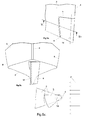
- FIGs 5a, 5b and 5c show the bow rudder 5 mounted in the foreship 3 in more detail.
- the bow rudder 5 is the lowest part of the bow 4 and has a rotation axis 14 which is more or less vertical.
- the bow rudder 5 is shaped such that when it is in its middle position the contour of the rudder 5 follows the shape of the hull as indicated in figure 2 and the water flow F is not influenced by the bow rudder 5.
- Part of the bow rudder 5 is in front of the rotation axis 14 so that the torque for rotating the bow rudder 5 is partly balanced, similar as can be used in known rudders.
- the rotation of the bow rudder 5 is effected in the same manner as usual with known rudders.
- FIGs 6a and 6b show a second embodiment of the bow 4 of the ship 1.
- the lateral forces B for steering the ship 1 are now generated by the flow F along a side flap 16.
- these side flaps 16 rotate around a more or less vertical axis 17, which axis 17 is supported at the lowest part of the bow 4 by a support 15.
- the side flaps 16 follow the contour of the foreship 3 and are positioned against a brace 18.
- This mechanism 19 can be formed by two hinged levers connected to each other and respectively the foreship 3 and the side flap 16.
- the hinge connecting these levers can be moved in vertical direction by a hydraulic cylinder (not shown).
- This hydraulic cylinder can be located above the water level and is controlled such that either the one or the other side flap 16 is moved outside the contour of the foreship 3 in order to generate the lateral force B.
- FIGS 7a and 7b show a third embodiment of the bow 4 of ship 1.
- a submerged part of the bow 4 now consists of a rotor 20 that can rotate around a more or less vertical rotation axis 21.
- the drive 23 can be electric or hydraulic and can be located above the water level.
- the rotor 20 acts as a so called Magnus rotor and generates forces perpendicular to the flow F and the rotation axis 21.
- the magnitude of the lateral force B can be adjusted.
Landscapes
- Chemical & Material Sciences (AREA)
- Engineering & Computer Science (AREA)
- Combustion & Propulsion (AREA)
- Mechanical Engineering (AREA)
- Ocean & Marine Engineering (AREA)
- Physics & Mathematics (AREA)
- Fluid Mechanics (AREA)
- Other Liquid Machine Or Engine Such As Wave Power Use (AREA)
- Low-Molecular Organic Synthesis Reactions Using Catalysts (AREA)
- Toys (AREA)
- Harvesting Machines For Specific Crops (AREA)
- Ship Loading And Unloading (AREA)
- Hydraulic Turbines (AREA)
- Pharmaceuticals Containing Other Organic And Inorganic Compounds (AREA)
- Power Steering Mechanism (AREA)
- Traffic Control Systems (AREA)
Abstract
The invention concerns a ship for use at high speed and/or heavy seas having a single long and slender hull, a sharp bow and the aft end of the hull has a flat or slightly V-shaped bottom with at least one aft rudder, one or more propellers and/or waterjets as propulsions means whereby the foreship has a draught that is equal or more than the draught of the aft end. In accordance with the invention the bow has a control surface that converts the water flow along the forward moving ship into an adjustable lateral force.
Description
- The invention concerns a ship in accordance with the preamble of
claim 1. For most ships of such design the condition of sailing in relative large stern quartering or following waves can become dangerous due to the occurrence of "broaching". Broaching is the peculiar ship behaviour, which consists of a coupled yaw-, sway- and roll motion. Ships may experience this broach motion in the described wave condition and once it occurs it can lead to seriously large roll angles and eventually end in a "capsize". - The broaching phenomenon may be roughly explained as follows: In stern quartering and following waves the ship stern is lifted asymmetrically by the incoming wave and it starts the ship to heel (and also pitch). Broaching is particularly prone in waves with a wave length close to the ship length. So simultaneously the ship puts its bow in the face of the (next) wave. Caused by the asymmetry of the hull due to the introduced heeling angle and the directionally destabilizing effect of the now deeply immersed bow sections the ship starts to yaw. Combined with the forward speed this may lead to an increase in the heeling angle which on its turn worsens the hull asymmetry and therewith to further course instability. This may lead to the ship coming beam side to the waves in principal a potentially dangerous situation as it may lead to an even further increase in heel.
- With fast ships this broaching phenomenon may be encountered more frequently than with regular ships and may have more serious effects because fast ships are generally smaller and sail therefore in relatively larger waves. Also the high forward speed worsens the heeling influence induced by the centrifugal forces once the ship is in a turn and the encounter frequency between the ship and the following waves. In particular the longer and higher waves may have a lower frequency making their impact bigger.
- Ships are normally directionally controlled by either a helmsman or an autopilot. In general the applied control is aimed at keeping the ship on a preset course. From experience, full scale and model scale measurements it is known that this directional control applied in following waves worsens the broaching behaviour of the ship, due to the unfavourable phase between the steering force applied and the herewith induced heeling moment.
- In order to overcome these disadvantages, according to the invention is the ship is in accordance with
claim 1. In this way the resistance against broaching is increased by using the additional control surface for directional control and to make beneficial use of the forces generated by this surface for controlling the roll and sway motion. By applying a control surface in the most forward position as feasible, this control surface may be regarded as an additional control surface for controlling both yaw and heel simultaneously. Then the following improvement occurs: In the situation that the ship sails in stern quartering waves from starboard the stern can be lifted by a wave where after the ship starts to heel to port. The asymmetry of the hull underwater shape induces a yawing moment trying to turn the ship to starboard. Corrective action is applied on the control surface near the bow to correct this course change and the force asked for is a lateral force directed to port. This force implies a rolling motion to starboard and so decreasing the heeling angle. - In accordance with an embodiment of the invention the ship is according to
claim 2. A ship of this design is especially favourably for the application of this invention. Such a ship is known from the publication Keuning, J.A.; Toxopeus, S.; Pinkster, J.; The effect of bow-shape on the seakeeping performance of a fast monohull; Proceedings of FAST 2001 conference, September 2001; page 197-206; ISBN 0 903055 70 8, publisher The Royal Institute of Naval Architects. In this publication the ship is described as the AXE BOW design. The increased draught and increased freeboard makes the ship suitable for sailing through heavy seas while ensuring that the control surface remains in heavy seas sufficiently submerged. - In accordance with an embodiment of the invention the ship is according to
claim 3. The more or less vertical bow is particularly suitably for incorporating a control surface according to the invention - In accordance with an embodiment of the invention the ship is according to
claim 4. This fillet radius makes it possible to reduce the length of the ship and so reducing the wet surface and the flow resistance without disadvantageously influencing the ships behavior in waves. - In accordance with an embodiment of the invention the ship is according to
claim 5. This improves the ships behavior in heavy seas as the added resistance in waves is reduced. - In accordance with an embodiment of the invention the ship is according to
claim 6. This makes for a simple construction with effective steering and control capabilities. - In accordance with an embodiment of the invention the ship is according to
claim 7. This makes for an easy construction with good water flow along the hull, thereby minimizing additional drag when not activated. - In accordance with an embodiment of the invention the ship is according to
claim 8. This embodiment combines at high speeds good control capabilities with high efficiency. - In accordance with an embodiment of the invention the ship is according to claim 9. In this way the reducing of the heeling and broaching can be combined in an easy way.
- In accordance with an embodiment of the invention the ship is according to
claim 10. In this way the use of the control surface can be manually adapted to the changing circumstances and wave conditions. - In accordance with an embodiment of the invention the ship is according to
claim 11. In this way the use of the control surface is adapted automatically to the changing circumstances and wave conditions. - In accordance with an embodiment of the invention the ship is according to
claim 12. In this way the control surface is only activated when its use improves the ships behaviour. - The invention will be explained in more detail below with reference to several exemplary embodiments by means of a drawing, in which:
- Figure 1 shows a perspective view of a ship according a first embodiment of the invention,
- Figure 2 shows a body plan of the design of the ship according to the invention, whereby figure 2a shows the various cross sections, figure 2b shows the side view and figure 2c shows the bottom view,
- Figure 3 and 4 show the ship of figure 1 respectively from behind and from the top with schematically an indication of the forces in waves,
- Figure 5a shows the bow of the ship of figure 1 with the first embodiment of the control surface in perspective view, figure 5b show the same embodiment in front view and figure 5c shows a section Vc-Vc of figure 5a,
- Figure 6a shows a second embodiment of the control surface in a perspective view and figure 6b shows section VIb-VIb of figure 6a, and
- Figure 7a shows a third embodiment of the control surface in a perspective view and figure 7b shows section VIIb-VIIb of figure 7a.
- Figure 1 shows a
ship 1 which is designed in accordance with the body plan according to figure 2. Theship 1 is designed for high speeds and has a single long and slender hull, whereby the length of the hull is at least five times the beam and for longer ships as much as seven to eight times the beam. In shorter ships the beam is relatively larger as the hull must include the propulsion means and a wider beam ensures that there remains sufficient stability. Theship 1 in anaft ship 11 has one or more propellers 9 and one ormore aft rudders 10. For manoeuvring at low speed there is abow thruster 6 in aforeship 3 near abow 4. The lay out on deck is as usual for instance with awheel house 2. In thebow 4 there is abow rudder 5 of which the function will be explained later. - As can be seen in figure 2 the hull of the
ship 1 has a special design, in more detail the design is such that a reduction of the Froude Kriloff forces in particular in theforeship 3 is achieved by minimizing the change in momentaneous submerged volume of the hull withsides 8 whilst it makes larger relative motions relative to the water level due to waves or the ships motions. This results in adesign applying sides 8 as much as feasible. A further measure in the design is to reduce the change in waterline beam of the sections in particular in the foreship whilst it makes the foresaid larger relative motions. This implies there is a minimal flare in the bow sections and abow 4 has a more or less vertical line or thebow 4 extends less than 30 degrees forward. By doing so the change of the added mass of the sections is minimized and with that also the changes in the hydrodynamic lift in theforeship 3 are minimized. By increasing the freeboard and bringing the deck line higher towards thebow 4 in theforeship 3 sufficient reserve buoyancy is guaranteed. - The amount of increased shear in the
foreship 3 is dependent on ship size, speed and wave climate involved. A downwards sloping centre line towards theforeship 3 prevents the sections there to leave and re-enter the water whilst theship 1 is performing larger relative motions. The amount of negative slope in thebottom 7 is dependent on ship size, speed and wave climate involved. The deadrise angle of the sections from bow to stern is carefully determined in order to minimize exciting forces and yet maintain sufficient hydrodynamic lift with minimal resistance. - Summarized the shape of the hull is such that the hull is long and slender, there is no flare in the bow sections and the
sides 8 at the bow sections are almost vertical. Near thebow 4 thesides 8 make an angle α seen in a horizontal plane which is smaller than 40 degrees. There is an increased sheer forward and down sloping centreline forward and the entry of the waterlines are rounded. In order to reduce the wet surface thebow 4 is rounded with a radius R of at least 0,1m. Depending on the beam of the ship the radius can be at least 1% of the beam. - Figures 3 and 4 show the behaviour of
ship 1 in waves W that approach theaft ship 11 from the stern quarter. A water level s is the normal situation when theship 1 is level. When waves W approach theaft ship 11 from the port stern quarter the waves create a water level s' The waves W push against theport side 8 of theaft ship 11 and change the direction of theships axis 1 from the on course situation indicated with 12 to the off course direction whereby the ships axis is indicated with 1' and the ship is indicated with 13. - When the
ship 1 is off course theship 1 can be brought on course usingaft rudders 10. Theserudders 10 are then brought in a position as shown in figure 3 and 4 and a force A is generated on theaft rudders 10. This force creates with the force of the waves W a tilting torque. Summarized the forces A on theaft rudders 10 reinforce the forces of the waves W on theside 8. If theship 1 is brought on course using a bow rudder 5 a force B is generated on thebow rudder 5. This force B has the same direction as the force generated by the waves W and so counteracts the tilting torque of the waves W. Summarized the force B on thebow rudder 5 used for bringing theship 1 on course reduces the tilting due to the waves W. This advantageous result is only for waves W that are incoming from the stern quarter as for waves W coming in from the front (not shown) using thebow rudder 5 would result in increased tilting. - The
bow rudder 5 is only used when the waves W coming in side ways result in the course change as indicated before when waves are coming in from the stern quarter of theship 1. In the situation whereby theship 1 is designed with its maximum draught in theforeship 3, as described before, waves W coming in sideways or a few compass points forward will result in the same behaviour and the use of thebow rudder 5 is then also an advantage. - The
ship 1 is provided with means to switch over from steering with theaft rudder 10 to steering with thebow rudder 5 or with both rudders. When steering using an automatic steering system the switching over can be effected by manually indicating to the automatic steering system from which direction waves W are coming in, which steering system will then take this information into account. The automatic steering system can also include an algorithm for calculating the direction from which the waves W are coming in. The automatic system is then provided with sensors for determining the movements of theship 1, for instance using gyroscopes. - Figures 5a, 5b and 5c show the
bow rudder 5 mounted in theforeship 3 in more detail. Thebow rudder 5 is the lowest part of thebow 4 and has arotation axis 14 which is more or less vertical. Thebow rudder 5 is shaped such that when it is in its middle position the contour of therudder 5 follows the shape of the hull as indicated in figure 2 and the water flow F is not influenced by thebow rudder 5. Part of thebow rudder 5 is in front of therotation axis 14 so that the torque for rotating thebow rudder 5 is partly balanced, similar as can be used in known rudders. The rotation of thebow rudder 5 is effected in the same manner as usual with known rudders. - Figures 6a and 6b show a second embodiment of the
bow 4 of theship 1. Instead of a conventional rudder located in thebow 4 the lateral forces B for steering theship 1 are now generated by the flow F along aside flap 16. On each side of thebow 4 there is aside flap 16, these side flaps 16 rotate around a more or lessvertical axis 17, whichaxis 17 is supported at the lowest part of thebow 4 by asupport 15. When not activated the side flaps 16 follow the contour of theforeship 3 and are positioned against abrace 18. For moving the side flaps 16 so that they can generate an adjustable lateral force B there is amechanism 19. Thismechanism 19 can be formed by two hinged levers connected to each other and respectively theforeship 3 and theside flap 16. The hinge connecting these levers can be moved in vertical direction by a hydraulic cylinder (not shown). This hydraulic cylinder can be located above the water level and is controlled such that either the one or theother side flap 16 is moved outside the contour of theforeship 3 in order to generate the lateral force B. - Figures 7a and 7b show a third embodiment of the
bow 4 ofship 1. A submerged part of thebow 4 now consists of arotor 20 that can rotate around a more or lessvertical rotation axis 21. For driving therotor 20 there is adrive 23 that drives therotor 20 via atransmission 22. Thedrive 23 can be electric or hydraulic and can be located above the water level. During rotation therotor 20 acts as a so called Magnus rotor and generates forces perpendicular to the flow F and therotation axis 21. By changing the speed of rotation of therotor 20 the magnitude of the lateral force B can be adjusted.
Claims (12)
- Ship for use at high speed and/or heavy seas having a single long and slender hull, a sharp bow (4) and the aft end (11) of the hull has a flat or slightly V-shaped bottom (7) with at least one aft rudder (10), one or more propellers (9) and/or waterjets as propulsions means whereby the foreship (3) has a draught that is equal or more than the draught of the aft end (11) characterized in that the bow (4) has a control surface (5;16;20) that converts the water flow (F) along the forward moving ship (1) into an adjustable lateral force (B).
- Ship according to claim 1 whereby the front half of the hull has more or less vertical sides, minimal flare in the bow sections and towards the bow an increase in draught at its center line combined with a more or less similar increase of freeboard.
- Ship according to claim 1 or 2 whereby the bow has a more or less vertical stem.
- Ship according to claim 1, 2 or 3 whereby the sides (8) near the bow (4) seen in a horizontal section make a sharp angle (α) with a fillet radius (R) of at least 0,1 m.
- Ship according to claim 4 whereby the sharp angle (α) of the sides (8) near the bow (4) is less than 40 degrees.
- Ship according to one of the previous claims whereby the control surface comprises a bow rudder (5).
- Ship according to one of the previous claims whereby the control surface comprises an adjustable flap (16) on each side of the bow (4).
- Ship according to one of the previous claims whereby the control surface comprises a vertical mounted rotor (20).
- Ship according to one of the previous claims whereby the control surface (5;16;20) is connected a control system for controlling the lateral force (B) and with sensors for detecting the course, the ship's speed and/or the heeling angle.
- Ship according to claim 9 whereby the control system is connected with setting means for setting the angle and/or amplitudes of the incoming waves (W) relative to the course.
- Ship according to claim 9 whereby the control system comprises an algorithm for calculating the angle and/or amplitudes of incoming waves (W) relative to the course.
- Ship according to claim 10 or 11 whereby the control system is designed such that it activates the control surface (5;16;20) only if the incoming waves are coming from the stern quarter.
Priority Applications (15)
| Application Number | Priority Date | Filing Date | Title |
|---|---|---|---|
| EP06116486A EP1873055A1 (en) | 2006-06-30 | 2006-06-30 | Ship with bow control surface |
| PT07786968T PT2040978E (en) | 2006-06-30 | 2007-06-30 | Ship with bow control surface |
| DE602007004338T DE602007004338D1 (en) | 2006-06-30 | 2007-06-30 | SHIP WITH STEERING FLOOR |
| AT07786968T ATE455033T1 (en) | 2006-06-30 | 2007-06-30 | SHIP WITH BOW CONTROL AREA |
| DK07786968.3T DK2040978T3 (en) | 2006-06-30 | 2007-06-30 | Ship with surface control of bow |
| EP07786968A EP2040978B1 (en) | 2006-06-30 | 2007-06-30 | Ship with bow control surface |
| PCT/EP2007/056613 WO2008000837A1 (en) | 2006-06-30 | 2007-06-30 | Ship with bow control surface |
| JP2009517234A JP5250550B2 (en) | 2006-06-30 | 2007-06-30 | Ship with a control surface at the bow |
| PL07786968T PL2040978T3 (en) | 2006-06-30 | 2007-06-30 | Ship with bow control surface |
| CN2007800249883A CN101484353B (en) | 2006-06-30 | 2007-06-30 | Ship with bow control surface |
| ES07786968T ES2339720T3 (en) | 2006-06-30 | 2007-06-30 | BOAT PROVIDED WITH A PROOF CONTROL SURFACE. |
| US12/346,463 US8863678B2 (en) | 2006-06-30 | 2008-12-30 | Ship |
| NO20090019A NO339918B1 (en) | 2006-06-30 | 2009-01-05 | Ships with surface for bow control |
| CY20101100321T CY1109969T1 (en) | 2006-06-30 | 2010-04-07 | SHIP WITH FLIGHT CONTROL SURFACE |
| US13/543,361 US8881664B2 (en) | 2006-06-30 | 2012-07-06 | Method for maintaining the heading of a ship |
Applications Claiming Priority (1)
| Application Number | Priority Date | Filing Date | Title |
|---|---|---|---|
| EP06116486A EP1873055A1 (en) | 2006-06-30 | 2006-06-30 | Ship with bow control surface |
Publications (1)
| Publication Number | Publication Date |
|---|---|
| EP1873055A1 true EP1873055A1 (en) | 2008-01-02 |
Family
ID=37564342
Family Applications (2)
| Application Number | Title | Priority Date | Filing Date |
|---|---|---|---|
| EP06116486A Withdrawn EP1873055A1 (en) | 2006-06-30 | 2006-06-30 | Ship with bow control surface |
| EP07786968A Active EP2040978B1 (en) | 2006-06-30 | 2007-06-30 | Ship with bow control surface |
Family Applications After (1)
| Application Number | Title | Priority Date | Filing Date |
|---|---|---|---|
| EP07786968A Active EP2040978B1 (en) | 2006-06-30 | 2007-06-30 | Ship with bow control surface |
Country Status (13)
| Country | Link |
|---|---|
| US (2) | US8863678B2 (en) |
| EP (2) | EP1873055A1 (en) |
| JP (1) | JP5250550B2 (en) |
| CN (1) | CN101484353B (en) |
| AT (1) | ATE455033T1 (en) |
| CY (1) | CY1109969T1 (en) |
| DE (1) | DE602007004338D1 (en) |
| DK (1) | DK2040978T3 (en) |
| ES (1) | ES2339720T3 (en) |
| NO (1) | NO339918B1 (en) |
| PL (1) | PL2040978T3 (en) |
| PT (1) | PT2040978E (en) |
| WO (1) | WO2008000837A1 (en) |
Cited By (8)
| Publication number | Priority date | Publication date | Assignee | Title |
|---|---|---|---|---|
| CN102514681A (en) * | 2011-12-23 | 2012-06-27 | 深圳市海斯比船艇科技股份有限公司 | Dolabriform bow high-speed boat model adhered with wave-elimination-damping wings |
| CN102514684A (en) * | 2011-12-23 | 2012-06-27 | 深圳市海斯比船艇科技股份有限公司 | High-speed boat with axe-shaped bow and diving body |
| CN103171737A (en) * | 2013-04-12 | 2013-06-26 | 李艳辉 | Energy-saving high-speed ship |
| EP3112253A1 (en) * | 2015-06-29 | 2017-01-04 | Technische Universiteit Delft | A method of maneuvering a smaller ship away from a larger ship |
| RU2620849C1 (en) * | 2016-04-29 | 2017-05-30 | Федеральное государственное бюджетное образовательное учреждение высшего образования "Калининградский государственный технический университет" | Prevention system of broching |
| CN106926990A (en) * | 2017-02-24 | 2017-07-07 | 武汉理工大学 | Yacht longitudinal direction dynamic stabilization method and system based on wave suppression plate |
| EP2555969B1 (en) * | 2010-04-06 | 2018-12-05 | Wobben Properties GmbH | Ship with adjustable panel on the bow |
| CN111717363A (en) * | 2020-07-02 | 2020-09-29 | 青岛科技大学 | A bow rudder system for a container ship |
Families Citing this family (7)
| Publication number | Priority date | Publication date | Assignee | Title |
|---|---|---|---|---|
| EP1873051A1 (en) * | 2006-06-30 | 2008-01-02 | Technische Universiteit Delft | Ship |
| DE102010001102A1 (en) | 2009-11-06 | 2011-05-12 | Becker Marine Systems Gmbh & Co. Kg | Arrangement for determining a force acting on a rudder |
| CN103085961B (en) * | 2011-11-01 | 2015-07-15 | 李僖年 | Decompression accelerator |
| JP2015101325A (en) * | 2013-11-20 | 2015-06-04 | 藤田 八十仁 | Steering gear of hull bow installation, friction reducing device in hull waterline bottom and hull ballast adjusting function |
| USD993881S1 (en) * | 2020-05-08 | 2023-08-01 | Lev Rabenko | Ship |
| CN112434428B (en) * | 2020-11-26 | 2022-07-05 | 天津大学 | Ship transverse-swinging nonlinear dynamics analysis method in regular wave |
| JP7687880B2 (en) * | 2021-06-24 | 2025-06-03 | 日本発條株式会社 | Ship control system, ship control device, ship control method and program |
Citations (4)
| Publication number | Priority date | Publication date | Assignee | Title |
|---|---|---|---|---|
| FR631214A (en) * | 1927-03-21 | 1927-12-16 | Control device for barge dozer and similar boats | |
| DE2634573A1 (en) * | 1976-07-31 | 1978-02-02 | Nicolaus Kaufer | Coastal craft steering system - has retractable angled rudder blades selectively lowered on each side from housings formed by watertight compartments |
| DE3122863A1 (en) * | 1981-06-10 | 1983-01-05 | Eckart 7000 Stuttgart Altschwager | Sailing boat |
| WO1998036961A1 (en) * | 1997-02-19 | 1998-08-27 | John Young Developments Pty. Ltd. | Boats and boat hulls |
Family Cites Families (40)
| Publication number | Priority date | Publication date | Assignee | Title |
|---|---|---|---|---|
| US557052A (en) * | 1896-03-24 | William e | ||
| US355682A (en) * | 1887-01-11 | gowles | ||
| US121131A (en) | 1871-11-21 | Improvement in let-off mechanisms for looms | ||
| US65093A (en) * | 1867-05-28 | Improved euddee | ||
| US1136332A (en) * | 1914-02-11 | 1915-04-20 | Frank L Bernecker | Steering mechanism for ships. |
| US1211316A (en) * | 1916-09-12 | 1917-01-02 | Niels Jantzen | Boat's rudder. |
| US1697779A (en) * | 1925-06-15 | 1929-01-01 | Roos Willem | Rudder for ships |
| US2342707A (en) * | 1941-01-17 | 1944-02-29 | Troyer Nelson | Boat |
| US2363335A (en) * | 1942-07-23 | 1944-11-21 | Katcher Morris | Steering means for watercraft |
| US2974624A (en) * | 1959-03-11 | 1961-03-14 | Edward V Lewis | Ship |
| US4380206A (en) * | 1981-03-25 | 1983-04-19 | The United States Of America As Represented By The Secretary Of The Navy | Ship roll stabilization system |
| JPS6146784A (en) * | 1984-08-10 | 1986-03-07 | Mitsubishi Heavy Ind Ltd | Type of high-speed boat |
| JPS6171295A (en) * | 1984-09-14 | 1986-04-12 | Mitsubishi Heavy Ind Ltd | Vinned high speed vessel |
| JPS61125981A (en) * | 1984-11-22 | 1986-06-13 | Mitsubishi Heavy Ind Ltd | Type of ship for high speed boat |
| JPS61129390A (en) * | 1984-11-26 | 1986-06-17 | Mitsubishi Heavy Ind Ltd | Boat form of high speed boat |
| US4633710A (en) * | 1985-01-17 | 1987-01-06 | Shell Offshore, Inc. | Ship wave heading indication method and apparatus |
| JPS61178294A (en) * | 1985-01-31 | 1986-08-09 | Mitsubishi Heavy Ind Ltd | Two-shaft type high speed boat with torpedo type submerged body |
| JPS61178284A (en) * | 1985-01-31 | 1986-08-09 | Mitsubishi Heavy Ind Ltd | High-speed boat equipped with wing body at its bow |
| US4769773A (en) * | 1985-08-28 | 1988-09-06 | Shell Offshore Inc. | Vessel wave heading control apparatus |
| JPS63312298A (en) * | 1987-01-23 | 1988-12-20 | Mitsubishi Heavy Ind Ltd | Steering gear |
| US4915048A (en) * | 1987-04-28 | 1990-04-10 | Corwin R. Horton | Vessel with improved hydrodynamic performance |
| GB2236717A (en) * | 1989-10-11 | 1991-04-17 | David Laurent Giles | Monohull fast sealift or semi-planing monohull ship |
| SE465029B (en) * | 1989-11-03 | 1991-07-15 | Sspa Maritime Consulting Ab | ROLL ATTACKING SYSTEM |
| US5523951A (en) * | 1991-09-06 | 1996-06-04 | The United States Of America As Represented By The Secretary Of The Navy | System and method for automatic ship steering |
| US5179905A (en) * | 1991-11-19 | 1993-01-19 | Raytheon Company | Adaptive autopilot |
| US5152239A (en) * | 1991-11-19 | 1992-10-06 | Raytheon Company | Autopilot having roll compensation capabilities |
| JPH05338582A (en) * | 1992-06-05 | 1993-12-21 | Yanmaa Zosen Kk | Drift prevention device for hull |
| JPH07132888A (en) * | 1992-09-17 | 1995-05-23 | Shigeru Noma | Ship rudder device for bow driving ship |
| US5598802A (en) * | 1994-04-21 | 1997-02-04 | Ramde; Roar R. | Hull configuration |
| US6843193B1 (en) * | 1997-03-11 | 2005-01-18 | Alberto Alvarez-Calderon F. | Transonic hull and hydrofield (part III) |
| USD465189S1 (en) * | 1997-08-04 | 2002-11-05 | Ingalls Shipbuilding, Inc. | High performance multi-purpose frigate |
| DE10141893A1 (en) * | 2001-01-22 | 2002-08-22 | Siemens Ag | Fast military surface ship |
| CA2359532A1 (en) | 2001-09-27 | 2003-03-27 | Peter J. Van Diepen | Monohull wave piercing bow |
| WO2003075579A2 (en) * | 2002-03-05 | 2003-09-12 | Koninklijke Philips Electronics N.V. | Method and system for layered video encoding |
| JP2004034805A (en) * | 2002-07-02 | 2004-02-05 | Mitsubishi Heavy Ind Ltd | Course display terminal, course evaluation device, and course determining method |
| JP2004253826A (en) * | 2002-10-03 | 2004-09-09 | Matsushita Electric Ind Co Ltd | Adaptive macroblock scanning method for video and image compression |
| CN1319811C (en) * | 2003-11-28 | 2007-06-06 | 住友重机械工业株式会社 | Ship |
| PL3306923T3 (en) * | 2005-11-08 | 2020-04-30 | Sun Patent Trust | Moving picture coding method, moving picture decoding method, and apparatuses of the same |
| EP1873051A1 (en) * | 2006-06-30 | 2008-01-02 | Technische Universiteit Delft | Ship |
| EP2055108B1 (en) * | 2006-08-25 | 2011-04-20 | Thomson Licensing | Methods and apparatus for reduced resolution partitioning |
-
2006
- 2006-06-30 EP EP06116486A patent/EP1873055A1/en not_active Withdrawn
-
2007
- 2007-06-30 PT PT07786968T patent/PT2040978E/en unknown
- 2007-06-30 DK DK07786968.3T patent/DK2040978T3/en active
- 2007-06-30 PL PL07786968T patent/PL2040978T3/en unknown
- 2007-06-30 CN CN2007800249883A patent/CN101484353B/en not_active Expired - Fee Related
- 2007-06-30 AT AT07786968T patent/ATE455033T1/en not_active IP Right Cessation
- 2007-06-30 EP EP07786968A patent/EP2040978B1/en active Active
- 2007-06-30 JP JP2009517234A patent/JP5250550B2/en active Active
- 2007-06-30 ES ES07786968T patent/ES2339720T3/en active Active
- 2007-06-30 DE DE602007004338T patent/DE602007004338D1/en active Active
- 2007-06-30 WO PCT/EP2007/056613 patent/WO2008000837A1/en not_active Ceased
-
2008
- 2008-12-30 US US12/346,463 patent/US8863678B2/en not_active Expired - Fee Related
-
2009
- 2009-01-05 NO NO20090019A patent/NO339918B1/en not_active IP Right Cessation
-
2010
- 2010-04-07 CY CY20101100321T patent/CY1109969T1/en unknown
-
2012
- 2012-07-06 US US13/543,361 patent/US8881664B2/en not_active Expired - Fee Related
Patent Citations (4)
| Publication number | Priority date | Publication date | Assignee | Title |
|---|---|---|---|---|
| FR631214A (en) * | 1927-03-21 | 1927-12-16 | Control device for barge dozer and similar boats | |
| DE2634573A1 (en) * | 1976-07-31 | 1978-02-02 | Nicolaus Kaufer | Coastal craft steering system - has retractable angled rudder blades selectively lowered on each side from housings formed by watertight compartments |
| DE3122863A1 (en) * | 1981-06-10 | 1983-01-05 | Eckart 7000 Stuttgart Altschwager | Sailing boat |
| WO1998036961A1 (en) * | 1997-02-19 | 1998-08-27 | John Young Developments Pty. Ltd. | Boats and boat hulls |
Cited By (10)
| Publication number | Priority date | Publication date | Assignee | Title |
|---|---|---|---|---|
| EP2555969B1 (en) * | 2010-04-06 | 2018-12-05 | Wobben Properties GmbH | Ship with adjustable panel on the bow |
| CN102514681A (en) * | 2011-12-23 | 2012-06-27 | 深圳市海斯比船艇科技股份有限公司 | Dolabriform bow high-speed boat model adhered with wave-elimination-damping wings |
| CN102514684A (en) * | 2011-12-23 | 2012-06-27 | 深圳市海斯比船艇科技股份有限公司 | High-speed boat with axe-shaped bow and diving body |
| CN102514684B (en) * | 2011-12-23 | 2014-12-10 | 深圳市海斯比船艇科技股份有限公司 | High-speed boat with axe-shaped bow and diving body |
| CN103171737A (en) * | 2013-04-12 | 2013-06-26 | 李艳辉 | Energy-saving high-speed ship |
| EP3112253A1 (en) * | 2015-06-29 | 2017-01-04 | Technische Universiteit Delft | A method of maneuvering a smaller ship away from a larger ship |
| RU2620849C1 (en) * | 2016-04-29 | 2017-05-30 | Федеральное государственное бюджетное образовательное учреждение высшего образования "Калининградский государственный технический университет" | Prevention system of broching |
| CN106926990A (en) * | 2017-02-24 | 2017-07-07 | 武汉理工大学 | Yacht longitudinal direction dynamic stabilization method and system based on wave suppression plate |
| CN106926990B (en) * | 2017-02-24 | 2018-10-16 | 武汉理工大学 | Yacht longitudinal direction dynamic stabilization method based on wave suppression plate |
| CN111717363A (en) * | 2020-07-02 | 2020-09-29 | 青岛科技大学 | A bow rudder system for a container ship |
Also Published As
| Publication number | Publication date |
|---|---|
| PT2040978E (en) | 2010-03-31 |
| CY1109969T1 (en) | 2014-09-10 |
| US8863678B2 (en) | 2014-10-21 |
| NO339918B1 (en) | 2017-02-13 |
| US20090114137A1 (en) | 2009-05-07 |
| JP2009541137A (en) | 2009-11-26 |
| DE602007004338D1 (en) | 2010-03-04 |
| EP2040978B1 (en) | 2010-01-13 |
| ATE455033T1 (en) | 2010-01-15 |
| WO2008000837A1 (en) | 2008-01-03 |
| EP2040978A1 (en) | 2009-04-01 |
| CN101484353A (en) | 2009-07-15 |
| JP5250550B2 (en) | 2013-07-31 |
| PL2040978T3 (en) | 2010-07-30 |
| CN101484353B (en) | 2013-09-18 |
| DK2040978T3 (en) | 2010-05-25 |
| US20120266799A1 (en) | 2012-10-25 |
| US8881664B2 (en) | 2014-11-11 |
| ES2339720T3 (en) | 2010-05-24 |
| NO20090019L (en) | 2009-03-24 |
Similar Documents
| Publication | Publication Date | Title |
|---|---|---|
| EP2040978B1 (en) | Ship with bow control surface | |
| CA2656119C (en) | Ship | |
| NO330559B1 (en) | Arrangement and procedure for dynamic control of the movements and course of a high-speed craft hull | |
| CN108698669B (en) | Stable Monohull Dragon Sail/Power Sailing Hull | |
| US11052979B2 (en) | Active stabilizing device and method | |
| US8286570B2 (en) | Hull for a marine vessel | |
| JP4530505B2 (en) | Ship stern flap device | |
| JP5143510B2 (en) | Hull structure | |
| US7338336B2 (en) | Watercraft hull with adjustable keel | |
| GB2219973A (en) | Stabilising a water borne craft | |
| US20260138707A1 (en) | Modular keel | |
| KR102902411B1 (en) | Active stabilizing device and method | |
| JPH04114897U (en) | Hydrofoil for boat attitude control | |
| NZ734414A (en) | Sailboat | |
| NZ734414B2 (en) | Sailboat |
Legal Events
| Date | Code | Title | Description |
|---|---|---|---|
| PUAI | Public reference made under article 153(3) epc to a published international application that has entered the european phase |
Free format text: ORIGINAL CODE: 0009012 |
|
| AK | Designated contracting states |
Kind code of ref document: A1 Designated state(s): AT BE BG CH CY CZ DE DK EE ES FI FR GB GR HU IE IS IT LI LT LU LV MC NL PL PT RO SE SI SK TR |
|
| AX | Request for extension of the european patent |
Extension state: AL BA HR MK YU |
|
| AKX | Designation fees paid | ||
| REG | Reference to a national code |
Ref country code: DE Ref legal event code: 8566 |
|
| STAA | Information on the status of an ep patent application or granted ep patent |
Free format text: STATUS: THE APPLICATION IS DEEMED TO BE WITHDRAWN |
|
| 18D | Application deemed to be withdrawn |
Effective date: 20080703 |