EP1872999A2 - Regenerative braking display device and method - Google Patents
Regenerative braking display device and method Download PDFInfo
- Publication number
- EP1872999A2 EP1872999A2 EP07011990A EP07011990A EP1872999A2 EP 1872999 A2 EP1872999 A2 EP 1872999A2 EP 07011990 A EP07011990 A EP 07011990A EP 07011990 A EP07011990 A EP 07011990A EP 1872999 A2 EP1872999 A2 EP 1872999A2
- Authority
- EP
- European Patent Office
- Prior art keywords
- display
- variable
- rate
- vehicle
- regenerative braking
- Prior art date
- Legal status (The legal status is an assumption and is not a legal conclusion. Google has not performed a legal analysis and makes no representation as to the accuracy of the status listed.)
- Withdrawn
Links
Images
Classifications
-
- B—PERFORMING OPERATIONS; TRANSPORTING
- B60—VEHICLES IN GENERAL
- B60K—ARRANGEMENT OR MOUNTING OF PROPULSION UNITS OR OF TRANSMISSIONS IN VEHICLES; ARRANGEMENT OR MOUNTING OF PLURAL DIVERSE PRIME-MOVERS IN VEHICLES; AUXILIARY DRIVES FOR VEHICLES; INSTRUMENTATION OR DASHBOARDS FOR VEHICLES; ARRANGEMENTS IN CONNECTION WITH COOLING, AIR INTAKE, GAS EXHAUST OR FUEL SUPPLY OF PROPULSION UNITS IN VEHICLES
- B60K35/00—Instruments specially adapted for vehicles; Arrangement of instruments in or on vehicles
- B60K35/60—Instruments characterised by their location or relative disposition in or on vehicles
-
- B—PERFORMING OPERATIONS; TRANSPORTING
- B60—VEHICLES IN GENERAL
- B60K—ARRANGEMENT OR MOUNTING OF PROPULSION UNITS OR OF TRANSMISSIONS IN VEHICLES; ARRANGEMENT OR MOUNTING OF PLURAL DIVERSE PRIME-MOVERS IN VEHICLES; AUXILIARY DRIVES FOR VEHICLES; INSTRUMENTATION OR DASHBOARDS FOR VEHICLES; ARRANGEMENTS IN CONNECTION WITH COOLING, AIR INTAKE, GAS EXHAUST OR FUEL SUPPLY OF PROPULSION UNITS IN VEHICLES
- B60K35/00—Instruments specially adapted for vehicles; Arrangement of instruments in or on vehicles
- B60K35/10—Input arrangements, i.e. from user to vehicle, associated with vehicle functions or specially adapted therefor
-
- B—PERFORMING OPERATIONS; TRANSPORTING
- B60—VEHICLES IN GENERAL
- B60K—ARRANGEMENT OR MOUNTING OF PROPULSION UNITS OR OF TRANSMISSIONS IN VEHICLES; ARRANGEMENT OR MOUNTING OF PLURAL DIVERSE PRIME-MOVERS IN VEHICLES; AUXILIARY DRIVES FOR VEHICLES; INSTRUMENTATION OR DASHBOARDS FOR VEHICLES; ARRANGEMENTS IN CONNECTION WITH COOLING, AIR INTAKE, GAS EXHAUST OR FUEL SUPPLY OF PROPULSION UNITS IN VEHICLES
- B60K35/00—Instruments specially adapted for vehicles; Arrangement of instruments in or on vehicles
- B60K35/20—Output arrangements, i.e. from vehicle to user, associated with vehicle functions or specially adapted therefor
- B60K35/21—Output arrangements, i.e. from vehicle to user, associated with vehicle functions or specially adapted therefor using visual output, e.g. blinking lights or matrix displays
- B60K35/22—Display screens
-
- B—PERFORMING OPERATIONS; TRANSPORTING
- B60—VEHICLES IN GENERAL
- B60K—ARRANGEMENT OR MOUNTING OF PROPULSION UNITS OR OF TRANSMISSIONS IN VEHICLES; ARRANGEMENT OR MOUNTING OF PLURAL DIVERSE PRIME-MOVERS IN VEHICLES; AUXILIARY DRIVES FOR VEHICLES; INSTRUMENTATION OR DASHBOARDS FOR VEHICLES; ARRANGEMENTS IN CONNECTION WITH COOLING, AIR INTAKE, GAS EXHAUST OR FUEL SUPPLY OF PROPULSION UNITS IN VEHICLES
- B60K35/00—Instruments specially adapted for vehicles; Arrangement of instruments in or on vehicles
- B60K35/20—Output arrangements, i.e. from vehicle to user, associated with vehicle functions or specially adapted therefor
- B60K35/29—Instruments characterised by the way in which information is handled, e.g. showing information on plural displays or prioritising information according to driving conditions
-
- B—PERFORMING OPERATIONS; TRANSPORTING
- B60—VEHICLES IN GENERAL
- B60K—ARRANGEMENT OR MOUNTING OF PROPULSION UNITS OR OF TRANSMISSIONS IN VEHICLES; ARRANGEMENT OR MOUNTING OF PLURAL DIVERSE PRIME-MOVERS IN VEHICLES; AUXILIARY DRIVES FOR VEHICLES; INSTRUMENTATION OR DASHBOARDS FOR VEHICLES; ARRANGEMENTS IN CONNECTION WITH COOLING, AIR INTAKE, GAS EXHAUST OR FUEL SUPPLY OF PROPULSION UNITS IN VEHICLES
- B60K2360/00—Indexing scheme associated with groups B60K35/00 or B60K37/00 relating to details of instruments or dashboards
- B60K2360/18—Information management
- B60K2360/188—Displaying information using colour changes
-
- B—PERFORMING OPERATIONS; TRANSPORTING
- B60—VEHICLES IN GENERAL
- B60Y—INDEXING SCHEME RELATING TO ASPECTS CROSS-CUTTING VEHICLE TECHNOLOGY
- B60Y2200/00—Type of vehicle
- B60Y2200/90—Vehicles comprising electric prime movers
Definitions
- This invention relates generally to an illuminable display for use with a vehicle having a regenerative braking system, and in particular to a continuously variable illuminable display.
- Hybrid drive vehicles utilize multiple sources of energy in order to improve fuel efficiency and economy while reducing vehicle emissions, and typically include a rechargeable energy storage device that is electrically connected to at least one of the multiple energy sources.
- the multiple energy sources often include an internal combustion engine and at least one motor/generator, and the rechargeable energy storage device is usually a battery or battery pack having a high energy density.
- Other hybrid drive vehicles may alternately employ a fuel cell or other power source in place of the internal combustion engine in order to further reduce vehicle emissions.
- an alternator is typically used to convert mechanical energy from the fuel consumed in the internal combustion engine into electrical energy.
- the electrical energy is then used to continually recharge a single battery.
- the energy expended during braking is largely wasted.
- hybrid vehicles and certain other vehicles are able capture or harness a substantial amount of this otherwise wasted braking energy in a process commonly referred to as regenerative braking, thereby achieving a significant portion of their enhanced fuel economy.
- an electric motor operates in reverse rotational direction to thereby slow the vehicle and, in the process, to generate useful electricity that can recharge the onboard energy storage device or battery.
- the status of this regenerative braking process is communicated to the driver and passengers through various static or animated displays positioned on a center display, or through a power flow meter located on an instrument cluster. In either case, the driver benefits from the experience of "seeing" free energy being usefully recycled for other beneficial uses aboard the vehicle.
- an improved vehicle display is provided.
- the display is positioned with respect to an instrument gauge or a heads up display and has a variable appearance.
- the display is electrically connectable to the vehicle such that the variation in appearance of the display is responsive to, and thus indicative of, the rate of energy transfer or recharging rate provided by the vehicle's regenerative braking process.
- the status of the regenerative process is thereby instantly and continuously communicated in an emotional and direct manner without requiring the driver to avert attention from the roadway.
- the display is an illuminable halo at least partially circumscribing an instrument gauge.
- the halo is minimized or preferably invisible while the vehicle is at a standstill and/or the rate of regenerative braking is otherwise zero, and has a variable width, variable intensity, and/or color that are proportionately and continuously variable in response to a detected battery recharging rate provided by the regenerative braking process.
- a vehicle including a motor/generator adapted to provide regenerative braking, an energy storage device, a detectable energy transfer rate corresponding to the rate of transfer between the motor/generator and energy storage device, an illuminable display, and a sensor configured to detect and transmit the detectable rate to the illuminable display, which has a variable width, intensity, and/or color that is proportionately variable in response to the detectable rate.
- a method for displaying the rate of energy transfer between an energy storage device and a regenerative braking system aboard a vehicle including detecting and communicating the rate to a variably illuminable display and sufficiently varying at least one of the width, color, and intensity of the display in response to the detected recharging rate provided by the regenerative braking.
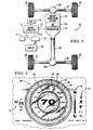
- FIGURE 1 is a plan view of a hybrid vehicle having a regenerative braking system usable in combination with the illuminable display of the present invention.
- FIGURE 2 is the illuminable display of the present invention.
- a schematic plan view of a hybrid vehicle 10 is shown, the vehicle 10 having a primary energy conversion system 24 that is driveably connectable with a rotatable output member 50, such as a driveshaft, of a transmission 18.
- the energy conversion system 24 is preferably an internal combustion engine, but may also be a fuel cell or other energy conversion system capable of generating sufficient torque for driving the rotatable output member 50 and axles 32 and/or 38 to thereby propel the vehicle 10.
- the transmission 18 is selectively connected to the energy conversion system 24 using a torque transfer mechanism 25, such as a friction clutch or hydrodynamic torque converter.
- a plurality of wheels 30 are operatively attached to a front axle 32 preferably having a front differential 52F, and/or to a rear axle 38 preferably having a rear differential 52R.
- the differentials 52F, 52R are of the type known in the art and configured to transmit torque from the output member 50 to either or both of the axles 32, 38, as required, and to distribute torque between opposing wheels 30 of each axle 32, 38 as required.
- Either or both of axles 32, 38 may be adapted to operate as drive axles suitable for powering the vehicle 10, depending on whether an all-wheel, frontwheel, or rear-wheel drive configuration is desired.
- the hybrid transmission 18 is connected to a motor/generator 17, which is operable as a secondary or regenerative braking energy conversion system.
- Motor/generator 17 is electrically connected to a rechargeable energy storage system or device 19, such as a nickel-metal hydride (Ni-MH) or other battery type, and/or an electrochemical capacitor having a relatively high energy density.
- a rechargeable energy storage system or device 19 such as a nickel-metal hydride (Ni-MH) or other battery type, and/or an electrochemical capacitor having a relatively high energy density.
- Energy in the form of electricity may be drawn from the energy storage device 19 to power the motor/generator 17 and transmission 18 when the motor/generator 17 is operating as a motor, and alternately transmitted to the energy storage device 19 and stored therein for later use when motor/generator 17 is acting as a generator.
- the vehicle 10 is configured to utilize the dual motor/generator capabilities of motor/generator 17 to achieve a regenerative braking capability of the type known in the art.
- the vehicle 10 may be slowed or stopped while simultaneously converting a substantial portion of the expended braking energy into useful electricity, and storing that electricity for later use within an energy storage system 19.
- the transfer of energy or recharging rate is a detectable quantity represented in Figure 1 as B R .
- vehicle 10 is shown as the preferred hybrid drive vehicle, those of ordinary skill in the art will appreciate that invention is also useable with a vehicle equipped with an alternate regenerative braking system, for example a vehicle that is adapted to recover hydraulic braking energy.
- a conventional friction braking system 37 such as a disk brake, is preferably positioned in proximity to each wheel 30 to provide an auxiliary or back-up mechanical braking capability for the regenerative braking system, or for primary use while the vehicle 10 is traveling at a relatively high rate of speed.
- a sensor 12 is preferably operatively attached to both the motor/generator 17 and to a brake input device 11, such as a brake pedal or actuator, and configured to detect, measure, calculate, or otherwise determine the amount of regenerative braking occurring at a given instant by using either or both of the detected braking level B i and/or the detected motor speed ⁇ m .
- the instantaneous amount of regenerative braking B R is transmitted or otherwise continuously communicated to a variably illuminable display 60 of the invention positioned within the passenger compartment of the vehicle 10, as discussed in more detail later hereinbelow.
- the variably illuminable display 60 includes a preferably circular gauge 62.
- Gauge 62 is shown as a speedometer having a moveable needle 63 and speed increments or hash marks arranged in an arch extending left to right, and a central display area 67 adapted to display the current vehicle speed in a digital format.
- a speedometer is shown in Figure 2
- the gauge 62 may alternately be presented to the driver using a heads up display or HUD separate from or in addition to the instrument display 60 to thereby allow the driver to view the information without averting attention from the road.
- a plurality of vehicle status indicators 70, 72, 74 are positioned in proximity to the gauge 62, preferably on either side of the gauge 62 in an aesthetically pleasing position and with indicators of similar function grouped together.
- the vehicle status indicators 70 are preferably commonly grouped and configured to provide vehicle status information such as the state or condition of the battery charge and/or low fuel levels.
- Vehicle status indicators 72 are preferably commonly grouped and configured to provide other information regarding vehicle status, such anti-lock braking system status and the presence of open doors.
- vehicle status indicators 74 are preferably commonly grouped and provide vehicle drive condition status, i.e. the current drive state of the transmission 18.
- the gauge 62 is substantially circumscribed or encircled by a lightable/illuminable portion or halo 66 having an inner diameter 80 and an outer diameter 82, with halo 66 having a plurality of variable appearance features, as described later hereinbelow.
- the inner and outer diameters 80, 82 respectively form or delimit a variable breadth or width 68.
- the location of the inner diameter 80 is preferably fixed and coextensive with gauge 62 as shown in Figure 2, and the position of the outer diameter 82 is preferably variably repositionable in response to the recharge rate B R (see Figure 1) provided by the regenerative braking process.
- variable width 68 of display 60 is variably illuminable in response to the instantaneous energy transfer or recharging rate B R (see Figure 1) provided by the regenerative braking process.
- Variable width 68 is illuminable in a vivid and aesthetically pleasing color, such as blue, although other colors, shades, and/or combinations of colors or shades may be equally suitable for use with the invention.
- variable appearance features of halo 66 include intensity, shade, and/or color, which alternately increase and decrease proportionately in response to the recharging rate B R .
- the illuminable halo 66 is minimized, transparent, or otherwise rendered substantially or totally invisible to the driver while the vehicle 10 is at a stand still, or the rate of regenerative braking B R is otherwise zero.
- the intensity of halo 66 then gradually increases proportionately in response to the recharging rate B R occurring relative to the onboard energy storage device 19 (see Figure 1) due to the regenerative braking process.
- the intensity of the halo 66 is gradually reduced or diminished until the halo 66 is once again rendered substantially or totally invisible to the driver.
- variable appearance features further include variable width 68 of halo 66, with the variable width 68 alternately expanding and contracting proportionately in response to the recharging rate B R occurring within the regenerative braking system of vehicle 10.
- the variable width 68 is minimized or otherwise rendered substantially or totally undetectable to the driver while the vehicle 10 is at a stand still, or when the rate of regenerative braking B R is otherwise zero.
- the variable width 68 then gradually increases proportionately in response to the recharging rate B R occurring relative to the onboard energy storage device 19 (see Figure 1) due to the regenerative braking process.
- the variable width 68 is gradually reduced or diminished until the halo 66 is once again rendered substantially or totally undetectable to the driver.
- the halo 66 provides an additional measure of safety by not requiring the driver to look away from the road in order to quickly determine the regenerative braking status, as the halo 66 would be peripherally visible to the driver.
Landscapes
- Engineering & Computer Science (AREA)
- Chemical & Material Sciences (AREA)
- Combustion & Propulsion (AREA)
- Transportation (AREA)
- Mechanical Engineering (AREA)
- Electric Propulsion And Braking For Vehicles (AREA)
- Control Of Indicators Other Than Cathode Ray Tubes (AREA)
Abstract
Description
- This application claims the benefit of
United States Provisional Application No. 60/805,892, filed June 27, 2006 - This invention relates generally to an illuminable display for use with a vehicle having a regenerative braking system, and in particular to a continuously variable illuminable display.
- Hybrid drive vehicles utilize multiple sources of energy in order to improve fuel efficiency and economy while reducing vehicle emissions, and typically include a rechargeable energy storage device that is electrically connected to at least one of the multiple energy sources. The multiple energy sources often include an internal combustion engine and at least one motor/generator, and the rechargeable energy storage device is usually a battery or battery pack having a high energy density. Other hybrid drive vehicles may alternately employ a fuel cell or other power source in place of the internal combustion engine in order to further reduce vehicle emissions.
- In a conventional or single power source vehicle, an alternator is typically used to convert mechanical energy from the fuel consumed in the internal combustion engine into electrical energy. The electrical energy is then used to continually recharge a single battery. During braking of such a conventional vehicle, the energy expended during braking is largely wasted. However, unlike such conventional vehicles, hybrid vehicles and certain other vehicles are able capture or harness a substantial amount of this otherwise wasted braking energy in a process commonly referred to as regenerative braking, thereby achieving a significant portion of their enhanced fuel economy.
- During regenerative braking aboard a hybrid vehicle, an electric motor operates in reverse rotational direction to thereby slow the vehicle and, in the process, to generate useful electricity that can recharge the onboard energy storage device or battery. On certain production hybrid vehicles, the status of this regenerative braking process is communicated to the driver and passengers through various static or animated displays positioned on a center display, or through a power flow meter located on an instrument cluster. In either case, the driver benefits from the experience of "seeing" free energy being usefully recycled for other beneficial uses aboard the vehicle. However, typical vehicle display methods and devices are often not designed in such a way as to elicit a satisfying emotional response commensurate with the positive feelings drivers of hybrid vehicles often have in driving their fuel efficient vehicles, and may require averting attention from the road in order to fully appreciate the magnitude of energy transfer.
- Accordingly, an improved vehicle display is provided. The display is positioned with respect to an instrument gauge or a heads up display and has a variable appearance. The display is electrically connectable to the vehicle such that the variation in appearance of the display is responsive to, and thus indicative of, the rate of energy transfer or recharging rate provided by the vehicle's regenerative braking process. The status of the regenerative process is thereby instantly and continuously communicated in an emotional and direct manner without requiring the driver to avert attention from the roadway.
- In one aspect of the invention, the display is an illuminable halo at least partially circumscribing an instrument gauge. The halo is minimized or preferably invisible while the vehicle is at a standstill and/or the rate of regenerative braking is otherwise zero, and has a variable width, variable intensity, and/or color that are proportionately and continuously variable in response to a detected battery recharging rate provided by the regenerative braking process.
- In another aspect of the invention, a vehicle is provided including a motor/generator adapted to provide regenerative braking, an energy storage device, a detectable energy transfer rate corresponding to the rate of transfer between the motor/generator and energy storage device, an illuminable display, and a sensor configured to detect and transmit the detectable rate to the illuminable display, which has a variable width, intensity, and/or color that is proportionately variable in response to the detectable rate.
- A method is also provided for displaying the rate of energy transfer between an energy storage device and a regenerative braking system aboard a vehicle, the method including detecting and communicating the rate to a variably illuminable display and sufficiently varying at least one of the width, color, and intensity of the display in response to the detected recharging rate provided by the regenerative braking.
- The above objects, features and advantages, and other objects, features and advantages of the present invention are readily apparent from the following detailed description of the best mode for carrying out the invention when taken in connection with the accompanying drawings.
- FIGURE 1 is a plan view of a hybrid vehicle having a regenerative braking system usable in combination with the illuminable display of the present invention; and
- FIGURE 2 is the illuminable display of the present invention.
- Referring to Figure 1, a schematic plan view of a
hybrid vehicle 10 is shown, thevehicle 10 having a primaryenergy conversion system 24 that is driveably connectable with arotatable output member 50, such as a driveshaft, of atransmission 18. Theenergy conversion system 24 is preferably an internal combustion engine, but may also be a fuel cell or other energy conversion system capable of generating sufficient torque for driving therotatable output member 50 andaxles 32 and/or 38 to thereby propel thevehicle 10. - The
transmission 18 is selectively connected to theenergy conversion system 24 using atorque transfer mechanism 25, such as a friction clutch or hydrodynamic torque converter. A plurality ofwheels 30 are operatively attached to afront axle 32 preferably having a front differential 52F, and/or to arear axle 38 preferably having arear differential 52R. Thedifferentials output member 50 to either or both of theaxles opposing wheels 30 of eachaxle axles vehicle 10, depending on whether an all-wheel, frontwheel, or rear-wheel drive configuration is desired. - The
hybrid transmission 18 is connected to a motor/generator 17, which is operable as a secondary or regenerative braking energy conversion system. Motor/generator 17 is electrically connected to a rechargeable energy storage system ordevice 19, such as a nickel-metal hydride (Ni-MH) or other battery type, and/or an electrochemical capacitor having a relatively high energy density. Energy in the form of electricity may be drawn from theenergy storage device 19 to power the motor/generator 17 andtransmission 18 when the motor/generator 17 is operating as a motor, and alternately transmitted to theenergy storage device 19 and stored therein for later use when motor/generator 17 is acting as a generator. - The
vehicle 10 is configured to utilize the dual motor/generator capabilities of motor/generator 17 to achieve a regenerative braking capability of the type known in the art. In general, by reversing the rotational direction of motor/generator 17, thevehicle 10 may be slowed or stopped while simultaneously converting a substantial portion of the expended braking energy into useful electricity, and storing that electricity for later use within anenergy storage system 19. The transfer of energy or recharging rate is a detectable quantity represented in Figure 1 as BR. Whilevehicle 10 is shown as the preferred hybrid drive vehicle, those of ordinary skill in the art will appreciate that invention is also useable with a vehicle equipped with an alternate regenerative braking system, for example a vehicle that is adapted to recover hydraulic braking energy. - A conventional
friction braking system 37, such as a disk brake, is preferably positioned in proximity to eachwheel 30 to provide an auxiliary or back-up mechanical braking capability for the regenerative braking system, or for primary use while thevehicle 10 is traveling at a relatively high rate of speed. Asensor 12 is preferably operatively attached to both the motor/generator 17 and to abrake input device 11, such as a brake pedal or actuator, and configured to detect, measure, calculate, or otherwise determine the amount of regenerative braking occurring at a given instant by using either or both of the detected braking level Bi and/or the detected motor speed ωm. The instantaneous amount of regenerative braking BR is transmitted or otherwise continuously communicated to a variablyilluminable display 60 of the invention positioned within the passenger compartment of thevehicle 10, as discussed in more detail later hereinbelow. - Turning to Figure 2, the variably
illuminable display 60 includes a preferablycircular gauge 62. Gauge 62 is shown as a speedometer having amoveable needle 63 and speed increments or hash marks arranged in an arch extending left to right, and a central display area 67 adapted to display the current vehicle speed in a digital format. Although a speedometer is shown in Figure 2, those of ordinary skill in the art will understand that other gauges, such tachometers, braking level gauges, fuel gauges, or other such gauges are also useable within the scope of the invention. Also, thegauge 62 may alternately be presented to the driver using a heads up display or HUD separate from or in addition to theinstrument display 60 to thereby allow the driver to view the information without averting attention from the road. - A plurality of
vehicle status indicators gauge 62, preferably on either side of thegauge 62 in an aesthetically pleasing position and with indicators of similar function grouped together. For example, as shown in Figure 2 thevehicle status indicators 70 are preferably commonly grouped and configured to provide vehicle status information such as the state or condition of the battery charge and/or low fuel levels.Vehicle status indicators 72 are preferably commonly grouped and configured to provide other information regarding vehicle status, such anti-lock braking system status and the presence of open doors. Finally,vehicle status indicators 74 are preferably commonly grouped and provide vehicle drive condition status, i.e. the current drive state of thetransmission 18. - In accordance with the invention, the
gauge 62 is substantially circumscribed or encircled by a lightable/illuminable portion orhalo 66 having aninner diameter 80 and anouter diameter 82, withhalo 66 having a plurality of variable appearance features, as described later hereinbelow. The inner andouter diameters width 68. The location of theinner diameter 80 is preferably fixed and coextensive withgauge 62 as shown in Figure 2, and the position of theouter diameter 82 is preferably variably repositionable in response to the recharge rate BR (see Figure 1) provided by the regenerative braking process. - In accordance with the invention, the
variable width 68 ofdisplay 60 is variably illuminable in response to the instantaneous energy transfer or recharging rate BR (see Figure 1) provided by the regenerative braking process.Variable width 68 is illuminable in a vivid and aesthetically pleasing color, such as blue, although other colors, shades, and/or combinations of colors or shades may be equally suitable for use with the invention. - In one embodiment, variable appearance features of
halo 66 include intensity, shade, and/or color, which alternately increase and decrease proportionately in response to the recharging rate BR. Theilluminable halo 66 is minimized, transparent, or otherwise rendered substantially or totally invisible to the driver while thevehicle 10 is at a stand still, or the rate of regenerative braking BR is otherwise zero. The intensity ofhalo 66 then gradually increases proportionately in response to the recharging rate BR occurring relative to the onboard energy storage device 19 (see Figure 1) due to the regenerative braking process. Likewise, as the rate of energy transfer decreases, the intensity of thehalo 66 is gradually reduced or diminished until thehalo 66 is once again rendered substantially or totally invisible to the driver. - In another embodiment, the variable appearance features further include
variable width 68 ofhalo 66, with thevariable width 68 alternately expanding and contracting proportionately in response to the recharging rate BR occurring within the regenerative braking system ofvehicle 10. Thevariable width 68 is minimized or otherwise rendered substantially or totally undetectable to the driver while thevehicle 10 is at a stand still, or when the rate of regenerative braking BR is otherwise zero. Thevariable width 68 then gradually increases proportionately in response to the recharging rate BR occurring relative to the onboard energy storage device 19 (see Figure 1) due to the regenerative braking process. Likewise, as the rate of energy transfer or recharging rate BR decreases, thevariable width 68 is gradually reduced or diminished until thehalo 66 is once again rendered substantially or totally undetectable to the driver. - By varying the intensity and/or
variable width 68 of thehalo 66 in this manner, an aesthetically pleasing and emotionally satisfying quality of feedback and awareness is provided to the driver of the vehicle. Additionally, thehalo 66 provides an additional measure of safety by not requiring the driver to look away from the road in order to quickly determine the regenerative braking status, as thehalo 66 would be peripherally visible to the driver. - While the best modes for carrying out the invention have been described in detail, those familiar with the art to which this invention relates will recognize various alternative designs and embodiments for practicing the invention within the scope of the appended claims.
Claims (13)
- A variably illuminable display for use with a vehicle having a regenerative braking energy conversion system with an energy storage device and a detectable recharging rate, said display having at least one variable appearance feature that is controllably variable in proportionate response to said recharging rate.
- The display of claim 1, wherein said at least one variable appearance feature is selected from the group of variable width, variable intensity, and variable color.
- The display of claim 1, wherein said illuminable display is adapted to at least partially circumscribe an instrument gauge.
- The display of claim 1, wherein said illuminable display comprises a halo substantially circumscribing an instrument gauge, and wherein said instrument gauge is a speedometer.
- The display of claim t, wherein said display includes an illuminable halo substantially circumscribing an instrument gauge and having a variable width and variable intensity, wherein said display is adapted to elicit a positive emotional response by continuously varying at least one of said variable intensity and said variable width in proportionate response to said recharging rate.
- A vehicle comprising:an energy storage device;a motor/generator adapted to provide regenerative braking of said vehicle and having a detectable energy transfer rate corresponding to the rate of transfer between said motor/generator and said energy storage device;a variably illuminable display at least partially circumscribing an instrument gauge, thereby forming a halo around said instrument gauge; andat least one sensor configured to detect said detectable rate and transmit said detectable rate to said variably illuminable display;wherein said halo of said variably illuminable display has at least one variable appearance feature that is in proportion to said detected rate.
- The vehicle of claim 6, wherein said halo substantially circumscribes said instrument gauge.
- The vehicle of claim 6 or 7, wherein said instrument gauge is a speedometer having a center display area configured to display the speed of said vehicle in a digital format.
- The vehicle of claim 6, 7 or 8, wherein said at least one variable feature is selected from the group of variable width, variable intensity, and variable color.
- A method of displaying a detected rate of energy transfer between an energy storage device and a regenerative braking system aboard a vehicle, the method comprising detecting and communicating said rate to a variably illuminable display and sufficiently varying at least one of the width, color, and intensity of said display in proportionate response to said detected rate, whereby to improve the awareness of said detected rate.
- The method of claim 10, wherein said controllable display is a circular halo at least partially encircling an instrument gauge.
- The method of claim 10 or 11, wherein said instrument gauge is a speedometer.
- The method of claim 10, 11 or 12, wherein said at least one of said width, color, and intensity is proportionately variable in response to said detected rate.
Applications Claiming Priority (2)
| Application Number | Priority Date | Filing Date | Title |
|---|---|---|---|
| US80589206P | 2006-06-27 | 2006-06-27 | |
| US11/676,517 US7750796B2 (en) | 2006-06-27 | 2007-02-20 | Regenerative braking halo and method |
Publications (2)
| Publication Number | Publication Date |
|---|---|
| EP1872999A2 true EP1872999A2 (en) | 2008-01-02 |
| EP1872999A3 EP1872999A3 (en) | 2010-01-27 |
Family
ID=38529398
Family Applications (1)
| Application Number | Title | Priority Date | Filing Date |
|---|---|---|---|
| EP07011990A Withdrawn EP1872999A3 (en) | 2006-06-27 | 2007-06-19 | Regenerative braking display device and method |
Country Status (3)
| Country | Link |
|---|---|
| US (1) | US7750796B2 (en) |
| EP (1) | EP1872999A3 (en) |
| CN (1) | CN101097158B (en) |
Cited By (2)
| Publication number | Priority date | Publication date | Assignee | Title |
|---|---|---|---|---|
| US8855880B2 (en) | 2009-10-05 | 2014-10-07 | Toyota Motor Engineering & Manufacturing North America, Inc. | Method and system for displaying braking information |
| EP2661387A4 (en) * | 2011-01-06 | 2018-04-25 | Ford Global Technologies, LLC | Regenerative braking feedback display system and method |
Families Citing this family (15)
| Publication number | Priority date | Publication date | Assignee | Title |
|---|---|---|---|---|
| US20100083894A1 (en) * | 2008-10-07 | 2010-04-08 | Continental Automotive Systems Us, Inc. | Multi-colored features for instrument cluster gauges |
| US20100106353A1 (en) * | 2008-10-28 | 2010-04-29 | Ford Global Technologies, Llc | Regenerative braking and charge flow state indication system for a hybrid electric vehicle |
| JP2011024353A (en) * | 2009-07-16 | 2011-02-03 | Aisin Aw Co Ltd | Guidance device, guidance method, and guidance program |
| US8248221B2 (en) * | 2009-07-28 | 2012-08-21 | Ford Global Technologies, Llc | Method and system for displaying recovered energy for a hybrid electric vehicle |
| JP5212518B2 (en) * | 2011-06-03 | 2013-06-19 | トヨタ自動車株式会社 | Vehicle operating state display device |
| US8919100B2 (en) | 2011-06-06 | 2014-12-30 | GM Global Technology Operations LLC | Method of using a regenerative brake system for heating a motor vehicle catalytic converter and powering other electrical accessories |
| US9718359B2 (en) * | 2011-08-30 | 2017-08-01 | Ford Global Technologies, Llc | Braking display system and method |
| DE102013220426B3 (en) * | 2013-10-10 | 2015-03-19 | Continental Automotive Gmbh | Method for operating a vehicle and driver assistance system for a vehicle |
| US20160031369A1 (en) * | 2014-07-31 | 2016-02-04 | Continental Automotive Systems, Inc. | Color on demand system with color gradient |
| US20170050520A1 (en) * | 2015-08-18 | 2017-02-23 | Ford Global Technologies, Llc | Instrument indicator needle device providing visual indication of instantaneous fuel economy |
| US9671244B2 (en) | 2015-09-18 | 2017-06-06 | Les Solutions Cyclelabs Inc. | Electronic device and method for providing travel information |
| JP6631358B2 (en) * | 2016-03-28 | 2020-01-15 | 三菱自動車工業株式会社 | Regenerative energy display |
| JP7195879B2 (en) * | 2018-11-05 | 2022-12-26 | 京セラ株式会社 | Display device, 3D display device, head-up display and vehicle |
| CN112695673B (en) * | 2018-12-20 | 2021-12-07 | 余笑眉 | Municipal administration is used presumes device that width within range vehicle passes through |
| USD921506S1 (en) | 2019-04-26 | 2021-06-08 | SmartHalo Technologies Inc. | Electronic device for providing travel information |
Family Cites Families (31)
| Publication number | Priority date | Publication date | Assignee | Title |
|---|---|---|---|---|
| US1486379A (en) * | 1922-02-11 | 1924-03-11 | Motor Safety Indicator Inc | Speed-indicating signal |
| WO1987004556A1 (en) * | 1986-01-27 | 1987-07-30 | Autodisplay A/S | An arrangement in a display or instrument board |
| US5150098A (en) * | 1990-11-13 | 1992-09-22 | Robert Rakow | Brake signaling system and process |
| JPH06201407A (en) * | 1992-09-16 | 1994-07-19 | Caterpillar Inc | Method and apparatus for displaying sensor output in diagnostic system |
| DE19533829C1 (en) * | 1995-09-13 | 1996-09-19 | Daimler Benz Ag | Tractive power monitor for vehicles with electric or hybrid drive |
| KR100471551B1 (en) * | 1996-05-24 | 2005-04-14 | 히노지도샤코교 가부시기가이샤 | Control System for On-vehicle Batteries |
| US5815072A (en) * | 1996-07-10 | 1998-09-29 | Toyoda Gosei Co., Ltd. | Vehicle display device |
| SE510918C2 (en) * | 1997-08-11 | 1999-07-05 | Volvo Ab | displays Instruments |
| US6717376B2 (en) * | 1997-08-26 | 2004-04-06 | Color Kinetics, Incorporated | Automotive information systems |
| JP3716619B2 (en) * | 1998-05-14 | 2005-11-16 | 日産自動車株式会社 | Battery remaining capacity meter |
| JP3929646B2 (en) | 1999-07-15 | 2007-06-13 | 本田技研工業株式会社 | Hybrid vehicle shift position presentation device |
| US6333688B1 (en) * | 2000-03-17 | 2001-12-25 | Tyrone A. Brown | Tail light enhancement system |
| US6587043B1 (en) * | 2000-08-10 | 2003-07-01 | Meritor Heavy Vehicle Technology, Llc | Driver warning system |
| US6480106B1 (en) * | 2000-12-11 | 2002-11-12 | Ford Global Technologies, Inc. | Rate of consumption gauge with variable rate of consumption limits |
| SE518046C2 (en) * | 2000-12-28 | 2002-08-20 | Scania Cv Ab | Speedometer intended to indicate multiple speed values |
| JP3892236B2 (en) * | 2001-02-20 | 2007-03-14 | 本田技研工業株式会社 | Control device for hybrid vehicle |
| SE519083C2 (en) * | 2001-05-17 | 2003-01-07 | Scania Cv Ab | Speedometer for a vehicle |
| JP4097921B2 (en) * | 2001-09-18 | 2008-06-11 | 本田技研工業株式会社 | Display device for means of transportation |
| US6675650B1 (en) * | 2001-11-12 | 2004-01-13 | Yazaki North America | Automotive display |
| JP3853660B2 (en) * | 2002-01-23 | 2006-12-06 | 本田技研工業株式会社 | Display device for fuel cell vehicle |
| JP2004074871A (en) * | 2002-08-13 | 2004-03-11 | Kawasaki Heavy Ind Ltd | Display for vehicle |
| US7075423B2 (en) * | 2003-10-06 | 2006-07-11 | Joseph Edward Currie | Combination illuminating inverse function power indicator and a brake light |
| US7474309B2 (en) * | 2003-12-16 | 2009-01-06 | General Motors Corporation | Hybrid vehicle display apparatus and method |
| JP4568087B2 (en) * | 2004-01-28 | 2010-10-27 | 矢崎総業株式会社 | Vehicle display device |
| US7047120B2 (en) * | 2004-04-14 | 2006-05-16 | Ford Global Technologies, Llc | Vehicle and method for controlling brake system indicators |
| JP4443345B2 (en) * | 2004-08-19 | 2010-03-31 | 川崎重工業株式会社 | Small planing boat display device |
| US7439711B2 (en) * | 2004-09-27 | 2008-10-21 | Oshkosh Corporation | Energy storage device including a status indicator |
| JP4648681B2 (en) * | 2004-11-02 | 2011-03-09 | 矢崎総業株式会社 | Vehicle display device |
| US7248175B2 (en) * | 2005-02-04 | 2007-07-24 | Shih-Hsiung Wu | Synchronously lighting apparatus of vehicle meter |
| US7501939B1 (en) * | 2005-08-10 | 2009-03-10 | Yazaki North America, Inc. | Display device with dimmable segments |
| US7178479B1 (en) * | 2006-01-23 | 2007-02-20 | Milton Richter | Peripheral view speedometer |
-
2007
- 2007-02-20 US US11/676,517 patent/US7750796B2/en not_active Expired - Fee Related
- 2007-06-19 EP EP07011990A patent/EP1872999A3/en not_active Withdrawn
- 2007-06-27 CN CN2007101096980A patent/CN101097158B/en not_active Expired - Fee Related
Non-Patent Citations (1)
| Title |
|---|
| None |
Cited By (3)
| Publication number | Priority date | Publication date | Assignee | Title |
|---|---|---|---|---|
| US8855880B2 (en) | 2009-10-05 | 2014-10-07 | Toyota Motor Engineering & Manufacturing North America, Inc. | Method and system for displaying braking information |
| US9421962B2 (en) | 2009-10-05 | 2016-08-23 | Toyota Motor Engineering & Manufacturing North America, Inc. | Method and system for displaying braking information |
| EP2661387A4 (en) * | 2011-01-06 | 2018-04-25 | Ford Global Technologies, LLC | Regenerative braking feedback display system and method |
Also Published As
| Publication number | Publication date |
|---|---|
| EP1872999A3 (en) | 2010-01-27 |
| US7750796B2 (en) | 2010-07-06 |
| CN101097158B (en) | 2010-06-09 |
| CN101097158A (en) | 2008-01-02 |
| US20070295544A1 (en) | 2007-12-27 |
Similar Documents
| Publication | Publication Date | Title |
|---|---|---|
| US7750796B2 (en) | Regenerative braking halo and method | |
| US11054009B2 (en) | Single electric motor drive axle with multiple ratios | |
| EP1966019B1 (en) | Hybrid vehicle and control method thereof | |
| CN100391768C (en) | A multi-axle drive system for an oil-electric hybrid vehicle and a method for improving the turning radius of the vehicle by applying the system | |
| CN101985282B (en) | Displaying system for vehicle | |
| US8244420B2 (en) | Vehicle, vehicle control method, and drive unit | |
| US12330507B2 (en) | Auxiliary electrical traction motor for vehicles | |
| US9248741B2 (en) | Torque indicating device and vehicle including same | |
| US8596392B2 (en) | Method for operation of a hybrid vehicle | |
| CN101583526A (en) | Vehicle and its control method | |
| US10300910B2 (en) | Apparatus for driving rear-wheels of environment-friendly vehicle | |
| US8397850B2 (en) | System and method for driving hybrid electric vehicle | |
| US8275529B2 (en) | Apparatus and method for controlling a hybrid vehicle | |
| CN104163106A (en) | Control device for motor vehicle and application thereof in the motor vehicle | |
| JPH07315078A (en) | Display device for hybrid vehicle | |
| JPWO2012143989A1 (en) | Electric vehicle and control method thereof | |
| US10249111B2 (en) | Method and system for providing feedback to a driver of a hybrid or electric vehicle | |
| CN2925948Y (en) | Multi-bridge driving system of mixed-dynamic vehicle | |
| JP2011218871A (en) | Standby four-wheel drive vehicle | |
| JP2011223681A (en) | Controller of regenerative braking torque | |
| JP4094591B2 (en) | Drive device for hybrid vehicle | |
| CN101204919B (en) | Mixed motor vehicle drive system | |
| JP2005035413A (en) | Vehicle display device and vehicle | |
| EP2555937B1 (en) | Kit for transforming a conventional motor vehicle into a solar hybrid vehicle, and relevant motorvehicle obtained by the kit | |
| JP2009018708A (en) | Vehicle and control method thereof |
Legal Events
| Date | Code | Title | Description |
|---|---|---|---|
| PUAI | Public reference made under article 153(3) epc to a published international application that has entered the european phase |
Free format text: ORIGINAL CODE: 0009012 |
|
| AK | Designated contracting states |
Kind code of ref document: A2 Designated state(s): AT BE BG CH CY CZ DE DK EE ES FI FR GB GR HU IE IS IT LI LT LU LV MC MT NL PL PT RO SE SI SK TR |
|
| AX | Request for extension of the european patent |
Extension state: AL BA HR MK YU |
|
| PUAL | Search report despatched |
Free format text: ORIGINAL CODE: 0009013 |
|
| AK | Designated contracting states |
Kind code of ref document: A3 Designated state(s): AT BE BG CH CY CZ DE DK EE ES FI FR GB GR HU IE IS IT LI LT LU LV MC MT NL PL PT RO SE SI SK TR |
|
| AX | Request for extension of the european patent |
Extension state: AL BA HR MK RS |
|
| 17P | Request for examination filed |
Effective date: 20100224 |
|
| 17Q | First examination report despatched |
Effective date: 20100326 |
|
| AKX | Designation fees paid |
Designated state(s): DE |
|
| RAP1 | Party data changed (applicant data changed or rights of an application transferred) |
Owner name: GM GLOBAL TECHNOLOGY OPERATIONS LLC |
|
| STAA | Information on the status of an ep patent application or granted ep patent |
Free format text: STATUS: THE APPLICATION IS DEEMED TO BE WITHDRAWN |
|
| 18D | Application deemed to be withdrawn |
Effective date: 20130115 |