JP4097921B2 - Display device for means of transportation - Google Patents
Display device for means of transportation Download PDFInfo
- Publication number
- JP4097921B2 JP4097921B2 JP2001283563A JP2001283563A JP4097921B2 JP 4097921 B2 JP4097921 B2 JP 4097921B2 JP 2001283563 A JP2001283563 A JP 2001283563A JP 2001283563 A JP2001283563 A JP 2001283563A JP 4097921 B2 JP4097921 B2 JP 4097921B2
- Authority
- JP
- Japan
- Prior art keywords
- switch
- display
- display device
- control unit
- engine
- Prior art date
- Legal status (The legal status is an assumption and is not a legal conclusion. Google has not performed a legal analysis and makes no representation as to the accuracy of the status listed.)
- Expired - Fee Related
Links
- 239000000446 fuel Substances 0.000 claims description 71
- 238000002347 injection Methods 0.000 claims description 42
- 239000007924 injection Substances 0.000 claims description 42
- 230000005856 abnormality Effects 0.000 claims description 25
- 230000004397 blinking Effects 0.000 claims description 21
- 208000024891 symptom Diseases 0.000 claims description 12
- 238000003745 diagnosis Methods 0.000 claims description 9
- 230000002159 abnormal effect Effects 0.000 description 16
- 238000000034 method Methods 0.000 description 16
- XLYOFNOQVPJJNP-UHFFFAOYSA-N water Substances O XLYOFNOQVPJJNP-UHFFFAOYSA-N 0.000 description 12
- 238000003825 pressing Methods 0.000 description 10
- 238000010586 diagram Methods 0.000 description 9
- 239000004973 liquid crystal related substance Substances 0.000 description 9
- 239000000203 mixture Substances 0.000 description 7
- 239000007858 starting material Substances 0.000 description 7
- 230000002265 prevention Effects 0.000 description 5
- 239000002828 fuel tank Substances 0.000 description 4
- 230000007246 mechanism Effects 0.000 description 4
- 239000010705 motor oil Substances 0.000 description 4
- 238000001514 detection method Methods 0.000 description 3
- 239000003921 oil Substances 0.000 description 3
- 230000008569 process Effects 0.000 description 3
- 238000013024 troubleshooting Methods 0.000 description 3
- 230000009471 action Effects 0.000 description 2
- 230000000694 effects Effects 0.000 description 2
- 241000238413 Octopus Species 0.000 description 1
- 239000000498 cooling water Substances 0.000 description 1
- 230000010485 coping Effects 0.000 description 1
- 238000007689 inspection Methods 0.000 description 1
- 238000004519 manufacturing process Methods 0.000 description 1
- 238000012856 packing Methods 0.000 description 1
- 230000008439 repair process Effects 0.000 description 1
- 230000004044 response Effects 0.000 description 1
- 238000005549 size reduction Methods 0.000 description 1
- 230000001360 synchronised effect Effects 0.000 description 1
Images


Classifications
-
- F—MECHANICAL ENGINEERING; LIGHTING; HEATING; WEAPONS; BLASTING
- F02—COMBUSTION ENGINES; HOT-GAS OR COMBUSTION-PRODUCT ENGINE PLANTS
- F02B—INTERNAL-COMBUSTION PISTON ENGINES; COMBUSTION ENGINES IN GENERAL
- F02B61/00—Adaptations of engines for driving vehicles or for driving propellers; Combinations of engines with gearing
- F02B61/04—Adaptations of engines for driving vehicles or for driving propellers; Combinations of engines with gearing for driving propellers
- F02B61/045—Adaptations of engines for driving vehicles or for driving propellers; Combinations of engines with gearing for driving propellers for outboard marine engines
-
- F—MECHANICAL ENGINEERING; LIGHTING; HEATING; WEAPONS; BLASTING
- F02—COMBUSTION ENGINES; HOT-GAS OR COMBUSTION-PRODUCT ENGINE PLANTS
- F02D—CONTROLLING COMBUSTION ENGINES
- F02D41/00—Electrical control of supply of combustible mixture or its constituents
- F02D41/22—Safety or indicating devices for abnormal conditions
- F02D2041/228—Warning displays
-
- F—MECHANICAL ENGINEERING; LIGHTING; HEATING; WEAPONS; BLASTING
- F02—COMBUSTION ENGINES; HOT-GAS OR COMBUSTION-PRODUCT ENGINE PLANTS
- F02D—CONTROLLING COMBUSTION ENGINES
- F02D2200/00—Input parameters for engine control
- F02D2200/02—Input parameters for engine control the parameters being related to the engine
- F02D2200/023—Temperature of lubricating oil or working fluid
-
- F—MECHANICAL ENGINEERING; LIGHTING; HEATING; WEAPONS; BLASTING
- F02—COMBUSTION ENGINES; HOT-GAS OR COMBUSTION-PRODUCT ENGINE PLANTS
- F02D—CONTROLLING COMBUSTION ENGINES
- F02D2200/00—Input parameters for engine control
- F02D2200/02—Input parameters for engine control the parameters being related to the engine
- F02D2200/06—Fuel or fuel supply system parameters
- F02D2200/0602—Fuel pressure
-
- F—MECHANICAL ENGINEERING; LIGHTING; HEATING; WEAPONS; BLASTING
- F02—COMBUSTION ENGINES; HOT-GAS OR COMBUSTION-PRODUCT ENGINE PLANTS
- F02D—CONTROLLING COMBUSTION ENGINES
- F02D41/00—Electrical control of supply of combustible mixture or its constituents
- F02D41/02—Circuit arrangements for generating control signals
- F02D41/14—Introducing closed-loop corrections
- F02D41/1438—Introducing closed-loop corrections using means for determining characteristics of the combustion gases; Sensors therefor
- F02D41/1444—Introducing closed-loop corrections using means for determining characteristics of the combustion gases; Sensors therefor characterised by the characteristics of the combustion gases
- F02D41/1446—Introducing closed-loop corrections using means for determining characteristics of the combustion gases; Sensors therefor characterised by the characteristics of the combustion gases the characteristics being exhaust temperatures
-
- F—MECHANICAL ENGINEERING; LIGHTING; HEATING; WEAPONS; BLASTING
- F02—COMBUSTION ENGINES; HOT-GAS OR COMBUSTION-PRODUCT ENGINE PLANTS
- F02D—CONTROLLING COMBUSTION ENGINES
- F02D41/00—Electrical control of supply of combustible mixture or its constituents
- F02D41/22—Safety or indicating devices for abnormal conditions
- F02D41/221—Safety or indicating devices for abnormal conditions relating to the failure of actuators or electrically driven elements
Landscapes
- Engineering & Computer Science (AREA)
- Ocean & Marine Engineering (AREA)
- Chemical & Material Sciences (AREA)
- Combustion & Propulsion (AREA)
- Mechanical Engineering (AREA)
- General Engineering & Computer Science (AREA)
- Instrument Panels (AREA)
- Combined Controls Of Internal Combustion Engines (AREA)
- Control Of Vehicle Engines Or Engines For Specific Uses (AREA)
- Electrical Control Of Air Or Fuel Supplied To Internal-Combustion Engine (AREA)
Description
【0001】
【発明の属する技術分野】
本発明は、駆動源に燃料を噴射する燃料噴射装置を有する運輸手段の表示装置に関する。なお、運輸手段とは、船舶、航空機、鉄道又は車両などを含む運輸全般的な手段を言う。
【0002】
【従来の技術】
運輸手段の表示装置として、例えば特開平9−169298号公報「小型船舶の始動装置」が知られている。
上記技術は、同公報の図2及び図3によれば、ゲージパネル6に制御手段Eをを設け、ゲージパネル6に速度計や回転計などのメータ61を設け、ストップウォッチや航走時間などを表示する表示部620を設け、ゲージパネル6にオン・オフスイッチ66を介して電源を接続するとともにリレー67を介してスタータモータ68を接続し、暗証番号を入力することでスタータモータ68を回転させエンジン5を始動する操作手段62をゲージパネル6に設け、表示部620を切換えるモード切換えボタン610をゲージパネル6に設けたものである。
【0003】
【発明が解決しようとする課題】
小型船舶の始動装置では、メータ61で艇速を表示し、表示部620で航走時間などを表示できる。また、モード切換えボタン610で表示部620を切換えたり、操作手段62で暗証番号などを入力することもできる。これらの表示機能や操作機能を利用して補機類などの異常などを警告できるとともに異常の症状までを判別できるとすれば便利である。
すなわち、運輸手段の運行状況のみならず運輸手段の異常を警告するとともに異常の症状までを判別できる表示装置が望まれる。
【0004】
そこで、本発明の目的は、運輸手段の運行状況のみならず運輸手段の異常を表示するとともに異常の症状までを判別できる表示装置を提供することにある。
【0005】
【課題を解決するための手段】
上記目的を達成するために請求項1の運輸手段の表示装置は、運転情報や各種警告を表示する多機能表示部と、この多機能表示部の表示内容を操作する操作スイッチと、駆動源に燃料を噴射する燃料噴射装置と、を備えた運輸手段において、多機能表示部に、燃料噴射装置に異常が生じたことを警告する警告灯を設け、この警告灯を点灯若しくは点滅させるようにするとともに、この警告灯が点灯若しくは点滅したときに操作スイッチを操作することで異常の症状を点滅パターンにて表示する機能を備え、操作スイッチに、時刻などを設定するときに使用するセットスイッチと、切換え表示部の切換えを設定するときに使用するモードスイッチとが設けられ、セットスイッチを長押ししたときに、エンジンの出力を低く制限する制限運転とエンジンの出力を制限しない通常運転とを切換えるとともに、セットスイッチとモードスイッチとを同時に長押ししたときに、故障診断を行うようにしたことを特徴とする。
【0006】
一般的に、燃料噴射装置は空気と燃料とを混合し気化させた混合気をエンジンに送る装置であり、例えば、燃料噴射装置に異常が発生した場合には、吸気系統の異常なのか、燃料供給系統の異常なのか又はこれら以外の異常なのか判別するのが困難である。
【0007】
そこで、燃料噴射装置に異常が生じたことを警告する警告灯を設け、燃料噴射装置の異常を知らせる。また、この警告灯を点灯若しくは点滅させるようにすることで、燃料噴射装置の異常であることを強調する。さらに、警告灯が点灯若しくは点滅したときに操作スイッチを操作することで異常の症状を点滅パターンにて表示する機能を備えることで、燃料噴射装置のトラブルに対して迅速な処置をする。
すなわち、警告灯が点灯若しくは点滅したときに操作スイッチを操作することで異常の症状を点滅パターンにて表示する機能を備え、操作スイッチに、時刻などを設定するときに使用するセットスイッチと、切換え表示部の切換えを設定するときに使用するモードスイッチとが設けられ、セットスイッチを長押ししたときに、エンジンの出力を低く制限する制限運転とエンジンの出力を制限しない通常運転とを切換えるとともに、セットスイッチとモードスイッチとを同時に長押ししたときに、故障診断を行うようにすることで、燃料噴射装置のトラブル解決の利便性の向上を図る。
請求項2は、セットスイッチ及びモードスイッチの下方に、IDナンバを打込み決定するときに使用するIDセットスイッチと、IDナンバを入力するIDナンバスイッチとが設けられたことを特徴とする。
【0008】
【発明の実施の形態】
本発明の実施の形態を添付図に基づいて以下に説明する。なお、図面は符号の向きに見るものとする。
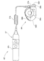
図1は本発明に係る表示装置を搭載した運輸手段の側面図であり、本発明に係る運輸手段としてのジェット推進艇10は、艇体11の前部11aに取付けた燃料タンク14と、この燃料タンク14の後方に設けたエンジン15と、このエンジン15の後方に設けたポンプ室16と、このポンプ室16に設けたジェット推進機17と、エンジン15に吸気側を取付けるとともに排気側をポンプ室16に取付けた排気ユニット18と、燃料タンク14の上方に取付けたステアリング28と、このステアリング28の後方に取付けたシート29とからなる。
【0009】
ジェット推進機17は、艇底12の開口13から後方へ延びたハウジング21を有し、このハウジング21内にインペラ22を回転自在に取り付け、インペラ22をエンジン15の駆動軸23に連結したものである。
ジェット推進機17によれば、エンジン15を駆動してインペラ22を回転させることにより、艇底12の開口13から吸引した水をハウジング21の後端開口を介してノズルとしての操舵管25から艇体11の後方へ噴射することができる。
【0010】
操舵管25は、ハウジング21の後端に左右方向にスイング自在に取付けた部材であり、ステアリング28の操作で左右方向にスイングすることにより艇体11の操舵方向をコントロールする操舵用のノズルである。
【0011】
このジェット推進艇10によれば、燃料タンク14からエンジン15に燃料を供給してエンジン15を駆動し、このエンジン15の駆動力を駆動軸23を介してインペラ22に伝え、インペラ22を回転することにより艇底12の開口13から水を吸引し、吸引した水をハウジング21の後端を通して操舵管25から噴射して推進することができる。
また、後述するように、ジェット推進艇10は、ジェット水流の量又はジェット水流の噴射できる時間を精度よく制御するために制御部を備えた船艇である。さらに、エンジン出力を所定の出力を超えないように制限する制限運転モードに切換えできる船艇でもある。
【0012】
図中、26は艇艇をバックさせるときに操舵管25に被せてジェット水流を前方斜め下方に流すためのリバースバケット、33はリバースバケット26を操作する操作ノブ、34はエキゾーストパイプ、35はエキゾーストボディ、27は艇体11の電源であるバッテリ、36はウォータマフラ、37はウォータロックパイプ、38はテールパイプ、39はレゾネータ、45はランヤードスイッチ付きメインスイッチを示す。
【0013】
図2は本発明に係る表示装置を搭載した運輸手段の平面図であり、ステアリング28は、艇体に回転自在に取付けるステアリングシャフト41と、このステアリングシャフト41の上端に取付けるハンドルバー43と、このハンドルバー43の左右端部に取付けた左右のハンドルグリップ44L,44Rと、左のハンドルグリップ44Lの根元に設けたランヤードスイッチ付きメインスイッチ45と、右のハンドルグリップ44Rの根元にスイング自在に取付けたスロットルレバー46と、このスロットルレバー46からスッロトルに延ばしたスロットルケーブル47と、このステアリングシャフト41の下端に設けた転舵検出機構48と、からなる。
【0014】
図3は本発明に係る表示装置を搭載した運輸手段の転舵機構の平面図であり、転舵検出機構48は、艇体11(図1参照)に取付けたブラケット51と、ステアリングシャフト41の下端に取付けたスイッチカム52と、このスイッチカム52でON/OFFする転舵スイッチ53と、ステアリングシャフト41の下端に取付けたカムプレート54とからなる。なお、55は、カムプレート54の端部に回転自在に取付けることで操舵管25(図1参照)を駆動する駆動リンク、53aは転舵スイッチ53のスイッチレバー、53bは転舵スイッチ53の本体部を示す。
【0015】
図4は本発明に係る表示装置を搭載した運輸手段のOTS制御装置のブロック図である。ここで、OTSとは Off Throttle Steering System の略であり、スロットル64を戻したときでも所定のジェット水流を少しの間維持できるようにする装置である。
ジェット推進艇のOTS制御装置60は、艇体11(図1参照)の操舵をする前記ステアリング28と、エンジン15(図1参照)に燃料を供給する燃料噴射装置61と、艇体11を制御する制御部(ECU)101と、艇体11の状況を表示するコントロールユニットとしての表示制御部74を備えた表示装置70と、から構成するシステムであり、所定回転数以上で所定時間以上エンジン15が回転し、且つ所定開度以上で所定時間以上スロットル64が開いることを条件として、スロットル64を閉じるとともにステアリング28を所定角度以上に左又は右に切ったときに、スロットル64に関係なくエンジン15の回転数を予め定めた回転数に上げるためのシステムである。
【0016】
燃料噴射装置61は、制御部(ECU)101からの情報で負圧を制御するソレノイド62と、吸気通路63に設けることでエンジン15(図1参照)に供給する混合気の量を調整するスロットル64と、これらのソレノイド62及びスロットル64の間に設けることでスロットル開度を調整するダイヤフラム65と、スロットル開度を検出するスロットルセンサ66と、ソレノイド62及び吸気通路63の間に設けることで負圧の逆流防止及び加圧の侵入防止をするワンウェイバルブ67と、このワンウェイバルブ67及びソレノイド62の間に設けることで負圧変動を緩和するサージタンク68と、燃料を細かい噴霧状にして吸気通路63に供給するインジェクタ69、とから構成する。図中、θはスロットル開度を示す。
【0017】
図5は図1の5矢視図であり、ジェット推進艇の表示装置70(以下、表示装置70」と略記する)の正面を示す。
表示装置70は、運転情報を表示する液晶表示部としての液晶ディバイス71と、各種警告の必要なときに点灯又は点滅させる警告灯72と、切換え操作や入力操作をする操作スイッチ73と、液晶ディバイス71及び警告灯72を駆動するとともに艇体11を制御する表示制御部74と、これらの液晶ディバイス71、警告灯72及び表示制御部74を一括して覆うハウジング75と、警告灯72を点灯又は点滅させるときに警告音を発するブザー79とからなる。
【0018】
液晶ディバイス71は、エンジン15(図1参照)の回転数を表示するタコメータ76と、艇速を表示するスピードメータ77と、運転情報や各種警告を表示する多機能表示部78と、を形成したものである。
【0019】
多機能表示部78は、バッテリ27(図1参照)が所定の電圧を下回ったときに点滅させる充電マーク78aと、冷却水の温度が所定の温度を超えた時に点滅させる水温警告マーク78bと、エンジンオイルの量が所定の量を下回ったとき若しくはエンジンオイルの圧力が所定値以下になった時に点滅させるオイル警告マーク78cと、燃料噴射装置61(図3参照)に異常が発生したときに点滅させる燃料噴射装置警告マーク78d(以下[FI警告マーク78d」と略記する)と、エンジン出力を所定の出力を超えないように制限する制限運転モードに設定したことを表示する表示灯としてのリミットモード表示マーク78eと、燃料の残量を表示する残量表示計78fと、燃料の残量が少ないときに給油を促す給油警告マーク78gと、盗難防止のための暗証番号としてのID(Identification)ナンバーがセットされ施錠されているときに点滅させるIDナンバマーク78hと、盗難防止機能を解除したときに点灯させるキーマーク78iと、時刻表示、航行時間表示、エンジン回転数(以下「Neタコ表示」と略記する)、航行距離表示、若しくは積算航行時間表示に切換えて表示する切換え表示部78jと、から構成する。
【0020】
すなわち、ジェット推進艇10(図1参照)は、IDナンバを入力することで電源をON若しくはOFFすることのできる盗難防止機能を備えた推進艇でもある。
【0021】
操作スイッチ73は、時刻などを設定するときに使用するセットスイッチ73aと、切換え表示部の切換えや前記制限運転モードを設定するときに使用するモードスイッチ73bと、IDナンバを打込み決定するときに使用するIDセットスイッチ73c及びIDナンバスイッチ73dと、からなる。
【0022】
図6は本発明に係る表示装置を搭載した運輸手段の表示装置の平面断面図であり、ハウジング75は、表示制御部74を取付けるロアケース81と、このロアケース81にパッキン82を介して取付けたアッパケース83と、このアッパケース83の開口83aに取付けた表示窓84と、ロアケース81の底81aから束ねたハーネス85を引出すために設けたブッシュ86と、からなる。
81bはロアケース81に立てることで表示制御部74を支持するボス、81cはロアケース81に立てることで表示制御部74を止める止めボス、87a,87bは表示制御部74に接続したコネクタ、88a,88bは表示制御部74から延出した複数のハーネスである。
【0023】
図7は本発明に係る表示装置を搭載した運輸手段の電源システムのブロック図であり、電源システム90は、バッテリ27電源に並列に接続したランヤードスイッチ付きメインスイッチ45と、このメインスイッチ45にコイル部91aを直列に接続するとともにバッテリ27にスイッチ部91bを直列に接続することで燃料噴射装置61やその他補機類92(後述するヒュエールポンプ)へ供給するバッテリ27電源をON/OFFするメインリレー91と、このメインリレー91を制御するためにメインスイッチ45に並列に接続する表示制御部74と、燃料噴射装置61などを有するエンジン15(図1参照)を制御する制御部(ECU)101と、からなる。
制御部(ECU)101は、エンジン15を制御するとともに燃料噴射装置61やその他補機類92を制御するジェット推進艇10(図1参照)をコントロールする部分である。
【0024】
表示制御部74は、中核をなすマイクロコンピュータ74Aと、ランヤードスイッチ付きメインスイッチ45の情報及び所定のIDナンバを入力することで表示制御部74自身の電源をON/OFFするスイッチ回路93と、このスイッチ回路93の動作を所定の時間遅延させる遅延手段94とを備え、盗難防止のためのID情報、ランヤードスイッチ付きメインスイッチ情報、艇体の速度情報、燃料の残量を表示するための燃料情報、エンジン回転数情報、図5に示す多機能表示部78や警告灯72を点灯するための警告灯表示情報などを入力し、燃料噴射装置61(図4参照)を制御して制限運転したときの制限運転情報やメインリレー91をOFFしているロック情報などを出力するものである。なお、92はその他補機類を示す。
【0025】
すなわち、電源システム90は、ワイヤで乗員に連結することで非常時に電源をオフすることのできるランヤードスイッチ付きメインスイッチ45を備え、燃料噴射装置61を含む補機類などに電源を供給し、エンジンを制御する制御部を備えた小型艇の電源システムにおいて、補機類へ供給する電源をオン・オフするメインリレー91と、このメインリレー91を制御するためにメインスイッチ45に並列に接続するコントロールユニット(表示制御部74)とを備え、メインスイッチ45のオン・オフ状態をコントロールユニット(表示制御部74)で監視し、オン・オフ状態に基づいてメインリレー91をオン・オフ制御するものであると言える。
【0026】
燃料噴射装置61を含む補機類へ供給する電源をオン・オフするためにメインリレー91を設け、このメインリレー91を制御するためにメインスイッチ45に並列に接続するコントロールユニット(表示制御部74)とを設け、メインスイッチ45のオン・オフ状態をコントロールユニット(表示制御部74)で監視し、前記オン・オフ状態に基づいてメインリレー91をオン・オフするようにするようにしたので、燃料噴射装置61を含む補機類へ供給する電源のON/OFFを一括して管理することができる。この結果、電源システム90の簡素化を図ることができる。
【0027】
また、表示制御部74は、制御部(ECU)101にメインリレー91がOFFのときのロック情報を出力する。従って、制御部(ECU)101にロック情報があるので、メインリレー91を直結してもエンジン15(図1参照)は始動することはできない。
【0028】
すなわち、電源システム90は、コントロールユニット(表示制御部74)に盗難防止機能を備えており、制御部(ECU)101が、コントロールユニット(表示制御部74)からメインリレー91をオフする情報を出力したときは、このオフ情報に基いてエンジン15を停止させる停止信号を出力するようにしたことを特徴とする。
コントロールユニット(表示制御部74)からメインリレー91をオフする情報を出力したときは、このオフ情報に基いてエンジン15を停止させる停止信号を出力することで、例えば、メインリレー91を直結されたときであってもエンジン15は始動することはない。従って、小型艇(ジェット推進艇10)の盗難防止を図ることができる。
【0029】
図8は本発明に係る表示装置を搭載した運輸手段のランヤードスイッチ付きメインスイッチの側面図であり、ランヤードスイッチ付きメインスイッチ45は、航行時に乗員に連結するランヤードスイッチ部(スイッチ操作ストラップ)57と、このランヤードスイッチでON/OFF操作をすることのできるメインスイッチ本体部58とからなる。
ランヤードスイッチ部57は、メインスイッチ本体部58に挟む若しくは外すことで電源をON/OFFするクリップ57aと、このクリップ57aから延出した伸び縮み可能なワイヤ57bと、このワイヤ57bの先端に取付けることで乗員の腕部にはめるハンドストラップ57cとからなる。
【0030】
メインスイッチ部58は、艇体11(図1参照)側に取付けるハウジング58aと、このハウジング58aに収納したスイッチ58bと、このスイッチ58bを操作するアウタノブ58cと、このアウタノブ58cの内側に設けたストップボタン58dと、エンジン15(図1参照)を始動するスタートスイッチ58eと、からなる。
【0031】
アウタノブ58cを外方に引張ったときにスイッチ58bをON、ランヤードスイッチ部57のクリップ57aを挟んだときにONを維持し、クリップ57dが外れた時は自動的に初期位置に復帰してOFF、又クリップ57aを挟んだ状態でストップボタン58dを押すことで電源をOFFできるスイッチである。以下、ランヤードスイッチ付きメインスイッチ45の作用を詳細に説明する。
【0032】
図9(a)〜(c)は本発明に係る表示装置を搭載した運輸手段のランヤードスイッチ付きメインスイッチの作用図である。
(a)において、メインスイッチ本体部58のハウジング58aとアウタノブ58cとの間にランヤードスイッチ部57のクリップ57aを矢印▲1▼の如く押し込むことで、アウタノブ58cは矢印▲2▼の如く移動し、スイッチ58bをON状態にできる。
【0033】
(b)において、メインスイッチ本体部58にランヤードスイッチ部57を嵌合させた状態で、ストップボタン58dを矢印▲3▼の如く押すことでスイッチ58bをOFF状態にすることができる。
【0034】
(c)において、メインスイッチ本体部58のハウジング58aとアウタノブ58cとの間のランヤードスイッチ部57のクリップ57aを矢印▲4▼の如く抜くと、アウタノブ58cは、ストップボタン58dとともに自動で矢印▲5▼の如く戻りメインスイッチ本体部58はOFFになる。
【0035】
図10(a)〜(c)は本発明に係る表示装置を搭載した運輸手段の電源システムの作用説明図であり、メインリレー、表示装置、スタートスイッチ及びエンジンの動作状態の関係を示す(符号は図8参照)。
(a)において、ランヤードスイッチ57を抜いた場合、即ち、航行終了時又は落水時の動作関係を示す。
先ず、図9(a)〜(c)にて説明したように、メインスイッチ本体部58にランヤードスイッチ部57を嵌合させることで、メインスイッチ45、メインリレー91(図7参照)及び表示装置70は同期してON状態になる。スタートスイッチ58e(図8参照)を押すことでエンジン15(図1参照)は始動する。次に、メインスイッチ本体部58からランヤードスイッチ57を抜くと、メインスイッチ45、メインリレー91及びエンジン15は同期したOFF状態になる。表示装置70は所定の時間t1後にOFF状態(図7に示すように表示制御部74に備えた遅延手段94で制御する)になる。ここでは、所定の時間t1は10secに設定した。
【0036】
(b)において、ランヤードスイッチ部57を抜かずにエンジン15を停止した場合、即ち、着座待機の場合などにストップボタン58dを押してメインスイッチ45をOFFし、時間t2内にメインスイッチ45をONした場合の動作関係を示す(t2<t1)。(a)に示したようにメインスイッチ45をOFFしてから時間t1の間は表示装置70はON状態を維持できるようにしたので、上記操作でエンジン15だけを止め、表示装置70をONのまま待機する。これは、表示装置70に備えた表示制御部74は表示装置70をONしたときには故障点検モードに入る。従って、表示装置70の立上げには時間を要する。よって、エンジン15を止めて待機し、スタートスイッチ58eを押してすぐに航行できるようにした。
【0037】
(c)において、ランヤードスイッチ57を抜かずに放置した場合の動作関係を示す。
エンジン15をOFF、且つメインスイッチ45、メインリレー91及び表示装置70がON状態で所定の時間t3が経過したときは、表示制御部74で自動的にメインリレー91及び表示装置70をOFF(図7に示す表示制御部74に備えたスイッチ回路93で制御)にするようにして、バッテリ27(図1参照)のいたずらな電力消費を抑えるようにした。
【0038】
電源システム90(図7参照)は、メインスイッチ45がオン状態からオフ状態に変ったときに、メインリレー91は瞬時にオンからオフに切り換え、コントロールユニット(表示制御部74)はメインスイッチ45の所定時間のオフ状態ではオン状態を維持するものであると言える。
【0039】
例えば、電源立上げ時にコントロールユニットでは表示装置や補機類の故障診断などを行なわせることが多い。従って、不用意にコントロールユニットの電源を落とすとコントロールユニットを立上げるために時間がかかる。
そこで、所定時間のメインスイッチのオフ状態ではコントロールユニットはオン状態を維持することで、メインスイッチ45(図7参照)をオフ状態に切換え、メインリレー91を瞬時にオフに切り換えて、燃料噴射装置61を含む補機類などに電源の供給を停止させ、ジェット推進艇10(図1参照)を一時停止させる。この一時停止させた状態ではコントロールユニット(表示制御部74)は立上げた状態を維持できるので、一時停止の状態から航行可能状態に短時間で移行することができる。この結果、ジェット推進艇10の利便性の向上を図ることができる。
【0040】
図11は本発明に係る表示装置を搭載した運輸手段の制限運転設定のフロー図である。なお、ST×××はステップ番号を示す。
ST101:エンジン15(図1参照)の出力を低く制限する制限運転のモードに設定する。具体的には、表示装置70のセットスイッチ73aを長押しする。長押しとは、セットスイッチ73aを連続して5sec以上押し続けることを言う。なお、セットスイッチ73aは、現在時刻設定などの他の機能設定スイッチでもある。
すなわち、制限運転に設定することで、リミットモード表示マーク78eを点灯させて表示する。
ST102:制限運転中は、制限運転でエンジン15の出力が制限されていることをリミットモード表示マーク78eを点滅させて表示する。
ST103:制限運転のモードを解除する。具体的には、表示装置70のセットスイッチ73aを長押しする。リミットモード表示マーク78eは消灯する。
【0041】
表示装置70は、運転情報を表示する表示パネル(液晶ディバイス71)と、エンジン15(図1参照)の出力を制限しない通常運転からエンジン15の出力を低く制限する制限運転へ切り換えることのできる切換えスイッチ(セットスイッチ73a)とを備えた小型艇(ジェット推進艇10)において、表示パネル(液晶ディバイス71)は、制限運転に切り換えたときに点灯させる表示灯(リミットモード表示マーク78e)を備えたものであると言える。
【0042】
例えば、エンジン15(図1参照)の出力を制限しない通常運転からエンジン15の出力を低く制限する制限運転に切換えることのできる小型艇(ジェット推進艇10)を、制限運転にて操縦しているときに、艇速をあげるためにスロットル64(図4参照)を開けたとする。この時に、操縦者が制限運転中であるとの認識が薄れたとすると小型艇(ジェット推進艇10)は故障であると勘違いすることがある。そこで、エンジン15の出力を制限しない通常運転からエンジン15の出力を低く制限する制限運転に切換えたことを表示する表示灯(リミットモード表示マーク78e)を設けることで、操縦者の利便性を図ることができる。
【0043】
また、表示装置70は、表示灯(リミットモード表示マーク78e)を制限運転時、すなわち、エンジン15回転数が所定回転以上に達してエンジン15出力を制限している時に点滅させるものであるとも言える。
表示灯(リミットモード表示マーク78e)を制限運転時に点滅させることで、操縦者に運輸手段が制限運転時にであることを強く印象づけることができる。
【0044】
さらに、表示装置70は、切換えスイッチ(セットスイッチ73a)が、表示パネル(液晶ディバイス71)の機能切換えスイッチを兼ねるようにしたものであるとも言える。
切換えスイッチ(セットスイッチ73a)が、表示パネル(液晶ディバイス71)の機能切換えスイッチを兼ねることで、操作機能の多機能化を図ることができる。これにより、表示装置70の小型化を実現することができる。
【0045】
図12は本発明に係る表示装置を搭載した運輸手段の故障診断の手順を示すフロー図である。なお、ST×××はステップ番号を示す。
ST201:FI警告マーク78dが点灯することで、燃料噴射装置61(図4参照)に異常が発生したことを知ることができる。
ST202:故障診断を行なう。具体的には、表示装置70のセットスイッチ73aとモードスイッチ73bとを同時に長押しする。
【0046】
例えば、この時に警告灯72が1回点滅することで吸気通路63(図4参照)の負圧に異常があることを示し、警告灯72が3回点滅することで燃料ポンプ(不図示)に異常があることを示し、警告灯72が2回点滅することでスロットルケーブル47(図2参照)に異常があることを示すようにすれば、これらの故障箇所を迅速に知ることができる。
ST203:上記故障診断モードを解除する。具体的には、モードスイッチ73bを押す。又は、無信号にて30sec経過することで自動的に解除される。
【0047】
表示装置70は、運転情報や各種警告を表示する多機能表示部78と、この多機能表示部78の表示内容を操作する操作スイッチ73と、駆動源に燃料を噴射する燃料噴射装置61(図4参照)と、を備えた運輸手段(ジェット推進艇10)において、多機能表示部78に、燃料噴射装置61に異常が生じたことを警告するための警告灯72を設け、この警告灯72を点灯若しくは点滅させるようにするとともに、この警告灯72が点灯若しくは点滅したときに操作スイッチ73を操作することで異常の症状を点滅パターン(例えば、1回点滅、2回点滅又は3回点滅等)にて表示する機能を備えたものであると言える。
【0048】
一般的に、燃料噴射装置は空気と燃料とを混合し気化させた混合気をエンジンに送る装置であり、例えば、燃料噴射装置に異常が発生した場合には、吸気系統の異常なのか、燃料供給系統の異常なのか又はこれら以外の異常なのか判別するのが困難である。
【0049】
そこで、燃料噴射装置61(図4参照)に異常が生じたことを警告するための警告灯72を設け、燃料噴射装置61の異常を知らせる。また、この警告灯72を点灯若しくは点滅させるようにすることで、燃料噴射装置61の異常であることを強調する。さらに、警告灯72が点灯若しくは点滅したときに操作スイッチ73を操作することで異常の症状を点滅パターンにて表示する機能を備えることで、燃料噴射装置61のトラブルに対して迅速な処置をすることができる。
すなわち、警告灯72が点灯若しくは点滅したときに操作スイッチ73を操作することで異常の症状を点滅パターンにて表示する機能を備えたので、燃料噴射装置61のトラブル解決の利便性を向上させることができる。
【0050】
図13は本発明に係る表示装置を搭載した運輸手段の盗難防止機能の施錠/解除の手順を示すフロー図である(符号は図7参照)。なお、ST×××はステップ番号を示す。
ST301:メインスイッチ45をONする。
ST302:IDロック(盗難防止機能)はONしたか否かを判断する。YESなえらばST303に進み、NOならばST308に進む。
ST303:IDナンバスイッチ73dを用いてIDナンバを入力する。このIDナンバの入力の許容回数は3回までに設定した。すなわち、3回間違うと表示装置70(図4参照)の電源が落ちる。
ST304:IDナンバは正しいか否かを判断する。YESならばST307に進み、NOならばST305、ST306を経由してST302に戻る。
【0051】
ST305:ブザー警告をする。
ST306:照合の結果、IDナンバが違うことの表示(照合NG表示)をディスプレイする。すなわち、IDマーク78h(図5参照)、キーマーク78i及び入力した数字を点滅表示する。
ST307:IDロックを解除する。
ST308:制御部(ECU)101のロックを解除する。
ST309:メインリレー91をONする。この状態で表示装置70(図4参照)の立上げを終了する。以下、IDロック施錠手順を示す。
【0052】
ST310:IDセットスイッチ73cを長押しする。ここでは、長押しする時間は2sec以上に設定する。
ST311:表示装置70にIDロックの設定待ち表示が表示される。
ST312:IDセットスイッチ73cを押す。
ST313:IDロックが施錠となる。
ST314:制御部(ECU)101がロックされ、表示装置70(図4参照)の操作がきかなくなる。
ST315:メインリレー91がOFFとなる。
【0053】
図14(a),(b)は本発明に係る表示装置を搭載した運輸手段の盗難防止機能のID新規登録/ID強制解除の手順を示すフロー図である(符号は図5参照)。なお、ST×××はステップ番号を示す。
(a)において、IDロック(盗難防止機能)のID新規登録の手順を示す。
ST401:メインスイッチ45(図7参照)をONにする。
ST402:IDナンバスイッチ73dを長押しする。ここでの長押し時間は2sec以上に設定する。
ST403:IDナンバスイッチ73dでIDナンバを入力する。
ST404:IDセットスイッチ73cを長押しすることで、新規にIDナンバが登録できる。ここでの長押し時間は2sec以上に設定する。
この後、図13に示すST309〜ST312のステップを経由して終了する。
【0054】
(b)において、IDロック(盗難防止機能)のID強制解除の手順を示す。
ST501:フューエル信号をオープン状態にする。すなわち、燃料噴射装置61の燃料センサ(不図示)からのハーネスを外した状態にする。例えば、図6に示すハーネス87a,87bの一本を外す。
ST502:メインスイッチ45(図7参照)をONにする。
ST503:セットスイッチ73a、モードスイッチ73bを同時に長押しする。ここでは、長押し時間を5secに設定する。
ST504:IDナンバスイッチ73dで所定番号としての解除用ナンバを入力する。ここで、解除用ナンバとは、艇体ナンバ等の艇体生産時に予め決まったナンバである。
【0055】
ST505:IDナンバがリセットされる。なお、IDナンバがリセットされ、初期値「000」になるとIDロックはかけられなくなり、再度IDナンバを入力する。
ST506:メインスイッチ45をOFFにする。
ST507:フューエル信号をクローズにする。すなわち、外したハーネスをもとに戻す。
すなわち、ST501〜ST505の操作でIDナンバを強制解除し、IDナンバをリセットすることができる。
新たに使用するときには、IDナンバの新規登録から再度行なう。
【0056】
運輸手段(ジェット推進艇10)における盗難防止機能の暗証番号解除方法は、乗員が暗証番号を入力することにより、電源をオンすることのできる盗難防止機能を備えた運輸手段において、盗難防止機能に接続してある複数のハーネス87a,87b(図6参照)の内の少なくとも一本を外し、この状態で所定番号(解除用ナンバ)を入力することにより、暗証番号を解除できるようにしたものであると言える。
【0057】
例えば、操縦者又はオーナが暗証番号を忘れたという不測の事態に盗難防止機能全体を取替えて対処するのでは修理費用の高騰を招く。一方、簡単に暗証番号をリセットできるのでは盗難防止機能を維持することはできない。
そこで、盗難防止機能に接続してある複数のハーネス87a,87b(図6参照)の内の少なくとも一本を外し、この状態で所定番号を入力することで、暗証番号を解除できるようにしたので、不測の事態への対処、及び盗難防止機能を維持の両立を図ることができる。
【0058】
図15は本発明に係る表示装置を搭載した運輸手段の盗難防止機能の登録IDナンバ変更の手順を示すフロー図である(符号は図5参照)。なお、ST×××はステップ番号を示す。
ST601:IDナンバスイッチ73dを長押しする。ここでは、長押しする時間は2sec以上に設定する。
ST602:登録済みのIDナンバを入力する。
ST603:入力したIDナンバが点滅する。
ST604:IDセットスイッチ73cを長押しする。ここでは、長押しする時間は2sec以上に設定する。
【0059】
ST605:IDナンバは正しいか否かを判断する。YESならばST506に進み、NOならばST607、ST608を経由してST602に戻る。なお、このIDナンバの入力の許容回数は3回までに設定した。すなわち、3回間違うと表示装置70(図4参照)の電源が落ちる。
ST606:新規IDナンバを入力する。
ST607:ブザー警告をする。
ST608:照合の結果、IDナンバが違うことの表示(照合NG表示)をディスプレイする。すなわち、IDマーク78h(図5参照)、キーマーク78i及び入力した数字を点滅表示する。
【0060】
ST609:新規IDナンバを点滅させる。
ST610:IDセットスイッチ73cを長押しする。ここでは、長押しする時間は2sec以上に設定する。
ST611:新IDナンバを点灯することでの登録の完了表示をする。
【0061】
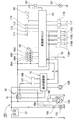
図16は本発明に係る表示装置を搭載した運輸手段の制御システム図である。小型艇の制御システム100は、電源供給源であるバッテリ27と、燃料噴射装置61(図4参照)のインジェクタ69(ここでは、「インジェクタ69A〜69D」と表示する)と、メインリレー91と、表示装置70(図5参照)に搭載した表示制御部74と、エンジン15(図1参照)の制御をする制御部(ECU)101と、を主要構成とするシステムである。
【0062】
図中、102はスタータ、103はスタータ102をON/OFFするスタータ用リレー、104は発電機、105は発電機で発電した電圧を調整するレギュレータ、107は表示制御部74に接続したブザー、108は表示制御部74に接続した速度センサ、109は表示制御部74に接続したフューエルセンサ、111は制御部(ECU)101に接続した温度センサ、112は制御部(ECU)101に接続した水温センサ、113は制御部(ECU)101に接続した排気温度検出センサ、114は制御部(ECU)101に接続することでエンジンオイルの温度を検出するオイル温度センサ、116A〜116Dは点火系部材(点火プラグ及びイグニションコイル)、117はオイル圧力センサ、118はエンジン15のノッキンングを検出するノックセンサ、121はフューエルポンプ、122はフューエルポンプをON/OFFするリレーを示す。
【0063】
矢印Aで示す流れは、制御部(ECU)101から表示制御部74に送るエンジンオイル情報、温度情報、フューエル情報、エンジン回転数情報、警告灯表示情報、OTS(Off Throttle Steering System)情報を示す。
また、矢印Bで示す流れは、表示制御部74から制御部(ECU)101に送るロック情報、制限運転情報を示す。
【0064】
尚、実施の形態では図12に示すように、症状を表示灯の点滅パターン(例えば、1回点滅、2回点滅又は3回点滅等)で表示するようにしたが、これに限るものではなく、例えば、表示灯の点灯とともにブザーを鳴らすようにしたもの若しくはブザーのみを鳴らすようにしたものであってもよい。
【0065】
【発明の効果】
本発明は上記構成により次の効果を発揮する。
一般的に、燃料噴射装置は空気と燃料とを混合し気化させた混合気をエンジンに送る装置であり、例えば、燃料噴射装置に異常が発生した場合には、吸気系統の異常なのか、燃料供給系統の異常なのか又はこれら以外の異常なのか判別するのが困難である。
請求項1では、多機能表示部に、燃料噴射装置に異常が生じたことを警告する警告灯を設け、この警告灯を点灯若しくは点滅させるようにするとともに、この警告灯が点灯若しくは点滅したときに操作スイッチを操作することで異常の症状を点滅パターンにて表示する機能を備え、操作スイッチに、時刻などを設定するときに使用するセットスイッチと、切換え表示部の切換えを設定するときに使用するモードスイッチとが設けられ、セットスイッチを長押ししたときに、エンジンの出力を低く制限する制限運転とエンジンの出力を制限しない通常運転とを切換えるとともに、セットスイッチとモードスイッチとを同時に長押ししたときに、故障診断を行うようにしたので、燃料噴射装置のトラブルに対して迅速な処置をすることができる。この結果、燃料噴射装置のトラブル解決の利便性の向上を図ることができる。
請求項2は、セットスイッチ及びモードスイッチの下方に、IDナンバを打込み決定するときに使用するIDセットスイッチと、IDナンバを入力するIDナンバスイッチとが設けられる。
【図面の簡単な説明】
【図1】本発明に係る表示装置を搭載した運輸手段の側面図
【図2】本発明に係る表示装置を搭載した運輸手段の平面図
【図3】本発明に係る表示装置を搭載した運輸手段の転舵機構の平面図
【図4】本発明に係る表示装置を搭載した運輸手段のOTS制御装置のブロック図
【図5】図1の5矢視図
【図6】本発明に係る表示装置を搭載した運輸手段の表示装置の平面断面図
【図7】本発明に係る表示装置を搭載した運輸手段の電源システムのブロック図
【図8】本発明に係る表示装置を搭載した運輸手段のランヤードスイッチ付きメインスイッチの側面図
【図9】本発明に係る表示装置を搭載した運輸手段のランヤードスイッチ付きメインスイッチの作用図
【図10】本発明に係る表示装置を搭載した運輸手段の電源システムの作用説明図
【図11】本発明に係る表示装置を搭載した運輸手段の制限運転設定のフロー図
【図12】本発明に係る表示装置を搭載した運輸手段の故障診断の手順を示すフロー図
【図13】本発明に係る表示装置を搭載した運輸手段の盗難防止機能の施錠/解除の手順を示すフロー図
【図14】本発明に係る表示装置を搭載した運輸手段の盗難防止機能のID新規登録/ID強制解除の手順を示すフロー図
【図15】本発明に係る表示装置を搭載した運輸手段の盗難防止機能の登録IDナンバ変更の手順を示すフロー図
【図16】本発明に係る表示装置を搭載した運輸手段の制御システム図
【符号の説明】
10…運輸手段(ジェット推進艇)、61…燃料噴射装置、70…表示装置、72…警告灯、73…操作スイッチ、78…多機能表示部。[0001]
BACKGROUND OF THE INVENTION
The present invention relates to a display device for transportation means having a fuel injection device for injecting fuel into a drive source. The transportation means refers to general transportation means including ships, airplanes, railways, vehicles, and the like.
[0002]
[Prior art]
As a display device for transportation means, for example, Japanese Patent Application Laid-Open No. 9-169298 “Starter for Small Ship” is known.
According to FIGS. 2 and 3 of the same publication, the above technique is provided with a control means E on the
[0003]
[Problems to be solved by the invention]
In the starter for a small boat, the boat speed can be displayed on the
That is, there is a demand for a display device that can alert not only the operation status of the transportation means but also the abnormality of the transportation means and also determine the symptoms of the abnormality.
[0004]
Accordingly, an object of the present invention is to provide a display device capable of displaying not only the operation status of the transportation means but also the abnormality of the transportation means and determining even the symptoms of the abnormality.
[0005]
[Means for Solving the Problems]
In order to achieve the above object, a display device for transportation means according to claim 1 includes a multi-function display unit that displays driving information and various warnings, an operation switch that operates display contents of the multi-function display unit, and a drive source. In a transportation means including a fuel injection device for injecting fuel, a warning light for warning that an abnormality has occurred in the fuel injection device is provided on the multi-function display unit, and the warning light is turned on or blinked. Along with this, a function to display abnormal symptoms in a blinking pattern by operating the operation switch when this warning light is lit or flashing, a set switch used to set the time etc. to the operation switch, A mode switch used to set the switching of the switching display is provided,When the set switch is held down for a long time, it switches between limited operation that limits the engine output low and normal operation that does not limit the engine output,Set switch and mode switchWhenIt is characterized in that a failure diagnosis is performed when long-pressing at the same time.
[0006]
In general, a fuel injection device is a device that sends an air-fuel mixture, which is a mixture of air and fuel, to an engine. For example, if an abnormality occurs in the fuel injection device, whether the intake system is abnormal or fuel It is difficult to determine whether the supply system is abnormal or any other abnormality.
[0007]
Therefore, a warning lamp is provided to warn that an abnormality has occurred in the fuel injection device, thereby notifying the abnormality of the fuel injection device. Moreover, it is emphasized that the fuel injection device is abnormal by lighting or blinking the warning light. Furthermore, by providing a function of displaying an abnormal symptom in a blinking pattern by operating the operation switch when the warning light is turned on or blinking, a quick action is taken against a trouble of the fuel injection device.
In other words, it has a function to display abnormal symptoms in a blinking pattern by operating the operation switch when the warning light is lit or blinking, and it can be switched with a set switch used to set the time etc. on the operation switch A mode switch is provided for use when setting the display switching.When the set switch is held down for a long time, it switches between limited operation that limits the engine output low and normal operation that does not limit the engine output,Set switch and mode switchWhenBy simultaneously pressing and holding, the trouble diagnosis is performed to improve the convenience of troubleshooting the fuel injection device.The
Claim2Is characterized in that an ID set switch for use in determining an ID number and an ID number switch for inputting the ID number are provided below the set switch and the mode switch.
[0008]
DETAILED DESCRIPTION OF THE INVENTION
Embodiments of the present invention will be described below with reference to the accompanying drawings. The drawings are viewed in the direction of the reference numerals.
FIG. 1 is a side view of a transportation means equipped with a display device according to the present invention. A
[0009]
The
According to the
[0010]
The
[0011]
According to the
Moreover, as will be described later, the
[0012]
In the figure, 26 is a reverse bucket for flowing a jet water flow obliquely forward and downward when the boat is to be backed, 33 is an operation knob for operating the
[0013]
FIG. 2 is a plan view of the transportation means equipped with the display device according to the present invention. The
[0014]
FIG. 3 is a plan view of the steering mechanism of the transportation means equipped with the display device according to the present invention. The
[0015]
FIG. 4 is a block diagram of an OTS control device for transportation means equipped with a display device according to the present invention. Here, OTS is an abbreviation for Off Throttle Steering System.64This is a device that makes it possible to maintain a predetermined jet water flow for a short time even when the pressure is returned.
The jet propulsion boat
[0016]
The
[0017]
FIG. 5 is a view taken in the direction of
The
[0018]
The
[0019]
The
[0020]
That is, the jet propulsion boat 10 (see FIG. 1) is also a propulsion boat having an anti-theft function that can be turned on or off by inputting an ID number.
[0021]
The
[0022]
FIG. 6 is a plan sectional view of a display device of a transportation means equipped with a display device according to the present invention. A
81b is a boss that supports the
[0023]
FIG. 7 is a block diagram of a power supply system for a transportation means equipped with a display device according to the present invention. A
The control unit (ECU) 101 is a part that controls the jet propulsion boat 10 (see FIG. 1) that controls the
[0024]
The
[0025]
That is, the
[0026]
A
[0027]
Further, the
[0028]
That is, in the
When the information for turning off the
[0029]
FIG. 8 is a side view of a main switch with a lanyard switch of a transportation means equipped with a display device according to the present invention. The main switch with a
The
[0030]
The
[0031]
When the
[0032]
FIGS. 9A to 9C are operation diagrams of the main switch with lanyard switch of the transportation means equipped with the display device according to the present invention.
In (a), by pushing the
[0033]
In (b), the
[0034]
In (c), between the
[0035]
10 (a) to 10 (c) are explanatory views of the operation of the power supply system of the transportation means equipped with the display device according to the present invention, and show the relationship among the main relay, the display device, the start switch, and the operating state of the engine. (See FIG. 8).
In (a), the operational relationship when the
First, as described in FIGS. 9A to 9C, the
[0036]
In (b), when the
[0037]
In (c), the operational relationship when the
When the
[0038]
Power system 90 (FIG.When the
[0039]
For example, when the power is turned on, the control unit often performs a fault diagnosis of a display device or auxiliary equipment. Therefore, if the control unit is turned off carelessly, it takes time to start up the control unit.
Therefore, when the main switch is in the off state for a predetermined time, the control unit maintains the on state so that the main switch 45 (FIG.(See FIG. 1), the
[0040]
FIG. 11 is a flow chart for setting the limited operation of the transportation means equipped with the display device according to the present invention. STxxx indicates a step number.
ST101: Set to a limited operation mode in which the output of the engine 15 (see FIG. 1) is limited to be low. Specifically, the
That is, by setting the limit operation, the limit
ST102: During the limited operation, the limit
ST103: Cancel the limited operation mode. Specifically, the
[0041]
The
[0042]
For example, a small boat (jet propulsion boat 10) that can be switched from a normal operation that does not restrict the output of the engine 15 (see FIG. 1) to a restricted operation that restricts the output of the
[0043]
Further, it can be said that the
By blinking the indicator lamp (limit
[0044]
Further, it can be said that the
Since the changeover switch (set
[0045]
FIG. 12 is a flowchart showing the procedure of failure diagnosis of the transportation means equipped with the display device according to the present invention. STxxx indicates a step number.
ST201: When the
ST202: Perform failure diagnosis. Specifically, the
[0046]
For example, at this time, the
ST203: Cancel the failure diagnosis mode. Specifically, the
[0047]
The
[0048]
In general, a fuel injection device is a device that sends an air-fuel mixture, which is a mixture of air and fuel, to an engine. For example, if an abnormality occurs in the fuel injection device, whether the intake system is abnormal or fuel It is difficult to determine whether the supply system is abnormal or any other abnormality.
[0049]
Therefore, a warning is given that an abnormality has occurred in the fuel injection device 61 (see FIG. 4).ForThe warning
That is, a function for displaying an abnormal symptom in a blinking pattern by operating the
[0050]
FIG. 13 is a flowchart showing a procedure for locking / releasing the anti-theft function of the transportation means equipped with the display device according to the present invention (see FIG. 7 for the reference numerals). STxxx indicates a step number.
ST301: The
ST302: It is determined whether or not the ID lock (theft prevention function) is turned on. If yes, go to ST303, if noST308Proceed to
ST303: Input the ID number using the
ST304: It is determined whether or not the ID number is correct. If yes, ST307If NO, return to ST302 via ST305 and ST306.
[0051]
ST305: A buzzer warning is issued.
ST306: Display that the ID number is different as a result of collation (collation NG display). That is, the
ST307: Release the ID lock.
ST308: Unlock the control unit (ECU) 101.
ST309: The
[0052]
ST310: Long press the ID set
ST311: An ID lock setting waiting display is displayed on the
ST312: Press the ID set
ST313: ID lock is locked.
ST314: The control unit (ECU) 101 is locked, and the display device 70 (see FIG. 4) cannot be operated.
ST315: The
[0053]
14 (a) and 14 (b) are flowcharts showing the procedure of new ID registration / forced ID release of the anti-theft function of the transportation means equipped with the display device according to the present invention (see FIG. 5 for the reference numerals). STxxx indicates a step number.
In (a), the procedure of ID new registration of ID lock (anti-theft function) is shown.
ST401: The main switch 45 (see FIG. 7) is turned on.
ST402: Long press the
ST403: The ID number is input by the
ST404: A new ID number can be registered by long pressing the ID set
Thereafter, the process is terminated through steps ST309 to ST312 shown in FIG.
[0054]
FIG. 6B shows a procedure for forcibly releasing ID of the ID lock (theft prevention function).
ST501: Open the fuel signal. That is, the harness from the fuel sensor (not shown) of the
ST502: The main switch 45 (see FIG. 7) is turned on.
ST503: Press and hold the
ST504: The release number as a predetermined number is input by the
[0055]
ST505: The ID number is reset. ID number is resetAndWhen the initial value is “000”, the ID lock cannot be applied and the ID number is input again.
ST506: The
ST507: The fuel signal is closed. That is, the removed harness is restored.
That is, the ID number can be forcibly released by the operation of ST501 to ST505, and the ID number can be reset.
When it is newly used, it is performed again from the new registration of the ID number.
[0056]
The security code releasing method of the anti-theft function in the transport means (jet propulsion boat 10) is a function of the anti-theft function in the transport means having an anti-theft function that allows the passenger to turn on the power by inputting the security code. By removing at least one of the plurality of
[0057]
For example, replacing the entire anti-theft function in response to an unexpected situation where the operator or owner has forgotten the PIN number will cause an increase in repair costs. On the other hand, the anti-theft function cannot be maintained if the password can be easily reset.
Therefore, by removing at least one of the plurality of
[0058]
FIG. 15 is a flowchart showing the procedure for changing the registration ID number of the anti-theft function of the transportation means equipped with the display device according to the present invention (see FIG. 5 for the reference numerals). STxxx indicates a step number.
ST601: Long press the
ST602: Input a registered ID number.
ST603: The input ID number blinks.
ST604:ID set switch 73cPress and hold. Here, the long press time is set to 2 sec or more.
[0059]
ST605: It is determined whether or not the ID number is correct. If YES, the process proceeds to ST506, and if NO, the process returns to ST602 via ST607 and ST608. In addition, the allowable number of inputs of this ID number was set to 3 times. That is, if a mistake is made three times, the power of the display device 70 (see FIG. 4) is turned off.
ST606: Enter a new ID number.
ST607: A buzzer warning is given.
ST608: A display indicating that the ID number is different as a result of collation (collation NG display) is displayed. That is, the
[0060]
ST609: The new ID number is blinked.
ST610: Long press the ID set
ST611: Displaying completion of registration by turning on the new ID number.
[0061]
FIG. 16 is a control system diagram of a transportation means equipped with a display device according to the present invention. The small
[0062]
In the figure, 102 is a starter, 103 is a relay for a starter that turns ON / OFF the
[0063]
A flow indicated by an arrow A indicates engine oil information, temperature information, fuel information, engine speed information, warning light display information, and OTS (Off Throttle Steering System) information sent from the control unit (ECU) 101 to the
The flow indicated by the arrow B flows from the
[0064]
In the embodiment, as shown in FIG. 12, the symptom is displayed by the blinking pattern of the indicator lamp (for example, blinking once, blinking twice, blinking three times, etc.), but the present invention is not limited to this. For example, the display lamp may be turned on and the buzzer may be sounded or only the buzzer may be sounded.
[0065]
【The invention's effect】
The present invention exhibits the following effects by the above configuration.
In general, a fuel injection device is a device that sends an air-fuel mixture, which is a mixture of air and fuel, to an engine. For example, if an abnormality occurs in the fuel injection device, whether the intake system is abnormal or fuel It is difficult to determine whether the supply system is abnormal or any other abnormality.
In claim 1, the multi-function display unit is provided with a warning light for warning that an abnormality has occurred in the fuel injection device, and the warning light is turned on or blinked, and when the warning light is turned on or blinked A function to display abnormal symptoms in a blinking pattern by operating the operation switch is used, and it is used to set the switch to be used when setting the time, etc., and the changeover display section. Mode switch to be provided,When the set switch is held down for a long time, it switches between limited operation that limits the engine output low and normal operation that does not limit the engine output,Set switch and mode switchWhenSince the failure diagnosis is performed when long-pressing at the same time, it is possible to take a quick measure against the trouble of the fuel injection device. As a result, it is possible to improve the convenience of troubleshooting the fuel injection device.The
Claim2Are provided below the set switch and the mode switch are an ID set switch used when an ID number is input and determined, and an ID number switch for inputting the ID number.
[Brief description of the drawings]
FIG. 1 is a side view of a transportation means equipped with a display device according to the present invention.
FIG. 2 is a plan view of transportation means equipped with a display device according to the present invention.
FIG. 3 is a plan view of a steering mechanism of a transportation means equipped with a display device according to the present invention.
FIG. 4 is a block diagram of an OTS control device for transportation means equipped with a display device according to the present invention.
FIG. 5 is a view taken in the direction of
FIG. 6 is a plan sectional view of a display device of a transportation means equipped with a display device according to the present invention.
FIG. 7 is a block diagram of a power supply system for transportation means equipped with a display device according to the present invention.
FIG. 8 is a side view of a main switch with a lanyard switch of a transportation means equipped with a display device according to the present invention.
FIG. 9 is an operation diagram of a main switch with a lanyard switch of a transportation means equipped with a display device according to the present invention.
FIG. 10 is a diagram for explaining the operation of the power supply system of the transportation means equipped with the display device according to the present invention.
FIG. 11 is a flow chart of setting of limited operation of transportation means equipped with a display device according to the present invention.
FIG. 12 is a flowchart showing a procedure for failure diagnosis of a transportation means equipped with a display device according to the present invention.
FIG. 13 is a flowchart showing a procedure for locking / releasing the anti-theft function of a transportation means equipped with a display device according to the present invention.
FIG. 14 is a flowchart showing a procedure for new ID registration / forced ID release of the anti-theft function of a transportation means equipped with a display device according to the present invention;
FIG. 15 is a flowchart showing a procedure for changing the registration ID number of the anti-theft function of a transportation means equipped with a display device according to the present invention;
FIG. 16 is a control system diagram of a transportation means equipped with a display device according to the present invention.
[Explanation of symbols]
DESCRIPTION OF
Claims (2)
前記多機能表示部に、前記燃料噴射装置に異常が生じたことを警告する警告灯を設け、この警告灯を点灯若しくは点滅させるようにするとともに、この警告灯が点灯若しくは点滅したときに前記操作スイッチを操作することで前記異常の症状を点滅パターンにて表示する機能を備え、
前記操作スイッチに、時刻などを設定するときに使用するセットスイッチと、切換え表示部の切換えを設定するときに使用するモードスイッチとが設けられ、
前記セットスイッチを長押ししたときに、エンジンの出力を低く制限する制限運転とエンジンの出力を制限しない通常運転とを切換えるとともに、
前記セットスイッチと前記モードスイッチとを同時に長押ししたときに、故障診断を行うようにしたことを特徴とする運輸手段の表示装置。In a transportation means comprising a multi-function display unit for displaying operation information and various warnings, an operation switch for operating display contents of the multi-function display unit, and a fuel injection device for injecting fuel to a drive source,
The multi-function display unit is provided with a warning light for warning that an abnormality has occurred in the fuel injection device, and the warning light is turned on or blinked. With the function to display the symptoms of the abnormality in a blinking pattern by operating the switch,
The operation switch is provided with a set switch used when setting the time and the like, and a mode switch used when setting switching of the switching display section,
When the set switch is held down for a long time, switching between a limited operation that limits the engine output to a low level and a normal operation that does not limit the engine output,
When you press and hold and the mode switch and the set switch simultaneously, the display device of the transportation means, characterized in that to perform the fault diagnosis.
Priority Applications (3)
| Application Number | Priority Date | Filing Date | Title |
|---|---|---|---|
| JP2001283563A JP4097921B2 (en) | 2001-09-18 | 2001-09-18 | Display device for means of transportation |
| US10/238,580 US6864806B2 (en) | 2001-09-18 | 2002-09-11 | Display apparatus for transportation means |
| CA002403471A CA2403471C (en) | 2001-09-18 | 2002-09-16 | Display apparatus for transportation means |
Applications Claiming Priority (1)
| Application Number | Priority Date | Filing Date | Title |
|---|---|---|---|
| JP2001283563A JP4097921B2 (en) | 2001-09-18 | 2001-09-18 | Display device for means of transportation |
Publications (2)
| Publication Number | Publication Date |
|---|---|
| JP2003089322A JP2003089322A (en) | 2003-03-25 |
| JP4097921B2 true JP4097921B2 (en) | 2008-06-11 |
Family
ID=19107035
Family Applications (1)
| Application Number | Title | Priority Date | Filing Date |
|---|---|---|---|
| JP2001283563A Expired - Fee Related JP4097921B2 (en) | 2001-09-18 | 2001-09-18 | Display device for means of transportation |
Country Status (3)
| Country | Link |
|---|---|
| US (1) | US6864806B2 (en) |
| JP (1) | JP4097921B2 (en) |
| CA (1) | CA2403471C (en) |
Families Citing this family (13)
| Publication number | Priority date | Publication date | Assignee | Title |
|---|---|---|---|---|
| JP4219152B2 (en) * | 2002-10-31 | 2009-02-04 | ヤマハマリン株式会社 | Oil change timing warning device for ship propulsion equipment |
| JP2004359189A (en) * | 2003-06-09 | 2004-12-24 | Kawasaki Heavy Ind Ltd | Self-diagnosis information processing method and self-diagnosis information processing device for small planing boat |
| JP2005164743A (en) * | 2003-11-28 | 2005-06-23 | Yamaha Marine Co Ltd | Engine condition indicating device for boat |
| US7571032B2 (en) * | 2004-01-06 | 2009-08-04 | Yamaha Hatsudoki Kabushiki Kaisha | Display device for watercraft |
| JP2005319895A (en) * | 2004-05-10 | 2005-11-17 | Kawasaki Heavy Ind Ltd | Stand riding type small planing boat |
| US7441189B2 (en) * | 2005-06-20 | 2008-10-21 | Navico International Limited | Instrumentation interface display customization |
| EP1935723A4 (en) * | 2005-09-20 | 2010-12-22 | Fujitsu Ten Ltd | In-vehicle display device |
| US7750796B2 (en) * | 2006-06-27 | 2010-07-06 | Gm Global Technology Operations, Inc. | Regenerative braking halo and method |
| US20100184342A1 (en) * | 2007-10-09 | 2010-07-22 | Brunswick Corporation | Method for responding to a missing marine propulsion device |
| JP2009092027A (en) * | 2007-10-11 | 2009-04-30 | Yamaha Motor Co Ltd | Malfunction detecting device for fuel pump |
| JP2012013452A (en) * | 2010-06-29 | 2012-01-19 | Honda Motor Co Ltd | Meter device for motor cycle |
| CN103963650A (en) * | 2013-01-30 | 2014-08-06 | 爱思恩梯大宇汽车部件(昆山)有限公司 | Automobile instrument assembly structure |
| US10220806B2 (en) * | 2017-08-02 | 2019-03-05 | Ford Global Technologies, Llc | Monitoring and alerting vehicle occupants for ignition systems |
Family Cites Families (8)
| Publication number | Priority date | Publication date | Assignee | Title |
|---|---|---|---|---|
| US4836809A (en) * | 1988-03-11 | 1989-06-06 | Twin Disc, Incorporated | Control means for marine propulsion system |
| US5043727A (en) * | 1989-02-03 | 1991-08-27 | Sanshin Kogyo Kabushiki Kaisha | Display system for marine vessel |
| JP3437041B2 (en) | 1995-10-18 | 2003-08-18 | ヤマハ発動機株式会社 | Starter for small boats |
| JP3501899B2 (en) * | 1996-04-15 | 2004-03-02 | ヤマハ発動機株式会社 | Exhaust system for ship propulsion |
| JP3694092B2 (en) * | 1996-04-16 | 2005-09-14 | ヤマハ発動機株式会社 | Small ship |
| JPH1113544A (en) * | 1997-06-26 | 1999-01-19 | Yamaha Motor Co Ltd | Carburetor device for multicylinder engine |
| JPH11101172A (en) * | 1997-09-26 | 1999-04-13 | Yamaha Motor Co Ltd | Exhaust device for marine engine |
| US6382122B1 (en) * | 2001-06-22 | 2002-05-07 | Brunswick Corporation | Method for initializing a marine vessel control system |
-
2001
- 2001-09-18 JP JP2001283563A patent/JP4097921B2/en not_active Expired - Fee Related
-
2002
- 2002-09-11 US US10/238,580 patent/US6864806B2/en not_active Expired - Lifetime
- 2002-09-16 CA CA002403471A patent/CA2403471C/en not_active Expired - Fee Related
Also Published As
| Publication number | Publication date |
|---|---|
| CA2403471A1 (en) | 2003-03-18 |
| US6864806B2 (en) | 2005-03-08 |
| CA2403471C (en) | 2006-02-21 |
| US20030067384A1 (en) | 2003-04-10 |
| JP2003089322A (en) | 2003-03-25 |
Similar Documents
| Publication | Publication Date | Title |
|---|---|---|
| JP4097921B2 (en) | Display device for means of transportation | |
| JP5081102B2 (en) | Ship theft deterrent device and ship equipped with the same | |
| JP4181198B2 (en) | Vehicle theft prevention system and vehicle theft prevention method | |
| JP4005324B2 (en) | Small boat display device | |
| US8515603B2 (en) | Antitheft apparatus for equipment with prime mover | |
| JP4108308B2 (en) | How to cancel your PIN code | |
| JP4097922B2 (en) | Liquid crystal display device for jet propulsion boat | |
| JP4166998B2 (en) | Small boat power supply system | |
| JP4144741B2 (en) | Vehicle anti-theft device | |
| US6960105B2 (en) | Jet propulsion boat | |
| JP4172297B2 (en) | Anti-theft device for vehicles, etc. | |
| CA2404114C (en) | Method for releasing secret number of theft prevention function in transportation means | |
| JP2006266097A (en) | Engine controller | |
| JP3872078B2 (en) | Moving body starting system | |
| JP3967100B2 (en) | Jet propulsion boat | |
| JP4021636B2 (en) | Jet propulsion boat | |
| JP2006175999A (en) | Antitheft system for outboard engine | |
| CN113389670A (en) | Authentication device for saddle-ride type vehicle |
Legal Events
| Date | Code | Title | Description |
|---|---|---|---|
| A621 | Written request for application examination |
Free format text: JAPANESE INTERMEDIATE CODE: A621 Effective date: 20041203 |
|
| A131 | Notification of reasons for refusal |
Free format text: JAPANESE INTERMEDIATE CODE: A131 Effective date: 20070612 |
|
| A521 | Request for written amendment filed |
Free format text: JAPANESE INTERMEDIATE CODE: A523 Effective date: 20070711 |
|
| A02 | Decision of refusal |
Free format text: JAPANESE INTERMEDIATE CODE: A02 Effective date: 20071120 |
|
| A521 | Request for written amendment filed |
Free format text: JAPANESE INTERMEDIATE CODE: A523 Effective date: 20071212 |
|
| A911 | Transfer to examiner for re-examination before appeal (zenchi) |
Free format text: JAPANESE INTERMEDIATE CODE: A911 Effective date: 20080128 |
|
| TRDD | Decision of grant or rejection written | ||
| A01 | Written decision to grant a patent or to grant a registration (utility model) |
Free format text: JAPANESE INTERMEDIATE CODE: A01 Effective date: 20080311 |
|
| A61 | First payment of annual fees (during grant procedure) |
Free format text: JAPANESE INTERMEDIATE CODE: A61 Effective date: 20080312 |
|
| R150 | Certificate of patent or registration of utility model |
Free format text: JAPANESE INTERMEDIATE CODE: R150 |
|
| FPAY | Renewal fee payment (event date is renewal date of database) |
Free format text: PAYMENT UNTIL: 20110321 Year of fee payment: 3 |
|
| FPAY | Renewal fee payment (event date is renewal date of database) |
Free format text: PAYMENT UNTIL: 20110321 Year of fee payment: 3 |
|
| FPAY | Renewal fee payment (event date is renewal date of database) |
Free format text: PAYMENT UNTIL: 20120321 Year of fee payment: 4 |
|
| FPAY | Renewal fee payment (event date is renewal date of database) |
Free format text: PAYMENT UNTIL: 20130321 Year of fee payment: 5 |
|
| FPAY | Renewal fee payment (event date is renewal date of database) |
Free format text: PAYMENT UNTIL: 20130321 Year of fee payment: 5 |
|
| FPAY | Renewal fee payment (event date is renewal date of database) |
Free format text: PAYMENT UNTIL: 20140321 Year of fee payment: 6 |
|
| LAPS | Cancellation because of no payment of annual fees |