EP1872656A2 - Fishing pole - Google Patents
Fishing pole Download PDFInfo
- Publication number
- EP1872656A2 EP1872656A2 EP07251464A EP07251464A EP1872656A2 EP 1872656 A2 EP1872656 A2 EP 1872656A2 EP 07251464 A EP07251464 A EP 07251464A EP 07251464 A EP07251464 A EP 07251464A EP 1872656 A2 EP1872656 A2 EP 1872656A2
- Authority
- EP
- European Patent Office
- Prior art keywords
- fishing
- pole
- fishing pole
- aperture
- arrangement according
- Prior art date
- Legal status (The legal status is an assumption and is not a legal conclusion. Google has not performed a legal analysis and makes no representation as to the accuracy of the status listed.)
- Granted
Links
Images


Classifications
-
- A—HUMAN NECESSITIES
- A01—AGRICULTURE; FORESTRY; ANIMAL HUSBANDRY; HUNTING; TRAPPING; FISHING
- A01K—ANIMAL HUSBANDRY; CARE OF BIRDS, FISHES, INSECTS; FISHING; REARING OR BREEDING ANIMALS, NOT OTHERWISE PROVIDED FOR; NEW BREEDS OF ANIMALS
- A01K87/00—Fishing rods
- A01K87/002—Fishing rods with the line passing through the hollow rod
Definitions
- This invention relates to fishing pole arrangements, fishing pole sections and bushes for use therein. More particularly, the invention relates to fishing pole arrangements and components for use therein which allow the angler to control the length, tension and/or elasticity of the integral pole elastic while playing and landing fish.
- Modern day anglers increasingly use fishing poles which are of lightweight hollow tubular form, typically being constructed of carbon fibre material. These fishing poles enable very accurate positioning of the angler's float.
- FIG. 1 of the accompanying drawings A typical conventional design of fishing pole is shown in Figure 1 of the accompanying drawings and consists of a number of hollow tapered tubular sections 10 1 to 10 10 that fit together by fitting the front end of a rear section into the rear end of a forward section. The foremost is numbered '1' and the others in sequence. Over the length of the pole, these sections become smaller in diameter by a gradual taper, towards the terminal or tip section 1 through which the fishing line 12 passes to be attached to the float. Within the foremost pole sections (typically one, two or three) a length of rubber thread 14 is inserted to act as a shock absorber when retrieving a hooked fish. The thread 14 is connected to the line 12 by means of a slip connector 15. Referring to Figure 2 of the accompanying drawings, the elastic 14 is normally anchored inside these sections by means of a bung-shaped accessory 16 that the elastic is tied to and which is trapped in the section 10 2 by the taper of the internal wall of the section.
- the pole is extended by adding successive sections 10 n to the rear end thereof until the tip lies over the required stretch of water.
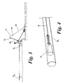
- the general technique is to pass the pole backwards through the angler's hands, keeping the pole horizontal, until the last two or three elasticated sections 10 1 , 10 2 are reached. These sections are then separated from the rest of the pole and the fish is guided into a landing net by raising these sections to an upright position as seen in Figure 3 of the accompanying drawings.
- the elasticated sections can be fitted with heavy or lighter elastics depending on the targeted fish size, with heavier elastics being suited to larger fish and lighter elastics for smaller fish.
- a similar effect to using a heavy elastic can be achieved by increasing the tension of a lighter elastic thread by reducing its effective length. This may be achieved by using an adapted bung accessory 17 that incorporates a facility to wind elastic on it, therefore reducing the length of the elastic in use and effectively providing a preload to the remaining elasticated line as shown in Figure 4 of the accompanying drawings.
- a problem with the above method of altering the pole elastic tension is that the angler is not able to access and alter the elastic tension device whilst landing a fish.
- the angler must therefore anticipate the likely size of fish to be caught before he assembles the pole. Also, this gives a fixed preload and does not allow the preload to be adjusted dynamically whilst landing the fish.
- this invention provides a fishing pole arrangement comprising a hollow tubular fishing pole with an open end at its forward tip, and an elastic fishing line at least a portion of which is elastically extendable, wherein the fishing pole has a side aperture in a side wall of the pole whereby the fishing line passes through the open end at the tip of the pole interiorly of the pole to exit through said side aperture to carry a stop means to anchor an end portion of the fishing line against passage through said side aperture.
- the term elastic fishing line is used to mean that the thread or filament is designed to undergo significant elastic extension compared to the line to which it is attached, so as to provide a shock absorbing effect.
- the elastic line may undergo extension of 100% or more in use, whereas the line to which it is attached may be designed to extend by well under 50%.
- the elastic fishing line may be a single length of elastic, or it may be made up of lengths of different elasticity elastics connected end to end, or a length of elastic connected end to end with one or more lengths of relatively inelastic material.
- the pole is made up of tubular sections adapted to fit together.
- the side aperture could be provided in the forward tip section, or in a section to the rear of the tip section, such as the second or third.
- the pole comprises a thin-walled tubular section
- a region of the tubular wall adjacent the side aperture may be locally thickened to reinforce it.
- said fishing line comprises an elastic element extending through said side aperture, and then interiorly of the fishing pole, to pass to the open end in said tip section, there to be connected to a relatively inelastic fishing line.
- the connector may be for example a slip connector.
- the stop means may comprise an enlarged region on the fishing line exteriorly of the side aperture, which could for example be provided by a knot in the fishing line, with or without a relatively rigid ring or bead.
- side aperture is provided with a guide to prevent the elastic line snagging on the side of the aperture.
- the aperture may be provided with a bush means inserted into a side wall of the fishing pole.
- the bush means may be formed of a low friction material, such as PTFE.
- this invention provides a fishing pole for use in the fishing pole arrangement described above, the pole being of hollow tubular form having an open end at its forward tip and side aperture in a side wall of the pole rearwardly of the tip but spaced a substantial distance from the rearward end of the pole.
- the pole may be made of a series of sections, with the side aperture provided in a section forwardly of the rearmost.
- this invention provides a fishing pole bush for use in a fishing pole described above, the bush comprising an inner guide surface for receiving a fishing line in use and shaped externally to be fitted into an aperture provided in the tubular wall of a fishing pole.
- the tip section 10 1 (first section) and second section 10 2 of a multi-pole section are shown as elasticated (i.e. an elastic thread passes along the inside of both). It will of course be appreciated that there could be more than two sections elasticated or indeed the elastic could pass down just through the first section 10 1 .
- the sections 10 1 , 10 2 are each made of thin walled carbon fibre composite material to give a stiff yet lightweight construction.
- An elastic thread 14 is connected to a conventional fishing line 12 (e.g.
- the modulus or elasticity of the elastic thread 14 varies in accordance with the amount of tension applied.
- the angler wishes to increase the elasticity of the elastic thread he can grab the end of the thread that protrudes through the aperture 18 and pull out a length of elastic through the side of the pole thereby reducing the elasticity of the remaining elastic inside. This can be done just momentarily, or for longer periods.
- the slip connector 15 is pulled clear of the tip of the pole, drawing the extended elastic thread with it.
- a bush 20 for fitting into the aperture 18 in the wall of the tube 10 1 to ensure that the elastic thread 14 can slip through the aperture 18 without damage.
- the bush 20 therefore provides a generally cylindrical bore 21 with a smoothly flared outer edge 22 and a tapered external section 24 terminating in an annular groove 26 and an enlarged head 28.
- the tapered section 24 and annular groove 26 are designed so that the bush 20 can be snap-fitted into an appropriately sized hole in the wall of a pole section.
- the axial length of the bush 20 ensures that the elastic thread 14 is held away from the inner walls of the pole section and near centre line of the pole section.
- the wall section of the pole is preferably locally enlarged to reinforce it, by provision of additional fibre plies 30.
- an integral guide may be formed in the wall of the pole during manufacture.
Abstract
Description
- This invention relates to fishing pole arrangements, fishing pole sections and bushes for use therein. More particularly, the invention relates to fishing pole arrangements and components for use therein which allow the angler to control the length, tension and/or elasticity of the integral pole elastic while playing and landing fish.
- Modern day anglers increasingly use fishing poles which are of lightweight hollow tubular form, typically being constructed of carbon fibre material. These fishing poles enable very accurate positioning of the angler's float.
- A typical conventional design of fishing pole is shown in Figure 1 of the accompanying drawings and consists of a number of hollow tapered
tubular sections 101 to 1010 that fit together by fitting the front end of a rear section into the rear end of a forward section. The foremost is numbered '1' and the others in sequence. Over the length of the pole, these sections become smaller in diameter by a gradual taper, towards the terminal or tip section 1 through which thefishing line 12 passes to be attached to the float. Within the foremost pole sections (typically one, two or three) a length ofrubber thread 14 is inserted to act as a shock absorber when retrieving a hooked fish. Thethread 14 is connected to theline 12 by means of aslip connector 15. Referring to Figure 2 of the accompanying drawings, the elastic 14 is normally anchored inside these sections by means of a bung-shaped accessory 16 that the elastic is tied to and which is trapped in thesection 102 by the taper of the internal wall of the section. - In use, the pole is extended by adding
successive sections 10n to the rear end thereof until the tip lies over the required stretch of water. Once a fish has been hooked, the general technique is to pass the pole backwards through the angler's hands, keeping the pole horizontal, until the last two or threeelasticated sections - The elasticated sections can be fitted with heavy or lighter elastics depending on the targeted fish size, with heavier elastics being suited to larger fish and lighter elastics for smaller fish. In addition, a similar effect to using a heavy elastic can be achieved by increasing the tension of a lighter elastic thread by reducing its effective length. This may be achieved by using an adapted
bung accessory 17 that incorporates a facility to wind elastic on it, therefore reducing the length of the elastic in use and effectively providing a preload to the remaining elasticated line as shown in Figure 4 of the accompanying drawings. - A problem with the above method of altering the pole elastic tension is that the angler is not able to access and alter the elastic tension device whilst landing a fish. The angler must therefore anticipate the likely size of fish to be caught before he assembles the pole. Also, this gives a fixed preload and does not allow the preload to be adjusted dynamically whilst landing the fish.
- Accordingly, we have designed a system which allows the pole elastic tension to be adjusted whilst landing a fish. The ability to control the tension means that the angler can target small fish using a light elastic, whilst at the same time being able to effect the landing of larger fish should one be hooked, by increasing the elastic tension on landing the fish.
- Accordingly, in one aspect, this invention provides a fishing pole arrangement comprising a hollow tubular fishing pole with an open end at its forward tip, and an elastic fishing line at least a portion of which is elastically extendable, wherein the fishing pole has a side aperture in a side wall of the pole whereby the fishing line passes through the open end at the tip of the pole interiorly of the pole to exit through said side aperture to carry a stop means to anchor an end portion of the fishing line against passage through said side aperture.
- The term elastic fishing line is used to mean that the thread or filament is designed to undergo significant elastic extension compared to the line to which it is attached, so as to provide a shock absorbing effect. Thus the elastic line may undergo extension of 100% or more in use, whereas the line to which it is attached may be designed to extend by well under 50%. The elastic fishing line may be a single length of elastic, or it may be made up of lengths of different elasticity elastics connected end to end, or a length of elastic connected end to end with one or more lengths of relatively inelastic material.
- In this manner an end of the fishing line protrudes externally through the side aperture so the angler can grab the end of the line to vary the preload/tension. Preferably the pole is made up of tubular sections adapted to fit together. Depending on the length of the sections, the side aperture could be provided in the forward tip section, or in a section to the rear of the tip section, such as the second or third.
- Where as is customary in many instances, the pole comprises a thin-walled tubular section, a region of the tubular wall adjacent the side aperture may be locally thickened to reinforce it.
- Conveniently, said fishing line comprises an elastic element extending through said side aperture, and then interiorly of the fishing pole, to pass to the open end in said tip section, there to be connected to a relatively inelastic fishing line. The connector may be for example a slip connector.
- The stop means may comprise an enlarged region on the fishing line exteriorly of the side aperture, which could for example be provided by a knot in the fishing line, with or without a relatively rigid ring or bead.
- Conveniently, side aperture is provided with a guide to prevent the elastic line snagging on the side of the aperture. Thus the aperture may be provided with a bush means inserted into a side wall of the fishing pole. The bush means may be formed of a low friction material, such as PTFE.
- In another aspect, this invention provides a fishing pole for use in the fishing pole arrangement described above, the pole being of hollow tubular form having an open end at its forward tip and side aperture in a side wall of the pole rearwardly of the tip but spaced a substantial distance from the rearward end of the pole. The pole may be made of a series of sections, with the side aperture provided in a section forwardly of the rearmost.
- In yet another aspect, this invention provides a fishing pole bush for use in a fishing pole described above, the bush comprising an inner guide surface for receiving a fishing line in use and shaped externally to be fitted into an aperture provided in the tubular wall of a fishing pole.
- Whilst the invention has been described above, it extends to any inventive combination of the features set out above or in the following description.
- The invention may be performed in various ways, and an embodiment thereof will now be described by way of example only, reference being made to the accompanying drawings in which:
- Figure 1 is a schematic view showing an existing multiple section fishing pole to position the float at a desired location over a stretch of water;
- Figure 2 is a schematic view showing the top two elasticated pole sections in a conventional fishing pole of the type shown in Figure 1;
- Figure 3 is a schematic view showing the top two elasticated sections detached from the remainder of the pole whilst the angler lands a fish;
- Figure 4 is a schematic view of a fitting of a prior art bung into the rear end of an elasticated pole section;
- Figure 5 is a schematic view of the two elasticated sections of a fishing pole arrangement in accordance with this invention;
- Figures 6(a), (b), (c) and (d) are respective side, front, rear and section views of a bush for use in the embodiment of the invention illustrated in Figure 5, and
- Figure 7 is a cross-section view through a fishing pole section fitted with a bush of the type illustrated in Figures 6(a) to (d) illustrating the line of the elastic thread.
- Referring now to Figures 5 to 7, in this embodiment the tip section 101 (first section) and
second section 102 of a multi-pole section are shown as elasticated (i.e. an elastic thread passes along the inside of both). It will of course be appreciated that there could be more than two sections elasticated or indeed the elastic could pass down just through thefirst section 101. Thesections elastic thread 14 is connected to a conventional fishing line 12 (e.g. of nylon) by asuitable slip connector 15 at the tip of the pole and then runs down the inside of the pole through the full length of thetip section 101, down approximately two thirds of thesecond section 102, then to exit through aside aperture 18 in the wall of the tube to terminate in a knot orbead 20. - The modulus or elasticity of the
elastic thread 14 varies in accordance with the amount of tension applied. Thus, if the angler wishes to increase the elasticity of the elastic thread he can grab the end of the thread that protrudes through theaperture 18 and pull out a length of elastic through the side of the pole thereby reducing the elasticity of the remaining elastic inside. This can be done just momentarily, or for longer periods. In addition of course, as theline 12 comes under tension when a fish is on the line, theslip connector 15 is pulled clear of the tip of the pole, drawing the extended elastic thread with it. - Referring now to Figures 6 and 7, there is shown a
bush 20 for fitting into theaperture 18 in the wall of thetube 101 to ensure that theelastic thread 14 can slip through theaperture 18 without damage. It should be noted that the wall of the tube is very thin and might otherwise cut through the elastic. Thebush 20 therefore provides a generallycylindrical bore 21 with a smoothly flaredouter edge 22 and a taperedexternal section 24 terminating in anannular groove 26 and an enlargedhead 28. Thetapered section 24 andannular groove 26 are designed so that thebush 20 can be snap-fitted into an appropriately sized hole in the wall of a pole section. As will be seen, the axial length of thebush 20 ensures that theelastic thread 14 is held away from the inner walls of the pole section and near centre line of the pole section. In order to ensure that the pole section is not compromised by the provision of a hole in the side, and to accommodate the twisting loads transmitted by the bush in use, the wall section of the pole is preferably locally enlarged to reinforce it, by provision ofadditional fibre plies 30. Instead of a separate bush, an integral guide may be formed in the wall of the pole during manufacture.
Claims (19)
- A fishing pole arrangement comprising a hollow tubular fishing pole with an open end at its forward tip, and an elastic fishing line at least a portion of which is elastically extendable, characterised in that said fishing pole has a side aperture in a side wall of the pole whereby the fishing line passes through the open end at the tip of the pole interiorly of the pole to exit through said side aperture to carry a stop means to anchor an end portion of the fishing line against passage through said side aperture.
- A fishing pole arrangement according to Claim 1, wherein the pole is made up of tubular sections adapted to fit together.
- A fishing pole arrangement according to Claim 2, wherein the side aperture is provided in the forward tip section.
- A fishing pole arrangement according to Claim 2, wherein the aperture is provided in a section to the rear of the tip section.
- A fishing pole arrangement according to any of the preceding Claims, wherein the pole comprises a thin-walled tubular section, and a region of the tubular wall adjacent the aperture is locally thickened.
- A fishing pole arrangement according to any of the preceding Claims, wherein said fishing line comprises an elastic element extending through said side aperture, interiorly of the fishing pole, to pass to the open end in said tip section, there to be connected to a relatively inelastic fishing line.
- A fishing pole arrangement according to any of the preceding Claims, wherein the stop means comprises an enlarged region on the fishing line exteriorly of the side aperture.
- A fishing pole arrangement according to Claim 7, wherein the enlarged region includes a knot in the fishing line.
- A fishing pole arrangement according to Claim 7 or Claim 8, wherein the enlarged region includes a ring or bead.
- A fishing pole arrangement according any of the preceding Claims, wherein the side aperture is provided in a bush means inserted into a side wall of the fishing pole.
- A fishing pole arrangement according to Claim 10, wherein the bush means is formed of a low friction material.
- A fishing pole arrangement according Claim 10, wherein the bush means is formed of PTFE.
- A fishing pole for use in the fishing pole arrangement of any of the preceding Claims, of hollow tubular form having an open end at its forward tip and an aperture in a side wall of the pole rearwardly of the tip but spaced a substantial distance from the rearward end of the pole.
- A fishing pole according to Claim 13, made up of tubular sections, wherein said aperture is provided in the tip section.
- A fishing pole according to Claim 13, wherein said aperture is provided in a section rearwards of the tip section but forwardly of the rearmost section.
- A fishing pole bush for use in a fishing pole as claimed in any of the preceding Claims, comprising an inner guide surface for receiving a fishing line in use and shaped externally to be fitted into an aperture provided in the tubular wall of a fishing pole.
- A fishing pole arrangement substantially as hereinbefore described with reference to, and as illustrated in, any of Figures 4 to 6 of the accompanying drawings.
- A fishing pole substantially as hereinbefore described with reference to, and as illustrated in, any of Figures 4 to 6 of the accompanying drawings.
- A fishing pole bush substantially as hereinbefore described with reference to, and as illustrated in, any of Figures 4 to 6 of the accompanying drawings.
Applications Claiming Priority (2)
| Application Number | Priority Date | Filing Date | Title |
|---|---|---|---|
| GB0606516A GB0606516D0 (en) | 2006-03-31 | 2006-03-31 | Pole section with variable elastic tension |
| GB0703305A GB0703305D0 (en) | 2007-02-21 | 2007-02-21 | Protective PTFE Bush for Lining Hole in Side of Pole Section |
Publications (3)
| Publication Number | Publication Date |
|---|---|
| EP1872656A2 true EP1872656A2 (en) | 2008-01-02 |
| EP1872656A3 EP1872656A3 (en) | 2008-04-23 |
| EP1872656B1 EP1872656B1 (en) | 2010-11-10 |
Family
ID=38670350
Family Applications (1)
| Application Number | Title | Priority Date | Filing Date |
|---|---|---|---|
| EP07251464A Active EP1872656B1 (en) | 2006-03-31 | 2007-04-02 | Fishing pole |
Country Status (3)
| Country | Link |
|---|---|
| EP (1) | EP1872656B1 (en) |
| AT (1) | ATE487377T1 (en) |
| DE (1) | DE602007010380D1 (en) |
Cited By (5)
| Publication number | Priority date | Publication date | Assignee | Title |
|---|---|---|---|---|
| EP1927285A1 (en) | 2006-11-29 | 2008-06-04 | Daiwa Seiko, Inc. | Joint Type Fishing Rod |
| EP1967065A1 (en) * | 2007-03-09 | 2008-09-10 | Shimano Europe Fishing Holding | Fishing rod, method for bringing into the use position thereof |
| GB2451637A (en) * | 2007-08-06 | 2009-02-11 | Vespe Ltd | A Fishing Pole Bung |
| GB2461883A (en) * | 2008-07-15 | 2010-01-20 | Zebco Sports Europ Gmbh | A Fishing Pole |
| GB2518285A (en) * | 2013-09-13 | 2015-03-18 | Preston Innovations Ltd | A line guiding device for a fishing pole |
Citations (4)
| Publication number | Priority date | Publication date | Assignee | Title |
|---|---|---|---|---|
| FR2560005A1 (en) * | 1984-02-27 | 1985-08-30 | Dassonville Marcel Francois | Improvement to the top section of a fishing rod |
| GB2282946A (en) * | 1993-10-08 | 1995-04-26 | Daiwa Seiko Inc | Fishing rods |
| GB2352953A (en) * | 1999-08-13 | 2001-02-14 | Fox Design Int | Angling pole bung |
| EP1183945A1 (en) * | 2000-08-28 | 2002-03-06 | Paul Michael Harness | Extendible cord |
-
2007
- 2007-04-02 DE DE602007010380T patent/DE602007010380D1/en active Active
- 2007-04-02 EP EP07251464A patent/EP1872656B1/en active Active
- 2007-04-02 AT AT07251464T patent/ATE487377T1/en not_active IP Right Cessation
Patent Citations (4)
| Publication number | Priority date | Publication date | Assignee | Title |
|---|---|---|---|---|
| FR2560005A1 (en) * | 1984-02-27 | 1985-08-30 | Dassonville Marcel Francois | Improvement to the top section of a fishing rod |
| GB2282946A (en) * | 1993-10-08 | 1995-04-26 | Daiwa Seiko Inc | Fishing rods |
| GB2352953A (en) * | 1999-08-13 | 2001-02-14 | Fox Design Int | Angling pole bung |
| EP1183945A1 (en) * | 2000-08-28 | 2002-03-06 | Paul Michael Harness | Extendible cord |
Cited By (6)
| Publication number | Priority date | Publication date | Assignee | Title |
|---|---|---|---|---|
| EP1927285A1 (en) | 2006-11-29 | 2008-06-04 | Daiwa Seiko, Inc. | Joint Type Fishing Rod |
| EP1967065A1 (en) * | 2007-03-09 | 2008-09-10 | Shimano Europe Fishing Holding | Fishing rod, method for bringing into the use position thereof |
| GB2451637A (en) * | 2007-08-06 | 2009-02-11 | Vespe Ltd | A Fishing Pole Bung |
| GB2461883A (en) * | 2008-07-15 | 2010-01-20 | Zebco Sports Europ Gmbh | A Fishing Pole |
| GB2518285A (en) * | 2013-09-13 | 2015-03-18 | Preston Innovations Ltd | A line guiding device for a fishing pole |
| GB2518285B (en) * | 2013-09-13 | 2017-12-13 | Preston Innovations Ltd | A Line Guiding Device For A Fishing Pole |
Also Published As
| Publication number | Publication date |
|---|---|
| EP1872656A3 (en) | 2008-04-23 |
| ATE487377T1 (en) | 2010-11-15 |
| DE602007010380D1 (en) | 2010-12-23 |
| EP1872656B1 (en) | 2010-11-10 |
Similar Documents
| Publication | Publication Date | Title |
|---|---|---|
| EP1872656A2 (en) | Fishing pole | |
| US7877924B2 (en) | Fishing float or strike indicator and attachment methods | |
| CN103782978B (en) | The pole tip saves and has the fishing rod of this pole tip joint | |
| US20080244956A1 (en) | Fishing rod including a hook receptacle | |
| TWI451839B (en) | A method of manufacturing a rod-like base member having a rod-like tip rod and a method of manufacturing a rod-like rod-front member in a tip rod of a fishing rod | |
| US5203107A (en) | Fishing line limit assembly | |
| EP1927285B1 (en) | Joint type fishing rod | |
| US10383319B2 (en) | Casting rod and method of fabricating tip rod of casting rod | |
| US20050034353A1 (en) | Roller guide, fishing pole and methods of manufacture thereof | |
| JP2010130987A5 (en) | ||
| JP6146975B2 (en) | Tamo pattern | |
| JP3765424B2 (en) | Punch | |
| ES2353788T3 (en) | ROD. | |
| KR20040064220A (en) | Fishing rod | |
| GB2465795A (en) | Bait throwing stick | |
| EP1256273B1 (en) | Joint type fishing rod | |
| CN210782613U (en) | Prevent plumb bob and hit protection architecture that splits | |
| CN212660880U (en) | Raft pole can be accomodate to adjustable length pole festival a bit | |
| EP3756459A1 (en) | Fishing bead | |
| JP2003289755A (en) | Handle for landing net | |
| GB2482506A (en) | A shock absorbing line for a fishing pole | |
| CA3130594A1 (en) | Fishing rod | |
| JP2000023607A (en) | Guiding tool for internally threaded rod | |
| US655363A (en) | Fishing-pole attachment. | |
| JP4070194B2 (en) | fishing rod |
Legal Events
| Date | Code | Title | Description |
|---|---|---|---|
| PUAI | Public reference made under article 153(3) epc to a published international application that has entered the european phase |
Free format text: ORIGINAL CODE: 0009012 |
|
| AK | Designated contracting states |
Kind code of ref document: A2 Designated state(s): AT BE BG CH CY CZ DE DK EE ES FI FR GB GR HU IE IS IT LI LT LU LV MC MT NL PL PT RO SE SI SK TR |
|
| AX | Request for extension of the european patent |
Extension state: AL BA HR MK YU |
|
| PUAL | Search report despatched |
Free format text: ORIGINAL CODE: 0009013 |
|
| AK | Designated contracting states |
Kind code of ref document: A3 Designated state(s): AT BE BG CH CY CZ DE DK EE ES FI FR GB GR HU IE IS IT LI LT LU LV MC MT NL PL PT RO SE SI SK TR |
|
| AX | Request for extension of the european patent |
Extension state: AL BA HR MK RS |
|
| 17P | Request for examination filed |
Effective date: 20080530 |
|
| 17Q | First examination report despatched |
Effective date: 20080709 |
|
| AKX | Designation fees paid |
Designated state(s): AT BE BG CH CY CZ DE DK EE ES FI FR GB GR HU IE IS IT LI LT LU LV MC MT NL PL PT RO SE SI SK TR |
|
| GRAP | Despatch of communication of intention to grant a patent |
Free format text: ORIGINAL CODE: EPIDOSNIGR1 |
|
| GRAS | Grant fee paid |
Free format text: ORIGINAL CODE: EPIDOSNIGR3 |
|
| GRAA | (expected) grant |
Free format text: ORIGINAL CODE: 0009210 |
|
| AK | Designated contracting states |
Kind code of ref document: B1 Designated state(s): AT BE BG CH CY CZ DE DK EE ES FI FR GB GR HU IE IS IT LI LT LU LV MC MT NL PL PT RO SE SI SK TR |
|
| REG | Reference to a national code |
Ref country code: GB Ref legal event code: FG4D |
|
| REG | Reference to a national code |
Ref country code: CH Ref legal event code: EP |
|
| REG | Reference to a national code |
Ref country code: IE Ref legal event code: FG4D |
|
| REG | Reference to a national code |
Ref country code: NL Ref legal event code: T3 |
|
| REF | Corresponds to: |
Ref document number: 602007010380 Country of ref document: DE Date of ref document: 20101223 Kind code of ref document: P |
|
| REG | Reference to a national code |
Ref country code: ES Ref legal event code: FG2A Effective date: 20110223 |
|
| LTIE | Lt: invalidation of european patent or patent extension |
Effective date: 20101110 |
|
| PG25 | Lapsed in a contracting state [announced via postgrant information from national office to epo] |
Ref country code: LT Free format text: LAPSE BECAUSE OF FAILURE TO SUBMIT A TRANSLATION OF THE DESCRIPTION OR TO PAY THE FEE WITHIN THE PRESCRIBED TIME-LIMIT Effective date: 20101110 |
|
| PG25 | Lapsed in a contracting state [announced via postgrant information from national office to epo] |
Ref country code: LV Free format text: LAPSE BECAUSE OF FAILURE TO SUBMIT A TRANSLATION OF THE DESCRIPTION OR TO PAY THE FEE WITHIN THE PRESCRIBED TIME-LIMIT Effective date: 20101110 Ref country code: SE Free format text: LAPSE BECAUSE OF FAILURE TO SUBMIT A TRANSLATION OF THE DESCRIPTION OR TO PAY THE FEE WITHIN THE PRESCRIBED TIME-LIMIT Effective date: 20101110 Ref country code: FI Free format text: LAPSE BECAUSE OF FAILURE TO SUBMIT A TRANSLATION OF THE DESCRIPTION OR TO PAY THE FEE WITHIN THE PRESCRIBED TIME-LIMIT Effective date: 20101110 Ref country code: SI Free format text: LAPSE BECAUSE OF FAILURE TO SUBMIT A TRANSLATION OF THE DESCRIPTION OR TO PAY THE FEE WITHIN THE PRESCRIBED TIME-LIMIT Effective date: 20101110 Ref country code: IS Free format text: LAPSE BECAUSE OF FAILURE TO SUBMIT A TRANSLATION OF THE DESCRIPTION OR TO PAY THE FEE WITHIN THE PRESCRIBED TIME-LIMIT Effective date: 20110310 Ref country code: CY Free format text: LAPSE BECAUSE OF FAILURE TO SUBMIT A TRANSLATION OF THE DESCRIPTION OR TO PAY THE FEE WITHIN THE PRESCRIBED TIME-LIMIT Effective date: 20101110 Ref country code: BG Free format text: LAPSE BECAUSE OF FAILURE TO SUBMIT A TRANSLATION OF THE DESCRIPTION OR TO PAY THE FEE WITHIN THE PRESCRIBED TIME-LIMIT Effective date: 20110210 Ref country code: AT Free format text: LAPSE BECAUSE OF FAILURE TO SUBMIT A TRANSLATION OF THE DESCRIPTION OR TO PAY THE FEE WITHIN THE PRESCRIBED TIME-LIMIT Effective date: 20101110 Ref country code: PT Free format text: LAPSE BECAUSE OF FAILURE TO SUBMIT A TRANSLATION OF THE DESCRIPTION OR TO PAY THE FEE WITHIN THE PRESCRIBED TIME-LIMIT Effective date: 20110310 |
|
| PG25 | Lapsed in a contracting state [announced via postgrant information from national office to epo] |
Ref country code: GR Free format text: LAPSE BECAUSE OF FAILURE TO SUBMIT A TRANSLATION OF THE DESCRIPTION OR TO PAY THE FEE WITHIN THE PRESCRIBED TIME-LIMIT Effective date: 20110211 |
|
| PG25 | Lapsed in a contracting state [announced via postgrant information from national office to epo] |
Ref country code: CZ Free format text: LAPSE BECAUSE OF FAILURE TO SUBMIT A TRANSLATION OF THE DESCRIPTION OR TO PAY THE FEE WITHIN THE PRESCRIBED TIME-LIMIT Effective date: 20101110 Ref country code: EE Free format text: LAPSE BECAUSE OF FAILURE TO SUBMIT A TRANSLATION OF THE DESCRIPTION OR TO PAY THE FEE WITHIN THE PRESCRIBED TIME-LIMIT Effective date: 20101110 Ref country code: BE Free format text: LAPSE BECAUSE OF FAILURE TO SUBMIT A TRANSLATION OF THE DESCRIPTION OR TO PAY THE FEE WITHIN THE PRESCRIBED TIME-LIMIT Effective date: 20101110 |
|
| PGFP | Annual fee paid to national office [announced via postgrant information from national office to epo] |
Ref country code: DE Payment date: 20110427 Year of fee payment: 5 Ref country code: FR Payment date: 20110504 Year of fee payment: 5 Ref country code: ES Payment date: 20110426 Year of fee payment: 5 |
|
| PG25 | Lapsed in a contracting state [announced via postgrant information from national office to epo] |
Ref country code: RO Free format text: LAPSE BECAUSE OF FAILURE TO SUBMIT A TRANSLATION OF THE DESCRIPTION OR TO PAY THE FEE WITHIN THE PRESCRIBED TIME-LIMIT Effective date: 20101110 Ref country code: DK Free format text: LAPSE BECAUSE OF FAILURE TO SUBMIT A TRANSLATION OF THE DESCRIPTION OR TO PAY THE FEE WITHIN THE PRESCRIBED TIME-LIMIT Effective date: 20101110 Ref country code: PL Free format text: LAPSE BECAUSE OF FAILURE TO SUBMIT A TRANSLATION OF THE DESCRIPTION OR TO PAY THE FEE WITHIN THE PRESCRIBED TIME-LIMIT Effective date: 20101110 Ref country code: SK Free format text: LAPSE BECAUSE OF FAILURE TO SUBMIT A TRANSLATION OF THE DESCRIPTION OR TO PAY THE FEE WITHIN THE PRESCRIBED TIME-LIMIT Effective date: 20101110 |
|
| PGFP | Annual fee paid to national office [announced via postgrant information from national office to epo] |
Ref country code: NL Payment date: 20110429 Year of fee payment: 5 |
|
| PLBE | No opposition filed within time limit |
Free format text: ORIGINAL CODE: 0009261 |
|
| STAA | Information on the status of an ep patent application or granted ep patent |
Free format text: STATUS: NO OPPOSITION FILED WITHIN TIME LIMIT |
|
| PGFP | Annual fee paid to national office [announced via postgrant information from national office to epo] |
Ref country code: IT Payment date: 20110427 Year of fee payment: 5 |
|
| 26N | No opposition filed |
Effective date: 20110811 |
|
| PG25 | Lapsed in a contracting state [announced via postgrant information from national office to epo] |
Ref country code: MC Free format text: LAPSE BECAUSE OF NON-PAYMENT OF DUE FEES Effective date: 20110430 |
|
| REG | Reference to a national code |
Ref country code: CH Ref legal event code: PL |
|
| REG | Reference to a national code |
Ref country code: DE Ref legal event code: R097 Ref document number: 602007010380 Country of ref document: DE Effective date: 20110811 |
|
| PG25 | Lapsed in a contracting state [announced via postgrant information from national office to epo] |
Ref country code: MT Free format text: LAPSE BECAUSE OF FAILURE TO SUBMIT A TRANSLATION OF THE DESCRIPTION OR TO PAY THE FEE WITHIN THE PRESCRIBED TIME-LIMIT Effective date: 20101110 |
|
| PG25 | Lapsed in a contracting state [announced via postgrant information from national office to epo] |
Ref country code: LI Free format text: LAPSE BECAUSE OF NON-PAYMENT OF DUE FEES Effective date: 20110430 Ref country code: CH Free format text: LAPSE BECAUSE OF NON-PAYMENT OF DUE FEES Effective date: 20110430 |
|
| REG | Reference to a national code |
Ref country code: IE Ref legal event code: MM4A |
|
| PG25 | Lapsed in a contracting state [announced via postgrant information from national office to epo] |
Ref country code: IE Free format text: LAPSE BECAUSE OF NON-PAYMENT OF DUE FEES Effective date: 20110402 |
|
| REG | Reference to a national code |
Ref country code: NL Ref legal event code: V1 Effective date: 20121101 |
|
| REG | Reference to a national code |
Ref country code: FR Ref legal event code: ST Effective date: 20121228 |
|
| REG | Reference to a national code |
Ref country code: DE Ref legal event code: R119 Ref document number: 602007010380 Country of ref document: DE Effective date: 20121101 |
|
| PG25 | Lapsed in a contracting state [announced via postgrant information from national office to epo] |
Ref country code: IT Free format text: LAPSE BECAUSE OF NON-PAYMENT OF DUE FEES Effective date: 20120402 Ref country code: FR Free format text: LAPSE BECAUSE OF NON-PAYMENT OF DUE FEES Effective date: 20120430 |
|
| PG25 | Lapsed in a contracting state [announced via postgrant information from national office to epo] |
Ref country code: NL Free format text: LAPSE BECAUSE OF NON-PAYMENT OF DUE FEES Effective date: 20121101 |
|
| PG25 | Lapsed in a contracting state [announced via postgrant information from national office to epo] |
Ref country code: LU Free format text: LAPSE BECAUSE OF NON-PAYMENT OF DUE FEES Effective date: 20110402 |
|
| REG | Reference to a national code |
Ref country code: ES Ref legal event code: FD2A Effective date: 20130715 |
|
| PG25 | Lapsed in a contracting state [announced via postgrant information from national office to epo] |
Ref country code: ES Free format text: LAPSE BECAUSE OF NON-PAYMENT OF DUE FEES Effective date: 20120403 |
|
| PG25 | Lapsed in a contracting state [announced via postgrant information from national office to epo] |
Ref country code: TR Free format text: LAPSE BECAUSE OF FAILURE TO SUBMIT A TRANSLATION OF THE DESCRIPTION OR TO PAY THE FEE WITHIN THE PRESCRIBED TIME-LIMIT Effective date: 20101110 |
|
| PG25 | Lapsed in a contracting state [announced via postgrant information from national office to epo] |
Ref country code: HU Free format text: LAPSE BECAUSE OF FAILURE TO SUBMIT A TRANSLATION OF THE DESCRIPTION OR TO PAY THE FEE WITHIN THE PRESCRIBED TIME-LIMIT Effective date: 20101110 |
|
| PG25 | Lapsed in a contracting state [announced via postgrant information from national office to epo] |
Ref country code: DE Free format text: LAPSE BECAUSE OF NON-PAYMENT OF DUE FEES Effective date: 20121101 |
|
| PGFP | Annual fee paid to national office [announced via postgrant information from national office to epo] |
Ref country code: GB Payment date: 20230428 Year of fee payment: 17 |