EP1870577A1 - Intake system - Google Patents
Intake system Download PDFInfo
- Publication number
- EP1870577A1 EP1870577A1 EP06115897A EP06115897A EP1870577A1 EP 1870577 A1 EP1870577 A1 EP 1870577A1 EP 06115897 A EP06115897 A EP 06115897A EP 06115897 A EP06115897 A EP 06115897A EP 1870577 A1 EP1870577 A1 EP 1870577A1
- Authority
- EP
- European Patent Office
- Prior art keywords
- fluid communication
- communication means
- intake system
- intake
- sectional area
- Prior art date
- Legal status (The legal status is an assumption and is not a legal conclusion. Google has not performed a legal analysis and makes no representation as to the accuracy of the status listed.)
- Granted
Links
- 239000012530 fluid Substances 0.000 claims abstract description 151
- 238000004891 communication Methods 0.000 claims abstract description 128
- 238000002485 combustion reaction Methods 0.000 claims abstract description 53
- 238000000034 method Methods 0.000 claims description 21
- 239000000446 fuel Substances 0.000 claims description 11
- 239000000203 mixture Substances 0.000 claims description 7
- 230000001105 regulatory effect Effects 0.000 description 12
- 230000004888 barrier function Effects 0.000 description 3
- 238000002347 injection Methods 0.000 description 3
- 239000007924 injection Substances 0.000 description 3
- 238000004519 manufacturing process Methods 0.000 description 2
- 239000000243 solution Substances 0.000 description 2
- 230000002123 temporal effect Effects 0.000 description 2
- 230000000694 effects Effects 0.000 description 1
- 238000012986 modification Methods 0.000 description 1
- 230000004048 modification Effects 0.000 description 1
- 238000004806 packaging method and process Methods 0.000 description 1
- 230000001902 propagating effect Effects 0.000 description 1
Images




Classifications
-
- F—MECHANICAL ENGINEERING; LIGHTING; HEATING; WEAPONS; BLASTING
- F02—COMBUSTION ENGINES; HOT-GAS OR COMBUSTION-PRODUCT ENGINE PLANTS
- F02B—INTERNAL-COMBUSTION PISTON ENGINES; COMBUSTION ENGINES IN GENERAL
- F02B27/00—Use of kinetic or wave energy of charge in induction systems, or of combustion residues in exhaust systems, for improving quantity of charge or for increasing removal of combustion residues
- F02B27/008—Resonance charging
-
- F—MECHANICAL ENGINEERING; LIGHTING; HEATING; WEAPONS; BLASTING
- F02—COMBUSTION ENGINES; HOT-GAS OR COMBUSTION-PRODUCT ENGINE PLANTS
- F02M—SUPPLYING COMBUSTION ENGINES IN GENERAL WITH COMBUSTIBLE MIXTURES OR CONSTITUENTS THEREOF
- F02M35/00—Combustion-air cleaners, air intakes, intake silencers, or induction systems specially adapted for, or arranged on, internal-combustion engines
- F02M35/10—Air intakes; Induction systems
- F02M35/10006—Air intakes; Induction systems characterised by the position of elements of the air intake system in direction of the air intake flow, i.e. between ambient air inlet and supply to the combustion chamber
- F02M35/10026—Plenum chambers
- F02M35/10045—Multiple plenum chambers; Plenum chambers having inner separation walls
-
- F—MECHANICAL ENGINEERING; LIGHTING; HEATING; WEAPONS; BLASTING
- F02—COMBUSTION ENGINES; HOT-GAS OR COMBUSTION-PRODUCT ENGINE PLANTS
- F02B—INTERNAL-COMBUSTION PISTON ENGINES; COMBUSTION ENGINES IN GENERAL
- F02B75/00—Other engines
- F02B75/16—Engines characterised by number of cylinders, e.g. single-cylinder engines
- F02B75/18—Multi-cylinder engines
- F02B2075/1804—Number of cylinders
- F02B2075/1824—Number of cylinders six
-
- F—MECHANICAL ENGINEERING; LIGHTING; HEATING; WEAPONS; BLASTING
- F02—COMBUSTION ENGINES; HOT-GAS OR COMBUSTION-PRODUCT ENGINE PLANTS
- F02B—INTERNAL-COMBUSTION PISTON ENGINES; COMBUSTION ENGINES IN GENERAL
- F02B75/00—Other engines
- F02B75/16—Engines characterised by number of cylinders, e.g. single-cylinder engines
- F02B75/18—Multi-cylinder engines
- F02B75/20—Multi-cylinder engines with cylinders all in one line
-
- Y—GENERAL TAGGING OF NEW TECHNOLOGICAL DEVELOPMENTS; GENERAL TAGGING OF CROSS-SECTIONAL TECHNOLOGIES SPANNING OVER SEVERAL SECTIONS OF THE IPC; TECHNICAL SUBJECTS COVERED BY FORMER USPC CROSS-REFERENCE ART COLLECTIONS [XRACs] AND DIGESTS
- Y02—TECHNOLOGIES OR APPLICATIONS FOR MITIGATION OR ADAPTATION AGAINST CLIMATE CHANGE
- Y02T—CLIMATE CHANGE MITIGATION TECHNOLOGIES RELATED TO TRANSPORTATION
- Y02T10/00—Road transport of goods or passengers
- Y02T10/10—Internal combustion engine [ICE] based vehicles
- Y02T10/12—Improving ICE efficiencies
Definitions
- the present invention relates to intake systems of the type used in internal combustion engine having a plurality of cylinders.
- the invention further relates to a method of method of supplying an internal combustion engine, having a plurality of cylinders and a plurality of possible engine speeds, with a fluid comprising either air or a mixture of fuel and air
- An internal combustion engine is generally provided with either a fuel injection system or a carburetter system.
- each cylinder of the engine is provided with fuel and air; in the injection system, fuel and air are supplied separately; and in the carburetter system, a mixture of fuel and air is supplied to each cylinder.
- At least one valve for regulating the intake of a fluid comprising either air or the mixture of fuel and air is provided between each cylinder and the intake system. Furthermore, an inlet end of the intake system which is remote from the cylinders is preferably associated with a valve for regulating the supply of fluid to the intake system, i.e. a throttle valve.
- the fluid Due to the distance between the inlet end and the cylinder valves, and temporal regulations of the cylinder valves, the fluid has a tendency to pulsate in the intake system, i.e. pressure waves may build up in the intake system.
- a natural frequency of the pressure waves in the intake system is obtained at which natural frequency the cylinders are provided with an optimum fluid supply, resulting in an optimum torque output of the internal combustion engine.
- tuning of the intake system by for example varying lengths of members of the intake system, in order to obtain an optimum torque at a desired engine speed.
- the optimum torque will only occur at one engine speed associated with the natural frequency of the pressure wave in the intake system and the engine torque will consequently be lower for engine speeds not associated with the aforesaid natural frequency, i.e. corresponding to the optimum engine speed.
- the engine torque obtained is lower than what is achievable by the engine.
- Internal combustion engines of this kind are sometimes referred to as internal combustion engines having only one engine torque peak.
- an intake system which comprises two portions, a first and a second intake portion, wherein the first and second portions are associated with a first and second set of cylinders, respectively.
- the first and second intake portions are in fluid communication by at least one first connection, wherein the first connection is provided with a first valve.
- the first valve is open or closed.
- the position of the first valve i.e. open or closed, will influence the natural frequency of the pressure waves in the intake system and thus two natural frequencies of the intake system are obtainable: one when the first valve is closed and one when the first valve is open.
- the engine speed at which the aforementioned engine torque peak is obtained can be altered, and hence a high engine torque is obtainable for at least two engine speeds. This feature will in fact widen the interval of engine speeds, at which a high engine torque is obtained.
- a regulating system which regulates the valves in the intake system depending on the engine speed.
- This regulating system generally comprises the valves themselves as well as related mechanical and/or electrical arrangements. This implies an increase in the cost of the engine, as well as increasing the lead time for manufacturing the inlet system and thus the internal combustion engine.
- the aforementioned system generally requires software for regulating the valves and the software and the regulating system has to be thoroughly calibrated in order to function properly.
- An object of the invention is to provide an intake system for an internal combustion engine which, in conjunction with an internal combustion engine, provides a wide interval of high torque engine speeds but does not present the disadvantages of prior art intake systems.
- the invention relates to an intake system for an internal combustion engine having a plurality of cylinders.
- the system comprises a plurality of intake portions wherein each intake portion comprises an associated secondary pipe connected to an associated primary chamber.
- a largest cross-sectional area of the primary chamber is substantially greater than an average cross-sectional area of the associated secondary pipe.
- Each primary chamber is connected to at least one primary pipe adapted to communicate with at least one cylinder.
- At least two of the intake portions are in fluid communication via a first fluid communication means comprising at least one first passage.
- the first fluid communication means extends between the respective primary chambers. According to the invention, the first fluid communication means exhibits a substantially constant cross-section for each axial location in the first fluid communication means.
- cross-sectional area of a member it is meant the area of an internal cross-section, which cross-section is perpendicular to the longitudinal extension of the member.
- a largest cross-sectional area of the primary chamber is at least 1.2, preferably at least 1.4, times larger than the average cross-sectional area of the associated secondary pipe.
- the first communication means is a permanent means, not adapted to substantially vary any of the cross-sections of the first fluid communication means, for example an intermittently actuated valve is not to be considered as providing substantially constant cross-section.
- the first fluid communication means does not comprise any valves or similar means for regulating any cross-sectional area of the first fluid communication means.
- the first fluid communication means of the invention may also be referred to as a passive or a fixed fluid communication means.
- Providing at least one passage between at least two primary chambers may introduce a second natural frequency of the pressure waves of the fluid in the inlet, in addition to the original first natural frequency of the pressure waves which is always present in a conduit system, and the second natural frequency may preferably be adjusted so as to be located in an interval corresponding to relevant engine speeds of the internal combustion engine, i.e. engine speeds at which the engine is particularly intended to operate.
- the at least one first passage is passive, i.e. not adapted to change any cross-sectional area in the passage, the need for devices such as valves and related mechanical and/or electrical arrangements is omitted.
- Prior art inlet systems which are adapted to have a wide engine torque interval generally require the aforementioned devices in order to function properly.
- prior art inlet systems generally require control equipment comprising a control algorithm which has to be calibrated in order to obtain a suitable value of the second natural frequency of the inlet system, as well as a desired engine torque. In the inlet system according to the present invention, no calibration or tuning of each inlet system is required.
- a shape of the first fluid communication means is determined in the design phase of the inlet system and each inlet system of the corresponding design is later provided with a first fluid communication means with the predetermined passage characteristics. This significantly simplifies the manufacturing, mounting and tuning of the intake system.
- a smallest cross-sectional area of the first fluid communication means is in a range of 0.1-50 %, preferably 1-25 %, more preferably 4-16 %, of a largest cross-sectional area of the primary chambers in fluid communication.
- the first and second natural frequencies may simultaneously exist due to a partial communication between the intake portions, although the aforementioned area intervals are preferable.
- a partial fluid communication may also be achieved by other means than adjusting the cross-sectional area of the first fluid communication means.
- at least one of the first chambers in fluid communication may be internally equipped with protrusions, e.g. ribs, which may influence the fluid communication between the first chambers in fluid communication.
- a length of the secondary pipe of an intake portion in fluid communication with another intake portion is in a range of 50- 200 %, preferably 50 - 150 %, more preferably 70-130 %, of the shortest of the least one primary pipe of the intake portion.
- At least two of the intake portions are in fluid communication via a second fluid communication means comprising at least one second passage.
- the second fluid communication means extends between the respective secondary pipes wherein said second fluid communication means exhibits a substantially constant cross-section for each axial location in said second fluid communication means.
- a smallest cross-sectional area of the second fluid communication means is in a range of 0.01-50 %, preferably 0.2-25 %, more preferably 1-10 %, of a largest cross-sectional area of the secondary pipes in fluid communication.
- the smallest cross-sectional area of the second fluid communication means is preferably selected to be sufficiently large in order to attain a third natural frequency, but also sufficiently small in order not to erase any one of the first and second natural frequencies.
- each secondary pipe has a first end associated with the respective primary chamber.
- the second fluid communication means is located at fluid communication distances from the first end of each secondary pipe, associated with said second fluid communication means.
- Each fluid communication distance is 10- 90 %, preferably 20- 80 %, more preferably 30- 60 %, of the length of the corresponding secondary pipe.
- the secondary pipes further have substantially equal length in order to obtain an appropriate build up of pressure waves in the intake system.
- the secondary pipes may preferably have substantially equal cross-sectional areas.
- each secondary pipe has a second end remote from the respective primary chamber and each second end is adapted to form a branch of a Y-connection. Furthermore, one opening of the Y-connection may be adapted to be associated with a throttle valve of an internal combustion engine.
- each intake portion is operable to receive a substantially mutually equal fluid supply which facilitates the build up of the three aforesaid natural frequencies.
- shape of the secondary plenum may be shaped in order to obtain an appropriate behaviour of the pressure waves in the intake system.
- the primary chambers are a unitary component, internally separated by at least one wall.
- the at least one wall is provided with the at least one first fluid communication means.
- the secondary pipes may also be a unitary component, internally separated by at least one wall, said at least one wall being provided with said second fluid communication means.
- the at least one of the primary chambers is a separate component, connected to at least one of the other chambers by a first connection provided with the first fluid communication means.
- a first connection provided with the first fluid communication means it may be preferred to separate at least one primary chamber of the intake system, for example due to packaging problems which may occur when mounting an intake system to an internal combustion engine.
- an objective of the present invention i.e. to attain a first and second natural frequency in the intake system, is still achievable.
- at least one of the secondary pipes may be a separate component, connected to at least one of the other secondary pipes by a second connection provided with said second fluid communication means.
- Another embodiment of the invention relates to an internal combustion engine comprising an intake system according to the present invention.
- a further embodiment of the invention relates to a vehicle comprising an internal combustion engine with the above mentioned features.
- a second object of the present invention is to provide a method of supplying an internal combustion engine, having a plurality of cylinders and a plurality of possible engine speeds, with a fluid comprising either air or a mixture of fuel and air, wherein a high engine torque is obtainable for a plurality of engine speeds.
- This second object is achieved by a distance adjustment method defined in the attached claim 18.
- the method according to the present invention relates to a method of supplying an internal combustion engine, having a plurality of cylinders and a plurality of possible engine speeds, with a fluid comprising either air or a mixture of fuel and air, comprising the steps of:
- the method further includes the first communication means having a substantially constant cross-sectional area irrespective of the engine speed of the internal combustion engine.
- the method of the invention may in a further embodiment comprise the cross-sectional area of the first communication means being in a range of 0.1-50 %, preferably 1-25 %, more preferably 4-16 %, of a largest cross-sectional area of the primary chambers in fluid communication.
- Another embodiment of the inventive method further comprises the second fluid communication means having a substantially constant cross-sectional area irrespective of said engine speed of said internal combustion engine.
- the method of the invention may in a further embodiment comprise the cross-sectional area of the second fluid communication means being in a range of 0.1-50 %, preferably 0.2-25 %, more preferably 1-10 %, of a largest cross-sectional area of the secondary pipes in fluid communication.
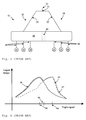
- Fig. 1 illustrates a schematic view of a prior art intake system 10 for an internal combustion engine 12 having a plurality of cylinders 14.
- the prior art intake system 10 system comprises two intake portions 16, 18, wherein each intake portion 16, 18 comprises a secondary pipe 20, 22 connected to a primary chamber 24, 26.
- Each primary chamber 24, 26 is connected to at least one primary pipe 28, 30 adapted to communicate with at least one cylinder 14.
- the prior art intake system 10 supplies an internal combustion engine 12 with a fluid, comprising either air or a mixture of air and fuel depending on the type of internal combustion engine 12 being supplied with the fluid.
- the fluid supply is generally regulated by an admission valve located in an intake opening 32 of the intake system; the admission valve is generally associated with an engine throttle, and at least one cylinder valve 34 for each cylinder 14 of the internal combustion engine.
- the cylinder valves 34 are not illustrated in the figures. However, a cylinder valve 34 is generally located in the vicinity of a cylinder 14 and the cylinder valve 34 is generally attached in a cylinder head of an internal combustion engine. Due to temporal regulation of the opening of the valves 34, pressure waves may build up in the prior art intake system 10.
- Such enhancement derives from the fact that the aforementioned negative pressure wave propagating from a first primary chamber 24 is able to rebound towards the first primary chamber 24 as a positive pressure wave at the same time as a negative pressure wave rebounds towards the second primary chamber 26.
- a standing wave is susceptible to being built up, having a pressure node at an intersection of the two secondary pipes 20, 22.
- a natural frequency of the pressure waves is stipulated by the geometry of the intake system 10.
- the internal combustion engine 12 connected to the prior art intake system 10 is generally adapted to provide a plurality of engine speeds and the engine torque obtained from the internal combustion engine generally varies with the engine speed.
- Fig. 2 depicts a graph 36, illustrating the engine torque as a function of the engine speed for a typical internal combustion engine utilizing a prior art intake system, for example the one illustrated in Fig. 1.
- a maximum engine torque is obtainable at a certain engine speed; the maximum torque engine speed is indicated by 38 in Fig. 2.
- the engine speed, for which a maximum torque is obtainable corresponds to the natural frequency of the prior art intake system 10, since the internal combustion engine 12 will be provided with a maximum of fluid at this engine speed.
- an engine torque characteristic as illustrated by graph 36 in Fig. 4.
- a certain threshold value for example a value corresponding to the engine speed indicated by numeral 46 in Fig. 4
- the barrier 45 is removed and the engine torque characteristics will switch to the characteristics illustrated by graph 42.
- an engine torque characteristic is obtainable which for all engine speeds is the higher value of the two characteristics indicated by graphs 36 and 42.
- An example of such a characteristic is illustrated by graph 47 in Fig. 4.
- the barrier effect can be achieved by inserting a valve in the common chamber 40, or plenum, and the valve is open or closed, based on the actual engine speed of the internal combustion engine.
- the intake system 10 does not involve the aforementioned downsides of prior art intake systems and the invention will hereinbelow be exemplified by embodiments.
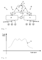
- Fig. 5 illustrates a schematic view of an embodiment of an intake system 10 according to the invention for an internal combustion engine 12 having a plurality of cylinders 14.
- the internal combustion engine 12 illustrated in Fig. 5 has six cylinders 14, but the intake system according to the invention may be adapted to cooperate with an internal combustion engine 12 having more or less than six cylinders 14, as long as the internal combustion engine is equipped with at least two cylinders 14.
- the system comprises a plurality of intake portions 16, 18, wherein each intake portion 16, 18 comprises a secondary pipe 20, 22 connected to a primary chamber 24, 26.
- Fig. 5 illustrates an embodiment of the invention comprising only two intake portions 16, 18 but other embodiments of the invention may comprise three or more intake portions. In the embodiments of the invention illustrated in herein, only intake systems with two intake portions are illustrated since two intake portions suffice to explain the principles of the invention.
- a largest cross-sectional area of the primary chamber 24, 26 is substantially greater, for example at least 1.2, preferably 1.4, times greater than an average cross-sectional area of the associated secondary pipe 20, 22.
- Each primary chamber 24, 26 is connected to its respective primary pipe 28, 30 adapted to communicate with the cylinders 14.
- the two intake portions 16, 18 are in fluid communication via a first fluid communication means 48 comprising a first passage 50 (not shown).
- the first fluid communication means 48 extends between the respective primary chamber 24, 26.
- the first fluid communication means 48 exhibits a substantially constant cross-section for each axial location in said first fluid communication means 48. In other words, the means 48 contains no active parts.
- the engine torque characteristics obtainable for an internal combustion engine utilizing an intake system 10 according to the Fig. 5 embodiment is illustrated by graph 52 in Fig. 6. Included in Fig. 6 are further the graphs of the prior art intake systems illustrated in Figs. 1 and 3, respectively.
- the engine torque value of an internal combustion engine 12 being equipped with the Fig. 5 intake system 10 is susceptible to having a wider range of engine speeds than either of the two engine torque characteristics of prior art, indicated by reference numerals 36 and 42, respectively.
- prior art teaches that the engine torque characteristics corresponding to the graphs 36 and 42 may be combined by utilizing a valve system in conjunction with a regulating system.
- the intake system 10 of the Fig. 5 embodiment of the invention will in fact result in an equally wide range of engine speeds at which high engine torques are obtainable, even though the intake system 10 according to the invention is a passive system, i.e. it does not contain any moving parts nor any regulating means.
- the reason for obtaining the wide engine torque range utilizing an intake system 10 of the invention emanates, as previously described, from the fact that the first and second primary chambers 16, 18 will communicate partially through the first fluid communication means 48, which in turn will allow for two natural frequencies to exist in parallel.
- a smallest cross-sectional area of the first fluid communication means 48 is preferably in a range of 0.1-50 %, more preferably 1-25 %, most preferably 4-16 %, of the largest cross-sectional area of the primary chambers 24, 26 in fluid communication.
- a length of the secondary pipe 20 of an intake portion 16 in fluid communication with another intake portion 18 is preferably in a range of 50- 200 %, more preferably 50 - 150 %, most preferably 70 -130 %, of the shortest of the primary pipes 28 of the intake portion 16.
- a length of a primary pipe 28 is defined as the distance run along the primary pipe 28 from a primary chamber 24 with which the primary pipe 28 is associated, to the cylinder valves 34 corresponding to the primary pipe 28.
- the length of the primary pipe 28 may in some applications in fact include a length of a passage in e.g. a cylinder head (not shown) in which the cylinder valves 34 are located.
- the length of a secondary pipe 20, 22 is defined as the distance run from a primary chamber 24 with which the secondary pipe 20 is associated, along the secondary pipe 20, 22 until the secondary pipe terminates, which may for example be in a Y-connection 31, as illustrated in Fig. 5, or in a secondary plenum, as will be discussed below.
- the aforementioned definitions of the lengths of the primary and secondary pipes, respectively, will hereinafter apply.
- Fig. 7 illustrates a further embodiment of an intake system 10 of the invention, wherein two of the intake portions 16, 18 are in fluid communication via a second fluid communication means 54 comprising a second passage 56.
- the second fluid communication means 54 extends between the secondary pipes 20, 22 wherein the second fluid communication means 54 exhibits a substantially constant cross-section for each axial location in the second fluid communication means 54.
- Fig. 8 discloses a graph 56 illustrating an engine torque characteristic which is obtainable when utilizing the Fig. 7 embodiment of the intake system 10 according to the invention in an internal combustion engine 12.
- a third natural frequency of the pressure waves in the intake system 10 is obtained, resulting in a third torque peak in the engine torque characteristics.
- an even wider interval of engine speeds is obtained, for which a high engine torque is attainable, while still utilizing a passive inlet system 10.
- the smallest cross-sectional area of the second fluid communication means 54 is preferably in a range of 0.01-50 %, more preferably 0.2-25 %, most preferably 1-10 %, of the largest cross-sectional area of the secondary pipes 20, 22 in fluid communication.
- Each of the secondary pipes 20, 22 has a first end 58, 60 associated with the respective primary chamber 24, 26 and the second fluid communication means 54 is preferably located at fluid communication distances 62, 64 from the first end 58, 60 of each secondary pipe 20, 22 associated with the second fluid communication means 54.
- Each fluid communication distance 62, 64 is preferably 10- 90 %, more preferably 20- 80 %, most preferably 30- 60 %, of the length of the corresponding secondary pipe 20, 22.
- all fluid communication distances 62, 64 are substantially equal.
- all secondary pipes 20, 22 preferably have substantially equal length and may preferably have substantially equal largest cross-sectional areas.
- each secondary pipe 20, 22 preferably has a second end 66, 68 remote from the respective primary chamber 24, 26 and each second end 66, 68 is adapted to form a portion of a Y-connection 31.
- each second end 66, 68 of the respective secondary pipe 20, 22 may instead be connected to a secondary plenum 70.
- the secondary plenum 70 is common for all the secondary pipes 20, 22.
- the primary chambers 24, 26 may be a unitary component, internally separated by one or more walls 72.
- the wall 72 is provided with the first fluid communication means 48 which, in the Fig. 10 implementation of the first fluid communication means 48, is constituted by an opening.
- the secondary pipes 20, 22 may in some embodiments of the invention be a unitary component, internally separated by one or more walls 74.
- the wall 74 is provided with the second fluid communication means 54.
- one of the primary chambers 24 is a separate component, connected to of the other chamber 26 by a first connection 76 provided with the first fluid communication means 48.
- at least one of the secondary pipes 20 may in some embodiments of the invention be a separate component, connected to at least one of said other secondary pipes 22 by a second connection 78 provided with the second fluid communication means 54.
- the first fluid communication means 48 may simply be an opening in the first connection 76 and a similar solution may in some applications be provided for a possible second connection 78.
- the second connection 78 merely serves as an example, either the first or the second passage 76, 78 may be internally provided with a wall 80 or a constriction of the actual passage 76, 78 and the wall 80 may in turn be provided with a passage opening 82.
- the second fluid communication means 54 in the embodiment of the invention illustrated in Fig. 11 comprises three internal portions wherein the cross-section of each internal portion differs from the adjacent internal portion or portions.
- This specific embodiment of the intake system 10 is an air intake system intended to be used in conjunction with a six-cylinder-in-line type internal combustion engine 12 having a fuel injection system.
- the intake system 10 is constituted by two intake portions 16, 18 wherein the primary chamber 24, 26 of each portion 16, 18 is provided with three primary pipes 28, 30. Thus a total of six primary pipes, one for each cylinder 14 is provided in the intake system 10.
- the primary chambers 24, 26 are a unitary component separated by a wall 72 provided with a first fluid communication means 48, in this specific embodiment constituted by an opening in the chamber wall 72.
- Each primary chamber is 24, 26 connected to a secondary pipe 20, 22.
- the secondary pipes 20, 22 are separate tubes, extending from the respective primary chambers 24, 26 to a Y-connection 31.
- connection pipe Halfway up each secondary pipe 20, 22 a connection in form of a connection pipe having the same cross-sectional area as each secondary pipe 20, 22 is provided, allowing a fluid communication between the secondary pipes.
- the connection pipe is provided with a wall 80 having a passage opening 82.
- the primary pipes 28, 30 are conical, each primary pipe having an inner diameter of 46 mm at the primary chamber 24, 26 and 33 mm at the location of the cylinder valve 34.
- Each primary pipe 28, 30 has a length of 290 mm.
- Each secondary pipe 20, 22 has a constant inner diameter of 62 mm and the length of each secondary pipe is 310 mm.
- the total length of the unitary component comprising the primary chambers 24, 26 is 550 mm, thus each primary chamber 24, 26 has an internal length of 275 mm.
- Each primary chamber 24, 26 has an equivalent diameter, i.e. the diameter of a circle having equal cross-sectional area as the primary chamber 24, 26, of 75 mm.
- the first fluid communication means 48 is constituted by a cylindrical opening in the chamber wall 72 and the diameter of the opening is 15 mm.
- the passage opening 82 in the connection pipe has a cylindrical passage opening having a diameter of 15.5 mm.
- the total volume of the intake system 10 is 7.7 litres.
- the first fluid communication means 48 may comprise a plurality of passages 50 of equal or different shape.
- the first fluid communication means 48 may comprise at least two walls 72 separating a first and a second primary chamber 24, 26 which are a unitary component, wherein each wall 72 is provided with at least one opening.
Landscapes
- Engineering & Computer Science (AREA)
- Chemical & Material Sciences (AREA)
- Combustion & Propulsion (AREA)
- Mechanical Engineering (AREA)
- General Engineering & Computer Science (AREA)
- Characterised By The Charging Evacuation (AREA)
Abstract
Description
- The present invention relates to intake systems of the type used in internal combustion engine having a plurality of cylinders.
- The invention further relates to a method of method of supplying an internal combustion engine, having a plurality of cylinders and a plurality of possible engine speeds, with a fluid comprising either air or a mixture of fuel and air
- An internal combustion engine is generally provided with either a fuel injection system or a carburetter system. In either case, each cylinder of the engine is provided with fuel and air; in the injection system, fuel and air are supplied separately; and in the carburetter system, a mixture of fuel and air is supplied to each cylinder.
- At least one valve for regulating the intake of a fluid comprising either air or the mixture of fuel and air is provided between each cylinder and the intake system. Furthermore, an inlet end of the intake system which is remote from the cylinders is preferably associated with a valve for regulating the supply of fluid to the intake system, i.e. a throttle valve.
- Due to the distance between the inlet end and the cylinder valves, and temporal regulations of the cylinder valves, the fluid has a tendency to pulsate in the intake system, i.e. pressure waves may build up in the intake system. Depending on the geometry of the intake system, a natural frequency of the pressure waves in the intake system is obtained at which natural frequency the cylinders are provided with an optimum fluid supply, resulting in an optimum torque output of the internal combustion engine. Prior art teaches tuning of the intake system, by for example varying lengths of members of the intake system, in order to obtain an optimum torque at a desired engine speed.
- However, the optimum torque will only occur at one engine speed associated with the natural frequency of the pressure wave in the intake system and the engine torque will consequently be lower for engine speeds not associated with the aforesaid natural frequency, i.e. corresponding to the optimum engine speed. Thus, for an engine speed other than the optimal for a specific intake system, the engine torque obtained is lower than what is achievable by the engine. Internal combustion engines of this kind are sometimes referred to as internal combustion engines having only one engine torque peak.
- In order to avoid the one peak behaviour of an internal combustion engine, prior art teaches the use of an intake system which comprises two portions, a first and a second intake portion, wherein the first and second portions are associated with a first and second set of cylinders, respectively. The first and second intake portions are in fluid communication by at least one first connection, wherein the first connection is provided with a first valve. Depending on the actual engine speed, the first valve is open or closed. The position of the first valve, i.e. open or closed, will influence the natural frequency of the pressure waves in the intake system and thus two natural frequencies of the intake system are obtainable: one when the first valve is closed and one when the first valve is open. Thus, the engine speed at which the aforementioned engine torque peak is obtained can be altered, and hence a high engine torque is obtainable for at least two engine speeds. This feature will in fact widen the interval of engine speeds, at which a high engine torque is obtained.
- By introducing a second connection with a second valve between the first and second intake portions, a third natural frequency is obtainable, thus making the interval of high torque engine speeds even wider.
- However, one drawback of introducing several natural frequencies in the intake system by utilizing the aforementioned technique is that a regulating system is required which regulates the valves in the intake system depending on the engine speed. This regulating system generally comprises the valves themselves as well as related mechanical and/or electrical arrangements. This implies an increase in the cost of the engine, as well as increasing the lead time for manufacturing the inlet system and thus the internal combustion engine. Furthermore, the aforementioned system generally requires software for regulating the valves and the software and the regulating system has to be thoroughly calibrated in order to function properly.
- An object of the invention is to provide an intake system for an internal combustion engine which, in conjunction with an internal combustion engine, provides a wide interval of high torque engine speeds but does not present the disadvantages of prior art intake systems.
- This object is achieved by a fluid charging arrangement as claimed in appended
claim 1. - Thus, the invention relates to an intake system for an internal combustion engine having a plurality of cylinders. The system comprises a plurality of intake portions wherein each intake portion comprises an associated secondary pipe connected to an associated primary chamber. A largest cross-sectional area of the primary chamber is substantially greater than an average cross-sectional area of the associated secondary pipe. Each primary chamber is connected to at least one primary pipe adapted to communicate with at least one cylinder. At least two of the intake portions are in fluid communication via a first fluid communication means comprising at least one first passage. The first fluid communication means extends between the respective primary chambers. According to the invention, the first fluid communication means exhibits a substantially constant cross-section for each axial location in the first fluid communication means.
- As used herein, by the expression "cross-sectional area" of a member it is meant the area of an internal cross-section, which cross-section is perpendicular to the longitudinal extension of the member.
- Furthermore, as used herein, by the expression "substantially greater than" it is meant that a largest cross-sectional area of the primary chamber is at least 1.2, preferably at least 1.4, times larger than the average cross-sectional area of the associated secondary pipe.
- Further, as used herein, by the expression "substantially constant cross-section" it is meant that the first communication means is a permanent means, not adapted to substantially vary any of the cross-sections of the first fluid communication means, for example an intermittently actuated valve is not to be considered as providing substantially constant cross-section. Thus, the first fluid communication means does not comprise any valves or similar means for regulating any cross-sectional area of the first fluid communication means. Thus, the first fluid communication means of the invention may also be referred to as a passive or a fixed fluid communication means.
- Using an intake system pursuant to the invention in an internal combustion engine will result in an engine where a wide engine speed interval with a high engine torque is obtainable, but where disadvantages of prior art systems, e.g. the use of valves and corresponding control systems, are avoided. Providing at least one passage between at least two primary chambers may introduce a second natural frequency of the pressure waves of the fluid in the inlet, in addition to the original first natural frequency of the pressure waves which is always present in a conduit system, and the second natural frequency may preferably be adjusted so as to be located in an interval corresponding to relevant engine speeds of the internal combustion engine, i.e. engine speeds at which the engine is particularly intended to operate.
- Since the at least one first passage, according to the invention, is passive, i.e. not adapted to change any cross-sectional area in the passage, the need for devices such as valves and related mechanical and/or electrical arrangements is omitted. Prior art inlet systems which are adapted to have a wide engine torque interval generally require the aforementioned devices in order to function properly. Furthermore, prior art inlet systems generally require control equipment comprising a control algorithm which has to be calibrated in order to obtain a suitable value of the second natural frequency of the inlet system, as well as a desired engine torque. In the inlet system according to the present invention, no calibration or tuning of each inlet system is required. Instead, a shape of the first fluid communication means is determined in the design phase of the inlet system and each inlet system of the corresponding design is later provided with a first fluid communication means with the predetermined passage characteristics. This significantly simplifies the manufacturing, mounting and tuning of the intake system.
- According to one embodiment of the invention, a smallest cross-sectional area of the first fluid communication means is in a range of 0.1-50 %, preferably 1-25 %, more preferably 4-16 %, of a largest cross-sectional area of the primary chambers in fluid communication. By arranging the smallest cross-sectional area of the first fluid communication means in the aforesaid area intervals, the fluids in each intake portion will partially communicate, resulting in a second natural frequency of the pressure waves. However, since the fluids in each intake portion will only communicate partially, the original first natural frequency, i.e. the natural frequency of the intake system without the first fluid communication means connecting at least two chambers, will remain in the intake system. In fact, for intake systems wherein the cross-sectional area of the first fluid communication means is below 100 % of the largest cross-sectional area of the primary chambers in fluid communication, the first and second natural frequencies may simultaneously exist due to a partial communication between the intake portions, although the aforementioned area intervals are preferable. However, a partial fluid communication may also be achieved by other means than adjusting the cross-sectional area of the first fluid communication means. For example, at least one of the first chambers in fluid communication may be internally equipped with protrusions, e.g. ribs, which may influence the fluid communication between the first chambers in fluid communication.
- According to a further embodiment of the invention, a length of the secondary pipe of an intake portion in fluid communication with another intake portion is in a range of 50- 200 %, preferably 50 - 150 %, more preferably 70-130 %, of the shortest of the least one primary pipe of the intake portion. By arranging the length of the secondary pipe in one of the aforementioned ranges, eligible first and second natural frequencies are obtainable.
- According to another embodiment of the invention, at least two of the intake portions are in fluid communication via a second fluid communication means comprising at least one second passage. The second fluid communication means extends between the respective secondary pipes wherein said second fluid communication means exhibits a substantially constant cross-section for each axial location in said second fluid communication means. By arranging a fluid communication between at least two secondary pipes, a third natural frequency of the aforementioned pressure waves is obtainable. This enables an even wider range of engine speeds at which a high engine torque can be attained.
- According to another embodiment of the invention, a smallest cross-sectional area of the second fluid communication means is in a range of 0.01-50 %, preferably 0.2-25 %, more preferably 1-10 %, of a largest cross-sectional area of the secondary pipes in fluid communication. Analogical to the previously disclosed reasoning regarding the cross-sectional area of the first fluid communication means, the smallest cross-sectional area of the second fluid communication means is preferably selected to be sufficiently large in order to attain a third natural frequency, but also sufficiently small in order not to erase any one of the first and second natural frequencies.
- According to a further embodiment of the invention, each secondary pipe has a first end associated with the respective primary chamber. The second fluid communication means is located at fluid communication distances from the first end of each secondary pipe, associated with said second fluid communication means. Each fluid communication distance is 10- 90 %, preferably 20- 80 %, more preferably 30- 60 %, of the length of the corresponding secondary pipe. By arranging the length of the secondary pipe in one of the aforementioned distance ranges, an eligible third natural frequency, in relation to the first and second natural frequencies, is obtainable. Furthermore, all fluid communication distances are preferably substantially equal.
- According to another embodiment of the invention, the secondary pipes further have substantially equal length in order to obtain an appropriate build up of pressure waves in the intake system. In addition to, or instead of, having substantially equal length, the secondary pipes may preferably have substantially equal cross-sectional areas.
- According to another embodiment of the invention, each secondary pipe has a second end remote from the respective primary chamber and each second end is adapted to form a branch of a Y-connection. Furthermore, one opening of the Y-connection may be adapted to be associated with a throttle valve of an internal combustion engine.
- According to another embodiment of the invention, the aforementioned second end of each secondary pipe is connected to a secondary plenum, said secondary plenum being common for all the secondary pipes. Utilizing a secondary plenum as previously described, each intake portion is operable to receive a substantially mutually equal fluid supply which facilitates the build up of the three aforesaid natural frequencies. Furthermore, the shape of the secondary plenum may be shaped in order to obtain an appropriate behaviour of the pressure waves in the intake system.
- According to a further embodiment of the invention, the primary chambers are a unitary component, internally separated by at least one wall. The at least one wall is provided with the at least one first fluid communication means. Thus, a compact intake system is obtainable which requires little space in the internal combustion engine. Based on the same arguments, the secondary pipes may also be a unitary component, internally separated by at least one wall, said at least one wall being provided with said second fluid communication means.
- According to another embodiment of the invention, the at least one of the primary chambers is a separate component, connected to at least one of the other chambers by a first connection provided with the first fluid communication means. In some applications for the intake system, it may be preferred to separate at least one primary chamber of the intake system, for example due to packaging problems which may occur when mounting an intake system to an internal combustion engine. By providing the at least one separated primary chamber with a connection provided with the first fluid communication means, an objective of the present invention, i.e. to attain a first and second natural frequency in the intake system, is still achievable. Based on the same arguments, at least one of the secondary pipes may be a separate component, connected to at least one of the other secondary pipes by a second connection provided with said second fluid communication means.
- Another embodiment of the invention relates to an internal combustion engine comprising an intake system according to the present invention.
- A further embodiment of the invention relates to a vehicle comprising an internal combustion engine with the above mentioned features.
- A second object of the present invention is to provide a method of supplying an internal combustion engine, having a plurality of cylinders and a plurality of possible engine speeds, with a fluid comprising either air or a mixture of fuel and air, wherein a high engine torque is obtainable for a plurality of engine speeds.
- This second object is achieved by a distance adjustment method defined in the attached
claim 18. - The method according to the present invention relates to a method of supplying an internal combustion engine, having a plurality of cylinders and a plurality of possible engine speeds, with a fluid comprising either air or a mixture of fuel and air, comprising the steps of:
- Conveying the fluid through a intake system comprising at least two intake portions, each comprising a secondary pipe connected to a primary chamber, a largest cross-sectional area of the primary chamber being substantially greater than an average cross-sectional area of the associated secondary pipe, towards the cylinders of said engine, and
- allowing said fluid to flow through at least one first fluid communication means, connecting at least two of said primary chambers.
- According to a further embodiment of the method of the invention, the method further includes the first communication means having a substantially constant cross-sectional area irrespective of the engine speed of the internal combustion engine. Furthermore, the method of the invention may in a further embodiment comprise the cross-sectional area of the first communication means being in a range of 0.1-50 %, preferably 1-25 %, more preferably 4-16 %, of a largest cross-sectional area of the primary chambers in fluid communication.
- A further embodiment of the inventive method includes further steps of
- allowing said fluid to flow through a second fluid communication means, connecting at least two of said secondary pipes;
- allowing said fluid to flow through said second fluid communication means irrespective of said engine speed of said internal combustion engine.
- Another embodiment of the inventive method further comprises the second fluid communication means having a substantially constant cross-sectional area irrespective of said engine speed of said internal combustion engine. Furthermore, the method of the invention may in a further embodiment comprise the cross-sectional area of the second fluid communication means being in a range of 0.1-50 %, preferably 0.2-25 %, more preferably 1-10 %, of a largest cross-sectional area of the secondary pipes in fluid communication.
- The present invention will hereinafter be further explained by means of non-limiting examples with reference to the appended figures wherein;
- Fig. 1
- is a schematic view of a first prior art intake system;
- Fig. 2
- is a graph illustrating the engine torque as a function of engine speed for an internal combustion engine utilizing the Fig. 1 intake system;
- Fig. 3
- is a schematic view of a second prior art intake system;
- Fig. 4
- is a graph illustrating the engine torque as a function of engine speed for two prior art intake systems;
- Fig. 5
- is a schematic view of an intake system according to an embodiment of the invention;
- Fig. 6
- is a graph illustrating the engine torque as a function of engine speed for the Fig. 5 embodiment of the present invention;
- Fig. 7
- is a schematic view of an intake system according to another embodiment of the present invention;
- Fig. 8
- is a graph illustrating the engine torque as a function of engine speed for the Fig. 7 embodiment of the present invention;
- Fig. 9
- is a schematic view of an intake system according to a further embodiment of the present invention;
- Fig. 10
- is a cross-sectional view of an embodiment of the present invention; and
- Fig. 11
- is a cross-sectional view of a further embodiment of the present invention.
- The invention will, in the following, be exemplified by embodiments. It should however be realized that the embodiments are included in order to explain principles of the invention and not to limit the scope of the invention, defined by the appended claims.
- Fig. 1 illustrates a schematic view of a prior
art intake system 10 for an internal combustion engine 12 having a plurality ofcylinders 14. As may be gleaned from Fig. 1, the priorart intake system 10 system comprises twointake portions intake portion secondary pipe primary chamber primary chamber primary pipe cylinder 14. - The prior
art intake system 10 supplies an internal combustion engine 12 with a fluid, comprising either air or a mixture of air and fuel depending on the type of internal combustion engine 12 being supplied with the fluid. The fluid supply is generally regulated by an admission valve located in anintake opening 32 of the intake system; the admission valve is generally associated with an engine throttle, and at least one cylinder valve 34 for eachcylinder 14 of the internal combustion engine. The cylinder valves 34 are not illustrated in the figures. However, a cylinder valve 34 is generally located in the vicinity of acylinder 14 and the cylinder valve 34 is generally attached in a cylinder head of an internal combustion engine. Due to temporal regulation of the opening of the valves 34, pressure waves may build up in the priorart intake system 10. - This is due to the fact that when one of the
cylinders 14 is supplied with fluid during an intake stroke, fluid in theintake system 10 will progress towards the associated cylinder valve 34 due to a negative pressure at the valve 34. The negative pressure emanates from a pressure difference between thecylinder 14 and the associatedprimary pipe 28 of theprimary chamber 24; the pressure in thecylinder 14 is substantially smaller than the pressure in the associatedprimary pipe 28 during the intake stroke. Thus, a negative pressure wave propagates towards theintake opening 32 and later rebounds towards theprimary chamber 24, but as a positive pressure wave. The build up of pressure waves may be further enhanced in anintake system 10 comprising twoprimary chambers primary chamber 24 is able to rebound towards the firstprimary chamber 24 as a positive pressure wave at the same time as a negative pressure wave rebounds towards the secondprimary chamber 26. Thus, a standing wave is susceptible to being built up, having a pressure node at an intersection of the twosecondary pipes - A natural frequency of the pressure waves is stipulated by the geometry of the
intake system 10. The internal combustion engine 12 connected to the priorart intake system 10 is generally adapted to provide a plurality of engine speeds and the engine torque obtained from the internal combustion engine generally varies with the engine speed. - Fig. 2 depicts a
graph 36, illustrating the engine torque as a function of the engine speed for a typical internal combustion engine utilizing a prior art intake system, for example the one illustrated in Fig. 1. As may be gleaned from Fig. 2, a maximum engine torque is obtainable at a certain engine speed; the maximum torque engine speed is indicated by 38 in Fig. 2. The engine speed, for which a maximum torque is obtainable, corresponds to the natural frequency of the priorart intake system 10, since the internal combustion engine 12 will be provided with a maximum of fluid at this engine speed. - However, for other engine speeds than the optimum, an engine torque lower than the optimum is obtained. Consequently, the capacity of the internal combustion engine is not fully exploited for engine speeds other than the optimum one.
- In order to address this, some prior art intake system use the following insight: if the two
chambers common chamber 40 or a plenum, as illustrated in Fig. 3, a new characteristic of the engine torque as a function of engine speed is obtained; as denoted by 42 in the graphs in Fig. 4. A natural frequency of theintake system 10 is obtained, resulting in a new engine speed at which the engine torque reaches an optimum value, since pressure waves are allowed to propagate within thecommon chamber 40. This new maximum torque engine speed is indicated by 44 in Fig. 4. Prior art teaches that the two engine torque characteristics depicted bygraphs barrier 45 in thecommon chamber 40 which is present at low engine speeds, resulting in an engine torque characteristic as illustrated bygraph 36 in Fig. 4. When the engine speed exceeds a certain threshold value, for example a value corresponding to the engine speed indicated by numeral 46 in Fig. 4, thebarrier 45 is removed and the engine torque characteristics will switch to the characteristics illustrated bygraph 42. Thus, an engine torque characteristic is obtainable which for all engine speeds is the higher value of the two characteristics indicated bygraphs graph 47 in Fig. 4. - Prior art further teaches that the barrier effect can be achieved by inserting a valve in the
common chamber 40, or plenum, and the valve is open or closed, based on the actual engine speed of the internal combustion engine. - However, as previously stated, the disadvantages of using a valve is that this solution requires several components which may be expensive and cumbersome to install in the intake system. Furthermore, a regulating system is needed in order to open or close the valve based on the current engine speed. This regulating system requires tuning in order to function properly.
- The
intake system 10 according to the present invention does not involve the aforementioned downsides of prior art intake systems and the invention will hereinbelow be exemplified by embodiments. - Fig. 5 illustrates a schematic view of an embodiment of an
intake system 10 according to the invention for an internal combustion engine 12 having a plurality ofcylinders 14. The internal combustion engine 12 illustrated in Fig. 5 has sixcylinders 14, but the intake system according to the invention may be adapted to cooperate with an internal combustion engine 12 having more or less than sixcylinders 14, as long as the internal combustion engine is equipped with at least twocylinders 14. - As illustrated in Fig. 5, the system comprises a plurality of
intake portions intake portion secondary pipe primary chamber intake portions - A largest cross-sectional area of the
primary chamber secondary pipe primary chamber primary pipe cylinders 14. - As indicated in Fig. 5, the two
intake portions primary chamber means 48 contains no active parts. - The engine torque characteristics obtainable for an internal combustion engine utilizing an
intake system 10 according to the Fig. 5 embodiment is illustrated bygraph 52 in Fig. 6. Included in Fig. 6 are further the graphs of the prior art intake systems illustrated in Figs. 1 and 3, respectively. - As may be gleaned from Fig. 6, the engine torque value of an internal combustion engine 12 being equipped with the Fig. 5
intake system 10 is susceptible to having a wider range of engine speeds than either of the two engine torque characteristics of prior art, indicated byreference numerals graphs intake system 10 of the Fig. 5 embodiment of the invention will in fact result in an equally wide range of engine speeds at which high engine torques are obtainable, even though theintake system 10 according to the invention is a passive system, i.e. it does not contain any moving parts nor any regulating means. The reason for obtaining the wide engine torque range utilizing anintake system 10 of the invention emanates, as previously described, from the fact that the first and secondprimary chambers - A smallest cross-sectional area of the first fluid communication means 48 is preferably in a range of 0.1-50 %, more preferably 1-25 %, most preferably 4-16 %, of the largest cross-sectional area of the
primary chambers - A length of the
secondary pipe 20 of anintake portion 16 in fluid communication with anotherintake portion 18 is preferably in a range of 50- 200 %, more preferably 50 - 150 %, most preferably 70 -130 %, of the shortest of theprimary pipes 28 of theintake portion 16. As used herein, a length of aprimary pipe 28 is defined as the distance run along theprimary pipe 28 from aprimary chamber 24 with which theprimary pipe 28 is associated, to the cylinder valves 34 corresponding to theprimary pipe 28. As such, the length of theprimary pipe 28 may in some applications in fact include a length of a passage in e.g. a cylinder head (not shown) in which the cylinder valves 34 are located. Furthermore, as used herein, the length of asecondary pipe primary chamber 24 with which thesecondary pipe 20 is associated, along thesecondary pipe connection 31, as illustrated in Fig. 5, or in a secondary plenum, as will be discussed below.
In the description, the aforementioned definitions of the lengths of the primary and secondary pipes, respectively, will hereinafter apply. - Fig. 7 illustrates a further embodiment of an
intake system 10 of the invention, wherein two of theintake portions second passage 56. The second fluid communication means 54 extends between thesecondary pipes - Fig. 8 discloses a
graph 56 illustrating an engine torque characteristic which is obtainable when utilizing the Fig. 7 embodiment of theintake system 10 according to the invention in an internal combustion engine 12. As may be gleaned from Fig. 8, a third natural frequency of the pressure waves in theintake system 10 is obtained, resulting in a third torque peak in the engine torque characteristics. Thus, an even wider interval of engine speeds is obtained, for which a high engine torque is attainable, while still utilizing apassive inlet system 10. - The smallest cross-sectional area of the second fluid communication means 54 is preferably in a range of 0.01-50 %, more preferably 0.2-25 %, most preferably 1-10 %, of the largest cross-sectional area of the
secondary pipes - Each of the
secondary pipes first end primary chamber first end secondary pipe fluid communication distance secondary pipe - In a preferred embodiment of the invention, all fluid communication distances 62, 64 are substantially equal. Furthermore, all
secondary pipes - As illustrated in Fig. 7 each
secondary pipe second end primary chamber second end connection 31. - However, as illustrated in Fig. 9, each
second end secondary pipe secondary plenum 70. Thesecondary plenum 70 is common for all thesecondary pipes - As indicated in the embodiment of the invention illustrated in Fig. 10, the
primary chambers more walls 72. Thewall 72 is provided with the first fluid communication means 48 which, in the Fig. 10 implementation of the first fluid communication means 48, is constituted by an opening. Furthermore, thesecondary pipes more walls 74. Thewall 74 is provided with the second fluid communication means 54. - In another embodiment of the invention, illustrated in Fig. 11, one of the
primary chambers 24 is a separate component, connected to of theother chamber 26 by a first connection 76 provided with the first fluid communication means 48. Furthermore, at least one of thesecondary pipes 20 may in some embodiments of the invention be a separate component, connected to at least one of said othersecondary pipes 22 by asecond connection 78 provided with the second fluid communication means 54. - As illustrated in Fig. 11, the first fluid communication means 48 may simply be an opening in the first connection 76 and a similar solution may in some applications be provided for a possible
second connection 78. However, as further illustrated in Fig. 11, wherein thesecond connection 78 merely serves as an example, either the first or thesecond passage 76, 78 may be internally provided with awall 80 or a constriction of theactual passage 76, 78 and thewall 80 may in turn be provided with apassage opening 82. Thus, the second fluid communication means 54 in the embodiment of the invention illustrated in Fig. 11 comprises three internal portions wherein the cross-section of each internal portion differs from the adjacent internal portion or portions. - Finally, an example of an
actual intake system 10, pursuant to the teachings of the present invention is presented. It should be noted that the embodiment of the invention disclosed hereinbelow merely serves as an example and the dimensions presented below are simply one set of a plurality of different combinations of dimensions which all fall within the scope of the claims. - This specific embodiment of the
intake system 10 is an air intake system intended to be used in conjunction with a six-cylinder-in-line type internal combustion engine 12 having a fuel injection system. Theintake system 10 is constituted by twointake portions primary chamber portion primary pipes cylinder 14 is provided in theintake system 10. Theprimary chambers wall 72 provided with a first fluid communication means 48, in this specific embodiment constituted by an opening in thechamber wall 72. Each primary chamber is 24, 26 connected to asecondary pipe secondary pipes primary chambers connection 31. Halfway up eachsecondary pipe 20, 22 a connection in form of a connection pipe having the same cross-sectional area as eachsecondary pipe wall 80 having apassage opening 82. - In this specific embodiment of the intake system of the invention, the
primary pipes primary chamber primary pipe secondary pipe primary chambers primary chamber primary chamber primary chamber - The first fluid communication means 48 is constituted by a cylindrical opening in the
chamber wall 72 and the diameter of the opening is 15 mm. Thepassage opening 82 in the connection pipe has a cylindrical passage opening having a diameter of 15.5 mm. The total volume of theintake system 10 is 7.7 litres. - Further modifications of the invention within the scope of the claims are feasible. For instance, the first fluid communication means 48 may comprise a plurality of passages 50 of equal or different shape. Furthermore, the first fluid communication means 48 may comprise at least two
walls 72 separating a first and a secondprimary chamber wall 72 is provided with at least one opening.
Claims (23)
- An intake system (10) for an internal combustion engine (12) having a plurality of cylinders (14), said system comprising a plurality of intake portions (16, 18), wherein each intake portion (16, 18) comprises an associated secondary pipe (20, 22) connected to an associated primary chamber (24, 26), wherein a largest cross-sectional area of the primary chamber (24, 26) is substantially greater than an average cross-sectional area of the associated secondary pipe (20, 22), said primary chamber (24, 26) being connected to at least one primary pipe (28, 30) adapted to communicate with at least one of said plurality of cylinders (14), wherein at least two of said intake portions (16, 18) are in fluid communication via a first fluid communication means (48) comprising at least one first passage (50), said first fluid communication means (48) extending between the respective primary chambers (24, 26), characterized in that
said first fluid communication means (48) exhibits a substantially constant cross-section for each axial location in said first fluid communication means (48). - The intake system (10) according to claim 1, wherein a smallest cross-sectional area of said first fluid communication means (48) is in a range of 0.1-50 %, preferably 1-25 %, more preferably 4-16 %, of a largest cross-sectional area of the primary chambers (24, 26) in fluid communication.
- The intake system (10) according to any one of the preceding claims, wherein a length of said secondary pipe (20) of an intake portion (16) in fluid communication with another intake portion (18) is in a range of 50- 200 %, preferably 50 - 150 %, more preferably 70 - 130 %, of the shortest of the at least one primary pipe (28) of said intake portion (16).
- The intake system (10) according to any of the preceding claims, wherein at least two of said intake portions (16, 18) are in fluid communication via a second fluid communication means (54) comprising at least one second passage (56), said second fluid communication means (54) extending between the respective secondary pipes (20, 22) wherein said second fluid communication means (54) exhibits a substantially constant cross-section for each axial location in said second fluid communication means (54).
- The intake system (10) according to claim 4, wherein a smallest cross-sectional area of said second fluid communication means (54) is in a range of 0.01-50 %, preferably 0.2-25 %, more preferably 1-10 %, of a largest cross-sectional area of the secondary pipes (20, 22) in fluid communication.
- The intake system (10) according to claim 5, wherein each said secondary pipe (20, 22) has a first end (58, 60) associated with the respective primary chamber (24, 26) and said second fluid communication means (54) is located at fluid communication distances (62, 64) from the first end (58, 60) of each secondary pipe (20, 22), associated with said second fluid communication means (54), wherein each fluid communication distance (62, 64) is 10- 90 %, preferably 20- 80 %, more preferably 30- 60 %, of the length of the corresponding secondary pipe (20, 22).
- The intake system (10) according to claim 6, wherein all fluid communication distances (62, 64) are substantially equal.
- The intake system (10) according to any one of the preceding claims, wherein all secondary pipes (20, 22) have substantially equal length.
- The intake system (10) according to any one of the preceding claims, wherein all secondary pipes (20, 22) have substantially equal largest cross-sectional areas.
- The intake system (10) according to any of the preceding claims, wherein each said secondary pipe (20, 22) has a second end (66, 68) remote from the respective primary chamber (24, 26) and each second end (66, 68) is adapted to form a branch of a Y-connection (31).
- The intake system (10) according to any of the preceding claims, wherein each said secondary pipe (20, 22) has a second end (66, 68) remote from the respective primary chamber (24, 26) and each second end (66, 68) is connected to a secondary plenum (70), said secondary plenum (70) being common for all the secondary pipes (20, 22).
- The intake system (10) according to any one of the preceding claims, wherein said primary chambers (24, 26) are a unitary component, internally separated by at least one wall (72), said at least one wall (72) being provided with said first fluid communication means (48).
- The intake system (10) according to any one of claims 1 to 11, wherein at least one of said primary chambers (24) is a separate component, connected to at least one of said other chambers (26) by a first connection (76) provided with said first fluid communication means (48).
- The intake system (10) according to any one of the preceding claims, wherein said secondary pipes (20, 22) are a unitary component, internally separated by at least one wall (74), said at least one wall (74) being provided with said second fluid communication means (54).
- The intake system (10) according to any one of claims 1 to 13, wherein at least one of said secondary pipes (20) is a separate component, connected to at least one of said other secondary pipes (22) by a second connection (78) provided with said second fluid communication means (54).
- An internal combustion engine (12) comprising an intake system (10) according to any one of the preceding claims.
- A vehicle (80) comprising an internal combustion engine (12) according to claim 16.
- A method of supplying an internal combustion engine (12), having a plurality of cylinders (14) and a plurality of possible engine speeds, with a fluid comprising either air or a mixture of fuel and air, said method comprising the steps of:- conveying said fluid through an intake system (10) comprising at least two intake portions (16, 18), each comprising a secondary pipe (20, 22) connected to a primary chamber (24, 26), wherein a largest cross-sectional area of the primary chamber (24, 26) is substantially greater than an average cross-sectional area of the associated secondary pipe (20, 22), towards the cylinders (14) of said engine (12), and- allowing said fluid to flow through a first fluid communication means (48), connecting at least two of said primary chambers (24, 26);characterized by:- allowing said fluid to flow through said first fluid communication means (48) irrespective of said engine speed of said internal combustion engine (12).
- The method according to claim 18 in which- said first communication means (48) has a substantially constant cross-sectional area irrespective of said engine speed of said internal combustion engine (12).
- The method according to claim 19 in which- the cross-sectional area of said first communication means (48) is in a range of 0.1-50 %, preferably 1-25 %, more preferably 4-16 %, of a largest cross-sectional area of the primary chambers (24, 26) in fluid communication.
- The method according to any one of claims 18 to 20, further characterized by:- allowing said fluid to flow through a second fluid communication means (54) connecting at least two of said secondary pipes (20, 22), and- allowing said fluid to flow through said second fluid communication means (54) irrespective of said engine speed of said internal combustion engine (12).
- The method according to claim 18 wherein:- said second fluid communication means (54) has a substantially constant cross-sectional area irrespective of said engine speed of said internal combustion engine (12).
- The method according to claim 22 wherein- said second fluid communication means (54) is in a range of 0.1-50 %, preferably 0.2-25 %, more preferably 1-10 %, of a largest cross-sectional area of the secondary pipes (20, 22) in fluid communication.
Priority Applications (2)
| Application Number | Priority Date | Filing Date | Title |
|---|---|---|---|
| DE602006004440T DE602006004440D1 (en) | 2006-06-22 | 2006-06-22 | intake system |
| EP06115897A EP1870577B1 (en) | 2006-06-22 | 2006-06-22 | Intake system |
Applications Claiming Priority (1)
| Application Number | Priority Date | Filing Date | Title |
|---|---|---|---|
| EP06115897A EP1870577B1 (en) | 2006-06-22 | 2006-06-22 | Intake system |
Publications (2)
| Publication Number | Publication Date |
|---|---|
| EP1870577A1 true EP1870577A1 (en) | 2007-12-26 |
| EP1870577B1 EP1870577B1 (en) | 2008-12-24 |
Family
ID=37149820
Family Applications (1)
| Application Number | Title | Priority Date | Filing Date |
|---|---|---|---|
| EP06115897A Not-in-force EP1870577B1 (en) | 2006-06-22 | 2006-06-22 | Intake system |
Country Status (2)
| Country | Link |
|---|---|
| EP (1) | EP1870577B1 (en) |
| DE (1) | DE602006004440D1 (en) |
Citations (8)
| Publication number | Priority date | Publication date | Assignee | Title |
|---|---|---|---|---|
| JPS6069255A (en) * | 1983-09-14 | 1985-04-19 | Mazda Motor Corp | Air suction devide for v-type engine |
| JPS60169627A (en) * | 1984-02-14 | 1985-09-03 | Mazda Motor Corp | Suction device of engine |
| DE3530607A1 (en) * | 1984-08-27 | 1986-03-13 | Mazda Motor Corp., Hiroshima | INTAKE SYSTEM FOR A MULTI-CYLINDER INTERNAL COMBUSTION ENGINE |
| US4760819A (en) * | 1987-07-16 | 1988-08-02 | Vorum Peter C | Short pipe manifold for four-stroke engines |
| US5031598A (en) * | 1988-03-15 | 1991-07-16 | Mazda Motor Corporation | Intake system for multi-cylinder engine with supercharger |
| DE4231804A1 (en) * | 1991-10-01 | 1993-04-08 | Daimler Benz Ag | Intake for fuel injected IC- engine - has valve maintained in position to achieve targetted detuning of oscillations in intake air flow |
| EP0705965A1 (en) * | 1994-10-05 | 1996-04-10 | Dr.Ing.h.c. F. Porsche Aktiengesellschaft | Inlet pipe assembly for an internal combustion engine with two banks of cylinders |
| EP1277934A2 (en) * | 2001-07-17 | 2003-01-22 | Filterwerk Mann + Hummel Gmbh | Intake device for a multi-cylinder internal combustion engine |
-
2006
- 2006-06-22 EP EP06115897A patent/EP1870577B1/en not_active Not-in-force
- 2006-06-22 DE DE602006004440T patent/DE602006004440D1/en active Active
Patent Citations (8)
| Publication number | Priority date | Publication date | Assignee | Title |
|---|---|---|---|---|
| JPS6069255A (en) * | 1983-09-14 | 1985-04-19 | Mazda Motor Corp | Air suction devide for v-type engine |
| JPS60169627A (en) * | 1984-02-14 | 1985-09-03 | Mazda Motor Corp | Suction device of engine |
| DE3530607A1 (en) * | 1984-08-27 | 1986-03-13 | Mazda Motor Corp., Hiroshima | INTAKE SYSTEM FOR A MULTI-CYLINDER INTERNAL COMBUSTION ENGINE |
| US4760819A (en) * | 1987-07-16 | 1988-08-02 | Vorum Peter C | Short pipe manifold for four-stroke engines |
| US5031598A (en) * | 1988-03-15 | 1991-07-16 | Mazda Motor Corporation | Intake system for multi-cylinder engine with supercharger |
| DE4231804A1 (en) * | 1991-10-01 | 1993-04-08 | Daimler Benz Ag | Intake for fuel injected IC- engine - has valve maintained in position to achieve targetted detuning of oscillations in intake air flow |
| EP0705965A1 (en) * | 1994-10-05 | 1996-04-10 | Dr.Ing.h.c. F. Porsche Aktiengesellschaft | Inlet pipe assembly for an internal combustion engine with two banks of cylinders |
| EP1277934A2 (en) * | 2001-07-17 | 2003-01-22 | Filterwerk Mann + Hummel Gmbh | Intake device for a multi-cylinder internal combustion engine |
Also Published As
| Publication number | Publication date |
|---|---|
| EP1870577B1 (en) | 2008-12-24 |
| DE602006004440D1 (en) | 2009-02-05 |
Similar Documents
| Publication | Publication Date | Title |
|---|---|---|
| US7353791B2 (en) | Sound increase apparatus | |
| US10480537B2 (en) | Low-cost evacuator for an engine having tuned Venturi gaps | |
| US9121374B2 (en) | Wide-band damper for charge air lines of an internal combustion engine with turbocharger | |
| US7832205B2 (en) | Deflector style exhaust manifold | |
| US20080023262A1 (en) | Air-intake apparatus | |
| US20060236687A1 (en) | Deflector style exhaust manifold | |
| US10527009B2 (en) | Exhaust gas recirculating apparatus | |
| CN103629407A (en) | Flow control valve | |
| US8123498B2 (en) | Tunable choke tube for pulsation control device used with gas compressor | |
| US6912843B2 (en) | Exhaust system for a multi-cylinder internal combustion engine | |
| US10563668B2 (en) | Variable compressor | |
| EP0365016A2 (en) | Intake system for V-type engine | |
| US20190316613A1 (en) | Internal flow control using plasma actuators | |
| EP1870577A1 (en) | Intake system | |
| US6539907B2 (en) | Suction device used for internal combustion engine | |
| HU207375B (en) | Internal combustion piston engine | |
| US20120145109A1 (en) | Electromechanical valve for the pneumatic actuation of a device of an internal combustion engine | |
| US9657697B2 (en) | Intake duct | |
| JP4644245B2 (en) | Intake equipment for internal combustion engines | |
| US10954902B2 (en) | Internal combustion engine | |
| RU2415283C1 (en) | Internal combustion engine | |
| WO2006081077A2 (en) | Engine induction system | |
| KR20110061358A (en) | Natural Negative Pressure Variable Resonator Device | |
| JP2006194165A (en) | Intake device | |
| KR100527968B1 (en) | Variable EGR pipe for increase NVH in automobile |
Legal Events
| Date | Code | Title | Description |
|---|---|---|---|
| PUAI | Public reference made under article 153(3) epc to a published international application that has entered the european phase |
Free format text: ORIGINAL CODE: 0009012 |
|
| 17P | Request for examination filed |
Effective date: 20070531 |
|
| AK | Designated contracting states |
Kind code of ref document: A1 Designated state(s): AT BE BG CH CY CZ DE DK EE ES FI FR GB GR HU IE IS IT LI LT LU LV MC NL PL PT RO SE SI SK TR |
|
| AX | Request for extension of the european patent |
Extension state: AL BA HR MK YU |
|
| GRAP | Despatch of communication of intention to grant a patent |
Free format text: ORIGINAL CODE: EPIDOSNIGR1 |
|
| GRAS | Grant fee paid |
Free format text: ORIGINAL CODE: EPIDOSNIGR3 |
|
| AKX | Designation fees paid |
Designated state(s): DE GB SE |
|
| GRAA | (expected) grant |
Free format text: ORIGINAL CODE: 0009210 |
|
| AK | Designated contracting states |
Kind code of ref document: B1 Designated state(s): DE GB SE |
|
| REG | Reference to a national code |
Ref country code: GB Ref legal event code: FG4D |
|
| REF | Corresponds to: |
Ref document number: 602006004440 Country of ref document: DE Date of ref document: 20090205 Kind code of ref document: P |
|
| REG | Reference to a national code |
Ref country code: SE Ref legal event code: TRGR |
|
| PLBE | No opposition filed within time limit |
Free format text: ORIGINAL CODE: 0009261 |
|
| STAA | Information on the status of an ep patent application or granted ep patent |
Free format text: STATUS: NO OPPOSITION FILED WITHIN TIME LIMIT |
|
| 26N | No opposition filed |
Effective date: 20090925 |
|
| PGFP | Annual fee paid to national office [announced via postgrant information from national office to epo] |
Ref country code: SE Payment date: 20110419 Year of fee payment: 6 |
|
| PGFP | Annual fee paid to national office [announced via postgrant information from national office to epo] |
Ref country code: GB Payment date: 20110419 Year of fee payment: 6 |
|
| PGFP | Annual fee paid to national office [announced via postgrant information from national office to epo] |
Ref country code: DE Payment date: 20110510 Year of fee payment: 6 |
|
| REG | Reference to a national code |
Ref country code: GB Ref legal event code: 732E Free format text: REGISTERED BETWEEN 20111020 AND 20111025 |
|
| REG | Reference to a national code |
Ref country code: DE Ref legal event code: R082 Ref document number: 602006004440 Country of ref document: DE Representative=s name: LOUIS, POEHLAU, LOHRENTZ, DE |
|
| REG | Reference to a national code |
Ref country code: DE Ref legal event code: R082 Ref document number: 602006004440 Country of ref document: DE Representative=s name: LOUIS, POEHLAU, LOHRENTZ, DE Effective date: 20120207 Ref country code: DE Ref legal event code: R081 Ref document number: 602006004440 Country of ref document: DE Owner name: VOLVO CAR CORPORATION, SE Free format text: FORMER OWNER: FORD GLOBAL TECHNOLOGIES, LLC, DEARBORN, US Effective date: 20120207 |
|
| REG | Reference to a national code |
Ref country code: SE Ref legal event code: EUG |
|
| GBPC | Gb: european patent ceased through non-payment of renewal fee |
Effective date: 20120622 |
|
| PG25 | Lapsed in a contracting state [announced via postgrant information from national office to epo] |
Ref country code: SE Free format text: LAPSE BECAUSE OF NON-PAYMENT OF DUE FEES Effective date: 20120623 |
|
| REG | Reference to a national code |
Ref country code: DE Ref legal event code: R119 Ref document number: 602006004440 Country of ref document: DE Effective date: 20130101 |
|
| PG25 | Lapsed in a contracting state [announced via postgrant information from national office to epo] |
Ref country code: GB Free format text: LAPSE BECAUSE OF NON-PAYMENT OF DUE FEES Effective date: 20120622 Ref country code: DE Free format text: LAPSE BECAUSE OF NON-PAYMENT OF DUE FEES Effective date: 20130101 |