EP1870358A1 - Paper conveying apparatus and image forming apparatus using the paper conveying apparatus - Google Patents
Paper conveying apparatus and image forming apparatus using the paper conveying apparatus Download PDFInfo
- Publication number
- EP1870358A1 EP1870358A1 EP07109745A EP07109745A EP1870358A1 EP 1870358 A1 EP1870358 A1 EP 1870358A1 EP 07109745 A EP07109745 A EP 07109745A EP 07109745 A EP07109745 A EP 07109745A EP 1870358 A1 EP1870358 A1 EP 1870358A1
- Authority
- EP
- European Patent Office
- Prior art keywords
- paper
- conveying apparatus
- motor
- misalignment amount
- paper conveying
- Prior art date
- Legal status (The legal status is an assumption and is not a legal conclusion. Google has not performed a legal analysis and makes no representation as to the accuracy of the status listed.)
- Granted
Links
- 238000011144 upstream manufacturing Methods 0.000 claims abstract description 13
- 238000012546 transfer Methods 0.000 claims description 39
- 230000005284 excitation Effects 0.000 claims description 35
- 238000000034 method Methods 0.000 claims description 15
- 230000001133 acceleration Effects 0.000 claims description 8
- 238000012545 processing Methods 0.000 description 26
- 238000004364 calculation method Methods 0.000 description 5
- 230000007246 mechanism Effects 0.000 description 4
- 230000015654 memory Effects 0.000 description 4
- 230000008859 change Effects 0.000 description 3
- 238000004140 cleaning Methods 0.000 description 3
- 239000003086 colorant Substances 0.000 description 2
- 238000004590 computer program Methods 0.000 description 2
- 238000007796 conventional method Methods 0.000 description 2
- 238000011161 development Methods 0.000 description 2
- 238000012986 modification Methods 0.000 description 2
- 230000004048 modification Effects 0.000 description 2
- 238000003825 pressing Methods 0.000 description 2
- 230000015572 biosynthetic process Effects 0.000 description 1
- 230000003287 optical effect Effects 0.000 description 1
- 230000008569 process Effects 0.000 description 1
- 238000000926 separation method Methods 0.000 description 1
Images





Classifications
-
- B—PERFORMING OPERATIONS; TRANSPORTING
- B65—CONVEYING; PACKING; STORING; HANDLING THIN OR FILAMENTARY MATERIAL
- B65H—HANDLING THIN OR FILAMENTARY MATERIAL, e.g. SHEETS, WEBS, CABLES
- B65H9/00—Registering, e.g. orientating, articles; Devices therefor
- B65H9/16—Inclined tape, roller, or like article-forwarding side registers
-
- B—PERFORMING OPERATIONS; TRANSPORTING
- B65—CONVEYING; PACKING; STORING; HANDLING THIN OR FILAMENTARY MATERIAL
- B65H—HANDLING THIN OR FILAMENTARY MATERIAL, e.g. SHEETS, WEBS, CABLES
- B65H9/00—Registering, e.g. orientating, articles; Devices therefor
- B65H9/004—Deskewing sheet by abutting against a stop, i.e. producing a buckling of the sheet
-
- B—PERFORMING OPERATIONS; TRANSPORTING
- B65—CONVEYING; PACKING; STORING; HANDLING THIN OR FILAMENTARY MATERIAL
- B65H—HANDLING THIN OR FILAMENTARY MATERIAL, e.g. SHEETS, WEBS, CABLES
- B65H9/00—Registering, e.g. orientating, articles; Devices therefor
- B65H9/06—Movable stops or gauges, e.g. rising and falling front stops
-
- B—PERFORMING OPERATIONS; TRANSPORTING
- B65—CONVEYING; PACKING; STORING; HANDLING THIN OR FILAMENTARY MATERIAL
- B65H—HANDLING THIN OR FILAMENTARY MATERIAL, e.g. SHEETS, WEBS, CABLES
- B65H9/00—Registering, e.g. orientating, articles; Devices therefor
- B65H9/20—Assisting by photoelectric, sonic, or pneumatic indicators
-
- G—PHYSICS
- G03—PHOTOGRAPHY; CINEMATOGRAPHY; ANALOGOUS TECHNIQUES USING WAVES OTHER THAN OPTICAL WAVES; ELECTROGRAPHY; HOLOGRAPHY
- G03G—ELECTROGRAPHY; ELECTROPHOTOGRAPHY; MAGNETOGRAPHY
- G03G15/00—Apparatus for electrographic processes using a charge pattern
- G03G15/65—Apparatus which relate to the handling of copy material
- G03G15/6555—Handling of sheet copy material taking place in a specific part of the copy material feeding path
- G03G15/6558—Feeding path after the copy sheet preparation and up to the transfer point, e.g. registering; Deskewing; Correct timing of sheet feeding to the transfer point
- G03G15/6561—Feeding path after the copy sheet preparation and up to the transfer point, e.g. registering; Deskewing; Correct timing of sheet feeding to the transfer point for sheet registration
- G03G15/6564—Feeding path after the copy sheet preparation and up to the transfer point, e.g. registering; Deskewing; Correct timing of sheet feeding to the transfer point for sheet registration with correct timing of sheet feeding
-
- G—PHYSICS
- G03—PHOTOGRAPHY; CINEMATOGRAPHY; ANALOGOUS TECHNIQUES USING WAVES OTHER THAN OPTICAL WAVES; ELECTROGRAPHY; HOLOGRAPHY
- G03G—ELECTROGRAPHY; ELECTROPHOTOGRAPHY; MAGNETOGRAPHY
- G03G15/00—Apparatus for electrographic processes using a charge pattern
- G03G15/65—Apparatus which relate to the handling of copy material
- G03G15/6555—Handling of sheet copy material taking place in a specific part of the copy material feeding path
- G03G15/6558—Feeding path after the copy sheet preparation and up to the transfer point, e.g. registering; Deskewing; Correct timing of sheet feeding to the transfer point
- G03G15/6567—Feeding path after the copy sheet preparation and up to the transfer point, e.g. registering; Deskewing; Correct timing of sheet feeding to the transfer point for deskewing or aligning
-
- B—PERFORMING OPERATIONS; TRANSPORTING
- B65—CONVEYING; PACKING; STORING; HANDLING THIN OR FILAMENTARY MATERIAL
- B65H—HANDLING THIN OR FILAMENTARY MATERIAL, e.g. SHEETS, WEBS, CABLES
- B65H2801/00—Application field
- B65H2801/03—Image reproduction devices
- B65H2801/09—Single-function copy machines
-
- G—PHYSICS
- G03—PHOTOGRAPHY; CINEMATOGRAPHY; ANALOGOUS TECHNIQUES USING WAVES OTHER THAN OPTICAL WAVES; ELECTROGRAPHY; HOLOGRAPHY
- G03G—ELECTROGRAPHY; ELECTROPHOTOGRAPHY; MAGNETOGRAPHY
- G03G2215/00—Apparatus for electrophotographic processes
- G03G2215/00362—Apparatus for electrophotographic processes relating to the copy medium handling
- G03G2215/00535—Stable handling of copy medium
- G03G2215/00556—Control of copy medium feeding
- G03G2215/00561—Aligning or deskewing
-
- G—PHYSICS
- G03—PHOTOGRAPHY; CINEMATOGRAPHY; ANALOGOUS TECHNIQUES USING WAVES OTHER THAN OPTICAL WAVES; ELECTROGRAPHY; HOLOGRAPHY
- G03G—ELECTROGRAPHY; ELECTROPHOTOGRAPHY; MAGNETOGRAPHY
- G03G2215/00—Apparatus for electrophotographic processes
- G03G2215/00362—Apparatus for electrophotographic processes relating to the copy medium handling
- G03G2215/00535—Stable handling of copy medium
- G03G2215/00611—Detector details, e.g. optical detector
- G03G2215/00616—Optical detector
-
- G—PHYSICS
- G03—PHOTOGRAPHY; CINEMATOGRAPHY; ANALOGOUS TECHNIQUES USING WAVES OTHER THAN OPTICAL WAVES; ELECTROGRAPHY; HOLOGRAPHY
- G03G—ELECTROGRAPHY; ELECTROPHOTOGRAPHY; MAGNETOGRAPHY
- G03G2215/00—Apparatus for electrophotographic processes
- G03G2215/00362—Apparatus for electrophotographic processes relating to the copy medium handling
- G03G2215/00535—Stable handling of copy medium
- G03G2215/00717—Detection of physical properties
- G03G2215/00721—Detection of physical properties of sheet position
Definitions
- This patent specification generally describes a paper conveying apparatus and an image forming apparatus using the paper conveying apparatus.
- Conventional multicolor image forming apparatuses such as full color printers and spot color printers that produce multicolor images generally employ a tandem method for image forming.
- a tandem method a plurality of photoconductive drums are provided along a moving direction of an endless intermediate transfer belt.
- the photoconductive drums are charged and exposed to light to form electrostatic latent images thereon.
- the electrostatic latent images formed on the respective photoconductive drums are developed with toners of different colors to form toner images.
- the toner images are sequentially transferred to and are superimposed on the intermediate transfer belt.
- the superimposed toner image is conveyed by the intermediate transfer belt, is transferred onto paper at an image transfer position, and is then fixed on the paper.
- Such an image forming apparatus is generally configured to convey paper stocked in a paper feed unit one by one toward the image transfer position.
- resist rollers placed upstream of the image transfer position in a paper conveyance direction are known to be used. The resist rollers stop the paper, and are then driven to feed the paper toward the image transfer position in synchronization with conveyance of the toner image on the intermediate transfer belt.
- the leading edge of the paper is corrected at a nip between the resist rollers by contacting the leading edge of the paper against the nip between the resist rollers which are not driven, pushing the paper further, and bowing the paper.
- a gate means for positioning paper in a direction perpendicular to a paper conveyance direction is provided on a paper conveyance path.
- the gate means stops paper and corrects a paper position by contacting a leading edge of the paper against the gate means.
- resist rollers are provided just behind the gate means in the paper conveyance direction. After the gate means is opened, pushing paper that has a curled leading edge into a nip between the resist rollers is difficult and causes a problem such as paper misfeed and a crumpled leading edge. Also, when a leading edge portion of paper is deflected by contacting the gate means, pushing the deflected leading edge into the nip between the resist rollers is also difficult.
- a gate means is provided downstream of resist rollers in a paper conveyance direction. A leading edge of paper contacts the gate means and is positioned while the resist rollers are separated from each other. Then, the resist rollers contact each other to sandwich the paper therebetween, and the gate means is opened. The paper is timely conveyed toward an image transfer position by the resist rollers. A leading edge portion of paper positioned by the gate means is sandwiched between the resist rollers, and therefore, the paper is conveyed toward the image transfer position without causing misalignment of the paper after the paper is positioned.
- a slowed paper feed rate prevents high speed operation of an image forming apparatus.
- This specification describes at least one embodiment of a novel paper conveying apparatus that includes a gate member configured to close a paper conveyance path to position a leading edge of paper and to open the paper conveyance path after the positioning, resist rollers provided near the gate member on an upstream side in a paper conveyance direction to timely convey the paper downstream of the gate member in the paper conveyance direction, a detector provided near the gate member on a downstream side in the paper conveyance direction and configured to detect misalignment at an edge portion of the paper in a paper width direction perpendicular to the paper conveyance direction, and a moving member configured to move the resist rollers in the paper width direction by changing a drive mode and a rotation speed of a motor in accordance with a paper misalignment amount detected by the detector, the motor to cause the resist rollers to move.
- This specification further describes at least one embodiment of a novel image forming apparatus that employs the paper conveying apparatus.
- FIG. 7A a paper positioning operation of a paper conveying apparatus according to an embodiment of the present invention is described.
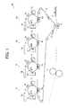
- FIG. 1 illustrates schematically a four-color image forming apparatus 100 as an image forming apparatus using a paper conveying apparatus 50 according to an embodiment of the present invention.
- the image forming apparatus 100 includes four image forming units 1a, 1b, 1c, and 1d provided along a moving direction of a transfer belt 10 indicated by an arrow A in FIG. 1.
- the image forming unit 1a includes a photoconductive drum 2a, a charging device 3a, an exposure device 4a, a development device 5a, a transfer device 6a, a cleaning device 7a, and so on.
- the photoconductive drum 2a operates as an image carrier.
- the image forming units 1b through 1d are configured in a similar way to the image forming unit 1a.
- the image forming units 1a through 1d are configured to form images of different colors, respectively.
- the image forming unit 1a forms a yellow image
- the image forming unit 1b forms a magenta image
- the image forming unit 1c forms a cyan image
- the image forming unit 1d forms a black image.
- the photoconductive drum 2a When receiving an instruction signal from a printer control unit, not shown, to start an image forming operation, the photoconductive drum 2a starts to rotate in a direction indicated by an arrow B in FIG. 1 and continues to rotate until the image forming operation is completed.
- the photoconductive drum 2a starts to rotate, high voltage is applied to the charging device 3a, and a surface of the photoconductive drum 2a is uniformly negatively charged.
- the toner image formed on the photoconductive drum 2a reaches a position of the transfer device 6a that operates as a primary transfer means, the toner image is transferred onto the transfer belt 10 rotating in the arrow A direction in FIG. 1 by high voltage applied to the transfer device 6a. After the toner image passes a transfer position of the toner image, a residual toner, which is not transferred and remains on the photoconductive drum 2a, is removed by the cleaning device 7a to prepare for a next image forming operation.
- the image forming unit 1b also performs an image forming operation in a similar way to the image forming unit 1a.
- a toner image formed on a photoconductive drum 2b is transferred onto the transfer belt 10 by high voltage applied to a transfer device 6b.
- the toner image formed on the photoconductive drum 2b is transferred onto the transfer belt 10 when the toner image which is formed by the image forming unit 1a and is transferred onto the transfer belt 10 reaches a position of the transfer device 6b. Consequently, the toner image formed by the image forming unit 1a is superimposed on the toner image formed by the image forming unit 1b on the transfer belt 10. Similarly, by superimposing toner images formed by the image forming units 1c and 1d on the transfer belt 10, a full color image is formed on the transfer belt 10.
- the full color image is conveyed to a paper transfer device 9 that operates as a secondary transfer means, and simultaneously, paper 8 is conveyed in a direction indicated by an arrow C in FIG. 1 from a paper feed unit, not shown, of the image forming apparatus 100 and reaches a position of the paper transfer device 9.
- the full color image on the transfer belt 10 is transferred onto the paper 8 by high voltage applied to the paper transfer device 9.
- the full color image on the paper 8 is melted and fixed on the paper 8.
- a residual toner which is not transferred and remains on the transfer belt 10, is removed by a belt cleaning mechanism 12.
- the paper conveying apparatus 50 which is provided upstream of the paper transfer device 9 in a paper conveyance direction, and a paper positioning operation thereof are now described in detail.
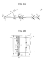
- FIG. 2A illustrates schematically the paper conveying apparatus 50 of FIG. 1 and FIG. 2B illustrates a top schematic view of the paper conveying apparatus 50.
- the paper conveying apparatus 50 of the present embodiment includes a gate means 13, resist rollers 14, conveyance rollers 15, a paper detector 16, timing rollers 17, conveyance rollers 24, and so on. A leading edge of paper contacts the gate means 13 to be positioned.
- the resist rollers 14 are provided near the gate means 13 on an upstream side in the paper conveyance direction. The upstream side in the paper conveyance direction is simply referred to as "upstream” hereinafter in the present specification.
- the conveyance rollers 15 are provided upstream of the resist rollers 14.
- the paper detector 16 for detecting paper misalignment is provided on a downstream side of the gate means 13 in the paper conveyance direction and between the gate means 13 and an image transfer position where an image is transferred onto the paper.
- the downstream side in the paper conveyance direction is simply referred to as "downstream” hereinafter in the present specification.
- the timing rollers 17 are provided downstream of the paper detector 16.
- the resist rollers 14 are capable of contacting (or pressing against) each other and being separated from each other by an opening and closing motor 30, which is described later.
- the conveyance rollers 15 are capable of contacting (or pressing against) each other and being separated from each other by a drive means not shown.
- the conveyance rollers 24 are provided upstream of the conveyance rollers 15.
- the resist rollers 14, the conveyance rollers 15, the timing rollers 17, and the conveyance rollers 24 rotate as indicated by arrows D in FIG. 2A, respectively.
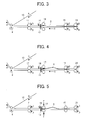
- FIGS. 3 through 10 illustrate a paper positioning operation of the paper conveying apparatus 50.
- Paper 8 fed from the paper feed unit, not shown, is conveyed by the conveyance rollers 24, the conveyance rollers 15, and so on, in a direction indicated by an arrow C in FIG. 3 toward the gate means 13 at a specified speed.
- the resist rollers 14 are separated from each other and the gate means 13 is closed before the paper 8 reaches the resist rollers 14.
- the paper 8 is further conveyed and a leading edge of the paper 8 contacts the gate means 13. While the leading edge of the paper 8 is contacting the gate means 13, a trailing edge of the paper 8 is further conveyed downstream by the conveyance rollers 15 to bow the paper 8 (FIG. 4).
- the gate means 13 is opened in a direction indicated by an arrow F in FIG. 6 to be retracted from a paper conveyance path.
- the conveyance rollers 15 are separated from each other as indicated by arrows G in FIG. 6 so that the paper 8 is straightened (FIG. 5). In other words, paper misalignment on an upstream side of the resist rollers 14 is also corrected.
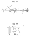
- the paper 8 is timely conveyed by the resist rollers 14 at a specified speed in a direction indicated by an arrow C in FIG. 7A so that a leading edge of a toner image conveyed on the transfer belt 10 in the transfer belt rotation direction coincides with a predetermined position on a leading edge portion of the paper 8 in the paper conveyance direction (FIGS. 7A and 7B).
- the resist rollers 14 are fixed to a unit frame 19.
- the unit frame 19 is continuously pressed against a cam 21 by a spring 20.
- a vertical drive motor 33 moves the unit frame 19 by rotating the cam 21.
- Paper misalignment in a direction perpendicular to the paper conveyance direction (a direction indicated by an arrow K in FIG. 8B) is corrected by rotating the cam 21 according to a paper misalignment amount d between a position of an edge portion of the paper 8 and a paper feed reference position P.
- the paper misalignment amount d is measured with the paper detector 16 provided near the unit frame 19 on a downstream side (FIGS. 8A and 8B).
- the resist rollers 14 are separated from each other as indicated by arrows I in FIG. 9A to prepare for positioning a next sheet of paper (FIG. 9A).
- the unit frame 19 returns to a home position by reversely rotating the cam 21 to respond to vertical misalignment of the next sheet of paper.
- the conveyance rollers 15 press against each other as indicated by arrows H in FIG. 9A to prepare for conveying the next sheet of paper (FIGS. 9A and 9B).
- the gate means 13 When the trailing edge of the paper 8 has passed the gate means 13, the gate means 13 is closed in a direction indicated by an arrow J in FIG. 10 to block the paper conveyance path and waits for the next sheet of paper. (FIG. 10)
- FIG. 11A illustrates a state in which the unit frame 19 is positioned at the home position
- FIG. 11B illustrates a state in which the cam 21 is rotated in a counterclockwise direction by 90 degrees
- FIG. 11C illustrates a state in which the cam 21 is rotated in a clockwise direction by 90 degrees
- a sensor plate 22 is connected to a motor axis 25 of the vertical drive motor 33.
- a home position of the vertical drive motor 33 is controlled by setting the home position of the vertical drive motor 33 to a position of the vertical drive motor 33 where the sensor plate 22 detects a position sensor 18.
- a stepper motor can be used for the vertical drive motor 33 and can be driven using a microstep method.
- FIGS. 12A and 12B illustrate a table of moving amount per step in 1-2 phase excitation mode.
- Using an acceleration table can further reduce a time period required for moving the unit frame 19.
- a distance between the timing rollers 17 and the paper detector 16 can also be reduced.
- the time period for moving the unit frame 19 can be reduced at a rotation speed identical to a rotation speed in 1-2 phase excitation mode by driving the stepper motor in, for example, 2-phase excitation mode.
- FIG. 13 illustrates a table of moving amount per step in 2-phase excitation mode.
- a DC motor may be used instead of a stepper motor.
- an image forming apparatus capable of high speed paper feeding can be achieved regardless of a distance between sheets of paper.
- FIG. 14 illustrates a drive mechanism to move the resist rollers 14, to rotate the resist rollers 14, and to move the unit frame 19 including the resist rollers 14.
- the opening and closing motor 30 drives the resist rollers 14 so that the resist rollers 14 contact each other and are separated from each other.
- a carrying motor 31 rotationally drives one of the resist rollers 14.
- a link mechanism 32 links the carrying motor 31 and the resist rollers 14.
- the vertical drive motor 33 moves the unit frame 19. As described above, a stepper motor is used for the vertical drive motor 33. By rotating the vertical drive motor 33, the cam 21 rotates according to the paper misalignment amount d to move the unit frame 19. Thus, paper misalignment in the direction perpendicular to the paper conveyance direction (the direction indicated by an arrow K in FIG. 9B) is to be corrected.
- FIGS. 15 through 19 are flow charts for specifically illustrating the operation described above. Although neither described above nor shown, an arithmetic and control unit such as a computer is used for control in the following operations.
- FIG. 15 is a flow chart illustrating an operation of changing a drive mode and a rotation speed of the vertical drive motor 33 according to the paper misalignment amount d.
- misalignment calculation is performed (Step 101).
- Step is abbreviated as S hereinafter.
- the paper misalignment amount d is determined by reading information of a CIS sensor (contact image sensor) (S102). Although the CIS sensor is used in the embodiment shown, the paper detector 16 may use any sensor other than the CIS sensor as well. Then, the paper misalignment amount d is checked to determine whether the paper misalignment amount d is equal to or less than a predetermined specified value (S103).
- the drive mode of the vertical drive motor 33 is changed to 2-phase excitation mode (S104).
- a rotation speed for 2-phase excitation mode is set (S105).
- a number of steps for 2-phase excitation mode is set (S106).
- Drive processing of the vertical drive motor 33 is performed to move the unit frame 19 (S107), and the series of processing ends.
- the drive mode of the vertical drive motor 33 is changed to 1-2 phase excitation mode (S108).
- a rotation speed for 1-2 phase excitation mode is set (S109).
- a number of steps for 1-2, phase excitation mode is set (S110).
- Drive processing of the vertical drive motor 33 is performed to move the unit frame 19 (S107), and the series of processing ends.
- FIG. 16 is a flow chart illustrating an operation of selecting to change the drive mode and the rotation speed of the vertical drive motor 33 according to the paper misalignment amount d.
- misalignment calculation is performed (S201).
- the paper misalignment amount d is determined by reading information of the CIS sensor (S202).
- whether to select to change the drive mode is determined (S203).
- the paper misalignment amount d is checked to determine whether the paper misalignment amount d is equal to or less than a specified value (S204).
- the drive mode of the vertical drive motor 33 is changed to 2-phase excitation mode (S205).
- a rotation speed for 2-phase excitation mode is set (S206).
- a number of steps for 2-phase excitation mode is set (S207).
- Drive processing of the vertical drive motor 33 is performed (S208), and the series of processing ends.
- S204 is skipped and the processing proceeds to S205.
- the drive mode of the vertical drive motor 33 is changed to 1-2 phase excitation mode (S209).
- a rotation speed for 1-2 phase excitation mode is set (S210).
- a number of steps for 1-2 phase excitation mode is set (S211).
- Drive processing of the vertical drive motor 33 is performed (S208), and the series of processing ends.
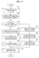
- FIG. 17 is a flow chart illustrating an operation of driving the vertical drive motor 33 by controlling the rotation speed according to an acceleration table for motor start-up.
- misalignment calculation is performed (S301).
- the paper misalignment amount d is determined by reading information of the CIS sensor (S302). Then, the paper misalignment amount d is checked to determine whether the paper misalignment amount d is equal to or less than a specified value (S303). When the paper misalignment amount d exceeds the specified value, the drive mode of the vertical drive motor 33 is changed to 2-phase excitation mode (S304).
- a rotation speed of the acceleration table for motor start-up is set (S305).
- a number of steps for 2-phase excitation mode is set (S306).
- Drive processing of the vertical drive motor 33 is performed to move the unit frame 19 (S307), and the series of processing ends.
- the drive mode of the vertical drive motor 33 is changed to 1-2 phase excitation mode (S308).
- the rotation speed of the acceleration table for motor start-up is set (S309).
- a number of steps for 1-2 phase excitation mode is set (S310).
- Drive processing of the vertical drive motor 33 is performed to move the unit frame 19 (S307), and the series of processing ends.
- FIG. 18 is a flow chart illustrating an operation of driving the vertical drive motor 33 by fixing the rotation speed at a self-starting frequency of the vertical drive motor 33 when the paper misalignment amount d is equal to or less than a predetermined value, and for driving the vertical drive motor 33 according to an acceleration table for motor start-up when the paper misalignment amount d is more than the predetermined value.
- misalignment calculation is performed (S401).
- the paper misalignment amount d is determined by reading information of the CIS sensor (S402). Then, the paper misalignment amount d is checked to determine whether the paper misalignment amount d is equal to or less than 0.5 mm (S403).
- the drive mode of the vertical drive motor 33 is changed to 2-phase excitation mode (S404).
- a rotation speed of the acceleration table for motor start-up is set (S405).
- a number of steps for 2-phase excitation mode is set (S406).
- Drive processing of the vertical drive motor 33 is performed to move the unit frame 19 (S407), and the series of processing ends.
- the drive mode of the vertical drive motor 33 is changed to 1-2 phase excitation mode (S408).
- the self-starting frequency of the vertical drive motor 33 is set (S409).
- a number of steps for 1-2 phase excitation mode is set (S410).
- Drive processing of the vertical drive motor 33 is performed to move the unit frame 19 (S407), and the series of processing ends.
- FIGS. 19A and 19B are a flow chart illustrating an operation of preventing the vertical drive motor 33 from driving when the paper misalignment amount d is equal to or less than a predetermined value.
- misalignment calculation is performed (S501).
- the paper misalignment amount d is determined by reading information of the CIS sensor (S502).
- the paper misalignment amount d is checked to determine whether the paper misalignment amount d is equal to or more than a predetermined non-movable value (S503).
- the paper misalignment amount d is checked to determine whether the paper misalignment amount d is equal to or less than a predetermined acceptable value (S504).
- the paper misalignment amount d is checked to determine whether the paper misalignment amount d is equal to or less than a predetermined specified value (S505).
- the drive mode of the vertical drive motor 33 is changed to 2-phase excitation mode (S506).
- a rotation speed for 2-phase excitation mode is set (S507).
- a number of steps for 2-phase excitation mode is set (S508).
- Drive processing of the vertical drive motor 33 is performed to move the unit frame 19 (S509), and the series of processing ends.
- any one of the above-described and other example features of the present invention may be embodied in the form of an apparatus, method, system, computer program and computer program product.
- the aforementioned methods may be embodied in the form of a system or device, including, but not limited to, any of the structure for performing the methodology illustrated in the drawings.
- any of the aforementioned methods may be embodied in the form of a program.
- the program may be stored on a computer readable medium and is adapted to perform any one of the aforementioned methods when run on a computer device (a device including a processor).
- a computer device a device including a processor
- the storage medium or computer readable medium is adapted to store information and is adapted to interact with a data processing facility or computer device to perform the method of any of the above mentioned embodiments.
- the storage medium may be a built-in medium installed inside a computer device main body or a removable medium arranged so that it can be separated from the computer device main body.
- Examples of the built-in medium include, but are not limited to, rewriteable non-volatile memories, such as ROMs and flash memories, and hard disks.
- the removable medium examples include, but are not limited to, optical storage media such as CD-ROMs and DVDs; magneto-optical storage media, such as MOs; magnetic storage media, including but not limited to floppy disks (trademark), cassette tapes, and removable hard disks; media with a built-in rewriteable non-volatile memory, Including but not limited to memory cards; and media with a built-in ROM, including but not limited to ROM cassettes, etc.
- various information regarding stored images for example, property information, may be stored in any other form, or provided in other ways.
- the paper conveyance path has an opening or is alternatively widened in order to allow the transported paper 8 to be bowed.
- object 1 near to object 2 is preferably interpreted as "object 1 adjacent to object 2" wherein the objects 1 and 2 are in touch with each other or are not in touch with each other.
- the resist rollers 14 as shown in FIG. 9A do not act as timing rollers, too, but instead, separate timing rollers 17 are provided downstream of the gate means and of the resist rollers 14, it is possible to start separating the resist rollers 14 from each other while the timing rollers 17 are still pressed against each other. Another paper 8 can therefore be earlier transported to the resist rollers 14 compared to a situation where the resist rollers also act as timing rollers. This allows for high speed conveyance of papers and therefore for high speed printing.
Landscapes
- Physics & Mathematics (AREA)
- General Physics & Mathematics (AREA)
- Registering Or Overturning Sheets (AREA)
- Control Or Security For Electrophotography (AREA)
Abstract
Description
- This patent specification is based on
Japanese patent applications, Nos. 2006-171716 filed on June 21, 2006 2007-111510 filed on April 20, 2007 - This patent specification generally describes a paper conveying apparatus and an image forming apparatus using the paper conveying apparatus.
- Conventional multicolor image forming apparatuses such as full color printers and spot color printers that produce multicolor images generally employ a tandem method for image forming. In the tandem method, a plurality of photoconductive drums are provided along a moving direction of an endless intermediate transfer belt. The photoconductive drums are charged and exposed to light to form electrostatic latent images thereon. The electrostatic latent images formed on the respective photoconductive drums are developed with toners of different colors to form toner images. The toner images are sequentially transferred to and are superimposed on the intermediate transfer belt. The superimposed toner image is conveyed by the intermediate transfer belt, is transferred onto paper at an image transfer position, and is then fixed on the paper.
- Such an image forming apparatus is generally configured to convey paper stocked in a paper feed unit one by one toward the image transfer position. To position the toner image on the paper at the image transfer position, resist rollers placed upstream of the image transfer position in a paper conveyance direction are known to be used. The resist rollers stop the paper, and are then driven to feed the paper toward the image transfer position in synchronization with conveyance of the toner image on the intermediate transfer belt.
- When a leading edge of paper is not perpendicular to the paper conveyance direction and the paper is obliquely conveyed from the paper feed unit, the leading edge of the paper is corrected at a nip between the resist rollers by contacting the leading edge of the paper against the nip between the resist rollers which are not driven, pushing the paper further, and bowing the paper.
- Alternatively, in a conventional method, a gate means for positioning paper in a direction perpendicular to a paper conveyance direction is provided on a paper conveyance path. The gate means stops paper and corrects a paper position by contacting a leading edge of the paper against the gate means. However, in this method, resist rollers are provided just behind the gate means in the paper conveyance direction. After the gate means is opened, pushing paper that has a curled leading edge into a nip between the resist rollers is difficult and causes a problem such as paper misfeed and a crumpled leading edge. Also, when a leading edge portion of paper is deflected by contacting the gate means, pushing the deflected leading edge into the nip between the resist rollers is also difficult.
- There is another conventional method in which a gate means is provided downstream of resist rollers in a paper conveyance direction. A leading edge of paper contacts the gate means and is positioned while the resist rollers are separated from each other. Then, the resist rollers contact each other to sandwich the paper therebetween, and the gate means is opened. The paper is timely conveyed toward an image transfer position by the resist rollers. A leading edge portion of paper positioned by the gate means is sandwiched between the resist rollers, and therefore, the paper is conveyed toward the image transfer position without causing misalignment of the paper after the paper is positioned.
- However, in this method, paper is conveyed toward the image transfer position by using the resist rollers as a final means to convey the paper after the gate means is opened. To prepare for a next sheet of paper, the resist rollers need to be separated from each other and the gate means needs to be closed after the resist rollers complete conveyance of the previous sheet of paper, that is, after a trailing edge of the previous sheet of paper passes the resist rollers. Consequently, it is difficult or impossible to perform high speed printing.
- In other words, a slowed paper feed rate prevents high speed operation of an image forming apparatus.
- This specification describes at least one embodiment of a novel paper conveying apparatus that includes a gate member configured to close a paper conveyance path to position a leading edge of paper and to open the paper conveyance path after the positioning, resist rollers provided near the gate member on an upstream side in a paper conveyance direction to timely convey the paper downstream of the gate member in the paper conveyance direction, a detector provided near the gate member on a downstream side in the paper conveyance direction and configured to detect misalignment at an edge portion of the paper in a paper width direction perpendicular to the paper conveyance direction, and a moving member configured to move the resist rollers in the paper width direction by changing a drive mode and a rotation speed of a motor in accordance with a paper misalignment amount detected by the detector, the motor to cause the resist rollers to move.
- This specification further describes at least one embodiment of a novel image forming apparatus that employs the paper conveying apparatus.
- A more complete appreciation of the disclosure and many of the attendant advantages thereof will be readily obtained as the same becomes better understood by reference to the following detailed description of example embodiments when considered in connection with the accompanying drawings, wherein:
- FIG. 1 illustrates schematically a four-color image forming apparatus according to the present invention;
- FIG. 2A illustrates schematically a paper conveying apparatus of FIG. 1 and FIG. 2B illustrates a top schematic view of the paper conveying apparatus;
- FIGS. 3 through 10 illustrate a paper positioning operation of the paper conveying apparatus;
- FIG. 11A illustrates a state in which a unit frame is positioned at a home position, FIG. 11B illustrates a state in which a cam is rotated in a counterclockwise direction by 90 degrees, and FIG. 11C illustrates a state in which the cam is rotated in a clockwise direction by 90 degrees;
- FIGS. 12A and 12B illustrate a table of moving amount per step in 1-2 phase excitation mode;
- FIG. 13 illustrates a table of moving amount per step in 2-phase excitation mode;
- FIG. 14 illustrates a drive mechanism to move resist rollers, to rotate the resist rollers, and to move the unit frame including the resist rollers;
- FIG. 15 is a flow chart illustrating an operation of changing a drive mode and a rotation speed of a vertical drive motor;
- FIG. 16 is a flow chart illustrating an operation of selecting to change the drive mode and the rotation speed of the vertical drive motor;
- FIG. 17 is a flow chart illustrating an operation of driving the vertical drive motor by controlling the rotation speed;
- FIG. 18 is a flow chart illustrating an operation of driving the vertical drive motor; and
- FIGS. 19A and 19B are a flow chart illustrating an operation of preventing the vertical drive motor from driving.
- In describing example embodiments illustrated in the drawings, specific terminology is employed for the sake of clarity. However, the disclosure of this patent specification is not intended to be limited to the specific terminology so selected and it is to be understood that each specific element includes all technical equivalents that operate in a similar manner.
- Referring now to the drawings, wherein like reference numerals designate identical or corresponding parts throughout the several views, particularly to FIG. 7A, a paper positioning operation of a paper conveying apparatus according to an embodiment of the present invention is described.
- FIG. 1 illustrates schematically a four-color
image forming apparatus 100 as an image forming apparatus using apaper conveying apparatus 50 according to an embodiment of the present invention. - The
image forming apparatus 100 includes fourimage forming units transfer belt 10 indicated by an arrow A in FIG. 1. Theimage forming unit 1a includes aphotoconductive drum 2a, acharging device 3a, anexposure device 4a, adevelopment device 5a, atransfer device 6a, acleaning device 7a, and so on. Thephotoconductive drum 2a operates as an image carrier. Theimage forming units 1b through 1d are configured in a similar way to theimage forming unit 1a. - The
image forming units 1a through 1d are configured to form images of different colors, respectively. For example, theimage forming unit 1a forms a yellow image, theimage forming unit 1b forms a magenta image, the image forming unit 1c forms a cyan image, and theimage forming unit 1d forms a black image. - When receiving an instruction signal from a printer control unit, not shown, to start an image forming operation, the
photoconductive drum 2a starts to rotate in a direction indicated by an arrow B in FIG. 1 and continues to rotate until the image forming operation is completed. When thephotoconductive drum 2a starts to rotate, high voltage is applied to thecharging device 3a, and a surface of thephotoconductive drum 2a is uniformly negatively charged. Then, when data such as character data and graphic data is converted into dot image and is transmitted as an on-off signal of theexposure device 4a from the printer control unit, not shown, to theimage forming apparatus 100, a portion of the surface of thephotoconductive drum 2a which is exposed to laser light emitted from theexposure device 4a and a portion of the surface of thephotoconductive drum 2a which is not exposed to the laser light are formed on the surface of thephotoconductive drum 2a. When the laser irradiated portion on thephotoconductive drum 2a where the charge is reduced by the exposure of the laser light emitted from theexposure device 4a reaches a position facing thedevelopment device 5a, a negatively charged toner is attracted to the laser irradiated portion, resulting in formation of a toner image. - When the toner image formed on the
photoconductive drum 2a reaches a position of thetransfer device 6a that operates as a primary transfer means, the toner image is transferred onto thetransfer belt 10 rotating in the arrow A direction in FIG. 1 by high voltage applied to thetransfer device 6a. After the toner image passes a transfer position of the toner image, a residual toner, which is not transferred and remains on thephotoconductive drum 2a, is removed by thecleaning device 7a to prepare for a next image forming operation. - Subsequently, the
image forming unit 1b also performs an image forming operation in a similar way to theimage forming unit 1a. A toner image formed on aphotoconductive drum 2b is transferred onto thetransfer belt 10 by high voltage applied to atransfer device 6b. - The toner image formed on the
photoconductive drum 2b is transferred onto thetransfer belt 10 when the toner image which is formed by theimage forming unit 1a and is transferred onto thetransfer belt 10 reaches a position of thetransfer device 6b. Consequently, the toner image formed by theimage forming unit 1a is superimposed on the toner image formed by theimage forming unit 1b on thetransfer belt 10. Similarly, by superimposing toner images formed by theimage forming units 1c and 1d on thetransfer belt 10, a full color image is formed on thetransfer belt 10. - The full color image is conveyed to a
paper transfer device 9 that operates as a secondary transfer means, and simultaneously,paper 8 is conveyed in a direction indicated by an arrow C in FIG. 1 from a paper feed unit, not shown, of theimage forming apparatus 100 and reaches a position of thepaper transfer device 9. The full color image on thetransfer belt 10 is transferred onto thepaper 8 by high voltage applied to thepaper transfer device 9. When thepaper 8 is conveyed to a fixingdevice 11, the full color image on thepaper 8 is melted and fixed on thepaper 8. After the full color image passes the position of thepaper transfer device 9, a residual toner, which is not transferred and remains on thetransfer belt 10, is removed by abelt cleaning mechanism 12. - The
paper conveying apparatus 50, which is provided upstream of thepaper transfer device 9 in a paper conveyance direction, and a paper positioning operation thereof are now described in detail. - FIG. 2A illustrates schematically the
paper conveying apparatus 50 of FIG. 1 and FIG. 2B illustrates a top schematic view of thepaper conveying apparatus 50. As illustrated in FIGS. 2A and 2B, thepaper conveying apparatus 50 of the present embodiment includes a gate means 13, resistrollers 14,conveyance rollers 15, apaper detector 16, timingrollers 17,conveyance rollers 24, and so on. A leading edge of paper contacts the gate means 13 to be positioned. The resistrollers 14 are provided near the gate means 13 on an upstream side in the paper conveyance direction. The upstream side in the paper conveyance direction is simply referred to as "upstream" hereinafter in the present specification. Theconveyance rollers 15 are provided upstream of the resistrollers 14. Thepaper detector 16 for detecting paper misalignment is provided on a downstream side of the gate means 13 in the paper conveyance direction and between the gate means 13 and an image transfer position where an image is transferred onto the paper. The downstream side in the paper conveyance direction is simply referred to as "downstream" hereinafter in the present specification. The timingrollers 17 are provided downstream of thepaper detector 16. The resistrollers 14 are capable of contacting (or pressing against) each other and being separated from each other by an opening and closingmotor 30, which is described later. Similarly, theconveyance rollers 15 are capable of contacting (or pressing against) each other and being separated from each other by a drive means not shown. Theconveyance rollers 24 are provided upstream of theconveyance rollers 15. The resistrollers 14, theconveyance rollers 15, the timingrollers 17, and theconveyance rollers 24 rotate as indicated by arrows D in FIG. 2A, respectively. - Next, a paper positioning operation of the
paper conveying apparatus 50 is described. FIGS. 3 through 10 illustrate a paper positioning operation of thepaper conveying apparatus 50.Paper 8 fed from the paper feed unit, not shown, is conveyed by theconveyance rollers 24, theconveyance rollers 15, and so on, in a direction indicated by an arrow C in FIG. 3 toward the gate means 13 at a specified speed. The resistrollers 14 are separated from each other and the gate means 13 is closed before thepaper 8 reaches the resistrollers 14. - The
paper 8 is further conveyed and a leading edge of thepaper 8 contacts the gate means 13. While the leading edge of thepaper 8 is contacting the gate means 13, a trailing edge of thepaper 8 is further conveyed downstream by theconveyance rollers 15 to bow the paper 8 (FIG. 4). - By excessively conveying the
paper 8 while thepaper 8 is contacting the gate means 13, a skew of the leading edge of thepaper 8 is corrected. In this state, the resistrollers 14 are closed as indicated by arrows E in FIG. 5 to press against thepaper 8, and therefore, the leading edge of thepaper 8 is positioned at a position of the gate means 13 (FIG. 5) . - Subsequently, the gate means 13 is opened in a direction indicated by an arrow F in FIG. 6 to be retracted from a paper conveyance path. The
conveyance rollers 15 are separated from each other as indicated by arrows G in FIG. 6 so that thepaper 8 is straightened (FIG. 5). In other words, paper misalignment on an upstream side of the resistrollers 14 is also corrected. - Then, the
paper 8 is timely conveyed by the resistrollers 14 at a specified speed in a direction indicated by an arrow C in FIG. 7A so that a leading edge of a toner image conveyed on thetransfer belt 10 in the transfer belt rotation direction coincides with a predetermined position on a leading edge portion of thepaper 8 in the paper conveyance direction (FIGS. 7A and 7B). - The resist
rollers 14 are fixed to aunit frame 19. Theunit frame 19 is continuously pressed against acam 21 by aspring 20. Avertical drive motor 33 moves theunit frame 19 by rotating thecam 21. Paper misalignment in a direction perpendicular to the paper conveyance direction (a direction indicated by an arrow K in FIG. 8B) is corrected by rotating thecam 21 according to a paper misalignment amount d between a position of an edge portion of thepaper 8 and a paper feed reference position P. The paper misalignment amount d is measured with thepaper detector 16 provided near theunit frame 19 on a downstream side (FIGS. 8A and 8B). - Next, when the leading edge of the
paper 8 reaches a nip between the timingrollers 17 and is ready for being conveyed by the timingrollers 17, the resistrollers 14 are separated from each other as indicated by arrows I in FIG. 9A to prepare for positioning a next sheet of paper (FIG. 9A). After the resistrollers 14 complete the separation operation, theunit frame 19 returns to a home position by reversely rotating thecam 21 to respond to vertical misalignment of the next sheet of paper. Further, when the trailing edge of thepaper 8 passes theconveyance rollers 15, theconveyance rollers 15 press against each other as indicated by arrows H in FIG. 9A to prepare for conveying the next sheet of paper (FIGS. 9A and 9B). - When the trailing edge of the
paper 8 has passed the gate means 13, the gate means 13 is closed in a direction indicated by an arrow J in FIG. 10 to block the paper conveyance path and waits for the next sheet of paper. (FIG. 10) - FIG. 11A illustrates a state in which the
unit frame 19 is positioned at the home position, FIG. 11B illustrates a state in which thecam 21 is rotated in a counterclockwise direction by 90 degrees, and FIG. 11C illustrates a state in which thecam 21 is rotated in a clockwise direction by 90 degrees. Asensor plate 22 is connected to amotor axis 25 of thevertical drive motor 33. A home position of thevertical drive motor 33 is controlled by setting the home position of thevertical drive motor 33 to a position of thevertical drive motor 33 where thesensor plate 22 detects aposition sensor 18. In this case, a stepper motor can be used for thevertical drive motor 33 and can be driven using a microstep method. For example, when a stepper motor with a step angle of 0.9 degrees is used and thecam 21 is configured to move theunit frame 19 by 5 mm in a paper width direction perpendicular to the paper conveyance direction by rotating thestepper motor 90 degrees in 1-2 phase excitation mode, the stepper motor can take 100 steps, and therefore, a movement error with respect to the paper misalignment amount d can be reduced. Even if a drive frequency of the stepper motor is fixed at a self-starting frequency of 1000 PPS (Pulse Per Second), the movement can be completed in 100 milliseconds.
FIGS. 12A and 12B illustrate a table of moving amount per step in 1-2 phase excitation mode. - Using an acceleration table can further reduce a time period required for moving the
unit frame 19. By reducing the time period required for moving theunit frame 19, a distance between the timingrollers 17 and thepaper detector 16 can also be reduced. As a result, after the resistrollers 14 are separated from each other, theunit frame 19 finishes returning process to return to the home position while thepaper 8 is still being conveyed between the resist rollers 14 (FIGS. 9A and 9B). The time period for moving theunit frame 19 can be reduced at a rotation speed identical to a rotation speed in 1-2 phase excitation mode by driving the stepper motor in, for example, 2-phase excitation mode. FIG. 13 illustrates a table of moving amount per step in 2-phase excitation mode. Further, a DC motor may be used instead of a stepper motor. - By repeating the operation described above, an image forming apparatus capable of high speed paper feeding can be achieved regardless of a distance between sheets of paper.
- FIG. 14 illustrates a drive mechanism to move the resist
rollers 14, to rotate the resistrollers 14, and to move theunit frame 19 including the resistrollers 14. In FIG. 14, the opening and closingmotor 30 drives the resistrollers 14 so that the resistrollers 14 contact each other and are separated from each other. A carryingmotor 31 rotationally drives one of the resistrollers 14. Alink mechanism 32 links the carryingmotor 31 and the resistrollers 14. Thevertical drive motor 33 moves theunit frame 19. As described above, a stepper motor is used for thevertical drive motor 33. By rotating thevertical drive motor 33, thecam 21 rotates according to the paper misalignment amount d to move theunit frame 19. Thus, paper misalignment in the direction perpendicular to the paper conveyance direction (the direction indicated by an arrow K in FIG. 9B) is to be corrected. - FIGS. 15 through 19 are flow charts for specifically illustrating the operation described above. Although neither described above nor shown, an arithmetic and control unit such as a computer is used for control in the following operations.
- FIG. 15 is a flow chart illustrating an operation of changing a drive mode and a rotation speed of the
vertical drive motor 33 according to the paper misalignment amount d. First, misalignment calculation is performed (Step 101). (Step is abbreviated as S hereinafter.) The paper misalignment amount d is determined by reading information of a CIS sensor (contact image sensor) (S102). Although the CIS sensor is used in the embodiment shown, thepaper detector 16 may use any sensor other than the CIS sensor as well. Then, the paper misalignment amount d is checked to determine whether the paper misalignment amount d is equal to or less than a predetermined specified value (S103). When the paper misalignment amount d exceeds the specified value, the drive mode of thevertical drive motor 33 is changed to 2-phase excitation mode (S104). A rotation speed for 2-phase excitation mode is set (S105). A number of steps for 2-phase excitation mode is set (S106). Drive processing of thevertical drive motor 33 is performed to move the unit frame 19 (S107), and the series of processing ends. When the paper misalignment amount d is equal to or less than the specified value at S103, the drive mode of thevertical drive motor 33 is changed to 1-2 phase excitation mode (S108). A rotation speed for 1-2 phase excitation mode is set (S109). A number of steps for 1-2, phase excitation mode is set (S110). Drive processing of thevertical drive motor 33 is performed to move the unit frame 19 (S107), and the series of processing ends. - FIG. 16 is a flow chart illustrating an operation of selecting to change the drive mode and the rotation speed of the
vertical drive motor 33 according to the paper misalignment amount d. First, misalignment calculation is performed (S201). The paper misalignment amount d is determined by reading information of the CIS sensor (S202). Then, whether to select to change the drive mode is determined (S203). When changing the drive mode is selected (YES in S203), the paper misalignment amount d is checked to determine whether the paper misalignment amount d is equal to or less than a specified value (S204). When the paper misalignment amount d exceeds the specified value, the drive mode of thevertical drive motor 33 is changed to 2-phase excitation mode (S205). A rotation speed for 2-phase excitation mode is set (S206). A number of steps for 2-phase excitation mode is set (S207). Drive processing of thevertical drive motor 33 is performed (S208), and the series of processing ends. When changing the drive mode is not selected (NO in S203), S204 is skipped and the processing proceeds to S205. When the paper misalignment amount d is equal to or less than the specified value at S204, the drive mode of thevertical drive motor 33 is changed to 1-2 phase excitation mode (S209). A rotation speed for 1-2 phase excitation mode is set (S210). A number of steps for 1-2 phase excitation mode is set (S211). Drive processing of thevertical drive motor 33 is performed (S208), and the series of processing ends. - FIG. 17 is a flow chart illustrating an operation of driving the
vertical drive motor 33 by controlling the rotation speed according to an acceleration table for motor start-up. First, misalignment calculation is performed (S301). The paper misalignment amount d is determined by reading information of the CIS sensor (S302). Then, the paper misalignment amount d is checked to determine whether the paper misalignment amount d is equal to or less than a specified value (S303). When the paper misalignment amount d exceeds the specified value, the drive mode of thevertical drive motor 33 is changed to 2-phase excitation mode (S304). A rotation speed of the acceleration table for motor start-up is set (S305). A number of steps for 2-phase excitation mode is set (S306). Drive processing of thevertical drive motor 33 is performed to move the unit frame 19 (S307), and the series of processing ends. When the paper misalignment amount d is equal to or less than the specified value at S303, the drive mode of thevertical drive motor 33 is changed to 1-2 phase excitation mode (S308). The rotation speed of the acceleration table for motor start-up is set (S309). A number of steps for 1-2 phase excitation mode is set (S310). Drive processing of thevertical drive motor 33 is performed to move the unit frame 19 (S307), and the series of processing ends. - FIG. 18 is a flow chart illustrating an operation of driving the
vertical drive motor 33 by fixing the rotation speed at a self-starting frequency of thevertical drive motor 33 when the paper misalignment amount d is equal to or less than a predetermined value, and for driving thevertical drive motor 33 according to an acceleration table for motor start-up when the paper misalignment amount d is more than the predetermined value. First, misalignment calculation is performed (S401). The paper misalignment amount d is determined by reading information of the CIS sensor (S402). Then, the paper misalignment amount d is checked to determine whether the paper misalignment amount d is equal to or less than 0.5 mm (S403). When the paper misalignment amount d exceeds 0.5 mm, the drive mode of thevertical drive motor 33 is changed to 2-phase excitation mode (S404). A rotation speed of the acceleration table for motor start-up is set (S405). A number of steps for 2-phase excitation mode is set (S406). Drive processing of thevertical drive motor 33 is performed to move the unit frame 19 (S407), and the series of processing ends. When the paper misalignment amount d is equal to or less than 0.5 mm at S403, the drive mode of thevertical drive motor 33 is changed to 1-2 phase excitation mode (S408). The self-starting frequency of thevertical drive motor 33 is set (S409). A number of steps for 1-2 phase excitation mode is set (S410). Drive processing of thevertical drive motor 33 is performed to move the unit frame 19 (S407), and the series of processing ends. - FIGS. 19A and 19B are a flow chart illustrating an operation of preventing the
vertical drive motor 33 from driving when the paper misalignment amount d is equal to or less than a predetermined value. First, misalignment calculation is performed (S501). The paper misalignment amount d is determined by reading information of the CIS sensor (S502). Then, the paper misalignment amount d is checked to determine whether the paper misalignment amount d is equal to or more than a predetermined non-movable value (S503). When the paper misalignment amount d is less than the non-movable value, the paper misalignment amount d is checked to determine whether the paper misalignment amount d is equal to or less than a predetermined acceptable value (S504). When the paper misalignment amount d exceeds the acceptable value, the paper misalignment amount d is checked to determine whether the paper misalignment amount d is equal to or less than a predetermined specified value (S505). When the paper misalignment amount d exceeds the specified value, the drive mode of thevertical drive motor 33 is changed to 2-phase excitation mode (S506). A rotation speed for 2-phase excitation mode is set (S507). A number of steps for 2-phase excitation mode is set (S508). Drive processing of thevertical drive motor 33 is performed to move the unit frame 19 (S509), and the series of processing ends. When the paper misalignment amount d is equal to or more than the non-movable value at S503, error indication processing is performed (SS10), and the series of processing ends. When the paper misalignment amount d is equal to or less than the acceptable value at S504, the processing ends. When the paper misalignment amount d is equal to or less than the specified value at S505, the drive mode of thevertical drive motor 33 is changed to 1-2 phase excitation mode (S511). A rotation speed for 1-2 phase excitation mode is set (S512). A number of steps for 1-2 phase excitation mode is set (S513). Drive processing of thevertical drive motor 33 is performed to move the unit frame 19 (S509), and the series of processing ends. In the error indication processing at S510, an error message is displayed and/or transmitted to another apparatus. - Numerous additional modifications and variations are possible in light of the above teachings. It is therefore to be understood that, within the scope of the appended claims, the disclosure of this patent specification may be practiced otherwise than as specifically described herein.
- Further, elements and/or features of different example embodiments may be combined with each other and/or substituted for each other within the scope of this disclosure and appended claims.
- Still further, any one of the above-described and other example features of the present invention may be embodied in the form of an apparatus, method, system, computer program and computer program product. For example, the aforementioned methods may be embodied in the form of a system or device, including, but not limited to, any of the structure for performing the methodology illustrated in the drawings.
- Even further, any of the aforementioned methods may be embodied in the form of a program. The program may be stored on a computer readable medium and is adapted to perform any one of the aforementioned methods when run on a computer device (a device including a processor). Thus, the storage medium or computer readable medium, is adapted to store information and is adapted to interact with a data processing facility or computer device to perform the method of any of the above mentioned embodiments.
- The storage medium may be a built-in medium installed inside a computer device main body or a removable medium arranged so that it can be separated from the computer device main body. Examples of the built-in medium include, but are not limited to, rewriteable non-volatile memories, such as ROMs and flash memories, and hard disks. Examples of the removable medium include, but are not limited to, optical storage media such as CD-ROMs and DVDs; magneto-optical storage media, such as MOs; magnetic storage media, including but not limited to floppy disks (trademark), cassette tapes, and removable hard disks; media with a built-in rewriteable non-volatile memory, Including but not limited to memory cards; and media with a built-in ROM, including but not limited to ROM cassettes, etc. Furthermore, various information regarding stored images, for example, property information, may be stored in any other form, or provided in other ways.
- Example embodiments being thus described, it will be obvious that the same may be varied in many ways. Such variations are not to be regarded as a departure from the spirit and scope of the present invention, and all such modifications as would be obvious to one skilled in the art are intended to be included within the scope of the following claims.
That the resist rollers are provided near the gate member on an upstream side in a paper conveyance direction means that the resist rollers are provided near the gate member on an upstream side in a paper conveyance direction with respect to the position of the gate member.
Similarly, that the detector is provided near the gate member on a downstream side in the paper conveyance direction means that the detector is provided near the gate member on a downstream side in the paper conveyance direction with respect to the position of the gate member.
As shown in FIG. 4, the paper conveyance path has an opening or is alternatively widened in order to allow the transportedpaper 8 to be bowed.
The term "object 1 near to object 2" is preferably interpreted as "object 1 adjacent to object 2" wherein theobjects
Since the resistrollers 14 as shown in FIG. 9A do not act as timing rollers, too, but instead,separate timing rollers 17 are provided downstream of the gate means and of the resistrollers 14, it is possible to start separating the resistrollers 14 from each other while the timingrollers 17 are still pressed against each other. Anotherpaper 8 can therefore be earlier transported to the resistrollers 14 compared to a situation where the resist rollers also act as timing rollers. This allows for high speed conveyance of papers and therefore for high speed printing.
Claims (14)
- A paper conveying apparatus (50), comprising:a gate member (13) configured to close a paper conveyance path to position a leading edge of paper (8) and to open the paper conveyance path after the positioning;resist rollers (14) provided near the gate member (13) on an upstream side in a paper conveyance direction and configured to timely convey the paper downstream of the gate member (13) in the paper conveyance direction;a detector (16) provided near the gate member (13) on a downstream side in the paper conveyance direction and configured to detect misalignment at an edge portion of the paper (8) in a paper width direction perpendicular to the paper conveyance direction; anda moving member (19) configured to move the resist rollers in the paper width direction by changing a drive mode and a rotation speed of a motor (33) in accordance with a paper misalignment amount (d) detected by the detector, the motor is configured to cause the resist rollers to move.
- The paper conveying apparatus of claim 1, wherein the paper conveyance path has an opening.
- The paper conveying apparatus of claim 1 or 2, wherein selection of the drive mode and the rotation speed of the motor is possible.
- The paper conveying apparatus of any one of claims 1 to 3, wherein the motor (33) includes a stepper motor.
- The paper conveying apparatus of claim 4, wherein the stepper motor (33) is driven using a microstep method.
- The paper conveying apparatus of claim 4, wherein the stepper motor (33) is driven in 1-2 phase excitation mode using a microstep method.
- The paper conveying apparatus of claim 4, wherein the stepper motor (33) is driven in 2-phase excitation mode.
- The paper conveying apparatus of any one of claims 5 to 7, wherein the stepper motor (33) is configured to be driven at a rotation speed in accordance with an acceleration table for motor start-up.
- The paper conveying apparatus of any one of claims 5 to 7, wherein the stepper motor (33) is configured to be driven at a rotation speed fixed at a self-starting frequency of the stepper motor when the paper misalignment amount (d) is equal to or less than a predetermined value, and to be driven in accordance with an acceleration table for motor start-up when the paper misalignment amount is more than the predetermined value.
- The paper conveying apparatus of claim 4, wherein the stepper motor (33) is driven using a microstep method when the paper misalignment amount (d) is equal to or less than a predetermined value.
- The paper conveying apparatus of any one of claims 1 to 4, wherein the motor (33) is not driven when the paper misalignment amount (d) is equal to or less than a predetermined value.
- The paper conveying apparatus of any one of claims 1 to 4, wherein an error is indicated when the paper misalignment amount (d) is equal to or more than a predetermined value without driving the motor (33).
- An image forming apparatus that employs the paper conveying apparatus of any one of claims 1 to 12.
- The image forming apparatus of claim 13 configured to transfer an image to the paper (8) at a position downstream of the gate member (13) in the paper conveyance direction.
Applications Claiming Priority (2)
| Application Number | Priority Date | Filing Date | Title |
|---|---|---|---|
| JP2006171716 | 2006-06-21 | ||
| JP2007111510A JP4750748B2 (en) | 2006-06-21 | 2007-04-20 | Paper transport device and image forming apparatus using the same |
Publications (2)
| Publication Number | Publication Date |
|---|---|
| EP1870358A1 true EP1870358A1 (en) | 2007-12-26 |
| EP1870358B1 EP1870358B1 (en) | 2011-05-18 |
Family
ID=38353046
Family Applications (1)
| Application Number | Title | Priority Date | Filing Date |
|---|---|---|---|
| EP07109745A Not-in-force EP1870358B1 (en) | 2006-06-21 | 2007-06-06 | Paper conveying apparatus and image forming apparatus using the paper conveying apparatus |
Country Status (3)
| Country | Link |
|---|---|
| US (1) | US20080003031A1 (en) |
| EP (1) | EP1870358B1 (en) |
| JP (1) | JP4750748B2 (en) |
Cited By (4)
| Publication number | Priority date | Publication date | Assignee | Title |
|---|---|---|---|---|
| EP2136261A2 (en) | 2008-06-20 | 2009-12-23 | Ricoh Company, Limited | Recording-medium positioning device and image forming apparatus employing the device |
| EP1980512A3 (en) * | 2007-04-11 | 2009-12-30 | Ricoh Company, Ltd. | Sheet aligning device and image forming apparatus using the same |
| EP1972581A3 (en) * | 2007-03-23 | 2010-06-23 | Ricoh Company, Ltd. | Conveying device and image forming apparatus |
| EP2399852A3 (en) * | 2010-06-28 | 2014-08-20 | Ricoh Company, Ltd. | Sheet conveyance unit |
Families Citing this family (14)
| Publication number | Priority date | Publication date | Assignee | Title |
|---|---|---|---|---|
| JP2009057130A (en) * | 2007-08-30 | 2009-03-19 | Ricoh Co Ltd | Image forming apparatus |
| JP2009269736A (en) | 2008-05-09 | 2009-11-19 | Ricoh Co Ltd | Image forming device |
| JP5361559B2 (en) * | 2009-06-19 | 2013-12-04 | キヤノン株式会社 | Image forming apparatus |
| JP5445251B2 (en) * | 2010-03-16 | 2014-03-19 | 株式会社リコー | Image forming apparatus |
| JP2012140228A (en) | 2011-01-05 | 2012-07-26 | Ricoh Co Ltd | Sheet conveyance device and image forming apparatus |
| JP5824839B2 (en) * | 2011-03-29 | 2015-12-02 | 富士ゼロックス株式会社 | Recording material transport device |
| JP5423767B2 (en) * | 2011-10-27 | 2014-02-19 | コニカミノルタ株式会社 | Image forming apparatus |
| JP6201396B2 (en) * | 2012-05-31 | 2017-09-27 | 株式会社リコー | Print medium conveying apparatus and image forming apparatus |
| US8905401B2 (en) | 2012-05-31 | 2014-12-09 | Ricoh Company, Ltd. | Printing medium conveying device and image forming apparatus |
| JP6221282B2 (en) * | 2012-10-04 | 2017-11-01 | 株式会社リコー | Conveying apparatus and image forming apparatus |
| JP6038609B2 (en) | 2012-11-28 | 2016-12-07 | コニカミノルタ株式会社 | Image forming apparatus |
| JP6425128B2 (en) | 2014-11-28 | 2018-11-21 | 株式会社リコー | Paper conveying apparatus and image forming apparatus |
| JP6347250B2 (en) * | 2015-10-23 | 2018-06-27 | コニカミノルタ株式会社 | Image forming apparatus |
| JP2024164675A (en) | 2023-05-15 | 2024-11-27 | 京セラドキュメントソリューションズ株式会社 | Image forming device |
Citations (5)
| Publication number | Priority date | Publication date | Assignee | Title |
|---|---|---|---|---|
| JPH02198952A (en) * | 1989-01-27 | 1990-08-07 | Ricoh Co Ltd | Paper conveyance device of image forming apparatus |
| US5335904A (en) * | 1992-04-20 | 1994-08-09 | Fuji Xerox Co., Ltd. | Sheet transport roller device |
| EP0849929A2 (en) * | 1996-12-18 | 1998-06-24 | Canon Kabushiki Kaisha | Sheet conveying apparatus |
| JP2002128326A (en) * | 2000-10-26 | 2002-05-09 | Ricoh Co Ltd | Sheet skew correction device |
| US20030047865A1 (en) * | 2001-09-07 | 2003-03-13 | Meinan Machinery Works, Inc., | Method and apparatus for locating and conveying sheet-like body |
Family Cites Families (14)
| Publication number | Priority date | Publication date | Assignee | Title |
|---|---|---|---|---|
| US4823159A (en) * | 1985-04-25 | 1989-04-18 | Canon Kabushiki Kaisha | Image forming apparatus |
| JPH01172152A (en) * | 1987-12-28 | 1989-07-07 | Ricoh Co Ltd | copying device |
| JPH06234441A (en) * | 1993-02-07 | 1994-08-23 | Canon Inc | Registration device |
| JPH07147798A (en) * | 1993-11-25 | 1995-06-06 | Canon Inc | Stepping motor controller |
| JP3768578B2 (en) * | 1996-01-08 | 2006-04-19 | キヤノン株式会社 | Sheet skew correcting device, sheet conveying device, and image forming apparatus |
| JPH10136694A (en) * | 1996-10-25 | 1998-05-22 | Minolta Co Ltd | Optical image reader |
| JP3592038B2 (en) * | 1997-07-03 | 2004-11-24 | キヤノン株式会社 | Sheet conveying device, and image reading device and image forming device provided with the same |
| JP3744215B2 (en) * | 1997-11-13 | 2006-02-08 | 富士ゼロックス株式会社 | Paper alignment device |
| JP4032513B2 (en) * | 1998-07-15 | 2008-01-16 | ブラザー工業株式会社 | Paper transport device |
| JP4445143B2 (en) * | 2001-03-07 | 2010-04-07 | 株式会社リコー | Image forming apparatus |
| JP2005272021A (en) * | 2004-03-22 | 2005-10-06 | Fuji Photo Film Co Ltd | Conveyance device and image recording device |
| JP4035514B2 (en) * | 2004-04-28 | 2008-01-23 | キヤノン株式会社 | Skew correction device, sheet feeding device including the same, image forming device, and image reading device |
| JP4222259B2 (en) * | 2004-06-02 | 2009-02-12 | コニカミノルタビジネステクノロジーズ株式会社 | Image forming apparatus |
| JP2006110779A (en) * | 2004-10-13 | 2006-04-27 | Canon Inc | Serial printer |
-
2007
- 2007-04-20 JP JP2007111510A patent/JP4750748B2/en not_active Expired - Fee Related
- 2007-06-06 EP EP07109745A patent/EP1870358B1/en not_active Not-in-force
- 2007-06-21 US US11/766,173 patent/US20080003031A1/en not_active Abandoned
Patent Citations (5)
| Publication number | Priority date | Publication date | Assignee | Title |
|---|---|---|---|---|
| JPH02198952A (en) * | 1989-01-27 | 1990-08-07 | Ricoh Co Ltd | Paper conveyance device of image forming apparatus |
| US5335904A (en) * | 1992-04-20 | 1994-08-09 | Fuji Xerox Co., Ltd. | Sheet transport roller device |
| EP0849929A2 (en) * | 1996-12-18 | 1998-06-24 | Canon Kabushiki Kaisha | Sheet conveying apparatus |
| JP2002128326A (en) * | 2000-10-26 | 2002-05-09 | Ricoh Co Ltd | Sheet skew correction device |
| US20030047865A1 (en) * | 2001-09-07 | 2003-03-13 | Meinan Machinery Works, Inc., | Method and apparatus for locating and conveying sheet-like body |
Cited By (6)
| Publication number | Priority date | Publication date | Assignee | Title |
|---|---|---|---|---|
| EP1972581A3 (en) * | 2007-03-23 | 2010-06-23 | Ricoh Company, Ltd. | Conveying device and image forming apparatus |
| US8213851B2 (en) | 2007-03-23 | 2012-07-03 | Ricoh Company, Limited | Conveying device and image forming apparatus |
| EP1980512A3 (en) * | 2007-04-11 | 2009-12-30 | Ricoh Company, Ltd. | Sheet aligning device and image forming apparatus using the same |
| EP2136261A2 (en) | 2008-06-20 | 2009-12-23 | Ricoh Company, Limited | Recording-medium positioning device and image forming apparatus employing the device |
| EP2136261A3 (en) * | 2008-06-20 | 2013-07-10 | Ricoh Company, Ltd. | Recording-medium positioning device and image forming apparatus employing the device |
| EP2399852A3 (en) * | 2010-06-28 | 2014-08-20 | Ricoh Company, Ltd. | Sheet conveyance unit |
Also Published As
| Publication number | Publication date |
|---|---|
| JP2008024507A (en) | 2008-02-07 |
| EP1870358B1 (en) | 2011-05-18 |
| JP4750748B2 (en) | 2011-08-17 |
| US20080003031A1 (en) | 2008-01-03 |
Similar Documents
| Publication | Publication Date | Title |
|---|---|---|
| EP1870358B1 (en) | Paper conveying apparatus and image forming apparatus using the paper conveying apparatus | |
| JP5696460B2 (en) | Sheet feeding apparatus and image forming apparatus | |
| EP1553462B1 (en) | Colour image forming apparatus with different monochrome printing modes | |
| JP5900775B2 (en) | Image forming apparatus | |
| US20110064427A1 (en) | Sheet processing device, image forming system, and sheet conveying method | |
| US20140376981A1 (en) | Sheet curl correction apparatus and image forming apparatus | |
| EP0593023B1 (en) | Image forming apparatus having recording material carrying member | |
| JP7123664B2 (en) | image forming device | |
| JP4859235B2 (en) | Image forming apparatus and residual sheet detecting method in image forming apparatus | |
| US7673869B2 (en) | Image forming apparatus and image forming method, and program | |
| JP2002006718A (en) | Image forming device and method and device for color image formation | |
| JP2004021101A (en) | Image forming apparatus and method | |
| JP2012088377A (en) | Image forming apparatus | |
| US20110262163A1 (en) | Image transfer position adjustment | |
| US7536149B2 (en) | Image forming apparatus | |
| US10051144B1 (en) | Post-processing apparatus, control method, and image forming system | |
| JP2015016932A (en) | Feeding device, image forming device and image reading device | |
| JP2011178569A (en) | Paper transport device and image forming apparatus using the same | |
| JP4323848B2 (en) | Image forming apparatus | |
| US20070001388A1 (en) | Media feeding management | |
| JP2026015191A (en) | Sheet conveying device and image forming apparatus | |
| US11054785B2 (en) | Image forming apparatus | |
| JP4313256B2 (en) | Image forming apparatus | |
| JP2016095543A (en) | Image forming apparatus | |
| JP2012086913A (en) | Image forming apparatus |
Legal Events
| Date | Code | Title | Description |
|---|---|---|---|
| PUAI | Public reference made under article 153(3) epc to a published international application that has entered the european phase |
Free format text: ORIGINAL CODE: 0009012 |
|
| AK | Designated contracting states |
Kind code of ref document: A1 Designated state(s): AT BE BG CH CY CZ DE DK EE ES FI FR GB GR HU IE IS IT LI LT LU LV MC MT NL PL PT RO SE SI SK TR |
|
| AX | Request for extension of the european patent |
Extension state: AL BA HR MK YU |
|
| 17P | Request for examination filed |
Effective date: 20080225 |
|
| 17Q | First examination report despatched |
Effective date: 20080328 |
|
| AKX | Designation fees paid |
Designated state(s): DE FR GB IT |
|
| GRAP | Despatch of communication of intention to grant a patent |
Free format text: ORIGINAL CODE: EPIDOSNIGR1 |
|
| GRAS | Grant fee paid |
Free format text: ORIGINAL CODE: EPIDOSNIGR3 |
|
| GRAA | (expected) grant |
Free format text: ORIGINAL CODE: 0009210 |
|
| REG | Reference to a national code |
Ref country code: GB Ref legal event code: FG4D |
|
| REG | Reference to a national code |
Ref country code: DE Ref legal event code: R096 Ref document number: 602007014613 Country of ref document: DE Effective date: 20110630 |
|
| PLBE | No opposition filed within time limit |
Free format text: ORIGINAL CODE: 0009261 |
|
| STAA | Information on the status of an ep patent application or granted ep patent |
Free format text: STATUS: NO OPPOSITION FILED WITHIN TIME LIMIT |
|
| 26N | No opposition filed |
Effective date: 20120221 |
|
| PG25 | Lapsed in a contracting state [announced via postgrant information from national office to epo] |
Ref country code: IT Free format text: LAPSE BECAUSE OF FAILURE TO SUBMIT A TRANSLATION OF THE DESCRIPTION OR TO PAY THE FEE WITHIN THE PRESCRIBED TIME-LIMIT Effective date: 20110518 |
|
| REG | Reference to a national code |
Ref country code: DE Ref legal event code: R097 Ref document number: 602007014613 Country of ref document: DE Effective date: 20120221 |
|
| PGFP | Annual fee paid to national office [announced via postgrant information from national office to epo] |
Ref country code: DE Payment date: 20120622 Year of fee payment: 6 |
|
| PGFP | Annual fee paid to national office [announced via postgrant information from national office to epo] |
Ref country code: GB Payment date: 20120622 Year of fee payment: 6 Ref country code: FR Payment date: 20120705 Year of fee payment: 6 |
|
| GBPC | Gb: european patent ceased through non-payment of renewal fee |
Effective date: 20130606 |
|
| REG | Reference to a national code |
Ref country code: DE Ref legal event code: R119 Ref document number: 602007014613 Country of ref document: DE Effective date: 20140101 |
|
| REG | Reference to a national code |
Ref country code: FR Ref legal event code: ST Effective date: 20140228 |
|
| PG25 | Lapsed in a contracting state [announced via postgrant information from national office to epo] |
Ref country code: GB Free format text: LAPSE BECAUSE OF NON-PAYMENT OF DUE FEES Effective date: 20130606 Ref country code: DE Free format text: LAPSE BECAUSE OF NON-PAYMENT OF DUE FEES Effective date: 20140101 |
|
| PG25 | Lapsed in a contracting state [announced via postgrant information from national office to epo] |
Ref country code: FR Free format text: LAPSE BECAUSE OF NON-PAYMENT OF DUE FEES Effective date: 20130701 |