EP1869726B1 - Antenne dotee d'une pluralite de frequences de resonance - Google Patents
Antenne dotee d'une pluralite de frequences de resonance Download PDFInfo
- Publication number
- EP1869726B1 EP1869726B1 EP06765419.4A EP06765419A EP1869726B1 EP 1869726 B1 EP1869726 B1 EP 1869726B1 EP 06765419 A EP06765419 A EP 06765419A EP 1869726 B1 EP1869726 B1 EP 1869726B1
- Authority
- EP
- European Patent Office
- Prior art keywords
- antenna
- track
- loop
- edge
- ground plane
- Prior art date
- Legal status (The legal status is an assumption and is not a legal conclusion. Google has not performed a legal analysis and makes no representation as to the accuracy of the status listed.)
- Active
Links
Images


Classifications
-
- H—ELECTRICITY
- H01—ELECTRIC ELEMENTS
- H01Q—ANTENNAS, i.e. RADIO AERIALS
- H01Q9/00—Electrically-short antennas having dimensions not more than twice the operating wavelength and consisting of conductive active radiating elements
- H01Q9/04—Resonant antennas
- H01Q9/16—Resonant antennas with feed intermediate between the extremities of the antenna, e.g. centre-fed dipole
- H01Q9/26—Resonant antennas with feed intermediate between the extremities of the antenna, e.g. centre-fed dipole with folded element or elements, the folded parts being spaced apart a small fraction of operating wavelength
- H01Q9/265—Open ring dipoles; Circular dipoles
-
- H—ELECTRICITY
- H01—ELECTRIC ELEMENTS
- H01Q—ANTENNAS, i.e. RADIO AERIALS
- H01Q1/00—Details of, or arrangements associated with, antennas
- H01Q1/12—Supports; Mounting means
- H01Q1/22—Supports; Mounting means by structural association with other equipment or articles
- H01Q1/24—Supports; Mounting means by structural association with other equipment or articles with receiving set
- H01Q1/241—Supports; Mounting means by structural association with other equipment or articles with receiving set used in mobile communications, e.g. GSM
- H01Q1/242—Supports; Mounting means by structural association with other equipment or articles with receiving set used in mobile communications, e.g. GSM specially adapted for hand-held use
- H01Q1/243—Supports; Mounting means by structural association with other equipment or articles with receiving set used in mobile communications, e.g. GSM specially adapted for hand-held use with built-in antennas
-
- H—ELECTRICITY
- H01—ELECTRIC ELEMENTS
- H01Q—ANTENNAS, i.e. RADIO AERIALS
- H01Q1/00—Details of, or arrangements associated with, antennas
- H01Q1/36—Structural form of radiating elements, e.g. cone, spiral, umbrella; Particular materials used therewith
- H01Q1/38—Structural form of radiating elements, e.g. cone, spiral, umbrella; Particular materials used therewith formed by a conductive layer on an insulating support
-
- H—ELECTRICITY
- H01—ELECTRIC ELEMENTS
- H01Q—ANTENNAS, i.e. RADIO AERIALS
- H01Q9/00—Electrically-short antennas having dimensions not more than twice the operating wavelength and consisting of conductive active radiating elements
- H01Q9/04—Resonant antennas
- H01Q9/16—Resonant antennas with feed intermediate between the extremities of the antenna, e.g. centre-fed dipole
- H01Q9/26—Resonant antennas with feed intermediate between the extremities of the antenna, e.g. centre-fed dipole with folded element or elements, the folded parts being spaced apart a small fraction of operating wavelength
Definitions
- Embodiments of the present invention relate to an antenna having a plurality of resonant radio frequencies. Some embodiments relate to an internal multi-band antenna for use in a hand-held telecommunication device, such as a mobile cellular telephone.
- a multi-band antenna is a key component of a multi-band mobile terminal. It may also be used in a base station.
- a multi-band communication terminal is a mobile cellular telephone operable in any one of the four GSM system bands i.e. GSM850 (824-894 MHz), GSM900 (880-960 MHz), GSM1800 (1710-1880. MHz), GSM1900 (1850-1990 MHz). It is very challenging to design a compact internal antenna that operates at some or all of these frequency bands and has a good total efficiency.
- the user's hand if brought close to the antenna, typically degrades the performance of the antenna at these frequency ranges.
- the effect is very strong when the hand is at least partly on top of the antenna.
- a user often holds a mobile cellular telephone so that a forefinger is on top of the antenna element near the top of the cellular telephone.
- EP 1098391 relates to a folded dipole antenna for transmitting and receiving electromagnetic signals.
- the antenna includes a ground plane and a conductor extending adjacent the ground plane and spaced therefrom by a first dielectric.
- the conductor includes an open-ended transmission line stub, a radiator input section, at least one radiating section integrally formed with the radiator input section, and a feed section.
- the radiating section includes first and second ends, a fed dipole and a passive dipole.
- the fed dipole is connected to the radiator input section.
- the passive dipole is disposed in spaced relation to the fed dipole to form a gap.
- the passive dipole is shorted to the fed dipole at the first and second ends.
- Adjacent means neighboring.
- An edge of the portion of the first loop may neighbor the first edge by overlying the first edge within a tolerance of a few millimeters and an edge of the portion of the second loop may neighbor the further edge by overlying the further edge within a tolerance of a few millimeters.
- the ground plane has a length and a width and comprises first and second edges extending across the width and separated by the length and third and fourth further edges extending along the length and separated by the width.
- the antenna track may be unitary, alternatively it may be composed of one or more distinct antenna tracks with or without additional circuitry.
- the antenna may thus be located around the edges of the ground plate and the housing of the device in which it is located. This leaves a center area of the antenna and device free to implement other cellular telephone functions such as a camera or a speaker. It also prevents the antenna underlying the area where a user is likely to place a finger.
- the positioning of the antenna track allows the antenna to couple strongly to the resonant modes of the ground plane. This enables the antenna to have very large operation bandwidths and high total efficiencies compared to its electrical size (electrical volume occupied by the antenna) at all operation bands.
- the antenna shape and suitable reactive loading may be used to make the second band dual-resonant and thus inherently more wideband.
- capacitive loading There may also be capacitive loading elsewhere. In one embodiment, the majority of capacitive loading is between 2L/5 and 3L/5.
- the reactive loading may be used to make a second band of the antenna dual-resonant and thus inherently more wideband.
- the antenna may be shaped and arranged so that the fundamental resonance and the second and third harmonic resonances couple strongly to one or more resonances of the ground plane.
- the ground plane has a first edge and a further edge and the coupling of the fundamental resonance and the second and third harmonic resonances to one or more resonances of the ground plane is achieved by arranging the antenna so that a portion of the first loop is adjacent the first edge of the ground plane and a portion of the second loop is adjacent the first or the further edge of the ground plane.
- the antenna can extend mostly or even totally outside the ground plane.
- the positioning of the antenna track allows the antenna to couple strongly to the resonant modes of the ground plane. This enables the antenna to have very large operation bandwidths and high total efficiencies compared to its electrical size (electrical volume occupied by the antenna) at all operation bands.
- the reactive loading may be used to make the second band dual-resonant and thus inherently more wideband.
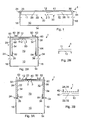
- the Figs 1, 2 and 3 illustrate a microstrip antenna 1 that is short circuited at one end and fed at the other end.
- the antenna 1 comprises: a ground plane 10 having an edge 12; a feed point 2; a ground point 3; and an antenna track 11, of length L, extending between the feed point 2 and the ground point 3 and comprising, in series connection, a first loop 20 and a second loop 30 wherein at least a portion of the first loop 20 and a portion of the second loop 30 are adjacent at least the edge 12 of the ground plane.
- a dielectric substrate can be positioned between the antenna track 11 and the ground plane 10 and typically provides support for the antenna track 11.
- the dielectric substrate can, at least partly, be air.
- the first and second loops 20, 30 may be but are not necessarily the same length L/2.
- the first loop 20 comprises a first antenna track portion 22 extending from the feed point 2 to a first extremity 24, a return bend 26 at the first extremity 24 and a second antenna track portion 28 returning from the first extremity 24 towards the feed point 2.
- the second loop 30 comprises a third antenna track portion 32 extending from the ground point 3 to a second extremity 34, a return bend 36 at the second extremity 34 and a fourth antenna track portion 38 returning from the second extremity 34 towards the ground point 3.
- the second antenna track portion 28 and fourth antenna track portion 38 are interconnected at point 41. There is, in the illustrated examples, a constant separation between the first and second antenna track portions 22, 28 and between the third and fourth antenna track portions 32, 38.
- the separation between the first antenna track portion 22 and the second antenna track portion 28 and the separation between the third antenna track portion 32 and the fourth antenna track portion 38 may be independently varied. This allows the coupling between the antenna track portions to be controlled and thus the ratios of the fundamental and harmonic resonant frequencies to be controlled.
- the antenna has been described as interconnected loops 20, 30 it should be understood that the antenna track 11 may be made from a single, unitary element.
- the first 22, second 28, third 32 and fourth 38 antenna track portions may be co-planar as illustrated in Figs 1 and 2 .
- the first 22 and third 32 antenna track portions may lie in a first lower plane 40 while the second and fourth antenna track portions lie in a second upper plane 42 as illustrated in Fig 3 .
- the first and second antenna track portions 22, 28 extend laterally to a first bend 50 to form a lateral portion 52 of the first loop 20 and then extend longitudinally to the first extremity to form a longitudinal portion 54 of the first loop 20.
- the third 32 and fourth 38 antenna track portions extend laterally to a second bend 60 to form a lateral portion 62 of the second loop 30 and then extend longitudinally to the second extremity 34 to form a longitudinal portion 64 of the second loop 30.
- the bends 50 and 60 are substantially right-angled, however, other angled bends may be used.
- the illustrated antenna 1 consequently has a U shape.
- the length of the longitudinal portions 54, 64 are greater than the length of the lateral portion 52, 62 but less than twice the length of the lateral portions 52,62.
- the lateral portions 52, 62 are approximately 20mm long and the longitudinal portions 54, 64 are approximately 30mm long.
- the ground plane is 110mm long and 40mm wide.
- the longitudinal portions 54, 64 of the first and second loops are physically separated and define a volume 70 between them and over the ground plane 10 that is unused by the antenna 1.
- the lateral portions 52, 62 and the longitudinal portions 54, 64 can but need not completely overlie the ground plane 10.
- the antenna 1 has several resonances. By adjusting the antenna geometry and the relative reactive loading of different antenna track portions, it can be arranged that the antenna has three resonances within the frequency range of interest-the fundamental resonance and its second and third harmonic resonances.
- the second and third harmonic resonances can be tuned close to each other so that they form a dual resonance and thus a continuous, wider operation band than either one of the resonances alone.
- the frequency f 1 is at or about 900 MHz and the frequency f 2 is at or about 1800MHz.
- the third harmonic is tuned, using reactive loading, to bring it towards the second harmonic e.g. so that ⁇ 3 comes close to equaling L.
- the first resonance thereby covers the GSM 850 band and/or GSM900 band and the second and third resonance cover the GSM 1800 band and/or GSM1900 band.
- the reactive loading comprises a first inductive load located at a position where the electric current associated with the third harmonic is greater than the electric current associated with the second harmonic.
- Inductive loading can be achieved, for example, by bending the antenna track or by a local decrease in antenna track width or even by adding an inductor.
- the electric current I 1 for the first resonant mode at a distance x from the ground point is modeled as A.cos( ⁇ x/L)
- the electric current I 2 for the second resonant mode at a distance x from the ground point is modeled as A.cos( 2 ⁇ x/L)
- the electric current I 3 for the third resonant mode at a distance x from the ground point is modeled as A.cos(3 ⁇ x/L)
- inductive loading is provided by bends in the antenna track.
- Inductive loading may be provided by having multiple bends in the antenna track within the regions L/5 ⁇ x ⁇ 2U5 & 3L/5 ⁇ x ⁇ 4L/5.
- the first inductive load is the return bend 36 located at U4 (between U5 and 2L/5) from the ground point 3 and the second inductive load is the return bend 26 located at 3/4L (between 3U5 and 4U5) from the ground point 3.
- the antenna track is without bends where the electrical current associated with the second harmonic is significantly greater then the electric current associated with the third harmonic i.e. in the region between 2L/5 and 3U5 from the ground point and, in particular, around U2 from the ground point 3.
- The.reactive loading may also comprise one or more capacitive loads typically positioned where the electrical field associated with the third harmonic is greater than the electric field associated with the second harmonic.
- Capacitive loading can be achieved by attaching a vertical plate to the edge of an antenna track or by dielectric loading e.g. using a substrate with (effectively) higher dielectric constant between the ground plane and the antenna track.
- capacitive loading can be achieved by attaching a plate to the ground plane or to another grounded component (like an RF shield in a mobile telephone) so that the plate forms a capacitor with a desired section of the antenna track.
- the capacitance is adjusted by varying the separation between the plate and the antenna track as well as the size of the plate. It is also possible to add a capacitor, for example a discrete chip capacitor, between the antenna and its ground plane.
- the electric field E 1 for the first resonant mode at a distance x from the ground point is modeled as B.sin( ⁇ x/L)
- the electric field E 2 for the second resonant mode at a distance x from the ground point is modeled as B.sin( 2 ⁇ x/L)
- the electric field E 3 for the third resonant mode at a distance x from the ground point is modeled as B.sin( 3 ⁇ x/L)
- capacitive loading against the ground plane where the magnitude of E 3 is greater than the magnitude of E 2 , as this will decrease the separation between the second resonant frequency f 2 and the third resonant frequency f 3 .
- Capacitive loads 82, 84 are added where the magnitude of E 2 and E 3 are only slightly different from each other, but greater than the magnitude of E 1 in order to tune the resonant frequencies of the second and third harmonic relative to the fundamental resonance. Suitable regions for capacitive loads are L/5 ⁇ x ⁇ U4 & 3L/4 ⁇ x ⁇ 4U5.
- a capacitive load 80 is located at a position between 2U5 and 3L/5 from the ground point, preferably at U2 from the ground point.
- the second and third harmonic resonances (and hence also the centre frequency of the second band of operation) are tuned relative to the fundamental frequency by adding a capacitive load 82 between U5 and L/4 from the ground point, preferably at L/4, and another capacitive load 84 between 3U4 and 4U5 from the ground point, preferably at 3U4.
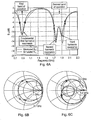
- Fig. 6A illustrates a plot of the reflection coefficient vs frequency for the antenna 1 in free space.
- the plot includes a plot of simulated reflection coefficients and a plot of measured reflection coefficients.
- the Smith Chart for the antenna's first band of operation is illustrated in Fig 6B and the Smith Chart for the antenna's second band of operation is illustrated in Fig. 6C .
- the coupling between the second and third harmonics can be optimized so that a continuous wide second band of operation is produced.
- the bandwidth depends upon the size of the small dual resonance loop in the antenna's Smith chart ( Fig. 6C ). This can be controlled, for example, by adjusting the width of the lateral portions 52, 62 of the first and second loops that are closest to the feed and ground points 2,3.
- the small dual resonance loop of the antenna's impedance locus on the Smith Chart may be centered by increasing/decreasing the relative length of the first loop 20 to the second loop 30. Increasing the relative length moves the small dual resonance loop clockwise along the impedance locus in the Smith chart and decreasing the relative length moves the small dual resonance loop anti-clockwise along the impedance locus in the Smith chart.
- the size of the whole impedance locus and thus also the location of the dual resonance loop can be controlled by adjusting the width of the longitudinal portions 54, 64 of the first and second loops 50, 60 that are closest to the feed and ground points 2, 3. Increasing the width will increase the size of the locus, whereas decreasing the width will decrease it.
- the bandwidth of the first (fundamental) resonance can be optimized by having part of the antenna track 11 overlying the ground plane 10 so that the resonant modes of the antenna couple more strongly to the resonant modes of the ground plane 10. This is not always necessary and, in other embodiments, the antenna track 11 may completely overlie the ground plane 10. In other embodiments the antenna track 11 extends mostly or even totally outside the ground plane 10.
- the ground plane 10 is, in the illustrated examples, rectangular. It has a length K and a width W. It has a first top edge 12, a second bottom edge 14, a third left side edge 16 and a fourth right side edge 18.
- the antenna track 11, in Figs 2 and 3 is adjacent the first top edge 12 and adjacent a portion of the third left side edge 16, where it meets the first top edge 12, and adjacent a portion of the fourth right-side edge 18, where it meets the first top edge 12.
- the ground plane 10 has a well-radiating, low-Q resonances when its effective length is a multiple of ⁇ /2.
- a 110mm long ground plane has resonances at around 1.15 GHz and 2.3 GHz that approximately correspond to wavelengths of 2K and K.
- Increasing the coupling of the high Q small bandwidth resonant modes of the antenna 1 and low-Q large bandwidth resonant modes of ground plane 10 increases the bandwidth of the resonant modes of the antenna 1.
- the coupling can be increased by extending the antenna track 11 beyond the ground plane 10 so that it overhangs the ground plane 10 or by cutting away a portion of the ground plane 10 below the antenna track 11.
- the coupling between the resonant modes of the antenna and the resonant modes of the ground plane is increased.
- the bandwidth can be further increased by extending the antenna edge(s) outside the edge(s) of the ground plane.
- the ground plane has a resonant mode when its effective length is a multiple of ⁇ /2.
- the ground plane has multiple (two) resonant frequencies at the approximate frequency range of interest. Whenever the resonant frequency of the antenna approaches or matches one of the resonant frequencies of the ground plane, considerable radiating currents are excited on the ground plane, and the bandwidth of the structure increases.
- the bandwidths of the resonant modes of the antenna are increased by locating the antenna 1 at the first top edge 12 of the ground plane 10. They are further increased by extending the antenna track 11 partly outside the ground plane 10 along the top edge 12. This improves coupling of the high Q small bandwidth resonant modes of the antenna and low-Q large bandwidth resonant modes of the ground plane.
- Capacitive loads 82, 84 are added where the magnitudes of E 2 and E 3 are only slightly different, but greater than the magnitude of E 1 in order to tune the resonant frequencies of the second and third harmonic relative to the fundamental resonance.
- Suitable regions for capacitive loads are L/5 ⁇ x ⁇ U4 & 3L/4 ⁇ x ⁇ 4L/5.
- the bandwidths of the resonant modes of the antenna 1 are increased by locating the antenna at the edges 12, 16, 18 of the ground plane 10. They are further increased by extending the antenna track 11 outside the ground plane 10 along one or more edges so that it overhangs the ground plane 10. This improves coupling of the high Q small bandwidth resonant modes of the antenna and low-Q large bandwidth resonant modes of the ground plane.
- the longitudinal portions of the first and second loops have a length 30 mm and the lateral portions of the first and second loops have approximate lengths 19mm and 21 mm respectively.
- the antenna 1 is separated from the ground plane by 7 mm and has a volume of only 4 cm 3 .
- the ground plane is 110mm long and 40mm wide.
- the upper edge of the antenna track 11 is extended 1 mm over the edge of the ground plane.
- the left edge of the antenna track is also extended 1 mm over the left edge of the ground plane and/or the right edge of the antenna track is also extended 1 mm over the edge of the ground plane.
- Fig. 7 illustrates one implementation of the U-shaped, co-planar antenna 1 illustrated in Figs 2A and 2B .
- the antenna 1 is formed in two layers stacked one over the other.
- the first antenna track portion 22 and fourth antenna track portion 32 are located in the lower plane 40 and the second antenna track portion 28 and the third antenna track portion 38 are located in the upper plane 42.
- the return bends 26 and 36 extend between the planes 40, 42.
- first antenna track portion 22 and third antenna track portion 32 may be arranged perpendicular to the lower plane 40 instead of co-planar with it.
- any one or more of the first, second, third or fourth track portions may be arranged perpendicular to the ground plane but separated from it.
- the longitudinal portions of the first and second loops have a length 28 mm and the lateral portions of the first and second loops have approximate lengths 23mm and 17mm respectively. It is separated from the ground plane by 7mm and has a volume of only 3 cm 3 .
- the ground plane is 110mm long and 40mm wide.
- the bandwidth and total efficiency of the antenna is increased by locating the antenna at the edges of the ground plane. It is further increased by extending the antenna track outside the ground plane along one or more edges so that it overhangs the ground plane. This improves coupling of the high Q small bandwidth resonant modes of the antenna and low-Q large bandwidth resonant modes of the ground plane.
- the upper edge of the antenna track is extended 1 mm over the edge of the ground plane.
- the left edge of the antenna track may also extend 1 mm over the left edge of the ground plane.
- the right edge of the antenna track may also extend 1 mm over the edge of the ground plane.
- the position of the ground point 2 and feed point 3 can be moved to/from the centre and the ratios of the lengths of the longitudinal portions 54, 56 can be changed to compensate.
- Additional open-ended or short-circuited metal strips or suitable length may be connected or paracitically coupled at appropriate locations of the antenna to provide additional resonances and thus a wider bandwidth (or better impedance match and efficiency).
- the orientation of the antenna on the ground plane can be changed, i.e. the antenna can be rotated e.g. 90, 180, or 270 degrees.
- Fig 4 illustrates a radio transceiver device 100 such as a mobile cellular telephone, cellular base station, or other wireless communication device.
- the radio transceiver device 100 comprises a multi-band internal antenna 1, as described above, radio transceiver circuitry 102 connected to the feed point of the antenna and functional circuitry 104 connected to the radio transceiver circuitry.
- the functional circuitry 104 includes a processor, a memory and input/out put devices such as a microphone, a loudspeaker and a display.
- the electronic components that provide the radio transceiver circuitry 102 and functional circuitry 104 are interconnected via a printed wiring board (PWB).
- the PWB may be used as the ground plane 10 of the antenna 1 and/or may be connected to another conductive object that acts as the ground plane 10.
- the above-described capacitive loads may be electrically controlled.
- a switch and an additional capacitor if necessary can be added in series with the capacitive loads.
- When the switch is off the capacitive loading is less than when the switch is on.
- Thus when the switch is off the resonant frequencies will be higher than when the switch is on.
- This adjustable capacitive load can be added anywhere along the antenna track.
- Metal strips can be connected between portions of the antenna.
- the grounded and fed lateral portions can be connected to each other with a metal strip. This enables adjusting the input impedance level of the antenna.
- the input impedance level affects the level of impedance match at resonance.
- the relative positions of the resonant frequencies of the antenna 1 have been engineered by selective reactive loading.
- inductive loading in series with the antenna track and capacitive loading in parallel with the antenna track were used.
- capacitive loading in parallel with the antenna track could be connected between the antenna track and the ground plane.
- Such an inductive load may be a conductive, possibly meandering, strip.
- a capacitive load could be placed in series with the antenna track by leaving a gap in the track or as a capacitor in series with the track.
- reactive loads may be placed in series and/or parallel with the feed point 2 and/or ground point 3.
- any of the mentioned reactive loads can be made electrically controlled. Such control can be achieved by adding a switch or other control device in series with the load. Turning the switch on and off will vary the loading causing a change in at least one of the resonant frequencies, which in turn will increase the effective bandwidth of the antenna.
- One example of such switched loading can be implemented by connecting the antenna track and the ground with a slightly inductive ground pin that is in series with a switch. The load can be placed anywhere along the antenna track, which extends between the feed and the original ground point. When the switch is on, the length of the antenna track is smaller and the resonant frequencies are higher than when the switch is off. This can extend the effective bandwidth of the antenna to cover e.g. the UMTS frequency range (1920-2170 MHz).
Claims (38)
- Antenne (1) dotée d'une pluralité de fréquences de résonance et comportant :un plan (10) de masse doté d'un premier bord (12) etd'un autre bord ;un point (2) d'alimentation ;un point (3) de masse ; etune piste (11) d'antenne s'étendant entre le point (2) d'alimentation et le point (3) de masse, la piste (11) d'antenne comportant une première boucle (20) et une deuxième boucle (30) raccordées entre le point (2) d'alimentation et le point (3) de masse, la première boucle (20) et la deuxième boucle (30) étant reliées en série ;une partie de la première boucle (20) étant adjacente au premier bord du plan (10) de masse et une partie de la deuxième boucle (30) étant adjacente au premier ou à l'autre bord du plan (10) de masse ;caractérisée en ce quel'antenne possède une première bande continue de fonctionnement et une deuxième bande continue de fonctionnement, la première bande continue de fonctionnement correspondant à une fréquence fondamentale de résonance (première résonance harmonique) de l'antenne et la deuxième bande continue de fonctionnement correspondant à la combinaison des deuxième et troisième résonances harmoniques de la résonance fondamentale de l'antenne, la troisième résonance harmonique étant accordée, en utilisant un chargement réactif, en direction de la deuxième résonance harmonique ; etla piste (11) d'antenne présentant une longueur L, et le chargement réactif comportant une première charge capacitive positionnée entre L/5 et L/4 par rapport au point (3) de masse et une deuxième charge capacitive positionnée entre 3L/4 et 4L/5 par rapport au point (3) de masse.
- Antenne selon la revendication 1, le plan (10) de masse présentant une longueur et un largeur et comportant des premier et deuxième bords (12, 14) s'étendant sur la largeur et séparés par la longueur et des troisième et quatrième autres bords (16, 18) s'étendant sur la longueur et séparés par la largeur, la piste (11) d'antenne s'étendant au voisinage du premier bord (12) et au voisinage d'une partie du troisième bord (16), à l'endroit où il rejoint le premier bord (12), et au voisinage d'une partie de the quatrième bord (18), à l'endroit où il rejoint le premier bord (12).
- Antenne selon la revendication 1 ou 2, une partie, mais non la totalité, de la piste (11) d'antenne se superposant au plan (10) de masse.
- Antenne selon l'une quelconque des revendications précédentes, agencée de telle façon que les modes résonants de l'antenne se couplent fortement aux modes résonants du plan (10) de masse.
- Antenne selon l'une quelconque des revendications précédentes, la première bande continue de fonctionnement couvrant la bande GSM 850 et/ou la bande GSM 900 et la deuxième bande continue de fonctionnement couvrant la bande GSM 1800 et/ou la bande GSM 1900.
- Antenne selon l'une quelconque des revendications précédentes, la piste (11) d'antenne présentant une longueur L et le chargement réactif comportant une première charge inductive située dans une position où le courant électrique associé à la troisième harmonique est supérieur au courant électrique associé à la deuxième harmonique.
- Antenne selon l'une quelconque des revendications précédentes, la piste (11) d'antenne présentant une longueur L et le chargement réactif comportant une première charge inductive située dans une position comprise entre L/5 et 2L/5 par rapport au point (3) de masse et une deuxième charge inductive située dans une position comprise entre 3L/5 et 4L/5 par rapport au point (3) de masse.
- Antenne selon l'une quelconque des revendications précédentes, le chargement réactif comportant une pluralité de coudes dans la piste (11) d'antenne.
- Antenne selon l'une quelconque des revendications précédentes, la piste (11) d'antenne présentant une longueur L et le chargement réactif comportant une ou plusieurs charges capacitives positionnées là où le champ électrique associé à la troisième harmonique est supérieur au champ électrique associé à la deuxième harmonique.
- Antenne selon l'une quelconque des revendications précédentes, la piste (11) d'antenne présentant une longueur L et le chargement réactif comportant au moins une charge capacitive située sensiblement dans une position comprise entre 2L/5 et 3L/5 par rapport au point de masse.
- Antenne selon la revendication 9, une charge capacitive étant située dans une position à L/2 du point (3) de masse.
- Antenne selon l'une quelconque des revendications précédentes, la première charge capacitive étant située à un premier coude de retour de la première boucle (20) et la deuxième charge capacitive étant située à un deuxième coude de retour de la deuxième boucle (30).
- Antenne selon l'une quelconque des revendications précédentes, la piste (11) d'antenne présentant une longueur L et étant dépourvue de coudes où le courant électrique associé à la deuxième harmonique est significativement supérieur au courant électrique associé à la troisième harmonique.
- Antenne selon l'une quelconque des revendications 1 à 12, la piste (11) d'antenne présentant une longueur L et étant dépourvue de coudes à l'intérieur de la région comprise entre 2L/5 et 3L/5 par rapport au point (3) de masse.
- Antenne selon l'une quelconque des revendications précédentes, la piste (11) d'antenne présentant une longueur L et étant dépourvue de coudes aux environs de L/2 par rapport au point (3) de masse.
- Antenne selon l'une quelconque des revendications précédentes, la première boucle (20) comportant une première partie de piste d'antenne s'étendant du point de masse à une première extrémité, un coude de retour au niveau de la première extrémité et un deuxième partie de piste d'antenne revenant de l'extrémité vers le point de masse et la deuxième boucle (20) comportant une troisième partie de piste d'antenne s'étendant du point d'alimentation à une deuxième extrémité, un coude de retour au niveau de la deuxième extrémité et une quatrième partie de piste d'antenne revenant de la deuxième extrémité vers le point d'alimentation, la deuxième partie de piste d'antenne et la quatrième partie de piste d'antenne étant interconnectées.
- Antenne selon la revendication 16, les première et deuxième parties de piste d'antenne présentant une séparation constante et les troisième et quatrième parties de piste d'antenne présentant une séparation constante.
- Antenne selon la revendication 16 ou 17, les première, deuxième, troisième et quatrième parties de piste d'antenne étant coplanaires.
- Antenne selon l'une quelconque des revendications 16 à 17, les première et troisième parties de piste d'antenne se trouvant dans un premier plan et les deuxième et quatrième parties de piste d'antenne se trouvant dans un deuxième plan.
- Antenne selon l'une quelconque des revendications 16 à 19, les première et deuxième parties de piste d'antenne s'étendant latéralement jusqu'à un premier coude pour former une partie latérale de la première boucle (20), puis s'étendant longitudinalement jusqu'à la première extrémité pour former une partie longitudinale de la première boucle (20) et les troisième et quatrième parties de piste d'antenne s'étendant latéralement jusqu'à un deuxième coude pour former une partie latérale de la deuxième boucle (30), puis s'étendant longitudinalement to la deuxième extrémité pour former une partie longitudinale de la deuxième boucle (30).
- Antenne selon la revendication 20, caractérisée en ce que, pour les première et deuxième boucles (20, 30), les longueurs des parties latérales sont inférieures aux longueurs des parties longitudinales.
- Antenne selon la revendication 21, caractérisée en ce que, pour les première et deuxième boucles (20, 30), la longueur d'une partie longitudinale est inférieure au double de la longueur de sa partie latérale.
- Antenne selon l'une quelconque des revendications 20 à 22, les parties longitudinales des première et deuxième boucles (20, 30) étant physiquement séparées et définissant un volume entre elles et au-dessus du plan (10) de masse qui n'est pas utilisé par l'antenne.
- Antenne selon l'une quelconque des revendications 20 à 23, les parties latérales ne se superposant pas entièrement au plan (10) de masse.
- Antenne selon la revendication 24, les parties longitudinales ne se superposant pas entièrement au plan (10) de masse.
- Antenne selon l'une quelconque des revendications 20 à 25, certains segments des parties latérales étant plus larges que tout segment des parties longitudinales correspondantes.
- Antenne selon l'une quelconque des revendications précédentes, chacune des première et deuxième boucles (20, 30) comportant au moins un coude.
- Antenne selon la revendication 27, le coude étant un coude à angle droit.
- Antenne selon la revendication 27 ou 28, la piste d'antenne prenant la forme d'un U.
- Antenne selon l'une quelconque des revendications précédentes, les première et deuxième boucles étant de longueurs différentes.
- Antenne selon la revendication 1, la piste (11) d'antenne présentant une longueur L et la première boucle (20) comprenant un coude de retour entre L/5 et 2L/5 par rapport au point de masse et la deuxième boucle (30) comprenant un coude de retour entre 3L/5 et 4L/5 par rapport au point (3) de masse.
- Antenne selon la revendication 31, présentant une forme en U.
- Dispositif émetteur-récepteur radio (100) comportant une antenne selon l'une quelconque des revendications précédentes.
- Emetteur-récepteur radio selon la revendication 33, l'antenne étant une antenne interne et le bord du plan de masse étant le bord extrême supérieur de la carte à circuit imprimé.
- Emetteur-récepteur radio selon la revendication 33, l'antenne étant une antenne interne et le bord du plan de masse étant le bord extrême inférieur de la carte à circuit imprimé.
- Composant d'émetteur-récepteur radio comportant une antenne selon l'une quelconque des revendications 1 à 32.
- Dispositif émetteur-récepteur radio (100) comportant une antenne selon l'une quelconque des revendications 1 à 32.
- Procédé de formation d'une antenne dotée d'une pluralité de fréquences de résonance, le procédé comportant les étapes consistant à :réaliser un plan (10) de masse doté d'un premier bord (12) et d'un autre bord ;réaliser un point (2) d'alimentation ;réaliser un point (3) de masse ; etréaliser une piste (11) d'antenne s'étendant entre le point (2) d'alimentation et le point (3) de masse, la piste (11) d'antenne comportant une première boucle (20) et une deuxième boucle (30) raccordées entre le point (2) d'alimentation et le point (3) de masse, la première boucle (20) et la deuxième boucle (30) étant reliées en série ;une partie de la première boucle (20) étant adjacente au premier bord du plan (10) de masse et une partie de la deuxième boucle (30) étant adjacente au premier ou à l'autre bord du plan (10) de masse ;caractérisé en ce quel'antenne possède une première bande continue de fonctionnement et une deuxième bande continue de fonctionnement, la première bande continue de fonctionnement correspondant à une fréquence fondamentale de résonance (première résonance harmonique) de l'antenne et la deuxième bande continue de fonctionnement correspondant à la combinaison des deuxième et troisième résonances harmoniques de la résonance fondamentale de l'antenne, la troisième résonance harmonique étant accordée, en utilisant un chargement réactif, en direction de la deuxième résonance harmonique, etla piste (11) d'antenne présentant une longueur L et le chargement réactif comportant au moins une charge capacitive située sensiblement à une position comprise entre 2L/5 et 3L/5 par rapport au point (3) de masse.
Applications Claiming Priority (2)
| Application Number | Priority Date | Filing Date | Title |
|---|---|---|---|
| US11/107,159 US7629931B2 (en) | 2005-04-15 | 2005-04-15 | Antenna having a plurality of resonant frequencies |
| PCT/IB2006/001098 WO2006109184A1 (fr) | 2005-04-15 | 2006-04-12 | Antenne dotee d'une pluralite de frequences de resonance |
Publications (3)
| Publication Number | Publication Date |
|---|---|
| EP1869726A1 EP1869726A1 (fr) | 2007-12-26 |
| EP1869726A4 EP1869726A4 (fr) | 2011-05-04 |
| EP1869726B1 true EP1869726B1 (fr) | 2014-12-31 |
Family
ID=37086641
Family Applications (1)
| Application Number | Title | Priority Date | Filing Date |
|---|---|---|---|
| EP06765419.4A Active EP1869726B1 (fr) | 2005-04-15 | 2006-04-12 | Antenne dotee d'une pluralite de frequences de resonance |
Country Status (4)
| Country | Link |
|---|---|
| US (2) | US7629931B2 (fr) |
| EP (1) | EP1869726B1 (fr) |
| CN (1) | CN101147294B (fr) |
| WO (1) | WO2006109184A1 (fr) |
Families Citing this family (34)
| Publication number | Priority date | Publication date | Assignee | Title |
|---|---|---|---|---|
| US7629931B2 (en) * | 2005-04-15 | 2009-12-08 | Nokia Corporation | Antenna having a plurality of resonant frequencies |
| US7710327B2 (en) * | 2005-11-14 | 2010-05-04 | Mobile Access Networks Ltd. | Multi band indoor antenna |
| JP4311576B2 (ja) | 2005-11-18 | 2009-08-12 | ソニー・エリクソン・モバイルコミュニケーションズ株式会社 | 折り返しダイポールアンテナ装置および携帯無線端末 |
| US7911405B2 (en) * | 2008-08-05 | 2011-03-22 | Motorola, Inc. | Multi-band low profile antenna with low band differential mode |
| CN101652040A (zh) * | 2008-08-15 | 2010-02-17 | 深圳富泰宏精密工业有限公司 | 内置天线的壳体组件及其制造方法 |
| FI20085907L (fi) * | 2008-09-25 | 2010-03-26 | Pulse Finland Oy | Antenniyhdistelmä |
| TW201015788A (en) * | 2008-10-08 | 2010-04-16 | Sunplus Mmobile Inc | Antenna |
| US9172134B2 (en) | 2008-11-06 | 2015-10-27 | Antenna79, Inc. | Protective cover for a wireless device |
| EP2356717A4 (fr) | 2008-11-06 | 2016-06-22 | Antenna79 Inc | Boîtier externe de redirection de rayonnement destiné à un dispositif de communication portatif et antenne intégrée à la batterie d' un dispositif de communication portatif |
| US8214003B2 (en) * | 2009-03-13 | 2012-07-03 | Pong Research Corporation | RF radiation redirection away from portable communication device user |
| TW201027844A (en) * | 2009-01-06 | 2010-07-16 | Ralink Technology Corp | Loop antenna for wireless network |
| WO2010110517A1 (fr) * | 2009-03-23 | 2010-09-30 | Industry-University Cooperation Foundation Hanyang University | Antenne utilisant un élément réactif |
| TWI407634B (zh) * | 2009-08-28 | 2013-09-01 | Arcadyan Technology Corp | 立體雙頻天線 |
| JP4916036B2 (ja) * | 2010-02-23 | 2012-04-11 | カシオ計算機株式会社 | 複数周波アンテナ |
| US20110205126A1 (en) * | 2010-02-25 | 2011-08-25 | Sony Ericsson Mobile Communications Ab | Low-Profile Folded Dipole Antennas and Radio Communications Devices Employing Same |
| EP2403059A1 (fr) * | 2010-06-21 | 2012-01-04 | Research In Motion Limited | Ensemble d'antenne crantée pour dispositif mobile compact |
| TWI515972B (zh) * | 2010-12-28 | 2016-01-01 | 群邁通訊股份有限公司 | 多頻天線 |
| US8648752B2 (en) * | 2011-02-11 | 2014-02-11 | Pulse Finland Oy | Chassis-excited antenna apparatus and methods |
| US9673507B2 (en) | 2011-02-11 | 2017-06-06 | Pulse Finland Oy | Chassis-excited antenna apparatus and methods |
| CN102780071B (zh) * | 2011-05-10 | 2014-12-10 | 鸿富锦精密工业(深圳)有限公司 | 立体天线 |
| US9838060B2 (en) | 2011-11-02 | 2017-12-05 | Antenna79, Inc. | Protective cover for a wireless device |
| CN103094674A (zh) * | 2011-11-08 | 2013-05-08 | 联发科技股份有限公司 | 混合天线、冲压元件、印刷电路板及混合天线制造方法 |
| US9276317B1 (en) * | 2012-03-02 | 2016-03-01 | Amazon Technologies, Inc. | Quad-mode antenna |
| JP2014200031A (ja) * | 2013-03-29 | 2014-10-23 | 富士通株式会社 | アンテナ及び無線通信装置 |
| TWI619304B (zh) * | 2013-05-17 | 2018-03-21 | 群邁通訊股份有限公司 | 寬頻天線及應用該寬頻天線的無線通訊裝置 |
| CN105990650A (zh) * | 2015-02-15 | 2016-10-05 | 泰科电子(上海)有限公司 | 折叠偶极子天线、无线通信模块及其构建方法 |
| US10530042B2 (en) | 2017-09-08 | 2020-01-07 | Apple Inc. | Electronic device having shared antenna structures |
| JP7006495B2 (ja) * | 2018-05-07 | 2022-01-24 | 富士通株式会社 | アンテナ装置 |
| CN109103570B (zh) | 2018-08-03 | 2020-08-21 | 瑞声精密制造科技(常州)有限公司 | 回路天线系统及移动终端 |
| US20200160141A1 (en) * | 2018-11-21 | 2020-05-21 | Konica Minolta Laboratory U.S.A., Inc. | Modified rfid tags |
| US10650203B1 (en) | 2018-11-21 | 2020-05-12 | Konica Minolta Laboratory U.S.A., Inc. | RFID tag, system, and method for tamper detection |
| US10657432B1 (en) | 2018-11-21 | 2020-05-19 | Konica Minolta Laboratory U.S.A., Inc. | System and method for modifying RFID tags |
| US10651565B1 (en) | 2019-04-29 | 2020-05-12 | Microsoft Technology Licensing, Llc | Antenna polarization diversity |
| CN110444893B (zh) * | 2019-08-16 | 2020-05-26 | 歌尔科技有限公司 | 一种单极天线带宽调整方法及系统 |
Family Cites Families (20)
| Publication number | Priority date | Publication date | Assignee | Title |
|---|---|---|---|---|
| US5315309A (en) * | 1991-09-06 | 1994-05-24 | Mcdonnell Douglas Helicopter Company | Dual polarization antenna |
| DK168780B1 (da) * | 1992-04-15 | 1994-06-06 | Celwave R F A S | Antennesystem samt fremgangsmåde til fremstilling heraf |
| US5557293A (en) * | 1995-01-26 | 1996-09-17 | Motorola, Inc. | Multi-loop antenna |
| US5654724A (en) * | 1995-08-07 | 1997-08-05 | Datron/Transco Inc. | Antenna providing hemispherical omnidirectional coverage |
| US5764195A (en) * | 1996-07-24 | 1998-06-09 | Hazeltine Corporation | UHF/VHF multifunction ocean antenna system |
| US5880697A (en) * | 1996-09-25 | 1999-03-09 | Torrey Science Corporation | Low-profile multi-band antenna |
| WO1999013528A1 (fr) * | 1997-09-10 | 1999-03-18 | Rangestar International Corporation | Ensemble d'antenne a cadre pour dispositifs de telecommunications |
| US6014107A (en) * | 1997-11-25 | 2000-01-11 | The United States Of America As Represented By The Secretary Of The Navy | Dual orthogonal near vertical incidence skywave antenna |
| US6252561B1 (en) * | 1999-08-02 | 2001-06-26 | Accton Technology Corporation | Wireless LAN antenna with single loop |
| AU778969B2 (en) * | 1999-11-03 | 2004-12-23 | Andrew Corporation | Folded dipole antenna |
| FI113812B (fi) * | 2000-10-27 | 2004-06-15 | Nokia Corp | Radiolaite ja antennirakenne |
| US20030098814A1 (en) * | 2001-11-09 | 2003-05-29 | Keller Walter John | Multiband antenna formed of superimposed compressed loops |
| US6597318B1 (en) * | 2002-06-27 | 2003-07-22 | Harris Corporation | Loop antenna and feed coupler for reduced interaction with tuning adjustments |
| US6917335B2 (en) * | 2002-11-08 | 2005-07-12 | Centurion Wireless Technologies, Inc. | Antenna with shorted active and passive planar loops and method of making the same |
| US6909402B2 (en) * | 2003-06-11 | 2005-06-21 | Sony Ericsson Mobile Communications Ab | Looped multi-branch planar antennas having multiple resonant frequency bands and wireless terminals incorporating the same |
| JP3790249B2 (ja) * | 2004-01-13 | 2006-06-28 | 株式会社東芝 | ループアンテナ及びループアンテナを備えた無線通信機 |
| GB2415832B (en) * | 2004-06-30 | 2008-03-26 | Nokia Corp | An antenna |
| US7307591B2 (en) * | 2004-07-20 | 2007-12-11 | Nokia Corporation | Multi-band antenna |
| US7629931B2 (en) * | 2005-04-15 | 2009-12-08 | Nokia Corporation | Antenna having a plurality of resonant frequencies |
| TWI270235B (en) * | 2005-07-08 | 2007-01-01 | Ind Tech Res Inst | High-gain loop antenna |
-
2005
- 2005-04-15 US US11/107,159 patent/US7629931B2/en active Active
-
2006
- 2006-04-12 EP EP06765419.4A patent/EP1869726B1/fr active Active
- 2006-04-12 WO PCT/IB2006/001098 patent/WO2006109184A1/fr not_active Application Discontinuation
- 2006-04-12 CN CN200680009653XA patent/CN101147294B/zh active Active
-
2008
- 2008-05-05 US US12/151,293 patent/US7705791B2/en active Active
Also Published As
| Publication number | Publication date |
|---|---|
| CN101147294A (zh) | 2008-03-19 |
| US20060232477A1 (en) | 2006-10-19 |
| WO2006109184A1 (fr) | 2006-10-19 |
| EP1869726A1 (fr) | 2007-12-26 |
| US20080211725A1 (en) | 2008-09-04 |
| CN101147294B (zh) | 2012-04-04 |
| US7705791B2 (en) | 2010-04-27 |
| EP1869726A4 (fr) | 2011-05-04 |
| US7629931B2 (en) | 2009-12-08 |
Similar Documents
| Publication | Publication Date | Title |
|---|---|---|
| EP1869726B1 (fr) | Antenne dotee d'une pluralite de frequences de resonance | |
| US7889143B2 (en) | Multiband antenna system and methods | |
| KR100993439B1 (ko) | 안테나 장치 및 무선 통신 장치 | |
| US7205942B2 (en) | Multi-band antenna arrangement | |
| US7256743B2 (en) | Internal multiband antenna | |
| EP2628209B1 (fr) | Une antenne cadre pour téléphones portables et autres applications | |
| US8629813B2 (en) | Adjustable multi-band antenna and methods | |
| US7403160B2 (en) | Low profile smart antenna for wireless applications and associated methods | |
| US6980154B2 (en) | Planar inverted F antennas including current nulls between feed and ground couplings and related communications devices | |
| US7307591B2 (en) | Multi-band antenna | |
| EP2250702B1 (fr) | Antenne multibande ajustable | |
| US7482991B2 (en) | Multi-band compact PIFA antenna with meandered slot(s) | |
| EP2445053B1 (fr) | Dispositif de communication mobile et antenne | |
| JP5009240B2 (ja) | マルチバンドアンテナ及び無線通信端末 | |
| EP1656713A1 (fr) | Systeme antennaire, module et appareil de radiocommunications integrant un tel systeme | |
| JP2002185238A (ja) | デュアルバンド対応内蔵アンテナ装置およびこれを備えた携帯無線端末 | |
| EP2662925B1 (fr) | Dispositif de communication et structure d'antenne correspondante | |
| JPH09232854A (ja) | 移動無線機用小型平面アンテナ装置 | |
| US8325095B2 (en) | Antenna element and portable radio | |
| US7522936B2 (en) | Wireless terminal | |
| WO2001020716A1 (fr) | Systeme d'antenne et procede servant a reduire la taille du fouet dudit systeme d'antenne |
Legal Events
| Date | Code | Title | Description |
|---|---|---|---|
| PUAI | Public reference made under article 153(3) epc to a published international application that has entered the european phase |
Free format text: ORIGINAL CODE: 0009012 |
|
| 17P | Request for examination filed |
Effective date: 20070813 |
|
| AK | Designated contracting states |
Kind code of ref document: A1 Designated state(s): AT BE BG CH CY CZ DE DK EE ES FI FR GB GR HU IE IS IT LI LT LU LV MC NL PL PT RO SE SI SK TR |
|
| DAX | Request for extension of the european patent (deleted) | ||
| A4 | Supplementary search report drawn up and despatched |
Effective date: 20110404 |
|
| 17Q | First examination report despatched |
Effective date: 20131031 |
|
| RIC1 | Information provided on ipc code assigned before grant |
Ipc: H01Q 9/26 20060101ALI20131206BHEP Ipc: H01Q 1/38 20060101ALI20131206BHEP Ipc: H01Q 1/24 20060101AFI20131206BHEP |
|
| RAP1 | Party data changed (applicant data changed or rights of an application transferred) |
Owner name: NOKIA CORPORATION |
|
| GRAP | Despatch of communication of intention to grant a patent |
Free format text: ORIGINAL CODE: EPIDOSNIGR1 |
|
| INTG | Intention to grant announced |
Effective date: 20140812 |
|
| GRAS | Grant fee paid |
Free format text: ORIGINAL CODE: EPIDOSNIGR3 |
|
| GRAA | (expected) grant |
Free format text: ORIGINAL CODE: 0009210 |
|
| AK | Designated contracting states |
Kind code of ref document: B1 Designated state(s): AT BE BG CH CY CZ DE DK EE ES FI FR GB GR HU IE IS IT LI LT LU LV MC NL PL PT RO SE SI SK TR |
|
| REG | Reference to a national code |
Ref country code: CH Ref legal event code: EP Ref country code: GB Ref legal event code: FG4D |
|
| REG | Reference to a national code |
Ref country code: DE Ref legal event code: R081 Ref document number: 602006044191 Country of ref document: DE Owner name: NOKIA TECHNOLOGIES OY, FI Free format text: FORMER OWNER: NOKIA CORP., 02610 ESPOO, FI |
|
| REG | Reference to a national code |
Ref country code: IE Ref legal event code: FG4D |
|
| REG | Reference to a national code |
Ref country code: AT Ref legal event code: REF Ref document number: 704866 Country of ref document: AT Kind code of ref document: T Effective date: 20150215 |
|
| REG | Reference to a national code |
Ref country code: DE Ref legal event code: R096 Ref document number: 602006044191 Country of ref document: DE Effective date: 20150219 |
|
| REG | Reference to a national code |
Ref country code: NL Ref legal event code: T3 |
|
| PG25 | Lapsed in a contracting state [announced via postgrant information from national office to epo] |
Ref country code: LT Free format text: LAPSE BECAUSE OF FAILURE TO SUBMIT A TRANSLATION OF THE DESCRIPTION OR TO PAY THE FEE WITHIN THE PRESCRIBED TIME-LIMIT Effective date: 20141231 Ref country code: FI Free format text: LAPSE BECAUSE OF FAILURE TO SUBMIT A TRANSLATION OF THE DESCRIPTION OR TO PAY THE FEE WITHIN THE PRESCRIBED TIME-LIMIT Effective date: 20141231 |
|
| REG | Reference to a national code |
Ref country code: LT Ref legal event code: MG4D |
|
| PG25 | Lapsed in a contracting state [announced via postgrant information from national office to epo] |
Ref country code: GR Free format text: LAPSE BECAUSE OF FAILURE TO SUBMIT A TRANSLATION OF THE DESCRIPTION OR TO PAY THE FEE WITHIN THE PRESCRIBED TIME-LIMIT Effective date: 20150401 Ref country code: LV Free format text: LAPSE BECAUSE OF FAILURE TO SUBMIT A TRANSLATION OF THE DESCRIPTION OR TO PAY THE FEE WITHIN THE PRESCRIBED TIME-LIMIT Effective date: 20141231 Ref country code: SE Free format text: LAPSE BECAUSE OF FAILURE TO SUBMIT A TRANSLATION OF THE DESCRIPTION OR TO PAY THE FEE WITHIN THE PRESCRIBED TIME-LIMIT Effective date: 20141231 |
|
| REG | Reference to a national code |
Ref country code: AT Ref legal event code: MK05 Ref document number: 704866 Country of ref document: AT Kind code of ref document: T Effective date: 20141231 |
|
| PG25 | Lapsed in a contracting state [announced via postgrant information from national office to epo] |
Ref country code: ES Free format text: LAPSE BECAUSE OF FAILURE TO SUBMIT A TRANSLATION OF THE DESCRIPTION OR TO PAY THE FEE WITHIN THE PRESCRIBED TIME-LIMIT Effective date: 20141231 Ref country code: CZ Free format text: LAPSE BECAUSE OF FAILURE TO SUBMIT A TRANSLATION OF THE DESCRIPTION OR TO PAY THE FEE WITHIN THE PRESCRIBED TIME-LIMIT Effective date: 20141231 Ref country code: RO Free format text: LAPSE BECAUSE OF FAILURE TO SUBMIT A TRANSLATION OF THE DESCRIPTION OR TO PAY THE FEE WITHIN THE PRESCRIBED TIME-LIMIT Effective date: 20141231 Ref country code: SK Free format text: LAPSE BECAUSE OF FAILURE TO SUBMIT A TRANSLATION OF THE DESCRIPTION OR TO PAY THE FEE WITHIN THE PRESCRIBED TIME-LIMIT Effective date: 20141231 |
|
| PG25 | Lapsed in a contracting state [announced via postgrant information from national office to epo] |
Ref country code: IS Free format text: LAPSE BECAUSE OF FAILURE TO SUBMIT A TRANSLATION OF THE DESCRIPTION OR TO PAY THE FEE WITHIN THE PRESCRIBED TIME-LIMIT Effective date: 20150430 Ref country code: PL Free format text: LAPSE BECAUSE OF FAILURE TO SUBMIT A TRANSLATION OF THE DESCRIPTION OR TO PAY THE FEE WITHIN THE PRESCRIBED TIME-LIMIT Effective date: 20141231 Ref country code: AT Free format text: LAPSE BECAUSE OF FAILURE TO SUBMIT A TRANSLATION OF THE DESCRIPTION OR TO PAY THE FEE WITHIN THE PRESCRIBED TIME-LIMIT Effective date: 20141231 |
|
| REG | Reference to a national code |
Ref country code: DE Ref legal event code: R097 Ref document number: 602006044191 Country of ref document: DE |
|
| REG | Reference to a national code |
Ref country code: GB Ref legal event code: 732E Free format text: REGISTERED BETWEEN 20150910 AND 20150916 |
|
| REG | Reference to a national code |
Ref country code: DE Ref legal event code: R081 Ref document number: 602006044191 Country of ref document: DE Owner name: NOKIA TECHNOLOGIES OY, FI Free format text: FORMER OWNER: NOKIA CORP., ESPOO, FI |
|
| PG25 | Lapsed in a contracting state [announced via postgrant information from national office to epo] |
Ref country code: DK Free format text: LAPSE BECAUSE OF FAILURE TO SUBMIT A TRANSLATION OF THE DESCRIPTION OR TO PAY THE FEE WITHIN THE PRESCRIBED TIME-LIMIT Effective date: 20141231 Ref country code: EE Free format text: LAPSE BECAUSE OF FAILURE TO SUBMIT A TRANSLATION OF THE DESCRIPTION OR TO PAY THE FEE WITHIN THE PRESCRIBED TIME-LIMIT Effective date: 20141231 |
|
| PLBE | No opposition filed within time limit |
Free format text: ORIGINAL CODE: 0009261 |
|
| STAA | Information on the status of an ep patent application or granted ep patent |
Free format text: STATUS: NO OPPOSITION FILED WITHIN TIME LIMIT |
|
| PG25 | Lapsed in a contracting state [announced via postgrant information from national office to epo] |
Ref country code: LU Free format text: LAPSE BECAUSE OF FAILURE TO SUBMIT A TRANSLATION OF THE DESCRIPTION OR TO PAY THE FEE WITHIN THE PRESCRIBED TIME-LIMIT Effective date: 20150412 Ref country code: MC Free format text: LAPSE BECAUSE OF FAILURE TO SUBMIT A TRANSLATION OF THE DESCRIPTION OR TO PAY THE FEE WITHIN THE PRESCRIBED TIME-LIMIT Effective date: 20141231 |
|
| REG | Reference to a national code |
Ref country code: CH Ref legal event code: PL |
|
| 26N | No opposition filed |
Effective date: 20151001 |
|
| PG25 | Lapsed in a contracting state [announced via postgrant information from national office to epo] |
Ref country code: IT Free format text: LAPSE BECAUSE OF FAILURE TO SUBMIT A TRANSLATION OF THE DESCRIPTION OR TO PAY THE FEE WITHIN THE PRESCRIBED TIME-LIMIT Effective date: 20141231 |
|
| REG | Reference to a national code |
Ref country code: IE Ref legal event code: MM4A |
|
| PG25 | Lapsed in a contracting state [announced via postgrant information from national office to epo] |
Ref country code: LI Free format text: LAPSE BECAUSE OF NON-PAYMENT OF DUE FEES Effective date: 20150430 Ref country code: CH Free format text: LAPSE BECAUSE OF NON-PAYMENT OF DUE FEES Effective date: 20150430 |
|
| REG | Reference to a national code |
Ref country code: FR Ref legal event code: ST Effective date: 20151231 |
|
| PG25 | Lapsed in a contracting state [announced via postgrant information from national office to epo] |
Ref country code: SI Free format text: LAPSE BECAUSE OF FAILURE TO SUBMIT A TRANSLATION OF THE DESCRIPTION OR TO PAY THE FEE WITHIN THE PRESCRIBED TIME-LIMIT Effective date: 20141231 Ref country code: FR Free format text: LAPSE BECAUSE OF NON-PAYMENT OF DUE FEES Effective date: 20150430 |
|
| REG | Reference to a national code |
Ref country code: NL Ref legal event code: PD Owner name: NOKIA TECHNOLOGIES OY; FI Free format text: DETAILS ASSIGNMENT: VERANDERING VAN EIGENAAR(S), OVERDRACHT; FORMER OWNER NAME: NOKIA CORPORATION Effective date: 20151111 |
|
| PG25 | Lapsed in a contracting state [announced via postgrant information from national office to epo] |
Ref country code: IE Free format text: LAPSE BECAUSE OF NON-PAYMENT OF DUE FEES Effective date: 20150412 |
|
| PG25 | Lapsed in a contracting state [announced via postgrant information from national office to epo] |
Ref country code: BE Free format text: LAPSE BECAUSE OF FAILURE TO SUBMIT A TRANSLATION OF THE DESCRIPTION OR TO PAY THE FEE WITHIN THE PRESCRIBED TIME-LIMIT Effective date: 20141231 |
|
| PG25 | Lapsed in a contracting state [announced via postgrant information from national office to epo] |
Ref country code: BG Free format text: LAPSE BECAUSE OF FAILURE TO SUBMIT A TRANSLATION OF THE DESCRIPTION OR TO PAY THE FEE WITHIN THE PRESCRIBED TIME-LIMIT Effective date: 20141231 Ref country code: HU Free format text: LAPSE BECAUSE OF FAILURE TO SUBMIT A TRANSLATION OF THE DESCRIPTION OR TO PAY THE FEE WITHIN THE PRESCRIBED TIME-LIMIT; INVALID AB INITIO Effective date: 20060412 |
|
| PG25 | Lapsed in a contracting state [announced via postgrant information from national office to epo] |
Ref country code: CY Free format text: LAPSE BECAUSE OF FAILURE TO SUBMIT A TRANSLATION OF THE DESCRIPTION OR TO PAY THE FEE WITHIN THE PRESCRIBED TIME-LIMIT Effective date: 20141231 |
|
| PG25 | Lapsed in a contracting state [announced via postgrant information from national office to epo] |
Ref country code: PT Free format text: LAPSE BECAUSE OF FAILURE TO SUBMIT A TRANSLATION OF THE DESCRIPTION OR TO PAY THE FEE WITHIN THE PRESCRIBED TIME-LIMIT Effective date: 20150501 |
|
| PG25 | Lapsed in a contracting state [announced via postgrant information from national office to epo] |
Ref country code: TR Free format text: LAPSE BECAUSE OF FAILURE TO SUBMIT A TRANSLATION OF THE DESCRIPTION OR TO PAY THE FEE WITHIN THE PRESCRIBED TIME-LIMIT Effective date: 20141231 |
|
| PGFP | Annual fee paid to national office [announced via postgrant information from national office to epo] |
Ref country code: GB Payment date: 20230302 Year of fee payment: 18 |
|
| PGFP | Annual fee paid to national office [announced via postgrant information from national office to epo] |
Ref country code: NL Payment date: 20230314 Year of fee payment: 18 |
|
| P01 | Opt-out of the competence of the unified patent court (upc) registered |
Effective date: 20230527 |
|
| PGFP | Annual fee paid to national office [announced via postgrant information from national office to epo] |
Ref country code: DE Payment date: 20230307 Year of fee payment: 18 |