EP1869359B1 - Einleitungsschmiereinrichtung - Google Patents
Einleitungsschmiereinrichtung Download PDFInfo
- Publication number
- EP1869359B1 EP1869359B1 EP06723367A EP06723367A EP1869359B1 EP 1869359 B1 EP1869359 B1 EP 1869359B1 EP 06723367 A EP06723367 A EP 06723367A EP 06723367 A EP06723367 A EP 06723367A EP 1869359 B1 EP1869359 B1 EP 1869359B1
- Authority
- EP
- European Patent Office
- Prior art keywords
- line
- lubricant
- pump
- lubrication device
- pressure relief
- Prior art date
- Legal status (The legal status is an assumption and is not a legal conclusion. Google has not performed a legal analysis and makes no representation as to the accuracy of the status listed.)
- Expired - Lifetime
Links
Images
Classifications
-
- F—MECHANICAL ENGINEERING; LIGHTING; HEATING; WEAPONS; BLASTING
- F16—ENGINEERING ELEMENTS AND UNITS; GENERAL MEASURES FOR PRODUCING AND MAINTAINING EFFECTIVE FUNCTIONING OF MACHINES OR INSTALLATIONS; THERMAL INSULATION IN GENERAL
- F16N—LUBRICATING
- F16N7/00—Arrangements for supplying oil or unspecified lubricant from a stationary reservoir or the equivalent in or on the machine or member to be lubricated
- F16N7/38—Arrangements for supplying oil or unspecified lubricant from a stationary reservoir or the equivalent in or on the machine or member to be lubricated with a separate pump; Central lubrication systems
-
- F—MECHANICAL ENGINEERING; LIGHTING; HEATING; WEAPONS; BLASTING
- F16—ENGINEERING ELEMENTS AND UNITS; GENERAL MEASURES FOR PRODUCING AND MAINTAINING EFFECTIVE FUNCTIONING OF MACHINES OR INSTALLATIONS; THERMAL INSULATION IN GENERAL
- F16N—LUBRICATING
- F16N13/00—Lubricating-pumps
- F16N13/02—Lubricating-pumps with reciprocating piston
- F16N13/06—Actuation of lubricating-pumps
- F16N13/10—Actuation of lubricating-pumps with mechanical drive
- F16N13/14—Actuation of lubricating-pumps with mechanical drive with cam or wobble-plate on shaft parallel to the pump cylinder or cylinders
-
- F—MECHANICAL ENGINEERING; LIGHTING; HEATING; WEAPONS; BLASTING
- F16—ENGINEERING ELEMENTS AND UNITS; GENERAL MEASURES FOR PRODUCING AND MAINTAINING EFFECTIVE FUNCTIONING OF MACHINES OR INSTALLATIONS; THERMAL INSULATION IN GENERAL
- F16N—LUBRICATING
- F16N13/00—Lubricating-pumps
- F16N13/22—Lubricating-pumps with distributing equipment
-
- F—MECHANICAL ENGINEERING; LIGHTING; HEATING; WEAPONS; BLASTING
- F16—ENGINEERING ELEMENTS AND UNITS; GENERAL MEASURES FOR PRODUCING AND MAINTAINING EFFECTIVE FUNCTIONING OF MACHINES OR INSTALLATIONS; THERMAL INSULATION IN GENERAL
- F16N—LUBRICATING
- F16N7/00—Arrangements for supplying oil or unspecified lubricant from a stationary reservoir or the equivalent in or on the machine or member to be lubricated
- F16N7/38—Arrangements for supplying oil or unspecified lubricant from a stationary reservoir or the equivalent in or on the machine or member to be lubricated with a separate pump; Central lubrication systems
- F16N7/385—Central lubrication systems
Definitions
- the invention relates to an inlet lubrication device with a lubricant reservoir and a lubricant pump drivable by a drive motor with at least one pump element for conveying lubricant via a lubricant line to at least one lubrication point, in particular at least one inlet manifold, and with a drive member such as a drive shaft, and possibly with an eccentric having means for generating at least one pump stroke of the at least one pump element.
- an inlet lubrication device with a ball valve operable by a drive shaft by means of an actuating pin arranged on an eccentric for opening or closing a lubricant return line.
- a locking element in a first, the ball of the ball valve with a spring force loading position and a second, the ball relieving position are locked.
- the object of the invention is to provide a relief device with a lower design effort, which corresponds to the aforementioned requirement as reliable as possible.
- the solution according to the invention consists e.g.
- a pressure relief device which is also actuated via the drive member for the at least one pump element and in a pressure phase, a return line between the lubricant line and the lubricant reservoir locks and releases in a subsequent discharge phase
- said the pressure relief unit comprises a rocker mechanism operable by the actuator.
- the pressure relief unit can be actuated by a cam member which is seated on the drive element, such as the drive shaft, or the like actuating element.
- the pressure relief unit rests on a cam surface of the actuating element via a wheel or similar transmission element.
- the opening and closing of the connection between the lubricant line and the lubricant reservoir for the return of lubricant may be e.g. be solved in a structurally simple manner, that the pressure relief unit comprises an axially displaceable control piston, which blocks the return line between the lubricant line and the lubricant supply in the pressure phase and in the subsequent discharge phase, e.g. due to a circumferential on the peripheral surface of the control piston groove releases.
- the pressure relief phase can be introduced in the proposed single-line lubrication device in a simple manner by reversing the direction of movement of the drive member with the actuator.
- a compact design of the inlet lubrication device is obtained in particular when the at least one pump element and the pressure relief unit are accommodated in a common pump housing.
- the drive motor possibly with the associated gear z. B. attached to the bottom of the pump housing.
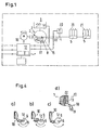
- FIG. 1 the single-line lubrication device according to the invention on a lubricant pump 2, the pump elements 3 of an electric Drive motor 16 are actuated to promote lubricant from a lubricant reservoir 1 in a lubricant line 4.
- the lubricant line 4 leads (in the illustrated case) two single-line distributors 5, from which corresponding supply lines 21 branch off to the individual lubrication points.
- a pressure switch 20 is provided, which shuts off the further lubricant delivery by delivering a corresponding signal by means of a controller 17 to the drive motor 16 upon reaching a maximum pump pressure provided.
- the controller 17 also monitors the lubricant level in the lubricant reservoir 1.
- FIG. 1 is also indicated that in addition to the one or more pump elements 3, a pressure relief unit is provided in the pump housing 15.
- the pressure relief unit 8 is turned on in a return line 22, which connects the lubricant line 4 between the pump element 3 and pressure switch 20 with the lubricant reservoir 1.
- the pressure relief unit 8 closes in the pressure phase, in which the lubrication points are to be supplied with lubricant, the return line 22, however, opens it in a subsequent discharge phase.
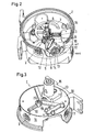
- FIG. 2 illustrates an exemplary structure of a lubricant pump 2 according to the invention with such a pressure relief unit 8.
- the three pump elements 3 are driven by the motor 16 via a drive element 6 designed as a drive shaft and a wheel-like eccentric 7 (FIG. which is shown partially broken away) are actuated at intervals to promote lubricant in the lubricant line 4.
- a pump element 3 has, for example, a delivery piston, which can perform a stroke against the action of a restoring spring by acting on the eccentric 7 in order to dispense a certain amount of lubricant from a lubricant chamber in the direction of the lubricant line 4.
- an actuating element 9 embodied as a cam disk sits on the drive member 6 and acts with its cam surface 12 on a rocker mechanism 10 via a transmission element 11 configured as a wheel.
- the rocker mechanism 10 in turn cooperates with a control piston 13, which blocks the return line 22 between the at least one lubrication point, in particular the pressure switch 20, and the lubricant reservoir 1 in the pressure phase.
- a subsequent to the pressure phase discharge phase by reversing the direction of rotation of the cam 9, as in detail FIG.
- the control piston 13 which has a circumferential groove 14 on its circumference, pushed into a position in which the return line 22 between the at least one lubrication point and the lubricant reservoir 1 is released, so that pressurized, unused lubricant back into the Lubricant supply 1 is performed.
- the rocker arm assembly is in adaptation to the cam surface 12 of the cam disc 9, as shown FIG. 4 can be seen, made such that in the printing phase, ie upon rotation of the cam disc 9, in the forward direction no force is transmitted to the rocker mechanism 10. This is only the case when the cam 9 is rotated in the relief phase in the reverse direction of the drive member 6.
- FIG. 3 It can be seen that the drive motor 16 and the gear 23 can be attached to the bottom 18 of the pump housing 15 to create a structural unit.
- FIG. 3 It can also be seen that at the bottom 18 of the pump housing 15 and the pressure switch 20 is provided and the individual pump elements 3 are provided on the bottom 18 provided on the lubricant channels 19 with each other.
Landscapes
- Engineering & Computer Science (AREA)
- General Engineering & Computer Science (AREA)
- Mechanical Engineering (AREA)
- General Details Of Gearings (AREA)
- Details And Applications Of Rotary Liquid Pumps (AREA)
- Details Of Reciprocating Pumps (AREA)
- Auxiliary Devices For Machine Tools (AREA)
- Processing Of Meat And Fish (AREA)
- Flexible Shafts (AREA)
- Electrical Discharge Machining, Electrochemical Machining, And Combined Machining (AREA)
- Reciprocating Pumps (AREA)
- Lubrication Of Internal Combustion Engines (AREA)
Description
- Die Erfindung bezieht sich auf eine Einleitungsschmiereinrichtung mit einem Schmierstoffvorrat und einer von einem Antriebsmotor antreibbaren Schmierstoffpumpe mit wenigstens einem Pumpenelement zur Förderung von Schmierstoff über eine Schmierstoffleitung zu wenigstens einer Schmierstelle, insbesondere wenigstens einem Einleitungsverteiler, sowie mit einem Antriebsorgan, wie einer Antriebswelle, und ggf. mit einen Exzenter aufweisenden Mitteln zu Erzeugung wenigstens eines Pumpenhubes des wenigstens einen Pumpenelements.
- Bei derartigen Einleitungsschmiereinrichtungen stellt sich die Aufgabe, auf möglichst einfache Weise nach einer Druckphase, in welcher Schmierstoff der wenigstens einen Schmierstelle zugeführt wird, eine Entlastungsphase einzuleiten, in welcher überschüssiger Schmierstoff dem Schmierstoffvorrat zurückgeführt wird.
- Aus der Offenlegungsschrift
EP 0 473 385 A1 ist eine Einleitungsschmiereinrichtung mit einem von einer Antriebswelle mittels eines an einem Exzenter angeordneten Betätigungsstifts betätigbaren Kugelventil zum Öffnen bzw. Verschließen einer Schmierstoff-Rückflussleitung bekannt. Dabei kann ein Verriegelungselement in einer ersten, die Kugel des Kugelventils mit einer Federkraft belastenden Stellung und einer zweiten, die Kugel entlastenden Stellung verriegelt werden. - Aufgabe der Erfindung ist es, eine Entlastungseinrichtung mit einem geringeren konstruktiven Aufwand anzugeben, welche der eingangs genannten Forderung auf möglichst zuverlässige Weise entspricht.
- Die erfindungsgemäße Lösung besteht z.B. im Wesentlichen darin, dass bei einer Einleitungsschmiereinrichtung der eingangs genannten Art eine Druckentlastungseinrichtung vorgesehen ist, welche ebenfalls über das Antriebsorgan für das wenigstens eine Pumpenelement betätigbar ist und in einer Druckphase eine Rückflussleitung zwischen der Schmierstoffleitung und dem Schmierstoffvorrat sperrt sowie in einer anschließenden Entlastungsphase freigibt, wobei die Druckentlastungseinheit einen von dem Betätigungselement betätigbaren Kipphebelmechanismus aufweist.
- Auf diese Weise wird die Druckentlastung nach der Versorgung der wenigstens einen Schmierstelle mit Schmierstoff auf einfache Weise unter weitgehender Nutzung der bereits vorhandenen Einrichtungsteile erreicht.
- In Weiterbildung des Erfindungsgedankens kann die Druckentlastungseinheit von einem auf dem Antriebsorgan, wie der Antriebswelle, sitzenden Nockenscheibe oder dergleichen Betätigungselement betätigbar sein.
- Bevorzugt liegt dabei die Druckentlastungseinheit über ein Rad oder dergleichen Übertragungselement an einer Nockenfläche des Betätigungselements an.
- Das Öffnen und Schließen der Verbindung zwischen Schmierstoffleitung und Schmierstoffvorrat zur Rückführung von Schmierstoff kann z.B. dadurch auf konstruktiv einfache Weise gelöst werden, dass die Druckentlastungseinheit einen axial verschiebbaren Steuerkolben aufweist, welcher in der Druckphase die Rückflussleitung zwischen der Schmierstoffleitung und dem Schmierstoffvorrat sperrt und in der anschließenden Entlastungsphase, z.B. aufgrund einer auf der Umfangsfläche des Steuerkolbens umlaufenden Nut, freigibt.
- Die Druckentlastungsphase kann bei der vorgeschlagenen Einleitungsschmiereinrichtung auf einfache Weise durch Umkehren der Bewegungsrichtung des Antriebsorgans mit dem Betätigungselement eingeleitet werden.
- Eine kompakte Bauart der Einleitungsschmiereinrichtung erhält man insbesondere dann, wenn das wenigstens eine Pumpenelement und die Druckentlastungseinheit in einem gemeinsamen Pumpgehäuse untergebracht sind.
- Dabei kann der Antriebsmotor, ggf. mit dem zugehörigen Getriebe z. B. am Boden des Pumpengehäuses befestigt sein.
- Wenn mehrere Pumpenelemente vorgesehen sind, wird mit der Erfindung unabhängig von der Druckentlastungseinheit ferner vorgeschlagen, dass diese miteinander, ggf. über, an oder in dem Boden des Pumpengehäuses vorgesehene Schmierstoffkanäle, in Strömungsverbindung stehen.
- Weitere Ziele, Merkmale, Vorteile und Anwendungsmöglichkeiten der Erfindung ergeben sich aus der nachfolgenden Beschreibung von Ausführungsbeispielen anhand der Zeichnungen. Dabei bilden alle beschriebenen und/oder bildlich dargestellten Merkmale für sich oder in beliebiger Kombination den Gegenstand der Erfindung, auch unabhängig von ihrer Zusammenfassung in einzelnen Ansprüchen oder deren Rückbeziehung.
- Es zeigen:
- Figur 1
- ein Prinzipschema einer die Erfindung aufweisenden Einleitungs- schmiereinrichtung,
- Figur 2
- schematisch in Schrägansicht von oben, geöffnet und teilweise weggebrochen, eine Schmierstoffpumpe, welche bei der Verwirkli- chung der Erfindung Einsatz finden kann,
- Figur 3
- die Schmierstoffpumpe gemäß
Figur 2 , von unten gesehen und - Figur 4
- schematisch ein Ausführungsbeispiel einer bei der Schmierstoff- pumpe gemäß
Figur 2 und 3 mit Kipphebelmechanismus ausgebil- deten Druckentlastungseinheit. - Gemäß
Figur 1 weist die erfindungsgemäße Einleitungsschmiereinrichtung eine Schmierstoffpumpe 2 auf, deren Pumpenelemente 3 von einem elektrischen Antriebsmotor 16 betätigt werden, um Schmierstoff von einem Schmierstoffvorrat 1 in eine Schmierstoffleitung 4 zu fördern. Die Schmierstoffleitung 4 führt zu (im dargestellten Falle) zwei Einleitungsverteilern 5, von welchen entsprechende Versorgungsleitungen 21 zu den einzelnen Schmierstellen abzweigen. In der Schmierstoffleitung 4 ist ein Druckschalter 20 vorgesehen, welcher beim Erreichen eines vorgesehenen maximalen Pumpendruckes die weitere Schmierstoffförderung durch Abgabe eines entsprechenden Signals vermittels einer Steuerung 17 an den Antriebsmotor 16 abschaltet. Über die Steuerung 17 wird auch der Schmierstoffpegel in dem Schmierstoffvorrat 1 überwacht. - In
Figur 1 ist auch angedeutet, dass in dem Pumpengehäuse 15 außer dem einen oder den mehreren Pumpenelementen 3 auch eine Druckentlastungseinheit vorgesehen ist. Die Druckentlastungseinheit 8 ist in eine Rückflussleitung 22 eingeschaltet, welche die Schmierstoffleitung 4 zwischen Pumpenelement 3 und Druckschalter 20 mit dem Schmierstoffvorrat 1 verbindet. Die Druckentlastungseinheit 8 schließt in der Druckphase, bei welcher die Schmierstellen mit Schmierstoff versorgt werden sollen, die Rückflussleitung 22 öffnet sie jedoch in einer anschließenden Entlastungsphase. -
Figur 2 veranschaulicht einen beispielhaften Aufbau einer erfindungsgemäßen Schmierstoffpumpe 2 mit einer solchen Druckentlastungseinheit 8. Man erkennt, dass die (im dargestellten Fall) drei Pumpenelemente 3 von dem Motor 16 über ein als Antriebswelle ausgebildetes Antriebsorgan 6 und einen sich mit dem Antriebsorgan 6 drehenden radartigen Exzenter 7 (welcher teilweise weggebrochen dargestellt ist) in zeitlichen Abständen betätigt werden, um Schmierstoff in die Schmierstoffleitung 4 zu fördern. Ein solches Pumpenelement 3 hat z.B. einen Förderkolben, welcher gegen die Wirkung einer Rückstellfeder durch Beaufschlagung des Exzenters 7 einen Hub ausführen kann, um eine bestimmte Schmierstoffmenge aus einer Schmierstoffkammer in Richtung der Schmierstoffleitung 4 abzugeben. - Auf dem Antriebsorgan 6 sitzt erfindungsgemäß ein als Nockenscheibe ausgebildetes Betätigungselement 9, welche mit ihrer Nockenfläche 12 über ein als Rad ausgebildetes Übertragungselement 11 auf einen Kipphebelmechanismus 10 einwirkt. Der Kipphebelmechanismus 10 arbeitet seinerseits mit einem Steuerkolben 13 zusammen, welcher in der Druckphase die Rückflussleitung 22 zwischen der wenigstens einen Schmierstelle, insbesondere dem Druckschalter 20, und dem Schmierstoffvorrat 1 sperrt. In einer sich an die Druckphase anschließenden Entlastungsphase wird jedoch, durch Umkehrung der Drehrichtung der Nockenscheibe 9, wie im Einzelnen aus
Figur 4 ersichtlich, der Steuerkolben 13, welcher auf seinem Umfang eine umlaufende Nut 14 aufweist, in eine Position geschoben, in welcher die Rückflussleitung 22 zwischen der wenigstens einen Schmierstelle und dem Schmierstoffvorrat 1 freigegeben wird, so dass unter Druck stehende, nicht verwendeter Schmierstoff zurück in den Schmierstoffvorrat 1 geführt wird. Die Kipphebelanordnung ist dabei in Anpassung an die Nockenfläche 12 der Nockenscheibe 9, wie ausFigur 4 ersichtlich, so getroffen, dass in der Druckphase, also bei Drehung der Nockenscheibe 9, in Vorwärtsrichtung keine Kraftübertragung auf den Kipphebelmechanismus 10 erfolgt. Dies ist erst dann der Fall, wenn die Nockenscheibe 9 in der Entlastungsphase in umgekehrter Richtung von dem Antriebsorgan 6 gedreht wird. - Aus
Figur 3 ist ersichtlich, dass der Antriebsmotor 16 und das Getriebe 23 zur Schaffung einer Baueinheit am Boden 18 des Pumpgehäuses 15 befestigt sein können. AusFigur 3 ist ferner zu erkennen, dass an dem Boden 18 des Pumpengehäuses 15 auch der Druckschalter 20 vorgesehen ist und die einzelnen Pumpenelemente 3 über am Boden 18 vorgesehene Schmierstoffkanäle 19 miteinander in Verbindung stehen. -
- 1
- Schmierstoffvorrat
- 2
- Schmierstoffpumpe
- 3
- Pumpenelemente
- 4
- Schmierstoffleitung
- 5
- Einleitungsverteiler
- 6
- Antriebsorgan, wie Antriebswelle
- 7
- Exzenter
- 8
- Druckentlastungseinheit
- 9
- Betätigungselement, wie Nockenscheibe
- 10
- Kipphebelmechanismus
- 11
- Übertragungselement, wie Rad
- 12
- Nockenfläche
- 13
- Steuerkolben
- 14
- Nut
- 15
- Pumpengehäuse
- 16
- Antriebsmotor
- 17
- Steuerung
- 18
- Boden
- 19
- Schmierstoffkanäle
- 20
- Druckschalter
- 21
- Versorgungsleitungen
- 22
- Rückflussleitung
- 23
- Getriebe
Claims (8)
- Einleitungsschmiereinrichtung mit einem Schmierstoffvorrat (1) und einer von einem Antriebsmotor (16) antreibbaren Schmierstoffpumpe (2) mit wenigstens einem Pumpenelement (3) zur Förderung von Schmierstoff über eine Schmierstoffleitung (4) zu wenigstens einer Schmierstelle, insbesondere wenigstens einem Einleitungsverteiler (5), sowie mit einem Antriebsorgan (6), wie einer Antriebswelle, und mit einen Exzenter (7) aufweisenden Mitteln zum Erzeugen wenigstens eines Pumpenhubes des wenigstens einen Pumpenelements (3), wobei eine Druckentlastungseinheit (8), welche ebenfalls über das Antriebsorgan (6) betätigbar ist und in einer Druckphase eine Rückflussleitung (22) zwischen der Schmierstoffleitung (4) und dem Schmierstoffvorrat (1) sperrt und in einer anschließenden Entlastungsphase frei gibt, dadurch gekennzeichnet, dass die Druckentlastungseinheit (8) einen von einem Betätigungselement (9) betätigbaren Kippmechanismus (10) aufweist.
- Einleitungsschmiereinrichtung nach Anspruch 1, dadurch gekennzeichnet, dass die Druckentlastungseinheit (8) von einem auf dem Antriebsorgan (6) sitzenden Betätigungselement (9), wie einer Nockenscheibe betätigbar ist.
- Einleitungsschmiereinrichtung nach Anspruch 1 oder 2, dadurch gekennzeichnet, dass die Druckentlastungseinheit (8) über ein Übertragungselement (11), wie ein Rad an einer Nockenfläche (12) des Betätigungselements (9) anliegt.
- Einleitungsschmiereinrichtung nach einem der vorhergehenden Ansprüche, dadurch gekennzeichnet, dass die Druckentlastungseinheit (8) einen axial verschieblichen Steuerkolben (13) aufweist, welcher in der Druckphase die Rückflussleitung (22) zwischen der Schmierstoffleitung (4) und dem Schmierstoffvorrat (1) sperrt und in der anschließenden Entlastungsphase, z.B. aufgrund einer auf der Umfangsfläche des Steuerkolbens (13) umlaufenden Nut (14), frei gibt.
- Einleitungsschmiereinrichtung nach einem der vorhergehenden Ansprüche, dadurch gekennzeichnet, dass die Entlastungsphase durch Umkehr der Bewegungsrichtung des Antriebsorgans (6) mit dem Betätigungselement (9) eingeleitet wird.
- Einleitungsschmiereinrichtung nach einem der vorhergehenden Ansprüche, dadurch gekennzeichnet, dass wenigstens ein Pumpenelement (3) und die Druckentlastungseinheit (8) in einem gemeinsamen Pumpengehäuse (15) untergebracht sind.
- Einleitungsschmiereinrichtung nach Anspruch 6, dadurch gekennzeichnet, dass der Antriebsmotor (16), ggf. mit dem zugehörigen Getriebe (23) an dem Pumpengehäuse (15), vorzugsweise dessen Boden (18), befestigt ist.
- Einleitungsschmiereinrichtung nach einem der vorhergehenden Ansprüche bzw. nach dem Oberbegriff des Anspruchs 1, mit mehreren Pumpenelementen (3), dadurch gekennzeichnet, dass die Pumpenelemente (3) miteinander, ggf über, an oder in dem Boden (18) des Pumpengehäuses (15) vorgesehene Schmierstoffkanäle (19), in Strömungsverbindung stehen.
Priority Applications (1)
| Application Number | Priority Date | Filing Date | Title |
|---|---|---|---|
| PL06723367T PL1869359T3 (pl) | 2005-04-12 | 2006-03-11 | Urządzenia do wprowadzania smarowania |
Applications Claiming Priority (2)
| Application Number | Priority Date | Filing Date | Title |
|---|---|---|---|
| DE200520005916 DE202005005916U1 (de) | 2005-04-12 | 2005-04-12 | Einleitungsschmiereinrichtung |
| PCT/EP2006/002255 WO2006108478A1 (de) | 2005-04-12 | 2006-03-11 | Einleitungsschmiereinrichtung |
Publications (2)
| Publication Number | Publication Date |
|---|---|
| EP1869359A1 EP1869359A1 (de) | 2007-12-26 |
| EP1869359B1 true EP1869359B1 (de) | 2011-05-11 |
Family
ID=34684402
Family Applications (1)
| Application Number | Title | Priority Date | Filing Date |
|---|---|---|---|
| EP06723367A Expired - Lifetime EP1869359B1 (de) | 2005-04-12 | 2006-03-11 | Einleitungsschmiereinrichtung |
Country Status (15)
| Country | Link |
|---|---|
| US (1) | US8365867B2 (de) |
| EP (1) | EP1869359B1 (de) |
| KR (1) | KR101286408B1 (de) |
| CN (1) | CN101156021B (de) |
| AT (1) | ATE509228T1 (de) |
| AU (1) | AU2006233526B2 (de) |
| BR (1) | BRPI0608935A2 (de) |
| CA (1) | CA2598752C (de) |
| DE (1) | DE202005005916U1 (de) |
| DK (1) | DK1869359T3 (de) |
| EA (1) | EA011476B1 (de) |
| ES (1) | ES2365809T3 (de) |
| PL (1) | PL1869359T3 (de) |
| WO (1) | WO2006108478A1 (de) |
| ZA (1) | ZA200708253B (de) |
Families Citing this family (18)
| Publication number | Priority date | Publication date | Assignee | Title |
|---|---|---|---|---|
| KR100900719B1 (ko) * | 2008-04-14 | 2009-06-08 | (주)현보 | 그리스 공급용 펌프 |
| US8052402B2 (en) * | 2008-10-20 | 2011-11-08 | Lincoln Industrial Corporation | Hand operated pump |
| USD628677S1 (en) | 2008-10-20 | 2010-12-07 | Lincoln Industrial Corporation | Hand pump |
| CN102072390B (zh) * | 2010-11-23 | 2013-12-25 | 山东钢铁股份有限公司 | 自动润滑装置 |
| US8844679B2 (en) | 2010-11-29 | 2014-09-30 | Lincoln Industrial Corporation | Pump having venting and non-venting piston return |
| US9222618B2 (en) | 2010-11-29 | 2015-12-29 | Lincoln Industrial Corporation | Stepper motor driving a lubrication pump providing uninterrupted lubricant flow |
| US9388940B2 (en) | 2010-11-29 | 2016-07-12 | Lincoln Industrial Corporation | Variable speed stepper motor driving a lubrication pump system |
| EP3699424A1 (de) * | 2011-11-22 | 2020-08-26 | Graco Minnesota Inc. | Kolbenanordnung |
| DE102011087221B4 (de) * | 2011-11-28 | 2014-05-28 | Eugen Woerner Gmbh & Co. Kg | Schaltbare Druckentlastung einer Schmiereinrichtung mit Kolbenpumpe |
| US9671065B2 (en) | 2013-10-17 | 2017-06-06 | Lincoln Industrial Corporation | Pump having wear and wear rate detection |
| CN104089169A (zh) * | 2014-07-07 | 2014-10-08 | 马鞍山市中天机械制造安装有限公司 | 一种自动润滑系统 |
| CN104197170B (zh) * | 2014-07-15 | 2016-06-08 | 格力电器(石家庄)有限公司 | 连杆自动刷油工装 |
| SE1550049A1 (sv) | 2015-01-21 | 2016-07-22 | Osakeyhtiö Skf Ab | System, method & computer program product |
| KR101720782B1 (ko) | 2015-12-07 | 2017-03-28 | 아륭기공(주) | 윤활유 공급장치 |
| CN105402582A (zh) * | 2015-12-29 | 2016-03-16 | 中国长江三峡集团公司 | 整体全轴系同步轴自动强制润滑的压力装置及方法 |
| DE102019106692B4 (de) * | 2019-03-15 | 2023-04-13 | Perma-Tec Gmbh & Co. Kg | Schmierstoffspender |
| KR102199759B1 (ko) | 2019-05-07 | 2021-01-07 | 공태일 | 윤활유 펌프 |
| CN114110399A (zh) * | 2020-08-27 | 2022-03-01 | 斯凯孚公司 | 润滑剂泵 |
Family Cites Families (15)
| Publication number | Priority date | Publication date | Assignee | Title |
|---|---|---|---|---|
| US2044814A (en) * | 1934-03-29 | 1936-06-23 | Addison M Rothrock | Fuel injection system |
| US2606496A (en) * | 1938-11-09 | 1952-08-12 | Friedmann Kg Alex | Multiple outlet lubricating pump |
| US2308974A (en) * | 1939-11-01 | 1943-01-19 | Lyndus E Harper | Positive displacement pump |
| US2585189A (en) * | 1946-09-30 | 1952-02-12 | Stewart Warner Corp | Pumping mechanism for centralized lubricating systems |
| US2817725A (en) * | 1956-02-03 | 1957-12-24 | Gilfillan Bros Inc | Overtravel mechanism for sensitive switches |
| FR1380547A (fr) * | 1963-09-25 | 1964-12-04 | Procédé et dispositif d'injection d'un combustible liquide dans un moteur à combustion interne | |
| US4143995A (en) * | 1975-05-15 | 1979-03-13 | Dropsa S.P.A. | Single drive motor device particularly to supply fluid conveyance tandem line systems |
| US4006797A (en) * | 1975-05-15 | 1977-02-08 | Caterpillar Tractor Co. | Cam actuated lubrication pump |
| DE2910037C3 (de) * | 1979-03-14 | 1982-03-11 | Joseph Vögele AG, 6800 Mannheim | Pumpe |
| AT384658B (de) * | 1981-11-16 | 1987-12-28 | Brandl Dipl Ing Gerhard | Einrichtung in einem drucksystem |
| US5165502A (en) * | 1990-08-28 | 1992-11-24 | Daikin Industries Ltd. | One-main pipe type centralized lubrication apparatus |
| DE4100726A1 (de) * | 1991-01-10 | 1992-07-16 | Vogel Willi Ag | Zentralschmieraggregat |
| AU754930B2 (en) * | 1999-05-12 | 2002-11-28 | Lincoln Gmbh & Co. Kg | Lubricant supply device |
| CN1261714C (zh) * | 2000-10-16 | 2006-06-28 | 林肯有限公司及两合公司 | 自动润滑装置 |
| US6461117B2 (en) * | 2001-02-27 | 2002-10-08 | International Truck Intellectual Property Company, L.L.C. | Reversible volume oil pump |
-
2005
- 2005-04-12 DE DE200520005916 patent/DE202005005916U1/de not_active Expired - Lifetime
-
2006
- 2006-03-11 DK DK06723367.6T patent/DK1869359T3/da active
- 2006-03-11 PL PL06723367T patent/PL1869359T3/pl unknown
- 2006-03-11 ES ES06723367T patent/ES2365809T3/es not_active Expired - Lifetime
- 2006-03-11 EA EA200702145A patent/EA011476B1/ru not_active IP Right Cessation
- 2006-03-11 BR BRPI0608935-6A patent/BRPI0608935A2/pt not_active IP Right Cessation
- 2006-03-11 US US11/910,926 patent/US8365867B2/en active Active
- 2006-03-11 CN CN2006800118543A patent/CN101156021B/zh not_active Expired - Lifetime
- 2006-03-11 CA CA2598752A patent/CA2598752C/en not_active Expired - Fee Related
- 2006-03-11 AU AU2006233526A patent/AU2006233526B2/en not_active Ceased
- 2006-03-11 EP EP06723367A patent/EP1869359B1/de not_active Expired - Lifetime
- 2006-03-11 KR KR1020077026106A patent/KR101286408B1/ko not_active Expired - Fee Related
- 2006-03-11 WO PCT/EP2006/002255 patent/WO2006108478A1/de not_active Ceased
- 2006-03-11 AT AT06723367T patent/ATE509228T1/de active
-
2007
- 2007-09-27 ZA ZA200708253A patent/ZA200708253B/xx unknown
Also Published As
| Publication number | Publication date |
|---|---|
| ES2365809T3 (es) | 2011-10-11 |
| DK1869359T3 (da) | 2011-08-29 |
| ZA200708253B (en) | 2008-10-29 |
| US20080202854A1 (en) | 2008-08-28 |
| WO2006108478A1 (de) | 2006-10-19 |
| CN101156021B (zh) | 2011-09-07 |
| ATE509228T1 (de) | 2011-05-15 |
| CN101156021A (zh) | 2008-04-02 |
| EA011476B1 (ru) | 2009-04-28 |
| AU2006233526B2 (en) | 2012-01-19 |
| US8365867B2 (en) | 2013-02-05 |
| KR20070119085A (ko) | 2007-12-18 |
| KR101286408B1 (ko) | 2013-07-18 |
| DE202005005916U1 (de) | 2005-06-16 |
| PL1869359T3 (pl) | 2011-12-30 |
| EA200702145A1 (ru) | 2008-04-28 |
| BRPI0608935A2 (pt) | 2010-02-17 |
| EP1869359A1 (de) | 2007-12-26 |
| CA2598752A1 (en) | 2006-10-19 |
| CA2598752C (en) | 2013-12-03 |
| AU2006233526A1 (en) | 2006-10-19 |
Similar Documents
| Publication | Publication Date | Title |
|---|---|---|
| EP1869359A1 (de) | Einleitungsschmiereinrichtung | |
| DE3409559C2 (de) | ||
| DE2445661A1 (de) | Hydrostatisches antriebssystem | |
| DE2821593A1 (de) | Zweistufenpumpe | |
| DE102007016550B4 (de) | Hydrostatische Retarderpumpe und hydrostatischer Motor | |
| DE20311033U1 (de) | Pumpvorrichtung | |
| EP1327100A1 (de) | Selbsttätige schmiereinrichtung | |
| DE2800449B2 (de) | Schnellösevorrichtung für Federspeicherbremszylinder mit Dämpfungseinrichtung | |
| DE3918119A1 (de) | Anordnung zur betaetigung mindestens eines linearmotors, insbesondere fuer eine dosiereinrichtung | |
| EP0069111B1 (de) | Steuereinrichtung für die Verstellung des Einspritzzeitpunktes und/oder der Fördermenge einer Kraftstoffeinspritzpumpe für Brennkraftmaschinen | |
| DE69511715T2 (de) | Gedämpfter kolben für eine pumpe einer blockiergeschützten bremsanlage | |
| DE2534771C3 (de) | Regeleinrichtung für eine Einspritzpumpe für Dieselmotoren | |
| DE3739298C2 (de) | Hydraulische Bremseinrichtung | |
| AT3212U1 (de) | Radialkolbenpumpe | |
| EP1378415A1 (de) | Speicherbremsgerät | |
| EP0456175B1 (de) | Hydrostatisches Antriebssystem für Fahrzeuge | |
| DE102017102375B3 (de) | Windkraftanlage | |
| EP0597250B1 (de) | Kraftstoffeinspritzpumpe | |
| AT239613B (de) | Umschaltvorrichtung | |
| DE102008017823B4 (de) | Hochdruckpumpe mit einem Pumpenkolben, einem Stößel und einem Rollenschuh bestehend aus wenigstens zwei plattenförmigen Rollenschuhsegmenten | |
| AT258149B (de) | Hilfseinrichtung zur Unterstützung der Brems- oder Kupplungsbetätigung bei Fahrzeugen mit Hydraulikanlage, insbesondere Ackerschleppern | |
| WO2004020864A1 (de) | Bremszange | |
| DE20118920U1 (de) | Selbsttätige Schmiereinrichtung | |
| DE4137073A1 (de) | Kraftstoffeinspritzpumpe fuer brennkraftmaschinen | |
| DE924115C (de) | Kolbenpumpe fuer hydraulisch betaetigte Schmierstoffverteiler |
Legal Events
| Date | Code | Title | Description |
|---|---|---|---|
| PUAI | Public reference made under article 153(3) epc to a published international application that has entered the european phase |
Free format text: ORIGINAL CODE: 0009012 |
|
| 17P | Request for examination filed |
Effective date: 20070816 |
|
| AK | Designated contracting states |
Kind code of ref document: A1 Designated state(s): AT BE BG CH CY CZ DE DK EE ES FI FR GB GR HU IE IS IT LI LT LU LV MC NL PL PT RO SE SI SK TR |
|
| 17Q | First examination report despatched |
Effective date: 20080131 |
|
| DAX | Request for extension of the european patent (deleted) | ||
| GRAP | Despatch of communication of intention to grant a patent |
Free format text: ORIGINAL CODE: EPIDOSNIGR1 |
|
| GRAS | Grant fee paid |
Free format text: ORIGINAL CODE: EPIDOSNIGR3 |
|
| GRAA | (expected) grant |
Free format text: ORIGINAL CODE: 0009210 |
|
| AK | Designated contracting states |
Kind code of ref document: B1 Designated state(s): AT BE BG CH CY CZ DE DK EE ES FI FR GB GR HU IE IS IT LI LT LU LV MC NL PL PT RO SE SI SK TR |
|
| REG | Reference to a national code |
Ref country code: GB Ref legal event code: FG4D Free format text: NOT ENGLISH |
|
| REG | Reference to a national code |
Ref country code: CH Ref legal event code: EP |
|
| REG | Reference to a national code |
Ref country code: IE Ref legal event code: FG4D |
|
| REG | Reference to a national code |
Ref country code: DE Ref legal event code: R096 Ref document number: 502006009478 Country of ref document: DE Effective date: 20110622 |
|
| REG | Reference to a national code |
Ref country code: SE Ref legal event code: TRGR |
|
| REG | Reference to a national code |
Ref country code: NL Ref legal event code: T3 |
|
| REG | Reference to a national code |
Ref country code: DK Ref legal event code: T3 |
|
| REG | Reference to a national code |
Ref country code: ES Ref legal event code: FG2A Ref document number: 2365809 Country of ref document: ES Kind code of ref document: T3 Effective date: 20111011 |
|
| PG25 | Lapsed in a contracting state [announced via postgrant information from national office to epo] |
Ref country code: PT Free format text: LAPSE BECAUSE OF FAILURE TO SUBMIT A TRANSLATION OF THE DESCRIPTION OR TO PAY THE FEE WITHIN THE PRESCRIBED TIME-LIMIT Effective date: 20110912 Ref country code: LT Free format text: LAPSE BECAUSE OF FAILURE TO SUBMIT A TRANSLATION OF THE DESCRIPTION OR TO PAY THE FEE WITHIN THE PRESCRIBED TIME-LIMIT Effective date: 20110511 |
|
| PG25 | Lapsed in a contracting state [announced via postgrant information from national office to epo] |
Ref country code: CY Free format text: LAPSE BECAUSE OF FAILURE TO SUBMIT A TRANSLATION OF THE DESCRIPTION OR TO PAY THE FEE WITHIN THE PRESCRIBED TIME-LIMIT Effective date: 20110511 Ref country code: SI Free format text: LAPSE BECAUSE OF FAILURE TO SUBMIT A TRANSLATION OF THE DESCRIPTION OR TO PAY THE FEE WITHIN THE PRESCRIBED TIME-LIMIT Effective date: 20110511 Ref country code: GR Free format text: LAPSE BECAUSE OF FAILURE TO SUBMIT A TRANSLATION OF THE DESCRIPTION OR TO PAY THE FEE WITHIN THE PRESCRIBED TIME-LIMIT Effective date: 20110812 Ref country code: LV Free format text: LAPSE BECAUSE OF FAILURE TO SUBMIT A TRANSLATION OF THE DESCRIPTION OR TO PAY THE FEE WITHIN THE PRESCRIBED TIME-LIMIT Effective date: 20110511 Ref country code: IS Free format text: LAPSE BECAUSE OF FAILURE TO SUBMIT A TRANSLATION OF THE DESCRIPTION OR TO PAY THE FEE WITHIN THE PRESCRIBED TIME-LIMIT Effective date: 20110911 |
|
| REG | Reference to a national code |
Ref country code: IE Ref legal event code: FD4D |
|
| REG | Reference to a national code |
Ref country code: PL Ref legal event code: T3 |
|
| PG25 | Lapsed in a contracting state [announced via postgrant information from national office to epo] |
Ref country code: IE Free format text: LAPSE BECAUSE OF FAILURE TO SUBMIT A TRANSLATION OF THE DESCRIPTION OR TO PAY THE FEE WITHIN THE PRESCRIBED TIME-LIMIT Effective date: 20110511 Ref country code: EE Free format text: LAPSE BECAUSE OF FAILURE TO SUBMIT A TRANSLATION OF THE DESCRIPTION OR TO PAY THE FEE WITHIN THE PRESCRIBED TIME-LIMIT Effective date: 20110511 |
|
| PG25 | Lapsed in a contracting state [announced via postgrant information from national office to epo] |
Ref country code: RO Free format text: LAPSE BECAUSE OF FAILURE TO SUBMIT A TRANSLATION OF THE DESCRIPTION OR TO PAY THE FEE WITHIN THE PRESCRIBED TIME-LIMIT Effective date: 20110511 Ref country code: SK Free format text: LAPSE BECAUSE OF FAILURE TO SUBMIT A TRANSLATION OF THE DESCRIPTION OR TO PAY THE FEE WITHIN THE PRESCRIBED TIME-LIMIT Effective date: 20110511 |
|
| PLBE | No opposition filed within time limit |
Free format text: ORIGINAL CODE: 0009261 |
|
| STAA | Information on the status of an ep patent application or granted ep patent |
Free format text: STATUS: NO OPPOSITION FILED WITHIN TIME LIMIT |
|
| 26N | No opposition filed |
Effective date: 20120214 |
|
| REG | Reference to a national code |
Ref country code: DE Ref legal event code: R097 Ref document number: 502006009478 Country of ref document: DE Effective date: 20120214 |
|
| PG25 | Lapsed in a contracting state [announced via postgrant information from national office to epo] |
Ref country code: MC Free format text: LAPSE BECAUSE OF NON-PAYMENT OF DUE FEES Effective date: 20120331 |
|
| REG | Reference to a national code |
Ref country code: CH Ref legal event code: PL |
|
| PG25 | Lapsed in a contracting state [announced via postgrant information from national office to epo] |
Ref country code: CH Free format text: LAPSE BECAUSE OF NON-PAYMENT OF DUE FEES Effective date: 20120331 Ref country code: LI Free format text: LAPSE BECAUSE OF NON-PAYMENT OF DUE FEES Effective date: 20120331 |
|
| PG25 | Lapsed in a contracting state [announced via postgrant information from national office to epo] |
Ref country code: BG Free format text: LAPSE BECAUSE OF FAILURE TO SUBMIT A TRANSLATION OF THE DESCRIPTION OR TO PAY THE FEE WITHIN THE PRESCRIBED TIME-LIMIT Effective date: 20110811 |
|
| PG25 | Lapsed in a contracting state [announced via postgrant information from national office to epo] |
Ref country code: LU Free format text: LAPSE BECAUSE OF NON-PAYMENT OF DUE FEES Effective date: 20120311 |
|
| PG25 | Lapsed in a contracting state [announced via postgrant information from national office to epo] |
Ref country code: HU Free format text: LAPSE BECAUSE OF FAILURE TO SUBMIT A TRANSLATION OF THE DESCRIPTION OR TO PAY THE FEE WITHIN THE PRESCRIBED TIME-LIMIT Effective date: 20060311 |
|
| REG | Reference to a national code |
Ref country code: DE Ref legal event code: R082 Ref document number: 502006009478 Country of ref document: DE Representative=s name: KEIL & SCHAAFHAUSEN PATENT- UND RECHTSANWAELTE, DE |
|
| REG | Reference to a national code |
Ref country code: DE Ref legal event code: R082 Ref document number: 502006009478 Country of ref document: DE Representative=s name: KEIL & SCHAAFHAUSEN PATENT- UND RECHTSANWAELTE, DE Effective date: 20141202 Ref country code: DE Ref legal event code: R081 Ref document number: 502006009478 Country of ref document: DE Owner name: SKF LUBRICATION SYSTEMS GERMANY GMBH, DE Free format text: FORMER OWNER: LINCOLN GMBH, 69190 WALLDORF, DE Effective date: 20141202 |
|
| REG | Reference to a national code |
Ref country code: FR Ref legal event code: PLFP Year of fee payment: 11 |
|
| PGFP | Annual fee paid to national office [announced via postgrant information from national office to epo] |
Ref country code: TR Payment date: 20160223 Year of fee payment: 11 Ref country code: ES Payment date: 20160309 Year of fee payment: 11 Ref country code: CZ Payment date: 20160309 Year of fee payment: 11 Ref country code: NL Payment date: 20160321 Year of fee payment: 11 |
|
| PGFP | Annual fee paid to national office [announced via postgrant information from national office to epo] |
Ref country code: AT Payment date: 20160322 Year of fee payment: 11 Ref country code: BE Payment date: 20160321 Year of fee payment: 11 Ref country code: FR Payment date: 20160321 Year of fee payment: 11 Ref country code: FI Payment date: 20160311 Year of fee payment: 11 Ref country code: PL Payment date: 20160219 Year of fee payment: 11 Ref country code: GB Payment date: 20160321 Year of fee payment: 11 |
|
| PGFP | Annual fee paid to national office [announced via postgrant information from national office to epo] |
Ref country code: IT Payment date: 20160324 Year of fee payment: 11 |
|
| PG25 | Lapsed in a contracting state [announced via postgrant information from national office to epo] |
Ref country code: FI Free format text: LAPSE BECAUSE OF NON-PAYMENT OF DUE FEES Effective date: 20170311 Ref country code: CZ Free format text: LAPSE BECAUSE OF NON-PAYMENT OF DUE FEES Effective date: 20170311 |
|
| REG | Reference to a national code |
Ref country code: NL Ref legal event code: MM Effective date: 20170401 |
|
| REG | Reference to a national code |
Ref country code: AT Ref legal event code: MM01 Ref document number: 509228 Country of ref document: AT Kind code of ref document: T Effective date: 20170311 |
|
| GBPC | Gb: european patent ceased through non-payment of renewal fee |
Effective date: 20170311 |
|
| REG | Reference to a national code |
Ref country code: FR Ref legal event code: ST Effective date: 20171130 |
|
| PG25 | Lapsed in a contracting state [announced via postgrant information from national office to epo] |
Ref country code: FR Free format text: LAPSE BECAUSE OF NON-PAYMENT OF DUE FEES Effective date: 20170331 Ref country code: AT Free format text: LAPSE BECAUSE OF NON-PAYMENT OF DUE FEES Effective date: 20170311 Ref country code: NL Free format text: LAPSE BECAUSE OF NON-PAYMENT OF DUE FEES Effective date: 20170401 |
|
| PG25 | Lapsed in a contracting state [announced via postgrant information from national office to epo] |
Ref country code: GB Free format text: LAPSE BECAUSE OF NON-PAYMENT OF DUE FEES Effective date: 20170311 Ref country code: IT Free format text: LAPSE BECAUSE OF NON-PAYMENT OF DUE FEES Effective date: 20170311 |
|
| REG | Reference to a national code |
Ref country code: BE Ref legal event code: MM Effective date: 20170331 |
|
| PGFP | Annual fee paid to national office [announced via postgrant information from national office to epo] |
Ref country code: DK Payment date: 20180323 Year of fee payment: 13 |
|
| PG25 | Lapsed in a contracting state [announced via postgrant information from national office to epo] |
Ref country code: BE Free format text: LAPSE BECAUSE OF NON-PAYMENT OF DUE FEES Effective date: 20170331 |
|
| REG | Reference to a national code |
Ref country code: ES Ref legal event code: FD2A Effective date: 20180703 |
|
| PG25 | Lapsed in a contracting state [announced via postgrant information from national office to epo] |
Ref country code: ES Free format text: LAPSE BECAUSE OF NON-PAYMENT OF DUE FEES Effective date: 20170312 |
|
| PG25 | Lapsed in a contracting state [announced via postgrant information from national office to epo] |
Ref country code: PL Free format text: LAPSE BECAUSE OF NON-PAYMENT OF DUE FEES Effective date: 20170311 |
|
| REG | Reference to a national code |
Ref country code: DK Ref legal event code: EBP Effective date: 20190331 |
|
| PG25 | Lapsed in a contracting state [announced via postgrant information from national office to epo] |
Ref country code: DK Free format text: LAPSE BECAUSE OF NON-PAYMENT OF DUE FEES Effective date: 20190331 |
|
| PG25 | Lapsed in a contracting state [announced via postgrant information from national office to epo] |
Ref country code: TR Free format text: LAPSE BECAUSE OF NON-PAYMENT OF DUE FEES Effective date: 20170311 |
|
| P01 | Opt-out of the competence of the unified patent court (upc) registered |
Effective date: 20230514 |
|
| PGFP | Annual fee paid to national office [announced via postgrant information from national office to epo] |
Ref country code: SE Payment date: 20250325 Year of fee payment: 20 |
|
| PGFP | Annual fee paid to national office [announced via postgrant information from national office to epo] |
Ref country code: DE Payment date: 20250327 Year of fee payment: 20 |
|
| REG | Reference to a national code |
Ref country code: DE Ref legal event code: R071 Ref document number: 502006009478 Country of ref document: DE |