EP1868752B1 - Fastener installation tool including means for disabling the tool - Google Patents
Fastener installation tool including means for disabling the tool Download PDFInfo
- Publication number
- EP1868752B1 EP1868752B1 EP06710024A EP06710024A EP1868752B1 EP 1868752 B1 EP1868752 B1 EP 1868752B1 EP 06710024 A EP06710024 A EP 06710024A EP 06710024 A EP06710024 A EP 06710024A EP 1868752 B1 EP1868752 B1 EP 1868752B1
- Authority
- EP
- European Patent Office
- Prior art keywords
- tool
- trigger
- valve
- air
- pin
- Prior art date
- Legal status (The legal status is an assumption and is not a legal conclusion. Google has not performed a legal analysis and makes no representation as to the accuracy of the status listed.)
- Expired - Lifetime
Links
Images


Classifications
-
- B—PERFORMING OPERATIONS; TRANSPORTING
- B21—MECHANICAL METAL-WORKING WITHOUT ESSENTIALLY REMOVING MATERIAL; PUNCHING METAL
- B21J—FORGING; HAMMERING; PRESSING METAL; RIVETING; FORGE FURNACES
- B21J15/00—Riveting
- B21J15/10—Riveting machines
- B21J15/28—Control devices specially adapted to riveting machines not restricted to one of the preceding subgroups
-
- B—PERFORMING OPERATIONS; TRANSPORTING
- B21—MECHANICAL METAL-WORKING WITHOUT ESSENTIALLY REMOVING MATERIAL; PUNCHING METAL
- B21J—FORGING; HAMMERING; PRESSING METAL; RIVETING; FORGE FURNACES
- B21J15/00—Riveting
- B21J15/10—Riveting machines
- B21J15/16—Drives for riveting machines; Transmission means therefor
- B21J15/20—Drives for riveting machines; Transmission means therefor operated by hydraulic or liquid pressure
-
- B—PERFORMING OPERATIONS; TRANSPORTING
- B21—MECHANICAL METAL-WORKING WITHOUT ESSENTIALLY REMOVING MATERIAL; PUNCHING METAL
- B21J—FORGING; HAMMERING; PRESSING METAL; RIVETING; FORGE FURNACES
- B21J15/00—Riveting
- B21J15/10—Riveting machines
- B21J15/105—Portable riveters
-
- B—PERFORMING OPERATIONS; TRANSPORTING
- B21—MECHANICAL METAL-WORKING WITHOUT ESSENTIALLY REMOVING MATERIAL; PUNCHING METAL
- B21J—FORGING; HAMMERING; PRESSING METAL; RIVETING; FORGE FURNACES
- B21J15/00—Riveting
- B21J15/10—Riveting machines
- B21J15/30—Particular elements, e.g. supports; Suspension equipment specially adapted for portable riveters
- B21J15/32—Devices for inserting or holding rivets in position with or without feeding arrangements
- B21J15/326—Broken-off mandrel collection
-
- Y—GENERAL TAGGING OF NEW TECHNOLOGICAL DEVELOPMENTS; GENERAL TAGGING OF CROSS-SECTIONAL TECHNOLOGIES SPANNING OVER SEVERAL SECTIONS OF THE IPC; TECHNICAL SUBJECTS COVERED BY FORMER USPC CROSS-REFERENCE ART COLLECTIONS [XRACs] AND DIGESTS
- Y10—TECHNICAL SUBJECTS COVERED BY FORMER USPC
- Y10T—TECHNICAL SUBJECTS COVERED BY FORMER US CLASSIFICATION
- Y10T29/00—Metal working
- Y10T29/53—Means to assemble or disassemble
- Y10T29/53709—Overedge assembling means
- Y10T29/53717—Annular work
- Y10T29/53726—Annular work with second workpiece inside annular work one workpiece moved to shape the other
- Y10T29/5373—Annular work with second workpiece inside annular work one workpiece moved to shape the other comprising driver for snap-off-mandrel fastener; e.g., Pop [TM] riveter
- Y10T29/53739—Pneumatic- or fluid-actuated tool
-
- Y—GENERAL TAGGING OF NEW TECHNOLOGICAL DEVELOPMENTS; GENERAL TAGGING OF CROSS-SECTIONAL TECHNOLOGIES SPANNING OVER SEVERAL SECTIONS OF THE IPC; TECHNICAL SUBJECTS COVERED BY FORMER USPC CROSS-REFERENCE ART COLLECTIONS [XRACs] AND DIGESTS
- Y10—TECHNICAL SUBJECTS COVERED BY FORMER USPC
- Y10T—TECHNICAL SUBJECTS COVERED BY FORMER US CLASSIFICATION
- Y10T29/00—Metal working
- Y10T29/53—Means to assemble or disassemble
- Y10T29/53709—Overedge assembling means
- Y10T29/53717—Annular work
- Y10T29/53726—Annular work with second workpiece inside annular work one workpiece moved to shape the other
- Y10T29/5373—Annular work with second workpiece inside annular work one workpiece moved to shape the other comprising driver for snap-off-mandrel fastener; e.g., Pop [TM] riveter
- Y10T29/53739—Pneumatic- or fluid-actuated tool
- Y10T29/53743—Liquid
- Y10T29/53748—Liquid and gas
Definitions
- This invention relates to a fastener installation tool according to the preamble of claim 1 (see e.g. EP-A-0302128 ).
- the invention is particularly applicable to fastener installation tools of the type which are pneumatically powered to install a blind rivet or bolt by a relative pulling action, and may incorporate a pneumatic/hydraulic intensifier to actuate hydraulically the pulling stroke of a head piston which provides the relative pulling action.
- a flow of compressed air is supplied to the tool by a hose and coupling and subsequently routed through a central bore found within the head piston in order to propel broken off rivet stems into a collecting bottle at the rear of the riveting apparatus.
- compressed air from the same source is routed through a vacuum generator which creates a vacuum to hold the blind rivets in place in the gun before riveting.
- the hose supplying the flow of compressed air to the tool has a shut-off valve which can be used to stop air flow into the tool completely. This, like the turning off of the valve described above, requires a conscious effort on the part of the operator as neither action is associated with normal tool usage.
- a fastener installation tool is described in EP 1013358 and has two "triggers".
- the first trigger activates a mechanism for installing a fastener.
- the second trigger located separately from the first trigger, controls flow of air into the tool. When depressed the second trigger activates a "control bolt” to provide a compressed air connection. When released the control bolt is deactivated and the flow of compressed air is stopped.
- the two triggers are set apart from each other with the second trigger set at the front of the tool's handle.
- German Patent DE100 11 305 and Utility Model DE 200 11 344 describe a similar mechanism having a sensor at the front of the handle which activates a flow of compressed air when the handle is gripped. A second, separate, trigger is provided for activating the fastener installation mechanism.
- a fastener installation tool for installing blind fasteners
- the tool comprising a trigger connected to an air valve for controlling a flow of air through the tool and actuating means for installing fasteners, the trigger having: a first position wherein the valve is configured to prevent air flow through the tool; a second position in which the trigger activates the actuating means to cause installation of a fastener and the valve is configured to permit air flow through the tool; and a neutral position in which air flow through the tool is enabled without activation of the actuating means, characterized in that the valve is a rotary valve and the trigger is provided with an extension directed into the tool handle which terminates in a yoke formation and which engages a pin extending from the valve generally parallel with its rotational axis.
- the yoke and pin are engaged such that when the trigger is in the second position no load is placed on the pin and the position of the valve is not altered when moving the trigger between the neutral position and the second position.
- the trigger may be rotatably mounted at a pivot point; and the rotary valve may include a passageway for air to flow through, wherein the yoke is arranged to engage the pin such that movement of the trigger into the first position causes movement of the valve and the interruption of the passageway.
- the general construction of the hand-held riveting tool is similar to that described in WO 96/38345 to which the reader is referred for a description of the construction and operation of the tool.
- the tool includes a pneumatic/hydraulic intensifier, fed by compressed air through a hose. When an external trigger is pressed, the intensifier is actuated to drive a head piston along a bore to cause a jaw-assembly to grip and pull the pin-tail of a blind rivet which has been inserted in the nosetip of the tool.
- the body of the blind rivet deforms, and eventually the pin of the rivet breaks and the jaws retract with the broken off pin-tail.
- the jaws release the pin-tail which is ejected rearwardly along a tube which extends along the centre of bore. The tube leads into a bore through a connector block which is secured on the rear end of the bore.
- a trigger 10 is linked to a rotary valve 12 and has three possible positions which are shown in Figures 1 to 4 respectively
- the vacuum generator and stem ejection system is deactivated by shutting off the air supply through the rotary valve.
- the trigger 10 is rotatably mounted at a pivot point 11 in the tool and has an extension having a yoke 14 at its distal end.
- the yoke 14 engages a pin 16 on the valve thereby allowing rotational movement of the trigger 14 to cause rotation of the valve 12.
- the trigger 10 is in a "neutral position". In this position the valve 12 is open and allows communication of compressed air from an inlet 18 to the vacuum generator stem-ejector mechanism. The air passes from the inlet 18 through a bore 20 in the valve 12 to outlet 22 which leads to the vacuum generator and stem-ejector mechanism.
- a rotational movement of the trigger 10 causes a corresponding movement of the extension and yoke 14. This results in movement of the pin 16 and rotation of the valve 12.
- the rotation of the valve alters the positioning of the bore relative to the inlet 18 and outlet 22 as shown in Figure 3 .
- the operator can use this function to turn off the air supply to the vacuum generator and the stem-ejection mechanism.
- This positioning of the valve means that the compressed air cannot pass through the bore in the valve 12 and hence the vacuum system is disabled and wastage of compressed air prevented.
- Figure 4 is shown for completeness and illustrates a second position of the trigger.
- the trigger 10 has been depressed thereby to actuate the intensifier and cause installation of a blind rivet as previously described.
- the yoke 14 and pin 16 are not engaged so precisely that movement of the yoke 14 necessarily causes motion of the pin 16 and valve 12. Rather, it is preferable to provide a gap between the yoke 14 and pin 16.
- This gap should be configured such that when the trigger 10 is moved to being used to initiate installation of a fastener, the rotational movement of the yoke 14 does not cause any significant movement of the pin 16.
- the passage of air through the valve to the vacuum generator and stem ejection mechanism is not affected when the trigger 10 is in its second position and the performance of the tool is not affected by variations in air flow whilst it is being used. Furthermore, no additional load is applied to the trigger finger during normal tool operation
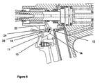
- Figures 5 and 6 illustrate an alternative embodiment of the invention.
- the air inlet 26 to the valve 12 is configured such that rotation of the valve does not affect the flow of air into the valve 12.
- the trigger 10 is in a neutral position and the valve bore 24 is aligned with the outlet 22 allowing compressed air to flow from the inlet 26 to the vacuum generator.
Landscapes
- Engineering & Computer Science (AREA)
- Mechanical Engineering (AREA)
- Portable Nailing Machines And Staplers (AREA)
- Telephone Function (AREA)
- Pens And Brushes (AREA)
- Hand Tools For Fitting Together And Separating, Or Other Hand Tools (AREA)
- Details Of Spanners, Wrenches, And Screw Drivers And Accessories (AREA)
Priority Applications (1)
| Application Number | Priority Date | Filing Date | Title |
|---|---|---|---|
| PL06710024T PL1868752T3 (pl) | 2005-04-02 | 2006-03-07 | Narzędzie do instalowania łącznika zawierające środki do unieruchomienia narzędzia |
Applications Claiming Priority (2)
| Application Number | Priority Date | Filing Date | Title |
|---|---|---|---|
| GB0506738A GB2424609B (en) | 2005-04-02 | 2005-04-02 | Fastener installation tool including means for disabling the tool |
| PCT/GB2006/000808 WO2006106286A1 (en) | 2005-04-02 | 2006-03-07 | Fastener installation tool including means for disabling the tool |
Publications (2)
| Publication Number | Publication Date |
|---|---|
| EP1868752A1 EP1868752A1 (en) | 2007-12-26 |
| EP1868752B1 true EP1868752B1 (en) | 2009-08-05 |
Family
ID=34586616
Family Applications (1)
| Application Number | Title | Priority Date | Filing Date |
|---|---|---|---|
| EP06710024A Expired - Lifetime EP1868752B1 (en) | 2005-04-02 | 2006-03-07 | Fastener installation tool including means for disabling the tool |
Country Status (17)
| Country | Link |
|---|---|
| US (1) | US7866018B2 (pl) |
| EP (1) | EP1868752B1 (pl) |
| JP (1) | JP5010580B2 (pl) |
| KR (1) | KR101022088B1 (pl) |
| CN (1) | CN100531958C (pl) |
| AT (1) | ATE438469T1 (pl) |
| AU (1) | AU2006231095B2 (pl) |
| BR (1) | BRPI0609777A2 (pl) |
| CA (1) | CA2603628C (pl) |
| DE (1) | DE602006008287D1 (pl) |
| ES (1) | ES2329168T3 (pl) |
| GB (1) | GB2424609B (pl) |
| MX (1) | MX2007012149A (pl) |
| PL (1) | PL1868752T3 (pl) |
| RU (1) | RU2371274C2 (pl) |
| WO (1) | WO2006106286A1 (pl) |
| ZA (1) | ZA200708998B (pl) |
Families Citing this family (3)
| Publication number | Priority date | Publication date | Assignee | Title |
|---|---|---|---|---|
| ITBO20070311A1 (it) * | 2007-04-27 | 2008-10-28 | Ober S P A | Pistola rivettatrice pneumoidraulica |
| GB2455730B (en) * | 2007-12-19 | 2009-12-23 | Avdel Uk Ltd | Fastener Installation Tool |
| CN103580399B (zh) * | 2013-11-07 | 2016-08-17 | 苏州汇川技术有限公司 | 伺服电机定子打铆钉装置及工艺 |
Family Cites Families (17)
| Publication number | Priority date | Publication date | Assignee | Title |
|---|---|---|---|---|
| DE2537792C3 (de) * | 1975-08-25 | 1986-11-13 | Alfred Honsel Nieten - und Metallwarenfabrik GmbH & Co, 5758 Fröndenberg | Blindnietgerät |
| US4118969A (en) * | 1977-07-27 | 1978-10-10 | Huck Manufacturing Company | Double action fastener installation tool for blind rivets and the like |
| GB2130514B (en) * | 1982-11-18 | 1985-10-23 | Spurway Cooke Ind Pty Ltd | Blind-rivet setting tool |
| US4517820A (en) * | 1983-06-22 | 1985-05-21 | Usm Corporation | Blind rivet tool |
| US4598571A (en) * | 1984-04-02 | 1986-07-08 | Usm Corporation | Control valve for a mandrel collection system |
| DE3603421A1 (de) * | 1986-02-05 | 1987-08-06 | Schwab Maschbau | Betaetigungseinrichtung fuer nietsetzwerkzeug |
| EP0302128B1 (de) * | 1987-08-04 | 1992-01-02 | Maschinenbau Subotsch & Schwab Gmbh | Nietsetzwerkzeug zum Setzen von Blindnieten |
| US5031508A (en) * | 1990-09-05 | 1991-07-16 | Emhart Inc. | Rivet setting tool |
| JP2918362B2 (ja) * | 1990-09-05 | 1999-07-12 | エムハート インコーポレイテッド | リベット固定工具 |
| CZ2272U1 (cs) * | 1993-06-11 | 1994-08-05 | Josef Wihan | Nýtovací nástroj |
| GB2301547A (en) * | 1995-06-02 | 1996-12-11 | Avdel Systems Ltd | Fastener installation tool |
| AU8237898A (en) * | 1997-07-28 | 1999-02-16 | Ober Utensili Pneumatici S.R.L. | Pneumatic-hydraulic rivet gun |
| DE29822652U1 (de) * | 1998-12-22 | 2000-05-18 | MS Verwaltungs- und Patentgesellschaft mbH., 49084 Osnabrück | Nietwerkzeug |
| GB9923266D0 (en) * | 1999-10-02 | 1999-12-08 | Textron Fastening Syst Ltd | Riveting apparatus |
| RU17881U1 (ru) * | 2001-01-18 | 2001-05-10 | Клычев Владимир Федорович | Устройство для забивки спиц |
| GB2394686B (en) * | 2001-02-21 | 2004-10-06 | Textron Fastening Syst Ltd | Fastener installation tool including fastener-parts collection means |
| US6532635B1 (en) * | 2002-03-01 | 2003-03-18 | Huck International, Inc. | Installation tool for pull type fasteners |
-
2005
- 2005-04-02 GB GB0506738A patent/GB2424609B/en not_active Expired - Lifetime
-
2006
- 2006-03-07 US US11/909,688 patent/US7866018B2/en not_active Expired - Fee Related
- 2006-03-07 AU AU2006231095A patent/AU2006231095B2/en not_active Ceased
- 2006-03-07 BR BRPI0609777-4A patent/BRPI0609777A2/pt not_active IP Right Cessation
- 2006-03-07 WO PCT/GB2006/000808 patent/WO2006106286A1/en not_active Ceased
- 2006-03-07 AT AT06710024T patent/ATE438469T1/de not_active IP Right Cessation
- 2006-03-07 KR KR1020077022495A patent/KR101022088B1/ko not_active Expired - Fee Related
- 2006-03-07 CN CNB2006800106315A patent/CN100531958C/zh not_active Expired - Fee Related
- 2006-03-07 DE DE602006008287T patent/DE602006008287D1/de not_active Expired - Lifetime
- 2006-03-07 EP EP06710024A patent/EP1868752B1/en not_active Expired - Lifetime
- 2006-03-07 RU RU2007140676/02A patent/RU2371274C2/ru not_active IP Right Cessation
- 2006-03-07 CA CA2603628A patent/CA2603628C/en not_active Expired - Fee Related
- 2006-03-07 ES ES06710024T patent/ES2329168T3/es not_active Expired - Lifetime
- 2006-03-07 JP JP2008503569A patent/JP5010580B2/ja not_active Expired - Fee Related
- 2006-03-07 MX MX2007012149A patent/MX2007012149A/es active IP Right Grant
- 2006-03-07 PL PL06710024T patent/PL1868752T3/pl unknown
-
2007
- 2007-10-19 ZA ZA200708998A patent/ZA200708998B/xx unknown
Also Published As
| Publication number | Publication date |
|---|---|
| RU2371274C2 (ru) | 2009-10-27 |
| JP5010580B2 (ja) | 2012-08-29 |
| WO2006106286A1 (en) | 2006-10-12 |
| CN101151112A (zh) | 2008-03-26 |
| GB2424609B (en) | 2007-10-24 |
| US7866018B2 (en) | 2011-01-11 |
| ES2329168T3 (es) | 2009-11-23 |
| MX2007012149A (es) | 2008-03-10 |
| US20100139068A1 (en) | 2010-06-10 |
| EP1868752A1 (en) | 2007-12-26 |
| ZA200708998B (en) | 2008-11-26 |
| AU2006231095A1 (en) | 2006-10-12 |
| DE602006008287D1 (de) | 2009-09-17 |
| PL1868752T3 (pl) | 2009-10-30 |
| BRPI0609777A2 (pt) | 2011-10-18 |
| KR101022088B1 (ko) | 2011-03-17 |
| GB2424609A (en) | 2006-10-04 |
| AU2006231095B2 (en) | 2011-03-10 |
| RU2007140676A (ru) | 2009-05-10 |
| JP2008534285A (ja) | 2008-08-28 |
| KR20080007318A (ko) | 2008-01-18 |
| ATE438469T1 (de) | 2009-08-15 |
| GB0506738D0 (en) | 2005-05-11 |
| CN100531958C (zh) | 2009-08-26 |
| CA2603628A1 (en) | 2006-10-12 |
| CA2603628C (en) | 2011-05-10 |
Similar Documents
| Publication | Publication Date | Title |
|---|---|---|
| JP4083383B2 (ja) | 空気圧―作動油圧リベットガン | |
| KR100843291B1 (ko) | 스웨이지 타입의 나사 화스너 설치용 설치 도구 | |
| AU2017284889B2 (en) | Pneumatic nail gun with safety control chamber | |
| EP1590130B1 (en) | Fastener driving tool with removable contact member and method of exchanging contact members | |
| EP0218641B1 (en) | Offset tool and cartridge nose assembly | |
| EP1169163A1 (en) | Safety trip assembly and trip lock mechanism for a fastener driving tool | |
| CN1929959A (zh) | 手持式工具机 | |
| EP2500139A1 (en) | Pneumatic ratchet wrench with a pneumatically actuated reversing device | |
| US7124837B2 (en) | Pneumatic motor trigger actuator | |
| EP0381327B1 (en) | Control valve for a mandrel collection system | |
| EP1868752B1 (en) | Fastener installation tool including means for disabling the tool | |
| US7290317B2 (en) | Blind rivet setting tool | |
| EP0571110B1 (en) | Riveting apparatus | |
| EP1402974A3 (en) | A rivet gun for threaded rivets | |
| CA1300564C (en) | Hydropneumatic gun for setting blind-rivet nuts | |
| US20030034467A1 (en) | Automatic vacuum shut-off/noise reduction device | |
| JP2006346807A (ja) | エアインパクトレンチ | |
| CZ15642U1 (cs) | Pneumaticko hydraulický nýtovací nástroj |
Legal Events
| Date | Code | Title | Description |
|---|---|---|---|
| PUAI | Public reference made under article 153(3) epc to a published international application that has entered the european phase |
Free format text: ORIGINAL CODE: 0009012 |
|
| 17P | Request for examination filed |
Effective date: 20070928 |
|
| AK | Designated contracting states |
Kind code of ref document: A1 Designated state(s): AT BE BG CH CY CZ DE DK EE ES FI FR GB GR HU IE IS IT LI LT LU LV MC NL PL PT RO SE SI SK TR |
|
| 17Q | First examination report despatched |
Effective date: 20080429 |
|
| DAX | Request for extension of the european patent (deleted) | ||
| GRAP | Despatch of communication of intention to grant a patent |
Free format text: ORIGINAL CODE: EPIDOSNIGR1 |
|
| GRAS | Grant fee paid |
Free format text: ORIGINAL CODE: EPIDOSNIGR3 |
|
| GRAA | (expected) grant |
Free format text: ORIGINAL CODE: 0009210 |
|
| RIN1 | Information on inventor provided before grant (corrected) |
Inventor name: DEAR, AIDEN |
|
| AK | Designated contracting states |
Kind code of ref document: B1 Designated state(s): AT BE BG CH CY CZ DE DK EE ES FI FR GB GR HU IE IS IT LI LT LU LV MC NL PL PT RO SE SI SK TR |
|
| REG | Reference to a national code |
Ref country code: GB Ref legal event code: FG4D |
|
| REG | Reference to a national code |
Ref country code: CH Ref legal event code: EP |
|
| REG | Reference to a national code |
Ref country code: IE Ref legal event code: FG4D |
|
| REF | Corresponds to: |
Ref document number: 602006008287 Country of ref document: DE Date of ref document: 20090917 Kind code of ref document: P |
|
| REG | Reference to a national code |
Ref country code: SE Ref legal event code: TRGR |
|
| REG | Reference to a national code |
Ref country code: PL Ref legal event code: T3 |
|
| REG | Reference to a national code |
Ref country code: ES Ref legal event code: FG2A Ref document number: 2329168 Country of ref document: ES Kind code of ref document: T3 |
|
| LTIE | Lt: invalidation of european patent or patent extension |
Effective date: 20090805 |
|
| PG25 | Lapsed in a contracting state [announced via postgrant information from national office to epo] |
Ref country code: LT Free format text: LAPSE BECAUSE OF FAILURE TO SUBMIT A TRANSLATION OF THE DESCRIPTION OR TO PAY THE FEE WITHIN THE PRESCRIBED TIME-LIMIT Effective date: 20090805 Ref country code: IS Free format text: LAPSE BECAUSE OF FAILURE TO SUBMIT A TRANSLATION OF THE DESCRIPTION OR TO PAY THE FEE WITHIN THE PRESCRIBED TIME-LIMIT Effective date: 20091205 Ref country code: AT Free format text: LAPSE BECAUSE OF FAILURE TO SUBMIT A TRANSLATION OF THE DESCRIPTION OR TO PAY THE FEE WITHIN THE PRESCRIBED TIME-LIMIT Effective date: 20090805 Ref country code: FI Free format text: LAPSE BECAUSE OF FAILURE TO SUBMIT A TRANSLATION OF THE DESCRIPTION OR TO PAY THE FEE WITHIN THE PRESCRIBED TIME-LIMIT Effective date: 20090805 |
|
| NLV1 | Nl: lapsed or annulled due to failure to fulfill the requirements of art. 29p and 29m of the patents act | ||
| PG25 | Lapsed in a contracting state [announced via postgrant information from national office to epo] |
Ref country code: NL Free format text: LAPSE BECAUSE OF FAILURE TO SUBMIT A TRANSLATION OF THE DESCRIPTION OR TO PAY THE FEE WITHIN THE PRESCRIBED TIME-LIMIT Effective date: 20090805 Ref country code: LV Free format text: LAPSE BECAUSE OF FAILURE TO SUBMIT A TRANSLATION OF THE DESCRIPTION OR TO PAY THE FEE WITHIN THE PRESCRIBED TIME-LIMIT Effective date: 20090805 Ref country code: SI Free format text: LAPSE BECAUSE OF FAILURE TO SUBMIT A TRANSLATION OF THE DESCRIPTION OR TO PAY THE FEE WITHIN THE PRESCRIBED TIME-LIMIT Effective date: 20090805 |
|
| PG25 | Lapsed in a contracting state [announced via postgrant information from national office to epo] |
Ref country code: BG Free format text: LAPSE BECAUSE OF FAILURE TO SUBMIT A TRANSLATION OF THE DESCRIPTION OR TO PAY THE FEE WITHIN THE PRESCRIBED TIME-LIMIT Effective date: 20091105 Ref country code: PT Free format text: LAPSE BECAUSE OF FAILURE TO SUBMIT A TRANSLATION OF THE DESCRIPTION OR TO PAY THE FEE WITHIN THE PRESCRIBED TIME-LIMIT Effective date: 20091205 |
|
| PG25 | Lapsed in a contracting state [announced via postgrant information from national office to epo] |
Ref country code: EE Free format text: LAPSE BECAUSE OF FAILURE TO SUBMIT A TRANSLATION OF THE DESCRIPTION OR TO PAY THE FEE WITHIN THE PRESCRIBED TIME-LIMIT Effective date: 20090805 Ref country code: RO Free format text: LAPSE BECAUSE OF FAILURE TO SUBMIT A TRANSLATION OF THE DESCRIPTION OR TO PAY THE FEE WITHIN THE PRESCRIBED TIME-LIMIT Effective date: 20090805 Ref country code: DK Free format text: LAPSE BECAUSE OF FAILURE TO SUBMIT A TRANSLATION OF THE DESCRIPTION OR TO PAY THE FEE WITHIN THE PRESCRIBED TIME-LIMIT Effective date: 20090805 |
|
| PG25 | Lapsed in a contracting state [announced via postgrant information from national office to epo] |
Ref country code: SK Free format text: LAPSE BECAUSE OF FAILURE TO SUBMIT A TRANSLATION OF THE DESCRIPTION OR TO PAY THE FEE WITHIN THE PRESCRIBED TIME-LIMIT Effective date: 20090805 |
|
| PLBE | No opposition filed within time limit |
Free format text: ORIGINAL CODE: 0009261 |
|
| STAA | Information on the status of an ep patent application or granted ep patent |
Free format text: STATUS: NO OPPOSITION FILED WITHIN TIME LIMIT |
|
| PG25 | Lapsed in a contracting state [announced via postgrant information from national office to epo] |
Ref country code: BE Free format text: LAPSE BECAUSE OF FAILURE TO SUBMIT A TRANSLATION OF THE DESCRIPTION OR TO PAY THE FEE WITHIN THE PRESCRIBED TIME-LIMIT Effective date: 20090805 |
|
| 26N | No opposition filed |
Effective date: 20100507 |
|
| PG25 | Lapsed in a contracting state [announced via postgrant information from national office to epo] |
Ref country code: MC Free format text: LAPSE BECAUSE OF NON-PAYMENT OF DUE FEES Effective date: 20100331 Ref country code: GR Free format text: LAPSE BECAUSE OF FAILURE TO SUBMIT A TRANSLATION OF THE DESCRIPTION OR TO PAY THE FEE WITHIN THE PRESCRIBED TIME-LIMIT Effective date: 20091106 |
|
| REG | Reference to a national code |
Ref country code: CH Ref legal event code: PL |
|
| PG25 | Lapsed in a contracting state [announced via postgrant information from national office to epo] |
Ref country code: IE Free format text: LAPSE BECAUSE OF NON-PAYMENT OF DUE FEES Effective date: 20100307 |
|
| PG25 | Lapsed in a contracting state [announced via postgrant information from national office to epo] |
Ref country code: CH Free format text: LAPSE BECAUSE OF NON-PAYMENT OF DUE FEES Effective date: 20100331 Ref country code: LI Free format text: LAPSE BECAUSE OF NON-PAYMENT OF DUE FEES Effective date: 20100331 |
|
| PGFP | Annual fee paid to national office [announced via postgrant information from national office to epo] |
Ref country code: IT Payment date: 20120327 Year of fee payment: 7 |
|
| PG25 | Lapsed in a contracting state [announced via postgrant information from national office to epo] |
Ref country code: CY Free format text: LAPSE BECAUSE OF FAILURE TO SUBMIT A TRANSLATION OF THE DESCRIPTION OR TO PAY THE FEE WITHIN THE PRESCRIBED TIME-LIMIT Effective date: 20090805 |
|
| PG25 | Lapsed in a contracting state [announced via postgrant information from national office to epo] |
Ref country code: HU Free format text: LAPSE BECAUSE OF FAILURE TO SUBMIT A TRANSLATION OF THE DESCRIPTION OR TO PAY THE FEE WITHIN THE PRESCRIBED TIME-LIMIT Effective date: 20100206 Ref country code: LU Free format text: LAPSE BECAUSE OF NON-PAYMENT OF DUE FEES Effective date: 20100307 |
|
| PG25 | Lapsed in a contracting state [announced via postgrant information from national office to epo] |
Ref country code: TR Free format text: LAPSE BECAUSE OF FAILURE TO SUBMIT A TRANSLATION OF THE DESCRIPTION OR TO PAY THE FEE WITHIN THE PRESCRIBED TIME-LIMIT Effective date: 20090805 |
|
| PGFP | Annual fee paid to national office [announced via postgrant information from national office to epo] |
Ref country code: GB Payment date: 20130326 Year of fee payment: 8 Ref country code: SE Payment date: 20130326 Year of fee payment: 8 Ref country code: CZ Payment date: 20130222 Year of fee payment: 8 Ref country code: DE Payment date: 20130327 Year of fee payment: 8 |
|
| PGFP | Annual fee paid to national office [announced via postgrant information from national office to epo] |
Ref country code: PL Payment date: 20130305 Year of fee payment: 8 |
|
| PGFP | Annual fee paid to national office [announced via postgrant information from national office to epo] |
Ref country code: ES Payment date: 20120328 Year of fee payment: 7 |
|
| PGFP | Annual fee paid to national office [announced via postgrant information from national office to epo] |
Ref country code: FR Payment date: 20130429 Year of fee payment: 8 |
|
| REG | Reference to a national code |
Ref country code: DE Ref legal event code: R119 Ref document number: 602006008287 Country of ref document: DE |
|
| PG25 | Lapsed in a contracting state [announced via postgrant information from national office to epo] |
Ref country code: CZ Free format text: LAPSE BECAUSE OF NON-PAYMENT OF DUE FEES Effective date: 20140307 |
|
| REG | Reference to a national code |
Ref country code: SE Ref legal event code: EUG |
|
| GBPC | Gb: european patent ceased through non-payment of renewal fee |
Effective date: 20140307 |
|
| PG25 | Lapsed in a contracting state [announced via postgrant information from national office to epo] |
Ref country code: SE Free format text: LAPSE BECAUSE OF NON-PAYMENT OF DUE FEES Effective date: 20140308 |
|
| REG | Reference to a national code |
Ref country code: FR Ref legal event code: ST Effective date: 20141128 |
|
| REG | Reference to a national code |
Ref country code: DE Ref legal event code: R119 Ref document number: 602006008287 Country of ref document: DE Effective date: 20141001 |
|
| PG25 | Lapsed in a contracting state [announced via postgrant information from national office to epo] |
Ref country code: DE Free format text: LAPSE BECAUSE OF NON-PAYMENT OF DUE FEES Effective date: 20141001 Ref country code: FR Free format text: LAPSE BECAUSE OF NON-PAYMENT OF DUE FEES Effective date: 20140331 Ref country code: GB Free format text: LAPSE BECAUSE OF NON-PAYMENT OF DUE FEES Effective date: 20140307 |
|
| PG25 | Lapsed in a contracting state [announced via postgrant information from national office to epo] |
Ref country code: IT Free format text: LAPSE BECAUSE OF NON-PAYMENT OF DUE FEES Effective date: 20140307 |
|
| PG25 | Lapsed in a contracting state [announced via postgrant information from national office to epo] |
Ref country code: PL Free format text: LAPSE BECAUSE OF NON-PAYMENT OF DUE FEES Effective date: 20140307 |
|
| REG | Reference to a national code |
Ref country code: PL Ref legal event code: LAPE |
|
| REG | Reference to a national code |
Ref country code: ES Ref legal event code: FD2A Effective date: 20150729 |
|
| PG25 | Lapsed in a contracting state [announced via postgrant information from national office to epo] |
Ref country code: ES Free format text: LAPSE BECAUSE OF NON-PAYMENT OF DUE FEES Effective date: 20140308 |