EP1868744B1 - Device and method for preventing the drying of fluid products in a dispensing machine for such products - Google Patents
Device and method for preventing the drying of fluid products in a dispensing machine for such products Download PDFInfo
- Publication number
- EP1868744B1 EP1868744B1 EP06725535A EP06725535A EP1868744B1 EP 1868744 B1 EP1868744 B1 EP 1868744B1 EP 06725535 A EP06725535 A EP 06725535A EP 06725535 A EP06725535 A EP 06725535A EP 1868744 B1 EP1868744 B1 EP 1868744B1
- Authority
- EP
- European Patent Office
- Prior art keywords
- delivery
- conditioning
- delivery nozzles
- space
- nozzles
- Prior art date
- Legal status (The legal status is an assumption and is not a legal conclusion. Google has not performed a legal analysis and makes no representation as to the accuracy of the status listed.)
- Expired - Lifetime
Links
Images

Classifications
-
- B—PERFORMING OPERATIONS; TRANSPORTING
- B08—CLEANING
- B08B—CLEANING IN GENERAL; PREVENTION OF FOULING IN GENERAL
- B08B3/00—Cleaning by methods involving the use or presence of liquid or steam
-
- B—PERFORMING OPERATIONS; TRANSPORTING
- B05—SPRAYING OR ATOMISING IN GENERAL; APPLYING FLUENT MATERIALS TO SURFACES, IN GENERAL
- B05B—SPRAYING APPARATUS; ATOMISING APPARATUS; NOZZLES
- B05B15/00—Details of spraying plant or spraying apparatus not otherwise provided for; Accessories
- B05B15/50—Arrangements for cleaning; Arrangements for preventing deposits, drying-out or blockage; Arrangements for detecting improper discharge caused by the presence of foreign matter
-
- B—PERFORMING OPERATIONS; TRANSPORTING
- B08—CLEANING
- B08B—CLEANING IN GENERAL; PREVENTION OF FOULING IN GENERAL
- B08B2230/00—Other cleaning aspects applicable to all B08B range
- B08B2230/01—Cleaning with steam
Definitions
- the present invention concerns a device and a method for preventing the drying of fluid products, such as for example coloring liquids, bases for paints, varnishes, enamels, inks and suchlike, in a dispensing machine for such products.
- the device is able to be advantageously applied in correspondence with the nozzles of a delivery head of the dispensing machine, and allows to keep specific dyes of different nature, flowing into the same delivery head, at controlled temperature and humidity.
- Known dispensing or distributing machines for fluid products such as for example dyes of different shade or color, able to be dosed and/or added to a basic substance so as to form a paint of a determinate color, comprise a plurality of delivery nozzles, of variable number, from some units to some tens, which are grouped together in a delivery head.
- Each delivery nozzle is connected to a corresponding tank containing a determinate dye and is controlled by an electro-pump which cause the selective delivery of the fluid product in a quantity appropriately chosen, for example with the aid of an electronic processor.
- a device is known, described in WO-A-2005/107956 , filed on 10.05.2005 in the name of the present Applicant.
- This known device is able to be associated with the delivery head, to keep the terminal parts of the delivery nozzles at a controlled temperature and level of humidity, so as to prevent the drying of the fluid products which are not delivered frequently, limiting the errors in measurement of the quantities delivered and the possible introduction of coagulated particles, which cannot be mixed, into the collection container of the finished product.
- EP-A-1.510.260 published on 02.03.2005 discloses a device according to the preamble of claim 1 and a method according to the preamble of claim 8.
- Producers of paints and varnishes increasingly feel the need to have a delivery head with a high number of nozzles, for example 24 or 32, divided into two or more groups, so as to deliver different types of dyes, such as for example universal dyes, industrial dyes with organic solvents, or decorative dyes, such as water dyes without VOCs (Volatile Organic Components).
- dyes such as for example universal dyes, industrial dyes with organic solvents, or decorative dyes, such as water dyes without VOCs (Volatile Organic Components).
- known devices are not able to guarantee optimum humidification for the different groups of delivery nozzles, since the products delivered by each group have different characteristics and they must be humidified and preserved with different parameters and/or by means of different conditioning fluids, for example steam for water dyes and universal dyes and organic solvents for solvent dyes.
- This disadvantage can also cause part of the products delivered to dry out, thus making some of the problems previously solved re-surface, such as the difficulty in measuring the delivery and the poor quality of the finished product.
- One purpose of the present invention is to achieve a device, and to perfect a method, which prevent the drying of fluid products, also when the same delivery head is provided with different groups of nozzles, able to deliver fluid products with different characteristics.
- Another purpose of the present invention is to achieve a device which is simple and economic to make and to use.
- a device for preventing the drying of fluid products according to the present invention is able to be applied in a delivery head of a dispensing machine for fluid products, in which the delivery head is provided with a plurality of delivery nozzles.
- the device comprises first means able to generate at least a conditioning flow, second means able to convey the conditioning flow towards a space underneath the delivery nozzles and create therein at least an atmosphere different from that of the environment where the dispensing machine is to be found when in use.
- the space underneath the delivery nozzles is divided into at least two distinct conditioning zones, which are disposed in correspondence with an equal number of groups of delivery nozzles, and in which different atmospheres are able to be created, according to the type of fluid product delivered by the corresponding group of delivery nozzles.
- each fluid product able to be delivered is maintained in its optimum conditions of humidification and preservation, guaranteeing optimum quality of the finished product, and allowing to quantify with accuracy the quantity of product delivered for each individual delivery nozzle.
- the solution according to the present invention is simple and economic to make and therefore, to the operating advantages explained above, we add also a reduction in production costs and times, and also a considerable ease of use.
- the space underneath the nozzles is at least partly closable by means of covering means, which comprises closing and conditioning elements able to define, in cooperation with determinate conditioning zones, closed chambers with a specific atmosphere according to the type of fluid product delivered by the corresponding group of delivery nozzles.
- the device also comprises detection means, disposed in proximity with the conditioning zones and able to detect one or more significant parameters of the relative atmosphere, and regulation means able to regulate one or more characteristics of the conditioning flow, according to the values detected by the detection means, in order to maintain the significant parameters of the determinate atmosphere inside a set of predetermined values.
- Said detection means preferably comprises sensors of a known type, able to detect the conditions of relative humidity (RH%) and temperature (°C) around the respective conditioning zone.
- the sensors are connected to a control circuit, for example electronic, able to command said first means, in order to generate a conditioning flow having predeterminate values of humidity, temperature and/or delivery, comprised between lower and upper limit values.
- each delivery nozzle comprises a terminal part provided with an inner channel of limited length, with a conical terminal shape, converging towards the inside, so as to reduce the losses of load and to improve the dosage of the fluid product in its minimum quantities, facilitating the detachment thereof.
- the compartment 19 defined under the delivery head 12 is selectively closable by means of a covering stopper 40.
- thirty-two delivery nozzles 11 are provided on the delivery head 12, facing into the compartment 19 and divided into four groups of eight nozzles 11 each. From every group a different fluid product is able to be delivered, such as for example universal dyes, organic-solvent industrial dyes, water dyes without VOCs, and others.
- First two groups of delivery nozzles 11 are able to deliver organic-solvent dyes, while second two groups of delivery nozzles 11 are able to deliver water dyes.
- Each delivery nozzle 11 has a dosing pipe 11a and a terminal element 11b, in order to dose the fluid product to be delivered.
- each terminal element 11b is substantially tubular in shape and is shaped conical at the dosing end so as to reduce the attachment section of the fluid product to be delivered in the immediate proximity of the delivery head 12. In this way, the detachment of the fluid product is encouraged, the accuracy of dosing is increased even with small quantities of fluid product and, thanks to the limited length of the tubular element 11b, the losses of load induced are also minimal.
- each terminal element 11b of the delivery nozzles 11 also allows to simplify the connection with the dosing pipe 11b since, in this case, the connection is effected with a simple binding band, of a known type and not shown here.
- the compartment 19 is divided, in this case, into four conditioning zones, respectively 19a, 19b, 19c and 19d, substantially equal to each other and from each of which a group of eight delivery nozzles 11 emerges.
- the nozzles 11 of the groups delivering organic-solvent dyes emerge from the zone 19a and from the zone 19b whereas the nozzles 11 delivering water dyes or universal dyes emerge from zone 19c and zone 19d.
- the conditioning zones 19a, 19b, 19c and 19d are separated from each other by four dividing walls 16, which are made in a piece on the lower surface of the delivery head 12 and are disposed substantially orthogonal with respect to each other.
- annular passage 20 is provided, advantageously between some tenths of a millimeter and a millimeter wide.
- the annular passage can advantageously be interrupted radially, in correspondence with the dividing walls 16.
- one end 21a of a pipe 21 is inserted, having the other end 21b connected to a steam generator device 25, only shown schematically in fig. 1 .
- the steam generator 25 is connected to a control unit 29, for example of the electronic type and provided with a microprocessor, which is able to regulate both the quantity and the temperature of the steam delivered.
- a group of sensors 30 is disposed, of a known type, which is able to detect the percentage of relative humidity (RH%) and temperature (°C) of the fluid present therein and to transmit corresponding electric signals to a control unit 29.
- the group of sensors 30 can in any case send signals to the control unit 29, even during the period of inactivity of the dispensing machine, so as to signal possible anomalies of the covering stopper 40, when the chamber is closed, humidification of every group of delivery nozzles 11, and possibly cause the activation of alarms and/or automatic corrective operations, for example topping up the humidification tank of the steam generator 25.
- the control unit 29 coordinates and regulates the production and the temperature of the steam, so that inside each conditioning zone 19c and 19d (universal and water dyes) determinate levels of humidity and temperature are maintained, which guarantee that unused fluid products are maintained without drying, in any operating condition of the machine.
- each conditioning zone 19c and 19d universalal and water dyes
- control unit 29 can vary the physical and/or chemical characteristics of the flow introduced into the annular chamber 15.
- both the temperature and quantity of flow introduced can be increased or reduced, so as to vary, for example, the partial pressure in the individual zones 19c and 19d, in order to prevent dew point from being reached.
- the control unit 29 can possibly be integrated into the circuitry of the dispensing machine itself, thus also allowing to easily integrate the device 10 with known systems for humidifying the delivery nozzles 11 during the periods of inactivity of the dispensing machine. In fact, it is sufficient to dispose sensor means, for example of a mechanical, optical, magnetic type or suchlike, able to detect the inactivity of the dispensing machine and/or the presence or absence in correspondence with the delivery head 12 of the covering device 40 of the machine.
- the covering stopper 40 is selectively able to be associated with the lower part of the delivery head 12 and is able to create a closed chamber with humid atmosphere obtained by micro-capillarity and with organic solvents in order to condition in correspondence with the zones 19a and 19b where the delivery nozzles 11 for organic-solvent dyes are provided, and an open chamber in correspondence with the conditioning zones 19c and 19d where the delivery nozzles 11 for water dyes are provided.
- the covering stopper 40 comprises, in correspondence with the two conditioning zones 19a and 19b, a felt 41, soaked in organic solvents and kept damp by means of micro- filtration which, when the covering stopper 40 is disposed below the delivery head 12, determines the air-tight closure of said two conditioning zones 19a and 19b.
- the felt 41 defines inside the two conditioning zones 19a and 19b a desired atmosphere saturated with organic solvents.
- the felt 41 is provided with a tail 41a, which is partly immersed, in known manner, in a container containing a conditioning fluid as described in the above-mentioned European patent application EP-A-1.510.260 .
- the control unit 29, under any operating condition of the dispensing machine, is able to manage the different components of the device 10, so as to obtain and guarantee the best conditions for preserving the dyes in the zones 19c and 19d.
- the covering stopper 40 of the delivery head 12, with the dispensing machine in inactive condition, is closed, and maintains the desired atmosphere saturated with organic solvents in the conditioning zones 19a and 19b through the micro-filtration system.
- the covering stopper 40 comprises in correspondence with the conditioning zones 19c and 19d a through aperture 42, which allows to maintain optimum conditions of preserving the conditioning parameters also during the dosing steps.
- the device 10 as described heretofore functions as follows.
- the optimum levels, comprised between maximum and minimum values, of the significant parameters of the flow, that is, those relating to the relative humidity and temperature, are pre-determined and obtained under the control of the control unit 29.
- the flow of air mixed with steam is introduced into the conditioning zones 19c and 19d through the annular passage 20, in a substantially radial and angled manner, advantageously orthogonal to the direction of delivery of the fluid products through the delivery nozzles 11.
- determinate atmospheres are created having different rates of humidity (RH%) and temperature (°C).
- the sensor group 30 continuously detects the actual values of humidity and temperature inside the conditioning zones 19c and 19d, and transmits, in feedback, the values detected to the control unit 29, which possibly modifies the conditions under which the flows are generated, so that the values of the significant parameters are always comprised within the predetermined limit values.
- the parameters that can be controlled also comprise, for example but not only, physical and chemical characteristics of the air and/or steam present in the various conditioning zones 19c and 19d, like the relative or partial pressure.
- the control unit 29 can act in feedback, to modify the environmental conditions. Some particularly significant but non-limiting examples are: temperature, partial pressure, titer, volume and quantity of the solvent introduced, relative humidity of the mixture of air and steam introduced, introduction rate and, in general, one or more physical and/or chemical characteristics of the solvent, the steam or the mixture of air and steam introduced into the conditioning zone of the relative group of nozzles 11.
- control unit 29 controls whether the air around the conditioning zones 19c and 19d of every group of delivery nozzles 11 is saturated or near saturation. If so, the control unit 29 corrects in feedback the environmental conditions around the various groups of delivery nozzles 11, for example, by raising the temperature or lowering the relative humidity of the flow in the relative conditioning zones 19c and 19d.
- the felt 41 of the covering stopper 40 can extend only for a quarter of the total surface, and completely close only one conditioning zone 19b.
- the felts 41 instead of having a segmented shape as in the previous cases, the felts 41 have a substantially circumferential shape.
- the felts 41 can have a shape and disposition corresponding to the distribution of the groups of delivery nozzles 11 in the delivery head 12.
Landscapes
- Coating Apparatus (AREA)
- Drying Of Solid Materials (AREA)
- Loading And Unloading Of Fuel Tanks Or Ships (AREA)
- Details Or Accessories Of Spraying Plant Or Apparatus (AREA)
- Application Of Or Painting With Fluid Materials (AREA)
- Vending Machines For Individual Products (AREA)
Abstract
Description
- The present invention concerns a device and a method for preventing the drying of fluid products, such as for example coloring liquids, bases for paints, varnishes, enamels, inks and suchlike, in a dispensing machine for such products. The device is able to be advantageously applied in correspondence with the nozzles of a delivery head of the dispensing machine, and allows to keep specific dyes of different nature, flowing into the same delivery head, at controlled temperature and humidity.
- Known dispensing or distributing machines for fluid products, such as for example dyes of different shade or color, able to be dosed and/or added to a basic substance so as to form a paint of a determinate color, comprise a plurality of delivery nozzles, of variable number, from some units to some tens, which are grouped together in a delivery head. Each delivery nozzle is connected to a corresponding tank containing a determinate dye and is controlled by an electro-pump which cause the selective delivery of the fluid product in a quantity appropriately chosen, for example with the aid of an electronic processor.
- Normally, in the use of such dispensing machines, it is necessary to deliver only a few fluid products at a time, with the consequence that the fluid products, which are not delivered frequently, remain stationary in correspondence with the inactive nozzles and tend to dry out, creating problems at the moment when they need to be delivered.
- For example, a device is known, described in
WO-A-2005/107956 , filed on 10.05.2005 in the name of the present Applicant. This known device is able to be associated with the delivery head, to keep the terminal parts of the delivery nozzles at a controlled temperature and level of humidity, so as to prevent the drying of the fluid products which are not delivered frequently, limiting the errors in measurement of the quantities delivered and the possible introduction of coagulated particles, which cannot be mixed, into the collection container of the finished product. - The European patent application
EP-A-1.510.260 , published on 02.03.2005 discloses a device according to the preamble of claim 1 and a method according to the preamble of claim 8. - Producers of paints and varnishes increasingly feel the need to have a delivery head with a high number of nozzles, for example 24 or 32, divided into two or more groups, so as to deliver different types of dyes, such as for example universal dyes, industrial dyes with organic solvents, or decorative dyes, such as water dyes without VOCs (Volatile Organic Components).
- In this case, known devices are not able to guarantee optimum humidification for the different groups of delivery nozzles, since the products delivered by each group have different characteristics and they must be humidified and preserved with different parameters and/or by means of different conditioning fluids, for example steam for water dyes and universal dyes and organic solvents for solvent dyes.
- This disadvantage can also cause part of the products delivered to dry out, thus making some of the problems previously solved re-surface, such as the difficulty in measuring the delivery and the poor quality of the finished product.
- Moreover, from
US-A-5,842,641 it is known a device for moistening fluid-dispensing nozzles of a dispensing machine, and fromWO-A-03/082728 - One purpose of the present invention is to achieve a device, and to perfect a method, which prevent the drying of fluid products, also when the same delivery head is provided with different groups of nozzles, able to deliver fluid products with different characteristics.
- Another purpose of the present invention is to achieve a device which is simple and economic to make and to use.
- The Applicant has devised, tested and perfected the present invention, which brings a significant technical contribution to the state of the art, in order to obtain these and other purposes.
- The present invention is set forth and characterized in the independant claims 1 and 8, while the dependent claims describe other characteristics or variants to the main inventive idea.
- In accordance with the above purposes, a device for preventing the drying of fluid products according to the present invention is able to be applied in a delivery head of a dispensing machine for fluid products, in which the delivery head is provided with a plurality of delivery nozzles. To be more exact, the device comprises first means able to generate at least a conditioning flow, second means able to convey the conditioning flow towards a space underneath the delivery nozzles and create therein at least an atmosphere different from that of the environment where the dispensing machine is to be found when in use.
- According to a characteristic feature of the present invention, the space underneath the delivery nozzles is divided into at least two distinct conditioning zones, which are disposed in correspondence with an equal number of groups of delivery nozzles, and in which different atmospheres are able to be created, according to the type of fluid product delivered by the corresponding group of delivery nozzles.
- With the device according to the present invention, for each specific fluid product able to be delivered by the delivery head it is thus possible to create a specific conditioning atmosphere.
- In this way, each fluid product able to be delivered is maintained in its optimum conditions of humidification and preservation, guaranteeing optimum quality of the finished product, and allowing to quantify with accuracy the quantity of product delivered for each individual delivery nozzle.
- Moreover, the solution according to the present invention is simple and economic to make and therefore, to the operating advantages explained above, we add also a reduction in production costs and times, and also a considerable ease of use.
- In a preferential form of embodiment of the present invention, the space underneath the nozzles is at least partly closable by means of covering means, which comprises closing and conditioning elements able to define, in cooperation with determinate conditioning zones, closed chambers with a specific atmosphere according to the type of fluid product delivered by the corresponding group of delivery nozzles.
- Advantageously, the device according to the present invention also comprises detection means, disposed in proximity with the conditioning zones and able to detect one or more significant parameters of the relative atmosphere, and regulation means able to regulate one or more characteristics of the conditioning flow, according to the values detected by the detection means, in order to maintain the significant parameters of the determinate atmosphere inside a set of predetermined values.
- Said detection means preferably comprises sensors of a known type, able to detect the conditions of relative humidity (RH%) and temperature (°C) around the respective conditioning zone.
- The sensors are connected to a control circuit, for example electronic, able to command said first means, in order to generate a conditioning flow having predeterminate values of humidity, temperature and/or delivery, comprised between lower and upper limit values.
- In this way, it is possible to manage each conditioning zone independently, in a simple and effective manner, at the same time guaranteeing optimum humidification and preservation of the fluid products when they are not delivered and also during delivery, in the case of a steam generator.
- Advantageously, each delivery nozzle comprises a terminal part provided with an inner channel of limited length, with a conical terminal shape, converging towards the inside, so as to reduce the losses of load and to improve the dosage of the fluid product in its minimum quantities, facilitating the detachment thereof.
- These and other characteristics of the present invention will become apparent from the following description of a preferential form of embodiment, given as a non-restrictive example with reference to the attached drawings wherein:
-
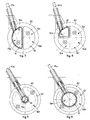
fig. 1 is a schematic perspective view from below of a device for preventing drying according to the present invention; -
fig. 2 is a cross section of the device infig. 1 ; -
fig. 3 is a plane view of a covering stopper of the device infig. 1 , having two symmetrical areas, of which the left one has the inlet of the device to transport fluid by micro-capillarity; -
fig. 4 is a first variant of the covering stopper infig. 3 , having two areas of different size, of which the upper left one has the inlet of the device to transport fluid by micro-capillarity; -
fig. 5 is a second variant of the covering stopper infig. 3 , having two concentric areas of which the smaller central one has the inlet of the device to transport fluid by micro-capillarity; -
fig. 6 is a third variant of the covering stopper infig. 3 , having two concentric areas of which the central one, which is larger in size than that infig. 5 , has the inlet of the device to transport fluid by micro-capillarity. - With reference to
figs. 1, 2 and3 , adevice 10 according to the present invention for preventing the drying of fluid products in correspondence with a plurality ofdelivery nozzles 11 of adelivery head 12 in a dispensing machine for such fluid products comprises anannular element 13 disposed substantially coaxial with thedelivery head 12 and shaped so as to define with the outer surface of thedelivery head 12 anannular chamber 15 and a space orcompartment 19, disposed under thedelivery head 12. - The
compartment 19 defined under thedelivery head 12 is selectively closable by means of acovering stopper 40. - In this case, thirty-two
delivery nozzles 11 are provided on thedelivery head 12, facing into thecompartment 19 and divided into four groups of eightnozzles 11 each. From every group a different fluid product is able to be delivered, such as for example universal dyes, organic-solvent industrial dyes, water dyes without VOCs, and others. - First two groups of
delivery nozzles 11 are able to deliver organic-solvent dyes, while second two groups ofdelivery nozzles 11 are able to deliver water dyes. - Each
delivery nozzle 11, in this case, has adosing pipe 11a and aterminal element 11b, in order to dose the fluid product to be delivered. - To be more exact, each
terminal element 11b is substantially tubular in shape and is shaped conical at the dosing end so as to reduce the attachment section of the fluid product to be delivered in the immediate proximity of thedelivery head 12. In this way, the detachment of the fluid product is encouraged, the accuracy of dosing is increased even with small quantities of fluid product and, thanks to the limited length of thetubular element 11b, the losses of load induced are also minimal. - Moreover, the shaping of each
terminal element 11b of thedelivery nozzles 11 also allows to simplify the connection with thedosing pipe 11b since, in this case, the connection is effected with a simple binding band, of a known type and not shown here. - The
compartment 19 is divided, in this case, into four conditioning zones, respectively 19a, 19b, 19c and 19d, substantially equal to each other and from each of which a group of eightdelivery nozzles 11 emerges. To be more exact, thenozzles 11 of the groups delivering organic-solvent dyes emerge from thezone 19a and from thezone 19b whereas thenozzles 11 delivering water dyes or universal dyes emerge fromzone 19c andzone 19d. - The
conditioning zones walls 16, which are made in a piece on the lower surface of thedelivery head 12 and are disposed substantially orthogonal with respect to each other. - Between the
annular chamber 15 and thecompartment 19 anannular passage 20 is provided, advantageously between some tenths of a millimeter and a millimeter wide. The annular passage can advantageously be interrupted radially, in correspondence with the dividingwalls 16. - In the
annular chamber 15, through aconnection hole 17, oneend 21a of apipe 21 is inserted, having theother end 21b connected to asteam generator device 25, only shown schematically infig. 1 . - The
steam generator 25 is connected to acontrol unit 29, for example of the electronic type and provided with a microprocessor, which is able to regulate both the quantity and the temperature of the steam delivered. - In this way it is possible to introduce into the annular chamber 15 a desired quantity of steam or a mixture of steam-saturated air which, through the
annular passage 20 enters transversely and selectively into therespective conditioning zones - In the
annular chamber 15, on the side opposite theconnection hole 17, a group ofsensors 30 is disposed, of a known type, which is able to detect the percentage of relative humidity (RH%) and temperature (°C) of the fluid present therein and to transmit corresponding electric signals to acontrol unit 29. - Moreover, preferably, the group of
sensors 30 can in any case send signals to thecontrol unit 29, even during the period of inactivity of the dispensing machine, so as to signal possible anomalies of thecovering stopper 40, when the chamber is closed, humidification of every group ofdelivery nozzles 11, and possibly cause the activation of alarms and/or automatic corrective operations, for example topping up the humidification tank of thesteam generator 25. - The
control unit 29, according to the data received from thesensor group 30, coordinates and regulates the production and the temperature of the steam, so that inside eachconditioning zone - More generally, by acting on the
steam generator 25, thecontrol unit 29 can vary the physical and/or chemical characteristics of the flow introduced into theannular chamber 15. To be more exact, both the temperature and quantity of flow introduced can be increased or reduced, so as to vary, for example, the partial pressure in theindividual zones - The
control unit 29 can possibly be integrated into the circuitry of the dispensing machine itself, thus also allowing to easily integrate thedevice 10 with known systems for humidifying thedelivery nozzles 11 during the periods of inactivity of the dispensing machine. In fact, it is sufficient to dispose sensor means, for example of a mechanical, optical, magnetic type or suchlike, able to detect the inactivity of the dispensing machine and/or the presence or absence in correspondence with thedelivery head 12 of the coveringdevice 40 of the machine. - The
covering stopper 40, as we said, is selectively able to be associated with the lower part of thedelivery head 12 and is able to create a closed chamber with humid atmosphere obtained by micro-capillarity and with organic solvents in order to condition in correspondence with thezones delivery nozzles 11 for organic-solvent dyes are provided, and an open chamber in correspondence with theconditioning zones delivery nozzles 11 for water dyes are provided. - In fact, as shown in
figs. 2 and3 , the coveringstopper 40 comprises, in correspondence with the twoconditioning zones felt 41, soaked in organic solvents and kept damp by means of micro- filtration which, when the coveringstopper 40 is disposed below thedelivery head 12, determines the air-tight closure of said twoconditioning zones conditioning zones - The felt 41 is provided with a
tail 41a, which is partly immersed, in known manner, in a container containing a conditioning fluid as described in the above-mentioned European patent applicationEP-A-1.510.260 . - The
control unit 29, under any operating condition of the dispensing machine, is able to manage the different components of thedevice 10, so as to obtain and guarantee the best conditions for preserving the dyes in thezones - The covering
stopper 40 of thedelivery head 12, with the dispensing machine in inactive condition, is closed, and maintains the desired atmosphere saturated with organic solvents in theconditioning zones - On the contrary, the covering
stopper 40 comprises in correspondence with theconditioning zones aperture 42, which allows to maintain optimum conditions of preserving the conditioning parameters also during the dosing steps. - The
device 10 as described heretofore functions as follows. - Through the
pipe 21, a flow of air mixed with steam is introduced into theannular chamber 15. - The optimum levels, comprised between maximum and minimum values, of the significant parameters of the flow, that is, those relating to the relative humidity and temperature, are pre-determined and obtained under the control of the
control unit 29. - The flow of air mixed with steam is introduced into the
conditioning zones annular passage 20, in a substantially radial and angled manner, advantageously orthogonal to the direction of delivery of the fluid products through thedelivery nozzles 11. In this way, in thevarious conditioning zones - The
sensor group 30 continuously detects the actual values of humidity and temperature inside theconditioning zones control unit 29, which possibly modifies the conditions under which the flows are generated, so that the values of the significant parameters are always comprised within the predetermined limit values. - The parameters that can be controlled also comprise, for example but not only, physical and chemical characteristics of the air and/or steam present in the
various conditioning zones control unit 29 can act in feedback, to modify the environmental conditions. Some particularly significant but non-limiting examples are: temperature, partial pressure, titer, volume and quantity of the solvent introduced, relative humidity of the mixture of air and steam introduced, introduction rate and, in general, one or more physical and/or chemical characteristics of the solvent, the steam or the mixture of air and steam introduced into the conditioning zone of the relative group ofnozzles 11. - To be more exact, the
control unit 29 controls whether the air around theconditioning zones delivery nozzles 11 is saturated or near saturation. If so, thecontrol unit 29 corrects in feedback the environmental conditions around the various groups ofdelivery nozzles 11, for example, by raising the temperature or lowering the relative humidity of the flow in therelative conditioning zones - It is clear that modifications and/or additions of parts or steps may be made to the
device 10 and the method as described heretofore, without departing from the scope of the present invention. - For example, according to the variant shown in
fig. 4 , if only one quarter of thedelivery nozzles 11 provided on thedelivery head 12 are able to deliver an organic solvent dye, the felt 41 of the coveringstopper 40 can extend only for a quarter of the total surface, and completely close only oneconditioning zone 19b. - In the solutions shown in
figs. 5 and 6 , instead of having a segmented shape as in the previous cases, thefelts 41 have a substantially circumferential shape. - In general, it comes within the scope of the present invention to provide that the
felts 41 can have a shape and disposition corresponding to the distribution of the groups ofdelivery nozzles 11 in thedelivery head 12. - It is also clear that, although the present invention has been described with reference to a specific example, a person of skill in the art shall certainly be able to achieve many other equivalent forms of device and method, having the characteristics as set forth in the claims and hence all coming within the field of protection defined thereby.
Claims (8)
- Device for preventing the drying of fluid products in a delivery head (12) of a machine for dispensing said fluid products, wherein said delivery head (12) is provided with a plurality of delivery nozzles (11) divided into at least two groups, said device comprising first means (25) able to generate at least a conditioning flow, second means (15, 20, 21) able to convey said conditioning flow towards a space (19) underneath said delivery nozzles (11) and create in said space (19) at least an atmosphere different from that of the environment in which said dispensing machine is to be found during use, characterized in that said space (19) is divided into at least two distinct conditioning zones (19a, 19b, 19c, 19d), disposed in correspondence with said groups of said delivery nozzles (11), and in which different atmospheres are able to be created, according to the type of fluid product delivered by the corresponding group of delivery nozzles (11).
- Device as in claim 1, characterized in that it also comprises covering means (40) able to selectively close at least partly said space (19) underneath said delivery nozzles (11).
- Device as in claim 2, characterized in that said covering means (40) comprises at least a closing and conditioning element (41) able to define, in cooperation with a determinate conditioning zone (19a, 19b), a corresponding closed chamber with a saturated atmosphere due to micro-filtration, according to the type of fluid product delivered by the corresponding group of delivery nozzles (11).
- Device as in claim 1 or 2, characterized in that said first means comprises at least a generator member (25) able to generate a flow of air mixed with steam, and in that said second means comprises at least a pipe (21) associated with said generator member (25) and able to convey said flow of air mixed with steam towards an annular chamber (15) selectively open towards said conditioning zones (19a, 19b, 19c, 19d).
- Device as in any claim hereinbefore, characterized in that it also comprises detection means (30) disposed in proximity with said conditioning zones (19a, 19b, 19c, 19d), and able to detect one or more significant parameters of said atmosphere created, and regulation means (29) able to regulate one or more characteristics of said conditioning flow, according to the values detected by said detection means (30), in order to maintain the significant parameters of each atmosphere inside a set of predetermined values.
- Device as in claims 4 and 5, characterized in that said detection means comprises one or more sensors (30) disposed in said annular chamber (15) and able to detect the conditions of relative humidity (RH%) and temperature (°C) in the relative conditioning zone (19a, 19b, 19c, 19d).
- Device as in any claim hereinbefore, characterized in that each of said delivery nozzles (11) comprises at least a terminal element (11a) having a delivery chamber with a conical end, converging towards the inside, so as to promote the detachment of said fluid product at the end of its delivery.
- Method for preventing the drying of fluid products in a delivery head (12) of a machine for dispensing said fluid products, wherein said delivery head (12) is provided with a plurality of delivery nozzles (11), said method comprising the following steps: to generate at least a conditioning flow; to convey said flow towards a space (19) underneath said delivery nozzles (11) and create in said space (19) at least an atmosphere different from that of the environment in which said dispensing machine is to be found during use, characterized in that it also comprises at least a step of distributing said conditioning flow in at least two conditioning zones (19a, 19b, 19c, 19d), different from said space (19), so as to create different atmospheres according to the type of fluid product delivered in correspondence with each of said conditioning zones (19a, 19b, 19c, 19d).
Applications Claiming Priority (2)
| Application Number | Priority Date | Filing Date | Title |
|---|---|---|---|
| IT000051A ITUD20050051A1 (en) | 2005-04-05 | 2005-04-05 | DEVICE AND PROCEDURE TO PREVENT DRYING OF FLUID PRODUCTS IN A DRAWING MACHINE OF THESE PRODUCTS |
| PCT/EP2006/061299 WO2006106102A2 (en) | 2005-04-05 | 2006-04-04 | Device and method for preventing the drying of fluid products in a dispensing machine for such products |
Publications (2)
| Publication Number | Publication Date |
|---|---|
| EP1868744A2 EP1868744A2 (en) | 2007-12-26 |
| EP1868744B1 true EP1868744B1 (en) | 2010-07-07 |
Family
ID=35519955
Family Applications (1)
| Application Number | Title | Priority Date | Filing Date |
|---|---|---|---|
| EP06725535A Expired - Lifetime EP1868744B1 (en) | 2005-04-05 | 2006-04-04 | Device and method for preventing the drying of fluid products in a dispensing machine for such products |
Country Status (10)
| Country | Link |
|---|---|
| US (1) | US7905240B2 (en) |
| EP (1) | EP1868744B1 (en) |
| JP (1) | JP5020229B2 (en) |
| CN (1) | CN100569392C (en) |
| AT (1) | ATE473059T1 (en) |
| BR (1) | BRPI0612198A2 (en) |
| DE (1) | DE602006015296D1 (en) |
| ES (1) | ES2347879T3 (en) |
| IT (1) | ITUD20050051A1 (en) |
| WO (1) | WO2006106102A2 (en) |
Families Citing this family (5)
| Publication number | Priority date | Publication date | Assignee | Title |
|---|---|---|---|---|
| IT1400915B1 (en) * | 2010-06-24 | 2013-07-02 | Cps Color Equipment Spa | ANTI-DRYING DEVICE |
| ITUD20120132A1 (en) | 2012-07-20 | 2014-01-21 | Cps Color Equipment S P A Con Unic O Socio | DEVICE TO PREVENT DRYING OF NOZZLES OF A MACHINE TO PREPARE FLUID DYES PRODUCTS |
| CN108355919B (en) * | 2018-05-10 | 2020-01-17 | 京东方科技集团股份有限公司 | Glue applicator and automatic glue applicator having the same |
| AU2019342023A1 (en) * | 2018-09-19 | 2021-05-13 | Fluid Management Inc. | Temperature controlled nozzle |
| IT201900022872A1 (en) * | 2019-12-03 | 2021-06-03 | Dromont S P A | AUTOMATIC HUMIDIFICATION SYSTEM OF A DISPENSING HEAD OF A FLUID PRODUCT DOSING MACHINE |
Family Cites Families (13)
| Publication number | Priority date | Publication date | Assignee | Title |
|---|---|---|---|---|
| US3709110A (en) * | 1970-12-24 | 1973-01-09 | Fibreboard Corp | Apparatus and method for applying collars to container blanks |
| JPH02112467A (en) * | 1988-10-14 | 1990-04-25 | Washi Kosan Kk | Dye solution-mixing device |
| JPH06228857A (en) * | 1993-02-03 | 1994-08-16 | Kanebo Ltd | Dyeing solution circulating mechanism for dyeing solution automatically preparing device |
| JPH0769000A (en) * | 1993-09-07 | 1995-03-14 | Kyodo Printing Co Ltd | Opaque work pallet |
| IT1283307B1 (en) * | 1996-03-27 | 1998-04-16 | Corob Srl | HUMIDIFIER DEVICE FOR FLUID DISPENSING NOZZLES OF A DISPENSING MACHINE. |
| CA2314921A1 (en) * | 2000-08-03 | 2002-02-03 | Barry Partington | Apparatus and method for producing porous polymer particles |
| FI108781B (en) * | 2000-09-04 | 2002-03-28 | Admets Oy | Equipment for preventing the nozzle of a liquid dispensing device from drying out |
| US6648862B2 (en) * | 2001-11-20 | 2003-11-18 | Spheric Products, Ltd. | Personally portable vacuum desiccator |
| JP3987362B2 (en) * | 2002-03-28 | 2007-10-10 | 大日本スクリーン製造株式会社 | Substrate processing equipment |
| ITBO20020161A1 (en) | 2002-03-28 | 2003-09-29 | Corob Spa | CONDITIONING EQUIPMENT FOR A DISPENSING HEAD OF A DYE DISPENSING MACHINE |
| JP4400048B2 (en) * | 2002-12-26 | 2010-01-20 | セイコーエプソン株式会社 | Drawing apparatus and method of manufacturing electro-optical device |
| EP1510260A1 (en) | 2003-08-28 | 2005-03-02 | CPS Color Equipment S.p.A. | A nozzle-humidifying device for a machine for dispensing fluid products |
| ITUD20040094A1 (en) | 2004-05-11 | 2004-08-11 | Cps Color Equipment Spa | DEVICE AND PROCEDURE TO PREVENT THE DRYING OF FLUID PRODUCTS IN A MACHINE DISPENSING MACHINE OF THESE PRODUCTS |
-
2005
- 2005-04-05 IT IT000051A patent/ITUD20050051A1/en unknown
-
2006
- 2006-04-04 US US11/910,462 patent/US7905240B2/en active Active
- 2006-04-04 JP JP2008504755A patent/JP5020229B2/en not_active Expired - Lifetime
- 2006-04-04 DE DE602006015296T patent/DE602006015296D1/en not_active Expired - Lifetime
- 2006-04-04 AT AT06725535T patent/ATE473059T1/en not_active IP Right Cessation
- 2006-04-04 EP EP06725535A patent/EP1868744B1/en not_active Expired - Lifetime
- 2006-04-04 ES ES06725535T patent/ES2347879T3/en not_active Expired - Lifetime
- 2006-04-04 BR BRPI0612198A patent/BRPI0612198A2/en not_active IP Right Cessation
- 2006-04-04 WO PCT/EP2006/061299 patent/WO2006106102A2/en not_active Ceased
- 2006-04-04 CN CNB2006800110537A patent/CN100569392C/en not_active Expired - Fee Related
Also Published As
| Publication number | Publication date |
|---|---|
| ATE473059T1 (en) | 2010-07-15 |
| JP2008538530A (en) | 2008-10-30 |
| US20080264452A1 (en) | 2008-10-30 |
| WO2006106102A3 (en) | 2007-11-15 |
| CN100569392C (en) | 2009-12-16 |
| JP5020229B2 (en) | 2012-09-05 |
| WO2006106102A2 (en) | 2006-10-12 |
| ITUD20050051A1 (en) | 2006-10-06 |
| US7905240B2 (en) | 2011-03-15 |
| EP1868744A2 (en) | 2007-12-26 |
| BRPI0612198A2 (en) | 2018-05-22 |
| DE602006015296D1 (en) | 2010-08-19 |
| CN101166585A (en) | 2008-04-23 |
| ES2347879T3 (en) | 2010-11-23 |
Similar Documents
| Publication | Publication Date | Title |
|---|---|---|
| US8021462B2 (en) | Variable flow rate dehumidification plant and process for granular materials | |
| AU2006259388B2 (en) | Liquid adhesive dispensing system | |
| EP2416100B1 (en) | Hopper structure for a dehumidification plant and method for dehumidifying granular plastic material | |
| US7905240B2 (en) | Device and method for preventing the drying of fluid products in a dispensing machine for such products | |
| CA2370868A1 (en) | Liquid fertilizer distribution system and method | |
| US20030206484A1 (en) | Mixing apparatus | |
| US10729061B2 (en) | Rotating disk atomizer with treatment fluid feed arrangement | |
| JPS6316175B2 (en) | ||
| KR101608304B1 (en) | Supply system for nutrient solution available to mix and storage | |
| US7942344B2 (en) | Device and method to prevent the exsiccation of fluid products in a dispensing machine for said products | |
| US20200072551A1 (en) | Systems and methods for processing an agricultural product | |
| KR20180025511A (en) | Drying apparatus having nozzle unit capable of adjusting air volume and wind speed | |
| CN208800275U (en) | Improve the atomizing machine nozzle of intake uniformity | |
| KR101635010B1 (en) | nutrient solution auto control supply apparatus | |
| CN216094342U (en) | Spiral spray gun | |
| JP5102093B2 (en) | Supply amount setting method of two-component paint supply device | |
| SU902842A1 (en) | Liquid sprayer | |
| SU1246435A1 (en) | Apparatus for seeding antomophages | |
| JP2008093617A (en) | Coloring nozzle and coloring unit having the coloring nozzle | |
| WO2024025868A1 (en) | Fluidized bed coating apparatus | |
| JP2000140718A (en) | Color replacing coating system | |
| IT201600124877A1 (en) | MIXER WITH MIXING SHAFT | |
| JPH11207215A (en) | Color-mixing spray gun | |
| MX2007015554A (en) | Liquid adhesive dispensing system | |
| JP2005334823A (en) | Treatment vessel, and supply device and discharge device for treatment vessel |
Legal Events
| Date | Code | Title | Description |
|---|---|---|---|
| PUAI | Public reference made under article 153(3) epc to a published international application that has entered the european phase |
Free format text: ORIGINAL CODE: 0009012 |
|
| 17P | Request for examination filed |
Effective date: 20071031 |
|
| AK | Designated contracting states |
Kind code of ref document: A2 Designated state(s): AT BE BG CH CY CZ DE DK EE ES FI FR GB GR HU IE IS IT LI LT LU LV MC NL PL PT RO SE SI SK TR |
|
| AX | Request for extension of the european patent |
Extension state: AL BA HR MK YU |
|
| DAX | Request for extension of the european patent (deleted) | ||
| GRAP | Despatch of communication of intention to grant a patent |
Free format text: ORIGINAL CODE: EPIDOSNIGR1 |
|
| GRAS | Grant fee paid |
Free format text: ORIGINAL CODE: EPIDOSNIGR3 |
|
| GRAA | (expected) grant |
Free format text: ORIGINAL CODE: 0009210 |
|
| RIC1 | Information provided on ipc code assigned before grant |
Ipc: B08B 3/00 20060101AFI20100519BHEP Ipc: B67D 7/42 20100101ALI20100519BHEP Ipc: B05B 15/02 20060101ALI20100519BHEP |
|
| AK | Designated contracting states |
Kind code of ref document: B1 Designated state(s): AT BE BG CH CY CZ DE DK EE ES FI FR GB GR HU IE IS IT LI LT LU LV MC NL PL PT RO SE SI SK TR |
|
| REG | Reference to a national code |
Ref country code: GB Ref legal event code: FG4D |
|
| REG | Reference to a national code |
Ref country code: CH Ref legal event code: EP |
|
| REG | Reference to a national code |
Ref country code: NL Ref legal event code: T3 |
|
| REG | Reference to a national code |
Ref country code: IE Ref legal event code: FG4D |
|
| REF | Corresponds to: |
Ref document number: 602006015296 Country of ref document: DE Date of ref document: 20100819 Kind code of ref document: P |
|
| REG | Reference to a national code |
Ref country code: GR Ref legal event code: EP Ref document number: 20100402117 Country of ref document: GR |
|
| PG25 | Lapsed in a contracting state [announced via postgrant information from national office to epo] |
Ref country code: SI Free format text: LAPSE BECAUSE OF FAILURE TO SUBMIT A TRANSLATION OF THE DESCRIPTION OR TO PAY THE FEE WITHIN THE PRESCRIBED TIME-LIMIT Effective date: 20100707 |
|
| LTIE | Lt: invalidation of european patent or patent extension |
Effective date: 20100707 |
|
| PG25 | Lapsed in a contracting state [announced via postgrant information from national office to epo] |
Ref country code: AT Free format text: LAPSE BECAUSE OF FAILURE TO SUBMIT A TRANSLATION OF THE DESCRIPTION OR TO PAY THE FEE WITHIN THE PRESCRIBED TIME-LIMIT Effective date: 20100707 Ref country code: LT Free format text: LAPSE BECAUSE OF FAILURE TO SUBMIT A TRANSLATION OF THE DESCRIPTION OR TO PAY THE FEE WITHIN THE PRESCRIBED TIME-LIMIT Effective date: 20100707 |
|
| PG25 | Lapsed in a contracting state [announced via postgrant information from national office to epo] |
Ref country code: PL Free format text: LAPSE BECAUSE OF FAILURE TO SUBMIT A TRANSLATION OF THE DESCRIPTION OR TO PAY THE FEE WITHIN THE PRESCRIBED TIME-LIMIT Effective date: 20100707 Ref country code: IS Free format text: LAPSE BECAUSE OF FAILURE TO SUBMIT A TRANSLATION OF THE DESCRIPTION OR TO PAY THE FEE WITHIN THE PRESCRIBED TIME-LIMIT Effective date: 20101107 Ref country code: PT Free format text: LAPSE BECAUSE OF FAILURE TO SUBMIT A TRANSLATION OF THE DESCRIPTION OR TO PAY THE FEE WITHIN THE PRESCRIBED TIME-LIMIT Effective date: 20101108 Ref country code: CY Free format text: LAPSE BECAUSE OF FAILURE TO SUBMIT A TRANSLATION OF THE DESCRIPTION OR TO PAY THE FEE WITHIN THE PRESCRIBED TIME-LIMIT Effective date: 20100707 Ref country code: BG Free format text: LAPSE BECAUSE OF FAILURE TO SUBMIT A TRANSLATION OF THE DESCRIPTION OR TO PAY THE FEE WITHIN THE PRESCRIBED TIME-LIMIT Effective date: 20101007 |
|
| PG25 | Lapsed in a contracting state [announced via postgrant information from national office to epo] |
Ref country code: BE Free format text: LAPSE BECAUSE OF FAILURE TO SUBMIT A TRANSLATION OF THE DESCRIPTION OR TO PAY THE FEE WITHIN THE PRESCRIBED TIME-LIMIT Effective date: 20100707 Ref country code: SE Free format text: LAPSE BECAUSE OF FAILURE TO SUBMIT A TRANSLATION OF THE DESCRIPTION OR TO PAY THE FEE WITHIN THE PRESCRIBED TIME-LIMIT Effective date: 20100707 Ref country code: LV Free format text: LAPSE BECAUSE OF FAILURE TO SUBMIT A TRANSLATION OF THE DESCRIPTION OR TO PAY THE FEE WITHIN THE PRESCRIBED TIME-LIMIT Effective date: 20100707 |
|
| PG25 | Lapsed in a contracting state [announced via postgrant information from national office to epo] |
Ref country code: DK Free format text: LAPSE BECAUSE OF FAILURE TO SUBMIT A TRANSLATION OF THE DESCRIPTION OR TO PAY THE FEE WITHIN THE PRESCRIBED TIME-LIMIT Effective date: 20100707 |
|
| PLBE | No opposition filed within time limit |
Free format text: ORIGINAL CODE: 0009261 |
|
| STAA | Information on the status of an ep patent application or granted ep patent |
Free format text: STATUS: NO OPPOSITION FILED WITHIN TIME LIMIT |
|
| PG25 | Lapsed in a contracting state [announced via postgrant information from national office to epo] |
Ref country code: EE Free format text: LAPSE BECAUSE OF FAILURE TO SUBMIT A TRANSLATION OF THE DESCRIPTION OR TO PAY THE FEE WITHIN THE PRESCRIBED TIME-LIMIT Effective date: 20100707 Ref country code: RO Free format text: LAPSE BECAUSE OF FAILURE TO SUBMIT A TRANSLATION OF THE DESCRIPTION OR TO PAY THE FEE WITHIN THE PRESCRIBED TIME-LIMIT Effective date: 20100707 Ref country code: CZ Free format text: LAPSE BECAUSE OF FAILURE TO SUBMIT A TRANSLATION OF THE DESCRIPTION OR TO PAY THE FEE WITHIN THE PRESCRIBED TIME-LIMIT Effective date: 20100707 Ref country code: SK Free format text: LAPSE BECAUSE OF FAILURE TO SUBMIT A TRANSLATION OF THE DESCRIPTION OR TO PAY THE FEE WITHIN THE PRESCRIBED TIME-LIMIT Effective date: 20100707 |
|
| 26N | No opposition filed |
Effective date: 20110408 |
|
| REG | Reference to a national code |
Ref country code: DE Ref legal event code: R097 Ref document number: 602006015296 Country of ref document: DE Effective date: 20110408 |
|
| PGFP | Annual fee paid to national office [announced via postgrant information from national office to epo] |
Ref country code: ES Payment date: 20110426 Year of fee payment: 6 Ref country code: FR Payment date: 20110510 Year of fee payment: 6 Ref country code: GR Payment date: 20110418 Year of fee payment: 6 |
|
| PGFP | Annual fee paid to national office [announced via postgrant information from national office to epo] |
Ref country code: FI Payment date: 20110414 Year of fee payment: 6 Ref country code: GB Payment date: 20110428 Year of fee payment: 6 |
|
| PG25 | Lapsed in a contracting state [announced via postgrant information from national office to epo] |
Ref country code: MC Free format text: LAPSE BECAUSE OF NON-PAYMENT OF DUE FEES Effective date: 20110430 |
|
| REG | Reference to a national code |
Ref country code: CH Ref legal event code: PL |
|
| PG25 | Lapsed in a contracting state [announced via postgrant information from national office to epo] |
Ref country code: CH Free format text: LAPSE BECAUSE OF NON-PAYMENT OF DUE FEES Effective date: 20110430 Ref country code: LI Free format text: LAPSE BECAUSE OF NON-PAYMENT OF DUE FEES Effective date: 20110430 |
|
| REG | Reference to a national code |
Ref country code: IE Ref legal event code: MM4A |
|
| PG25 | Lapsed in a contracting state [announced via postgrant information from national office to epo] |
Ref country code: IE Free format text: LAPSE BECAUSE OF NON-PAYMENT OF DUE FEES Effective date: 20110404 |
|
| GBPC | Gb: european patent ceased through non-payment of renewal fee |
Effective date: 20120404 |
|
| REG | Reference to a national code |
Ref country code: FR Ref legal event code: ST Effective date: 20121228 |
|
| REG | Reference to a national code |
Ref country code: GR Ref legal event code: ML Ref document number: 20100402117 Country of ref document: GR Effective date: 20121102 |
|
| PG25 | Lapsed in a contracting state [announced via postgrant information from national office to epo] |
Ref country code: GB Free format text: LAPSE BECAUSE OF NON-PAYMENT OF DUE FEES Effective date: 20120404 Ref country code: FI Free format text: LAPSE BECAUSE OF NON-PAYMENT OF DUE FEES Effective date: 20120404 |
|
| PG25 | Lapsed in a contracting state [announced via postgrant information from national office to epo] |
Ref country code: FR Free format text: LAPSE BECAUSE OF NON-PAYMENT OF DUE FEES Effective date: 20120430 Ref country code: GR Free format text: LAPSE BECAUSE OF NON-PAYMENT OF DUE FEES Effective date: 20121102 |
|
| PG25 | Lapsed in a contracting state [announced via postgrant information from national office to epo] |
Ref country code: LU Free format text: LAPSE BECAUSE OF NON-PAYMENT OF DUE FEES Effective date: 20110404 |
|
| REG | Reference to a national code |
Ref country code: ES Ref legal event code: FD2A Effective date: 20130715 |
|
| PG25 | Lapsed in a contracting state [announced via postgrant information from national office to epo] |
Ref country code: ES Free format text: LAPSE BECAUSE OF NON-PAYMENT OF DUE FEES Effective date: 20120405 |
|
| PG25 | Lapsed in a contracting state [announced via postgrant information from national office to epo] |
Ref country code: TR Free format text: LAPSE BECAUSE OF FAILURE TO SUBMIT A TRANSLATION OF THE DESCRIPTION OR TO PAY THE FEE WITHIN THE PRESCRIBED TIME-LIMIT Effective date: 20100707 |
|
| PG25 | Lapsed in a contracting state [announced via postgrant information from national office to epo] |
Ref country code: HU Free format text: LAPSE BECAUSE OF FAILURE TO SUBMIT A TRANSLATION OF THE DESCRIPTION OR TO PAY THE FEE WITHIN THE PRESCRIBED TIME-LIMIT Effective date: 20100707 |
|
| PGFP | Annual fee paid to national office [announced via postgrant information from national office to epo] |
Ref country code: IT Payment date: 20230221 Year of fee payment: 18 |
|
| P01 | Opt-out of the competence of the unified patent court (upc) registered |
Effective date: 20230520 |
|
| PG25 | Lapsed in a contracting state [announced via postgrant information from national office to epo] |
Ref country code: IT Free format text: LAPSE BECAUSE OF NON-PAYMENT OF DUE FEES Effective date: 20240404 |
|
| PGFP | Annual fee paid to national office [announced via postgrant information from national office to epo] |
Ref country code: NL Payment date: 20250414 Year of fee payment: 20 |
|
| PGFP | Annual fee paid to national office [announced via postgrant information from national office to epo] |
Ref country code: DE Payment date: 20250410 Year of fee payment: 20 |
|
| REG | Reference to a national code |
Ref country code: DE Ref legal event code: R082 Ref document number: 602006015296 Country of ref document: DE Representative=s name: MAUCHER JENKINS PATENTANWAELTE & RECHTSANWAELT, DE |
|
| REG | Reference to a national code |
Ref country code: DE Ref legal event code: R071 Ref document number: 602006015296 Country of ref document: DE |
|
| REG | Reference to a national code |
Ref country code: NL Ref legal event code: MK Effective date: 20260403 |