EP1510260A1 - A nozzle-humidifying device for a machine for dispensing fluid products - Google Patents
A nozzle-humidifying device for a machine for dispensing fluid products Download PDFInfo
- Publication number
- EP1510260A1 EP1510260A1 EP03425562A EP03425562A EP1510260A1 EP 1510260 A1 EP1510260 A1 EP 1510260A1 EP 03425562 A EP03425562 A EP 03425562A EP 03425562 A EP03425562 A EP 03425562A EP 1510260 A1 EP1510260 A1 EP 1510260A1
- Authority
- EP
- European Patent Office
- Prior art keywords
- humidifying
- humidifying device
- cup body
- capillary
- nozzles
- Prior art date
- Legal status (The legal status is an assumption and is not a legal conclusion. Google has not performed a legal analysis and makes no representation as to the accuracy of the status listed.)
- Withdrawn
Links
Images
Classifications
-
- B—PERFORMING OPERATIONS; TRANSPORTING
- B05—SPRAYING OR ATOMISING IN GENERAL; APPLYING FLUENT MATERIALS TO SURFACES, IN GENERAL
- B05C—APPARATUS FOR APPLYING FLUENT MATERIALS TO SURFACES, IN GENERAL
- B05C5/00—Apparatus in which liquid or other fluent material is projected, poured or allowed to flow on to the surface of the work
- B05C5/02—Apparatus in which liquid or other fluent material is projected, poured or allowed to flow on to the surface of the work the liquid or other fluent material being discharged through an outlet orifice by pressure, e.g. from an outlet device in contact or almost in contact, with the work
-
- B—PERFORMING OPERATIONS; TRANSPORTING
- B05—SPRAYING OR ATOMISING IN GENERAL; APPLYING FLUENT MATERIALS TO SURFACES, IN GENERAL
- B05B—SPRAYING APPARATUS; ATOMISING APPARATUS; NOZZLES
- B05B15/00—Details of spraying plant or spraying apparatus not otherwise provided for; Accessories
- B05B15/50—Arrangements for cleaning; Arrangements for preventing deposits, drying-out or blockage; Arrangements for detecting improper discharge caused by the presence of foreign matter
Definitions
- the present invention relates to a nozzle-humidifying device for a machine for dispensing fluid products.
- the invention has been developed with particular, but not exclusive, regard to a device to be used in machines for dispensing paints, dyes and the like.
- devices for humidifying the nozzles during the period in which the latter are not used for delivery, so that the dye products contained therein do not dry out in contact with the air, in particular at the location of the mouth of the nozzles.
- devices of this type comprise a small vessel which contains a specific quantity of water or solvent, depending on the type of dye used in the dispensing machine, and which is brought below the nozzles in such a manner as to form a substantially airtight closed chamber which closes the mouth openings of the nozzles. Some of the water or solvent contained in the vessel evaporates inside the closed chamber which becomes saturated with steam.
- the vessel can be selectively moved from the above-mentioned airtight position for the time necessary to deliver fluid products through the nozzles according to the particular delivery methods of the machine.
- Known solutions of this type are described, for example, in documents EP-0779241 and US-5842641 belonging to the same applicant.
- the object of the present invention is to overcome the disadvantages of the prior art and in particular to provide an efficient, simple and inexpensive humidifying device which does not involve additional consumption and management costs and which does not require manual intervention in order to be kept fully efficient.
- the invention relates to a humidifying device having the features indicated in the claims which follow.
- a machine for dispensing fluids in particular, although not exclusively, dyes, comprises delivery ducts 10 which open out at the ends to form delivery nozzles 11 at the location of a nozzle support 12.
- a housing 14 for a seal 15 with which a front edge wall 16 of a cup or beaker body 17 mounted on a movable support structure 18 can be brought selectively into abutment is preferably formed in a lower wall 13 of the nozzle support 12.
- the support structure 18 is movable, by devices known to the person skilled in the art (which are not shown in the drawings) in such a manner as selectively to permit the movement of the cup body 17 towards the lower wall 13 of the nozzle support 12, in the sealed position illustrated in Figure 2, or its movement away therefrom in such a manner as to free the delivery nozzles 11 to permit the dispensing machine operations of delivering fluid products.
- a layer 20 of material is laid on the base 19 of the cup body 17, the layer 20 having a high degree of capillarity and preferably being shaped in such a manner as to cover substantially the entire surface of the base 19.
- Extending from one edge of the capillary layer 20 is a capillary cord 21 which exits from the cup body 17 through a hole 22 formed in the peripheral curved surface 23 thereof and continues inside a protective sheath 24 until it reaches a container 25 for water or solvent inside which it extends as an exposed portion 26, without a sheath, until it reaches substantially the base 27 of the container 25.
- the capillary cord 21 extends through a plug 28 which closes the container 25 and to which one end of the sheath 24 is secured, the other end being secured to the cup body 17, preferably by means of a connector 29 secured to the peripheral curved surface 23 thereof.
- the container 25 When the humidifying device described above is in use, the container 25 is filled with water or solvent, acting as humidifying liquid, and is closed with the plug 28 in such a manner that the exposed portion 26 of the capillary cord 21 is immersed in the humidifying liquid. Owing to the properties of high capillarity of the material of the cord 21, the humidifying liquid is transported to the cup body 17 until the capillary layer 20 is completely soaked. The liquid leaving the capillary layer 20 by evaporation is substituted by another liquid coming from the container 25.
- the cup body 17 When the fluid-dispensing machine is in operation, the cup body 17 is moved away manually or automatically from the nozzle support 12 so that the fluid to be delivered can exit from one or more of the nozzles 11 according to dispensing methods known in the sector.
- the support structure 18 is moved in such a manner that the cup body reaches the humidifying position illustrated in Figure 2 in which its front edge wall 16 abuts the nozzle support 12, in particular at the location of the seal 15, in order to form a closed humidifying chamber inside which the ends of the delivery ducts 10 forming the delivery nozzles 11 are located. Owing to the presence of the moist capillary layer 20, a humid atmosphere is created inside the humidifying chamber and impedes and prevents the drying-out of the fluid products at the location of the delivery nozzles 11.
- cup body is to be understood in its broadest sense and naturally covers the variants suitable for performing the functions described above with reference to the above-mentioned cup body 17.
- a possible variant of the invention may provide that the moist capillary layer 20 is brought into the vicinity of the nozzles 11, possibly as far as coming into contact therewith.
Landscapes
- Feeding, Discharge, Calcimining, Fusing, And Gas-Generation Devices (AREA)
Abstract
A nozzle-humidifying device for a machine for dispensing
fluid products comprises a cup body (17) which, in use, is
to form a closed chamber with a portion of the dispensing
machine, inside which chamber the nozzles to be humidified
open out, characterised in that it comprises capillary means
having a first portion (20) housed in the cup body (17) and
a second portion (21, 26) which extends outside the cup body
(17) to reach reservoir means (25) for a humidifying liquid.
Description
- The present invention relates to a nozzle-humidifying device for a machine for dispensing fluid products. The invention has been developed with particular, but not exclusive, regard to a device to be used in machines for dispensing paints, dyes and the like.
- In the sector of machines for dispensing fluid products, for example dyes and/or base products for the preparation of paints and the like, it is known to use devices for humidifying the nozzles during the period in which the latter are not used for delivery, so that the dye products contained therein do not dry out in contact with the air, in particular at the location of the mouth of the nozzles. Examples of devices of this type comprise a small vessel which contains a specific quantity of water or solvent, depending on the type of dye used in the dispensing machine, and which is brought below the nozzles in such a manner as to form a substantially airtight closed chamber which closes the mouth openings of the nozzles. Some of the water or solvent contained in the vessel evaporates inside the closed chamber which becomes saturated with steam. The vessel can be selectively moved from the above-mentioned airtight position for the time necessary to deliver fluid products through the nozzles according to the particular delivery methods of the machine. Known solutions of this type are described, for example, in documents EP-0779241 and US-5842641 belonging to the same applicant.
- The known solutions indicated above, while being inexpensive and simple to perform, nevertheless have some disadvantages which make themselves felt in particular, although not exclusively, in the case of highly automated dispensing machines in which the intervention of the user is reduced to a minimum. The content of water or solvent in the vessel has to be topped up frequently by the user if it is desired to avoid the inevitable deterioration of the machine's performance caused by the drying out of dye at the location of the mouth of the nozzles. The content of water or solvent inside the vessel is not easy to measure, with the consequence that the user, in order to be sure that the nozzles are always correctly humidified, is led to top up the water or solvent more frequently than strictly necessary. This operation is generally tedious, difficult to remember and clearly goes against the trend for ever increasing automation in the operation of dye-dispensing machines.
- A solution to the problems indicated above is proposed in the document WO 02/20175 in which a humidified gas, obtained by bubbling air inside a reservoir of water, is fed to a region near the mouth of the nozzles. However, this device requires the provision of an actively-fed pumping unit with the consequent technical complexity and the corresponding increase in costs. The system has also to be kept permanently active, even if the dispensing machine is inactive for long periods, in order to prevent the delivery nozzles from being obstructed by dried-out dyes when the machine is later re-started.
- The object of the present invention is to overcome the disadvantages of the prior art and in particular to provide an efficient, simple and inexpensive humidifying device which does not involve additional consumption and management costs and which does not require manual intervention in order to be kept fully efficient.
- In order to achieve the object indicated above, the invention relates to a humidifying device having the features indicated in the claims which follow.
- Further features and advantages will emerge from the following detailed description of a preferred embodiment, with reference to the appended drawings which are given purely by way of non-limiting example and in which:
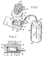
- Figure 1 is a perspective view of a humidifying device according to the present invention disposed in a position facing and at a distance from the nozzles of a machine for dispensing fluid products, and
- Figure 2 is a longitudinal section through a detail of the device of Figure 1 in the operative position of humidifying the nozzles of the dispensing machine.
- Referring now to the drawings, a machine for dispensing fluids, in particular, although not exclusively, dyes, comprises
delivery ducts 10 which open out at the ends to formdelivery nozzles 11 at the location of anozzle support 12. Ahousing 14 for aseal 15 with which afront edge wall 16 of a cup orbeaker body 17 mounted on amovable support structure 18 can be brought selectively into abutment is preferably formed in alower wall 13 of thenozzle support 12. Thesupport structure 18 is movable, by devices known to the person skilled in the art (which are not shown in the drawings) in such a manner as selectively to permit the movement of thecup body 17 towards thelower wall 13 of thenozzle support 12, in the sealed position illustrated in Figure 2, or its movement away therefrom in such a manner as to free thedelivery nozzles 11 to permit the dispensing machine operations of delivering fluid products. - A
layer 20 of material is laid on thebase 19 of thecup body 17, thelayer 20 having a high degree of capillarity and preferably being shaped in such a manner as to cover substantially the entire surface of thebase 19. Extending from one edge of thecapillary layer 20 is acapillary cord 21 which exits from thecup body 17 through ahole 22 formed in the peripheralcurved surface 23 thereof and continues inside aprotective sheath 24 until it reaches acontainer 25 for water or solvent inside which it extends as an exposedportion 26, without a sheath, until it reaches substantially thebase 27 of thecontainer 25. Preferably, thecapillary cord 21 extends through aplug 28 which closes thecontainer 25 and to which one end of thesheath 24 is secured, the other end being secured to thecup body 17, preferably by means of aconnector 29 secured to the peripheralcurved surface 23 thereof. - When the humidifying device described above is in use, the
container 25 is filled with water or solvent, acting as humidifying liquid, and is closed with theplug 28 in such a manner that the exposedportion 26 of thecapillary cord 21 is immersed in the humidifying liquid. Owing to the properties of high capillarity of the material of thecord 21, the humidifying liquid is transported to thecup body 17 until thecapillary layer 20 is completely soaked. The liquid leaving thecapillary layer 20 by evaporation is substituted by another liquid coming from thecontainer 25. - When the fluid-dispensing machine is in operation, the
cup body 17 is moved away manually or automatically from thenozzle support 12 so that the fluid to be delivered can exit from one or more of thenozzles 11 according to dispensing methods known in the sector. When the delivery operations are complete, thesupport structure 18 is moved in such a manner that the cup body reaches the humidifying position illustrated in Figure 2 in which itsfront edge wall 16 abuts thenozzle support 12, in particular at the location of theseal 15, in order to form a closed humidifying chamber inside which the ends of thedelivery ducts 10 forming thedelivery nozzles 11 are located. Owing to the presence of the moistcapillary layer 20, a humid atmosphere is created inside the humidifying chamber and impedes and prevents the drying-out of the fluid products at the location of thedelivery nozzles 11. - In the present text, the expression "cup body" is to be understood in its broadest sense and naturally covers the variants suitable for performing the functions described above with reference to the above-mentioned
cup body 17. A possible variant of the invention may provide that the moistcapillary layer 20 is brought into the vicinity of thenozzles 11, possibly as far as coming into contact therewith. - Naturally, the principle of the invention remaining the same, the forms of embodiment and the details of construction may be varied widely with respect to those described and illustrated, without thereby departing from the scope of the present invention.
Claims (8)
- A nozzle-humidifying device for a machine for dispensing fluid products, comprising movable support means (17) for means for humidifying the nozzles (11), characterised in that the humidifying means comprise capillary means having a first portion (20) which is supported by the support means (17) and a second portion (21, 26) which extends away from the support means (17) to reach reservoir means (25) for a humidifying liquid.
- A humidifying device according to claim 1, characterised in that the support means comprise a cup body (17) which, in use, is to form a closed chamber with a portion of the dispensing machine, inside which chamber the nozzles (11) to be humidified open out, the first portion (20) of the capillary means being housed in the cup body (17) and the second portion (21, 26) of the capillary means extending outside the cup body (17).
- A humidifying device according to claim 2, characterised in that the first portion (20) of the capillary means comprises a layer of capillary material laid on the base of the cup body (17).
- A humidifying device according to claim 1 or 2, characterised in that the second portion of the capillary means comprises a capillary cord (21) covered by a protective sheath (24) except for an end portion (26) housed in the reservoir means (25).
- A humidifying device according to any one of claims 2 to 4, characterised in that the second portion of the capillary means exits from the cup body (17) though a hole formed in the external curved surface thereof.
- A humidifying device according to any one of claims 2 to 5, characterised in that the cup body (17) is mounted on selectively movable support means (18).
- A dispensing machine for fluid products, comprising ducts for delivering fluid products having ends defining delivery nozzles (11) opening out in the vicinity of nozzle support means (12), characterised in that it comprises a humidifying device according to any one of the preceding claims.
- A dispensing machine according to claim 7, characterised in that it comprises sealing means (15) suitable for forming, in the operative humidifying position of the humidifying device, a chamber closed in a sealed manner.
Priority Applications (1)
| Application Number | Priority Date | Filing Date | Title |
|---|---|---|---|
| EP03425562A EP1510260A1 (en) | 2003-08-28 | 2003-08-28 | A nozzle-humidifying device for a machine for dispensing fluid products |
Applications Claiming Priority (1)
| Application Number | Priority Date | Filing Date | Title |
|---|---|---|---|
| EP03425562A EP1510260A1 (en) | 2003-08-28 | 2003-08-28 | A nozzle-humidifying device for a machine for dispensing fluid products |
Publications (1)
| Publication Number | Publication Date |
|---|---|
| EP1510260A1 true EP1510260A1 (en) | 2005-03-02 |
Family
ID=34089795
Family Applications (1)
| Application Number | Title | Priority Date | Filing Date |
|---|---|---|---|
| EP03425562A Withdrawn EP1510260A1 (en) | 2003-08-28 | 2003-08-28 | A nozzle-humidifying device for a machine for dispensing fluid products |
Country Status (1)
| Country | Link |
|---|---|
| EP (1) | EP1510260A1 (en) |
Cited By (7)
| Publication number | Priority date | Publication date | Assignee | Title |
|---|---|---|---|---|
| WO2006106102A3 (en) * | 2005-04-05 | 2007-11-15 | Cps Color Equipment Spa Con Un | Device and method for preventing the drying of fluid products in a dispensing machine for such products |
| WO2008109514A1 (en) * | 2007-03-02 | 2008-09-12 | Ultrablend, Llc | Apparatus and method for humidifying a nozzle of a colorant dispenser |
| WO2014013315A1 (en) * | 2012-07-20 | 2014-01-23 | Cps Color Equipment Spa Con Unico Socio | Device to prevent the drying of nozzles of a machine for the preparation of fluid coloring products |
| CN108355919A (en) * | 2018-05-10 | 2018-08-03 | 京东方科技集团股份有限公司 | Glue spreading apparatus and automatic glue painting device with it |
| CN112604862A (en) * | 2020-12-07 | 2021-04-06 | 南京思达捷信息科技有限公司 | Chip production equipment with crushing function |
| IT201900022872A1 (en) * | 2019-12-03 | 2021-06-03 | Dromont S P A | AUTOMATIC HUMIDIFICATION SYSTEM OF A DISPENSING HEAD OF A FLUID PRODUCT DOSING MACHINE |
| CN116510981A (en) * | 2023-05-21 | 2023-08-01 | 武汉东进包装有限公司 | Automatic dispensing machine for foam box |
Citations (2)
| Publication number | Priority date | Publication date | Assignee | Title |
|---|---|---|---|---|
| US3709110A (en) * | 1970-12-24 | 1973-01-09 | Fibreboard Corp | Apparatus and method for applying collars to container blanks |
| US4387002A (en) * | 1980-03-29 | 1983-06-07 | Maschinenfabrik Alfred Schmermund Gmbh & Co. | Adhesive discharge device |
-
2003
- 2003-08-28 EP EP03425562A patent/EP1510260A1/en not_active Withdrawn
Patent Citations (2)
| Publication number | Priority date | Publication date | Assignee | Title |
|---|---|---|---|---|
| US3709110A (en) * | 1970-12-24 | 1973-01-09 | Fibreboard Corp | Apparatus and method for applying collars to container blanks |
| US4387002A (en) * | 1980-03-29 | 1983-06-07 | Maschinenfabrik Alfred Schmermund Gmbh & Co. | Adhesive discharge device |
Cited By (16)
| Publication number | Priority date | Publication date | Assignee | Title |
|---|---|---|---|---|
| WO2006106102A3 (en) * | 2005-04-05 | 2007-11-15 | Cps Color Equipment Spa Con Un | Device and method for preventing the drying of fluid products in a dispensing machine for such products |
| JP2008538530A (en) * | 2005-04-05 | 2008-10-30 | シーピーエス・カラー・イクウィップメント・ソシエタ・ペル・アチオニ・コン・ユニコ・ソシオ | Apparatus and method for preventing drying of fluid products in a distributor for fluid products |
| CN100569392C (en) * | 2005-04-05 | 2009-12-16 | 赛皮尔斯色料设备独资有限公司 | Apparatus and method for preventing fluid product from drying out in a fluid product dispensing machine |
| US7905240B2 (en) | 2005-04-05 | 2011-03-15 | Cps Color Equipment Spa Con Unico Socio | Device and method for preventing the drying of fluid products in a dispensing machine for such products |
| WO2008109514A1 (en) * | 2007-03-02 | 2008-09-12 | Ultrablend, Llc | Apparatus and method for humidifying a nozzle of a colorant dispenser |
| US9925551B2 (en) | 2012-07-20 | 2018-03-27 | Corob S.P.A. Con Socio Unico | Device to prevent the drying of nozzles of a machine for the preparation of fluid coloring products |
| WO2014013315A1 (en) * | 2012-07-20 | 2014-01-23 | Cps Color Equipment Spa Con Unico Socio | Device to prevent the drying of nozzles of a machine for the preparation of fluid coloring products |
| CN108355919A (en) * | 2018-05-10 | 2018-08-03 | 京东方科技集团股份有限公司 | Glue spreading apparatus and automatic glue painting device with it |
| US11951503B2 (en) | 2019-12-03 | 2024-04-09 | Dromont S.P.A. | Automatic humidification system for a dispensing head of a dosing machine of fluid products |
| IT201900022872A1 (en) * | 2019-12-03 | 2021-06-03 | Dromont S P A | AUTOMATIC HUMIDIFICATION SYSTEM OF A DISPENSING HEAD OF A FLUID PRODUCT DOSING MACHINE |
| CN112899913A (en) * | 2019-12-03 | 2021-06-04 | 德罗蒙特股份公司 | Automatic humidification system for a dispensing head of a dosing machine for fluid products |
| EP3838430A1 (en) * | 2019-12-03 | 2021-06-23 | Dromont S.p.A. | An automatic humidification system for a dispensing head of a dosing machine of fluid products |
| CN112899913B (en) * | 2019-12-03 | 2024-12-13 | 德罗蒙特股份公司 | Automatic humidification system for the dispensing heads of dosing machines for fluid products |
| CN112604862A (en) * | 2020-12-07 | 2021-04-06 | 南京思达捷信息科技有限公司 | Chip production equipment with crushing function |
| CN116510981B (en) * | 2023-05-21 | 2023-11-03 | 武汉东进包装有限公司 | Automatic dispensing machine for foam box |
| CN116510981A (en) * | 2023-05-21 | 2023-08-01 | 武汉东进包装有限公司 | Automatic dispensing machine for foam box |
Similar Documents
| Publication | Publication Date | Title |
|---|---|---|
| US9360227B2 (en) | Removable top fill tank | |
| US5483616A (en) | Humidifier tank with improved handle | |
| US8272140B2 (en) | Fluid reservoir assembly | |
| US8523020B2 (en) | Vented dispensing device | |
| KR20000071692A (en) | Cleansing and freshening unit intended for suspension from a rim of a toilet bowl | |
| CN101133203A (en) | Apparatus including additive containers for ironing or smoothing laundry | |
| WO2007142851A3 (en) | Passive dispensing device | |
| JP5370290B2 (en) | Small humidifier and small humidifier equipped with electrostatic atomization means | |
| KR20110056547A (en) | Natural evaporative humidifier | |
| US7004660B2 (en) | Closure cap with refilling function | |
| JP5747156B2 (en) | Humidifier | |
| KR101381948B1 (en) | Humidifier | |
| US5682932A (en) | Humidifier water bottle | |
| EP1172220A3 (en) | Ink catridge | |
| US7824120B1 (en) | Hand held carpet spot cleaner | |
| KR101375858B1 (en) | Erase for water boards | |
| MXPA01007116A (en) | Ink cartridge with overflow conduit. | |
| JP5412854B2 (en) | humidifier | |
| CN208615597U (en) | A kind of anti-drying inkstone device | |
| US6315272B1 (en) | Humidifier with stacked reservoir | |
| JP3653851B2 (en) | Water soap dispenser | |
| CN112899913B (en) | Automatic humidification system for the dispensing heads of dosing machines for fluid products | |
| ES2283426T3 (en) | APPARATUS TO AVOID DRYING A NOZZLE OF A FLUID DISPENSING DEVICE. | |
| AU769422B2 (en) | Receptacle for the diffusion of a fragrant liquid | |
| JP4648256B2 (en) | Water supply equipment |
Legal Events
| Date | Code | Title | Description |
|---|---|---|---|
| PUAI | Public reference made under article 153(3) epc to a published international application that has entered the european phase |
Free format text: ORIGINAL CODE: 0009012 |
|
| AK | Designated contracting states |
Kind code of ref document: A1 Designated state(s): AT BE BG CH CY CZ DE DK EE ES FI FR GB GR HU IE IT LI LU MC NL PT RO SE SI SK TR |
|
| AX | Request for extension of the european patent |
Extension state: AL LT LV MK |
|
| AKX | Designation fees paid | ||
| REG | Reference to a national code |
Ref country code: DE Ref legal event code: 8566 |
|
| STAA | Information on the status of an ep patent application or granted ep patent |
Free format text: STATUS: THE APPLICATION IS DEEMED TO BE WITHDRAWN |
|
| 18D | Application deemed to be withdrawn |
Effective date: 20050903 |