EP1868320B1 - Verwaltungssystem und Verfahren für ein drahtloses Kommunikationsnetz und zugehörige grafische Benutzerschnittstelle - Google Patents
Verwaltungssystem und Verfahren für ein drahtloses Kommunikationsnetz und zugehörige grafische Benutzerschnittstelle Download PDFInfo
- Publication number
- EP1868320B1 EP1868320B1 EP07252426A EP07252426A EP1868320B1 EP 1868320 B1 EP1868320 B1 EP 1868320B1 EP 07252426 A EP07252426 A EP 07252426A EP 07252426 A EP07252426 A EP 07252426A EP 1868320 B1 EP1868320 B1 EP 1868320B1
- Authority
- EP
- European Patent Office
- Prior art keywords
- forecast
- network
- value
- effect ratio
- operation index
- Prior art date
- Legal status (The legal status is an assumption and is not a legal conclusion. Google has not performed a legal analysis and makes no representation as to the accuracy of the status listed.)
- Active
Links
Images


Classifications
-
- H—ELECTRICITY
- H04—ELECTRIC COMMUNICATION TECHNIQUE
- H04L—TRANSMISSION OF DIGITAL INFORMATION, e.g. TELEGRAPHIC COMMUNICATION
- H04L41/00—Arrangements for maintenance, administration or management of data switching networks, e.g. of packet switching networks
- H04L41/22—Arrangements for maintenance, administration or management of data switching networks, e.g. of packet switching networks comprising specially adapted graphical user interfaces [GUI]
-
- H—ELECTRICITY
- H04—ELECTRIC COMMUNICATION TECHNIQUE
- H04L—TRANSMISSION OF DIGITAL INFORMATION, e.g. TELEGRAPHIC COMMUNICATION
- H04L43/00—Arrangements for monitoring or testing data switching networks
-
- H—ELECTRICITY
- H04—ELECTRIC COMMUNICATION TECHNIQUE
- H04W—WIRELESS COMMUNICATION NETWORKS
- H04W24/00—Supervisory, monitoring or testing arrangements
-
- H—ELECTRICITY
- H04—ELECTRIC COMMUNICATION TECHNIQUE
- H04L—TRANSMISSION OF DIGITAL INFORMATION, e.g. TELEGRAPHIC COMMUNICATION
- H04L41/00—Arrangements for maintenance, administration or management of data switching networks, e.g. of packet switching networks
- H04L41/14—Network analysis or design
- H04L41/149—Network analysis or design for prediction of maintenance
-
- H—ELECTRICITY
- H04—ELECTRIC COMMUNICATION TECHNIQUE
- H04L—TRANSMISSION OF DIGITAL INFORMATION, e.g. TELEGRAPHIC COMMUNICATION
- H04L43/00—Arrangements for monitoring or testing data switching networks
- H04L43/08—Monitoring or testing based on specific metrics, e.g. QoS, energy consumption or environmental parameters
- H04L43/0805—Monitoring or testing based on specific metrics, e.g. QoS, energy consumption or environmental parameters by checking availability
- H04L43/0817—Monitoring or testing based on specific metrics, e.g. QoS, energy consumption or environmental parameters by checking availability by checking functioning
-
- H—ELECTRICITY
- H04—ELECTRIC COMMUNICATION TECHNIQUE
- H04L—TRANSMISSION OF DIGITAL INFORMATION, e.g. TELEGRAPHIC COMMUNICATION
- H04L43/00—Arrangements for monitoring or testing data switching networks
- H04L43/16—Threshold monitoring
-
- H—ELECTRICITY
- H04—ELECTRIC COMMUNICATION TECHNIQUE
- H04L—TRANSMISSION OF DIGITAL INFORMATION, e.g. TELEGRAPHIC COMMUNICATION
- H04L67/00—Network arrangements or protocols for supporting network services or applications
- H04L67/01—Protocols
- H04L67/04—Protocols specially adapted for terminals or networks with limited capabilities; specially adapted for terminal portability
-
- H—ELECTRICITY
- H04—ELECTRIC COMMUNICATION TECHNIQUE
- H04W—WIRELESS COMMUNICATION NETWORKS
- H04W24/00—Supervisory, monitoring or testing arrangements
- H04W24/08—Testing, supervising or monitoring using real traffic
Definitions
- the present invention relates to a wireless communications network, and more particularly, to a management system and method for the wireless communications network and an associated graphic user interface.
- a wireless communications network such as a mobile network
- the prior art does not provide an efficient and convenient tool for the telecom user to make prediction and perform network diagnosis.
- the prior art predicts the future operation status of the network component by the time series prediction technique, which often lacks accuracy since only history data of the network component itself is considered.
- WO 2006/015441 defines a method and apparatus for managing a network by comparing measured performance values with expected performance values and alerts when a degradation is detected
- US 2005/097161 defines a system and method for network planning via a time series prediction mechanism that predicts future mobility and future traffic values.
- an aim of the present invention to provide a management system and method for a wireless communications network which provides an efficient and convenient graphic user interface for displaying the future operation status of network components, thereby facilitating the telecom user to perform network diagnosis and network adjustment for remedy.
- Another aim of the present invention is to provide a management system and method for a wireless communications network which provides more accurate prediction by considering the influence from the parent, son, and neighbour components of a network component.
- the present invention provides a management system for a wireless communications network, the system comprising: a forecast module for generating a forecast value for a first operation index of at least a first network component of the wireless communications network during at least a forecast period; and a display module, connected to the forecast module, for providing a graphic user interface which comprises a forecast table to show the forecast value; wherein the forecast module determines whether to enable a warning function of the graphic user interface according to a comparison of the forecast value and a warning value; characterised in that: the forecast module generates the forecase value according to an initial prediction value and a total effect ratio, the forecast module generating the initial prediction value by a time series prediction technique, and generating the total effect ratio according to a parent effect ratio, a son effect ratio and a neighbour effect ratio; and in that the parent effect ratio is determined according to a variation of the first operation index of each parent network component of the first network component, the son effect ratio is determined according to a variation of the first operation index of each son network component of the first network component, and the
- GSM Global System for Mobile communication
- GSM Global System for Mobile communication
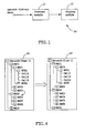
- Fig. is a block diagram of a preferred embodiment of a management system for a wireless communication network according to the present invention.
- the wireless communication network includes a plurality of network components deployed as a multi-level structure.
- a GSM network may contain, from top to bottom, a network level (the GSM network itself), a MSC (i.e. mobile switching center) level, a BSC (i.e. base station controller) level, a BTS (i.e. base transceiver station) level and a cell level.
- the management system 10 includes a forecast module 11 and a display module 12.
- the forecast module 11 According to received network history data, the forecast module 11 generates a forecast value for each available operation index of the network components of the wireless communication network during a plurality of forecast periods.
- the network history data record network traffic status or network user behavior during past periods, and are provided by various sources, such as an operation and maintenance center (OMC) or operation support system (OSS), a database, or an optical disk.
- OMC operation and maintenance center
- OSS operation support system
- the OMC usually provides real-time or short-term statistic data, while long-term statistic data are stored in the database and the optical disk.
- an operation index of a network component reflects a specific network traffic status or network user behavior involving the network component, and history values of the operation index can be retrieved or derived from the network history data.
- the types of the operation index are various, for example, the operation index of a MSC includes Erlang, port, BHCA (i.e. busy hour call attempt), CPU loading, etc. These examples of the operation index are well known to people skilled in the art and will not be described in detail here. Besides, the operation index may be directly used as a network performance index, such as a key performance index (KPI).
- KPI key performance index
- the display module 12 is connected to the forecast module 11, and provides a graphic user interface 20 for a telecom user or network administrator to manage the wireless communication network.
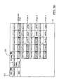
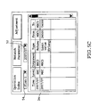
- Fig.2 is a diagram showing an embodiment of the graphic user interface 20, where the graphic user interface 20 includes a forecast table 21, a network tree graph 22, a map 23, and a function window 24.
- the forecast table 21 shows a forecast value for a certain operation index (selected by an index-selecting field 211) of each network component of a certain level (selected by a level-selecting field 212) of the wireless communication network during a plurality of forecast periods.
- the graphic user interface 20 in Fig.2 takes a GSM network as example, and the forecast table 21 shows the forecast values for the operation index "Erlang" of the network components (i.e. MSC1 ⁇ MSC3) of the MSC level during June of 2007 to October of 2007. It is notable that the forecast table 21 can also show the forecast values for more forecast periods and the history values for past periods, thereby facilitating the telecom user to observe the
- the forecast module 11 determines whether to enable a warning function of the graphic user interface 20 according to a comparison of the forecast value and a warning value for the operation index of the network component. If the forecast value exceeds the warning value, it means the network component is under an overloaded state and needs an adjustment for remedy. It is notable that the warning value for the same operation index of different network components can be different.
- the warning function warns the telecom user by using a distinct color (e.g. red) to show the forecast value that exceeds the warning value.
- Fig.2 the forecast values for Erlang of MSC2 during August to October of 2007 exceed the warning value, and are shown in the distinct color (represented by oblique lines in Fig.2 ). It is notable that more than one warning value can be used to indicate various warning degrees, and the warning function can use different colors to show the forecast values for differentiation.
- the graphic user interface 20 further includes a plan-selecting field 25 for selecting an original or adjusted network plan of the wireless communication network to show the forecast value of the operation index thereunder.
- a network plan means how the components of a network are organized or connected.
- various types of adjustments (will be further described below) can be made on the original network plan to generate an adjusted network plan.
- the forecast table 21 can then show the forecast values of the operation index under different network plans for comparison. For example, the telecom user can take June to October of 2007 as a planning period to generate three different adjusted plans by performing different (or different sets of) adjustments during different forecast periods, as shown in Fig.3A .
- Fig.3A Plan-1 is generated by making Adjustment A in 2007/06 and Adjustment B in 2007/08
- Plan-2 is generated by making Adjustment A in 2007/06 and Adjustment C in 2007/09
- Plan-3 is generated by making Adjustment A in 2007/06, Adjustment B in 2007/08 and Adjustment D in 2007/09.
- Fig.3B the time series of the forecast values of the operation index (Erlang as shown) under the original and adjusted plans during 2007/06-2007/10 are shown in the forecast table 21 for convenient comparison.
- a" 0 "symbol (other identifiable symbol can also be used) in front of a forecast period means that there is an adjustment made during this period.
- the network tree graph 22 displays a tree structure of the network components of the wireless communication network.
- the tree structure is inherent in the multi-level structure of the network, and an upper-level (or parent) component manages at least one lower-level (or son) component.
- the network tree graph 22 shows a five-level (i.e. network level, MSC level, BSC level, BTS level and cell level) tree structure of Plan-1 of the GSM network.
- the "+" symbol in front of a network component means there are hidden lower-level components under it, and the "-" symbol means the hidden lower-level components are explicitly shown.
- the tree structure can be easily adjusted. For example, by using a pointing device (e.g. mouse), BSC3 can be easily moved (rehomed) from MSC 1 to MSC2, as shown by Fig.4 .
- a pointing device e.g. mouse
- the map 23 shows where the network components of the wireless communication network are located.
- the network components can be shown in a visualized manner for convenient observation.
- the components of different levels can be shown in different shapes, such as circles (i.e. BTS in Fig.2 ), triangles (i.e. BSC in Fig.2 ), rectangles (i.e. MSC in Fig.2 ), etc.
- the son components belonging to the same parent component can be shown in the same color.
- the content of the forecast table 21, the network tree graph 22, and the map 23 can be updated and shown synchronously. That is, if a forecast period in the forecast table 21 is selected (e.g. by using a point device to click any of the columns 2007/06-2007/10 in Fig.2 ), the network tree graph 22 will show the corresponding tree structure during the selected forecast period, and the map 23 will show where the network components are located during the selected forecast period.
- the telecom user can easily perform a network diagnosis by observing the status of parent and son components and neighboring components of some problematic component.
- the telecom user can observe whether the specific MSC contains too many BSCs through the network tree graph 22 or observe the distribution of the BSCs of the specific MSC through the map 23 to find out the problem cause.
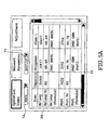
- the function window 24 provides several functions to facilitate the telecom user to manage the wireless communication network. As shown in Fig.2 , the function window 24 includes three function tabs: Operation Index, Network Parameter and Adjustment, and the content of these tabs are shown in Fig.5A-5C .
- Fig.5A shows the content of the Operation Index tab, which includes a component-selecting field 51 for selecting a network component and a period-selecting field 52 for selecting a forecast period.
- the other content of the Operation Index tab are arranged into a plurality of columns for showing related information for each available operation index of the selected component during the selected forecast period.
- the column "Item" includes the name, percentage and formula for each available operation index.
- the limit value of Erlang of MSC 1 is 24000 and the warning percentage of Erlang of MSC 1 is 80 during 2007/07.
- the fields corresponding to the items of name, percentage and formula are respectively the forecast value, the percentage of the forecast value to the limit value and the formula used for calculating the forecast value under the respective plan.
- the formula is determined according to at least an operation index and at least a network parameter, such as mathematical operations on the operation index and network parameter.
- the forecast value of Erlang of MSC1 is 16437 and the percentage of the forecast value to the limit value under the original plan is 68.49 during 2007/07;
- the formula for calculating the forecast value of Erlang of MSC1 is "[MSC BHCA] * [MSC BHCA To VLR Sub Ratio]" (the full expression of the formula can be shown by using a pointing device to click the corresponding field), where "MSC BHCA” is another operation index and MSC BHCA To VLR Sub Ratio is a network parameter.
- the warning value for an operation index can be adjusted by directly changing the field of the "Capacity” column for recording the limit value or the warning percentage of the operation index.
- the formula for calculating the forecast value of an operation index can also be adjusted by directly changing the fields of the Original, Plan-1, Plan-2 or Plan-3 column for recording the formula.
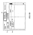
- Fig.5B shows the content of the Network Parameter tab, which also includes the component-selecting field 51 and the period-selecting field 52.
- the other content of the Network Parameter tab are arranged into "Parameter” and "Value" columns for recording the setting value for each network parameter included in the formulas for calculating the forecast values for the operation indexes of the selected component during the selected forecast period.
- the setting value of MSC BHCA To VLR Sub Ratio which is included in the formula for calculating the forecast value of Erlang of MSC 1 during 2007/07, is 1.5.
- the setting value of a network parameter can be adjusted by directly changing the field of the "Value" column for recording the setting value of the network parameter.
- Fig.5C shows the content of the Adjustment tab, which includes the period-selecting field 52 and a plan-selecting field 54 for selecting the original plan or an adjusted plan.
- the other content of the Adjustment tab are arranged into the columns of "Time”, “Level”, “Component”, “Type”, “From (former state)” and “To (target state)” for recording related information of each adjustment performed not later than the selected forecast period under the selected plan.
- the types of the adjustment include:
- the prediction module After an adjustment is performed, its related information will be recorded in the Adjustment tab of the function window 24. If the performed adjustment influences a forecast value or the warning state of a forecast value thereafter, the prediction module will update the influenced forecast value or warning state according to the performed adjustment and show the updated result in the graphic user interface 20.
- the forecast module 11 is a computer running a forecast software
- the display module 12 is a CRT or LDC monitor.
- the graphic user interface 20 is a window interface of an operating system.
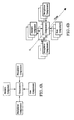
- the forecast module 11 When generating a forecast value for an operation index of a certain network component, the forecast module 11 not only uses the time series of history values, but also considers the influence from the parent, son, and neighbor components of the certain component, as shown in Fig.6A . Further, the generated forecast values can be used as part of the time series data to generate the next forecast value, as shown in Fig.6B , such that the forecast values with more accuracy can be generated.
- the influence from the parent, son and neighbor components can be respectively modeled as a parent effect ratio, a son effect ratio and a neighbor effect ratio.
- the parent effect ratio can be determined according to the variation of the operation index of the parent component.
- the variation of the operation index of its parent component i.e. the whole network
- the estimated growth rate can be generated according to marketing effect, the growth/decline of new/old technology (e.g. 3G/2G network), etc.
- the variation of the operation index of the whole network e.g. 10%
- a distribution percentage which can be determined according to, for example, the average ratio of the operation index of MSC1 to that of the whole network during past periods.
- the parent effect ratio of MSC1 can be determined from the variation of the operation index of the whole network and the distribution percentage.
- the parent effect ratio of a BSC or a BTS can also be determined in the manner similar to above.
- the neighbor effect ratio can be determined according to the variation of the operation index of the neighbor component. For instance, if some neighbor MSC of MSC is over-loaded, then a portion of traffic of the neighbor MSC will be re-assigned to MSC 1 (reflected in the variation of the operation index of the neighbor MSC); a newly added neighbor MSC will share some loading of MSC1 (reflected in the variation of the operation index of the new MSC). Then, the neighbor effect ratio of MSC1 can be determined from the factors as described above. The neighbor effect ratio of a BSC or a BTS can also be determined in the similar manner.
- Fig.7 is a flow chart of a preferred embodiment of the management method for a wireless communication network according to the present invention.
- the flow in Fig.7 comprises steps of:
Landscapes
- Engineering & Computer Science (AREA)
- Computer Networks & Wireless Communication (AREA)
- Signal Processing (AREA)
- Human Computer Interaction (AREA)
- Mobile Radio Communication Systems (AREA)
- Telephonic Communication Services (AREA)
Claims (11)
- Verwaltungssystem für ein drahtloses Kommunikationsnetzwerk, wobei das System enthält:ein Vorhersagemodul (11) zur Erzeugung eines Vorhersagewerts für einen ersten Operationsindex wenigstens einer ersten Netzwerkkomponente des drahtlosen Kommunikationsnetzwerks während wenigstens einer Vorhersageperiode undein an das Vorhersagemodul angeschlossenes Anzeigemodul (12) zur Bereitstellung einer graphischen Nutzerschnittstelle (20), die eine Vorhersagetabelle (21) zum Anzeigen des ersten Vorhersagewerts enthält,wobei das Vorhersagemodul gemäß Vergleich des Vorhersagewerts mit einem Warnwert bestimmt, ob eine Warnfunktion der graphischen Nutzerschnittstelle aktiviert wird,dadurch gekennzeichnet, dass:das Vorhersagemodul den Vorhersagewert gemäß einem Anfangsprognosewert und einem Gesamtwirkverhältnis erzeugt, wobei das Vorhersagemodul den Anfangsprognosewert durch eine Zeitfolgeprognosetechnik erzeugt und das Gesamtwirkverhältnis gemäß einem Elternwirkverhältnis, einem Sohnwirkverhältnis und einem Nachbarwirkverhältnis erzeugt,und dadurch, dass das Elternwirkverhältnis gemäß einer Änderung eines ersten Operationsindex einer jeden Elternnetzwerkkomponente der ersten Netzwerkkomponente bestimmt wird, das Sohnwirkverhältnis gemäß einer Änderung eines ersten Operationsindex einer jeden Sohnnetzwerkkomponente der ersten Netzwerkkomponente bestimmt wird und das Nachbarwirkverhältnis gemäß einer Änderung eines ersten Operationsindex einer jeden Nachbarnetzwerkkomponente der ersten Netzwerkkomponente bestimmt wird.
- Verwaltungssystem nach Anspruch 1, bei dem die Vorhersagetabelle (21) ein Levelauswahlfeld (212) zur Auswahl eines aus einer Vielzahl von Levels des drahtlosen Kommunikationsnetzwerks enthält, wobei die Vorhersagetabelle Vorhersagewerte für den ersten Operationsindex einer Vielzahl von Netzwerkkomponenten des ausgewählten Levels während wenigstens der einen Vorhersageperiode zeigt.
- Verwaltungssystem nach Anspruch 2, bei dem die graphische Nutzerschnittstelle (20) darüber hinaus einen Netzwerkbaumgraphen (22) zur Anzeige einer Baumstruktur der Netzwerkkomponenten der Levels enthält und eine Einstellung der Baumstruktur mittels des Netzwerkbaumgraphen ausgeführt wird.
- Verwaltungssystem nach einem der Ansprüche 1 bis 3, bei dem die graphische Nutzerschnittstelle (20) darüber hinaus eine Karte (23) enthält, um anzuzeigen, wo sich eine Vielzahl von Netzwerkkomponenten des drahtlosen Kommunikationsnetzwerks befindet.
- Verwaltungssystem nach einem der Ansprüche 1 bis 4, bei dem die graphische Nutzerschnittstelle (20) darüber hinaus ein Funktionsfenster (24) zur Anzeige des Wamwerts enthält und der Warnwert mittels des Funktionsfensters eingestellt wird.
- Verwaltungssystem nach Anspruch 5, bei dem das Funktionsfenster (24) darüber hinaus eine Formel zur Berechnung des Wamwerts zeigt und die Formel mittels des Funktionsfensters eingestellt wird.
- Verwaltungssystem nach Anspruch 5 oder Anspruch 6, bei dem eine Einstellung für das drahtlose Kommunikationssystem mittels der graphischen Nutzerschnittstelle (20) ausgeführt wird, wobei die Einstellung eine des folgenden Typs ist: Rückkehreinstellung, Wamwerteinstellung, Formeleinstellung und Parametereinstellung.
- Verwaltungssystem nach Anspruch 7, bei dem der Vorhersagewert und der Warnwert gemäß der Einstellung selektiv aktualisiert werden.
- Verwaltungssystem nach Anspruch 7 oder Anspruch 8, bei dem das Funktionsfenster (24) eine zugehörige Information der Einstellung aufzeichnet, wobei die zugehörige Einstellung wenigstens eine der folgenden enthält: Ausführungszeit, Ausführungslevel, ausgeführte Netzwerkkomponente, Einstelltyp, vorheriger Zustand und Zielzustand.
- Verwaltungssystem nach einem der Ansprüche 7 bis 9, bei dem die Vorhersagetabelle (21) einen ersten Vorhersagewert und einen zweiten Vorhersagewert für den ersten Operationsindex der ersten Netzwerkkomponente während der Vorhersageperiode zeigt, wobei der erste Vorhersagewert und der zweite Vorhersagewert jeweils einem ersten Satz von Einstellungen und einem zweiten Satz von Einstellungen entsprechen, von denen beide nicht später als die Vorhersageperiode sind.
- Verwaltungsverfahren für ein drahtloses Kommunikationsnetzwerk, wobei das Verfahren umfasst:Erzeugen eines Vorhersagewerts für einen ersten Operationsindex wenigstens einer ersten Netzwerkkomponente des drahtlosen Kommunikationsnetzwerks während wenigstens einer Vorhersageperiode,Bereitstellen einer graphischen Nutzerschnittstelle (20), die eine Vorhersagetabelle (21) zum Anzeigen des ersten Vorhersagewerts enthält,Anzeigen einer Baumstruktur einer Vielzahl von Netzwerkkomponenten des drahtlosen Kommunikationsnetzwerks durch einen Netzwerkbaumgraphen (22) der graphischen Nutzerschnittstelle,Anzeigen durch eine Karte (23) der graphischen Nutzerschnittstelle, wo sich die Netzwerkkomponenten befinden,Bestimmen gemäß Vergleich des Vorhersagewerts mit einem Wamwert, ob eine Warnfunktion der graphischen Nutzerschnittstelle aktiviert wird,dadurch gekennzeichnet, dass:der Vorhersagewert gemäß einem Anfangsprognosewert und einem Gesamtwirkverhältnis erzeugt wird, wobei der Anfangsprognosewert durch eine Zeitfolgeprognosetechnik erzeugt wird und das Gesamtwirkverhältnis gemäß einem Elternwirkverhältnis, einem Sohnwirkverhältnis und einem Nachbarwirkverhältnis erzeugt wird,und dadurch, dass das Elternwirkverhältnis gemäß einer Änderung eines Operationsindex einer jeden Eltemnetzwerkkomponente der wenigstens ersten Netzwerkkomponente bestimmt wird, das Sohnwirkverhältnis gemäß einer Änderung eines Operationsindex einer jeden Sohnnetzwerkkomponente der wenigstens ersten Netzwerkkomponente bestimmt wird und das Nachbarwirkverhältnis gemäß einer Änderung eines Operationsindex einer jeden Nachbametzwerkkomponente der wenigstens ersten Netzwerkkomponente bestimmt wird.
Applications Claiming Priority (1)
| Application Number | Priority Date | Filing Date | Title |
|---|---|---|---|
| US81393206P | 2006-06-16 | 2006-06-16 |
Publications (3)
| Publication Number | Publication Date |
|---|---|
| EP1868320A2 EP1868320A2 (de) | 2007-12-19 |
| EP1868320A3 EP1868320A3 (de) | 2008-08-27 |
| EP1868320B1 true EP1868320B1 (de) | 2010-08-11 |
Family
ID=38531734
Family Applications (1)
| Application Number | Title | Priority Date | Filing Date |
|---|---|---|---|
| EP07252426A Active EP1868320B1 (de) | 2006-06-16 | 2007-06-14 | Verwaltungssystem und Verfahren für ein drahtloses Kommunikationsnetz und zugehörige grafische Benutzerschnittstelle |
Country Status (4)
| Country | Link |
|---|---|
| US (1) | US8549406B2 (de) |
| EP (1) | EP1868320B1 (de) |
| AT (1) | ATE477642T1 (de) |
| DE (1) | DE602007008322D1 (de) |
Families Citing this family (17)
| Publication number | Priority date | Publication date | Assignee | Title |
|---|---|---|---|---|
| US7561876B2 (en) * | 2003-02-21 | 2009-07-14 | Groundhog Technologies Inc. | System with user interface for network planning and mobility management optimization in a mobile communication network and method thereof |
| EP1702301A4 (de) * | 2004-01-06 | 2014-01-01 | Cerion Optimization Services Inc | System und verfahren zum analysieren strategischer netzwerkinvestitionen in drahtlosen netzwerken |
| US7929459B2 (en) * | 2004-10-19 | 2011-04-19 | At&T Mobility Ii Llc | Method and apparatus for automatically determining the manner in which to allocate available capital to achieve a desired level of network quality performance |
| US8073720B2 (en) * | 2006-04-18 | 2011-12-06 | Cerlon Optimization Services, Inc. | System and method for reduction of cost of ownership for wireless communication networks |
| EP1868320B1 (de) | 2006-06-16 | 2010-08-11 | Groundhog Technologies Inc. | Verwaltungssystem und Verfahren für ein drahtloses Kommunikationsnetz und zugehörige grafische Benutzerschnittstelle |
| EP2082537B1 (de) * | 2006-10-02 | 2013-11-20 | Cerion Optimization Services, Inc. | System und verfahren zur re-home-sequenzierungsoptimierung |
| US9659063B2 (en) * | 2010-12-17 | 2017-05-23 | Software Ag | Systems and/or methods for event stream deviation detection |
| WO2013058764A1 (en) * | 2011-10-21 | 2013-04-25 | Iomnis Surveillance Solution | Network design system |
| US8886576B1 (en) | 2012-06-22 | 2014-11-11 | Google Inc. | Automatic label suggestions for albums based on machine learning |
| EP2750432A1 (de) * | 2012-12-28 | 2014-07-02 | Telefónica, S.A. | Verfahren und System zur Vorhersage der Kanalverwendung |
| US9439081B1 (en) * | 2013-02-04 | 2016-09-06 | Further LLC | Systems and methods for network performance forecasting |
| EP2934037B1 (de) * | 2014-04-15 | 2016-04-13 | Telefonaktiebolaget LM Ericsson (publ) | Technik zur Auswertung einer Parametereinstellung in einem mobilen Kommunikationsnetz |
| US10200877B1 (en) * | 2015-05-14 | 2019-02-05 | Roger Ray Skidmore | Systems and methods for telecommunications network design, improvement, expansion, and deployment |
| US9792259B2 (en) | 2015-12-17 | 2017-10-17 | Software Ag | Systems and/or methods for interactive exploration of dependencies in streaming data |
| US10367697B2 (en) * | 2017-04-28 | 2019-07-30 | Cisco Technology, Inc. | Graphical timeline display of network client connections with wireless endpoints |
| TWI776287B (zh) * | 2020-11-24 | 2022-09-01 | 威聯通科技股份有限公司 | 雲端檔案存取裝置及方法 |
| CN116668322A (zh) * | 2022-02-28 | 2023-08-29 | 瞻博网络公司 | 用于5g网络切片供应的用户界面 |
Family Cites Families (12)
| Publication number | Priority date | Publication date | Assignee | Title |
|---|---|---|---|---|
| JP3159979B2 (ja) * | 1990-05-01 | 2001-04-23 | 株式会社日立製作所 | 網管理表示処理システム及び方法 |
| EP0807348B1 (de) * | 1995-02-02 | 2000-03-22 | Cabletron Systems, Inc. | Verfahren und anordnung zum lernen von verhaltentrends von netzwerken und vorhersagen des zukünftigen verhaltens von datenübertagungsnetzwerken |
| US6456306B1 (en) * | 1995-06-08 | 2002-09-24 | Nortel Networks Limited | Method and apparatus for displaying health status of network devices |
| DE19746904B4 (de) * | 1997-10-23 | 2004-09-30 | Telefonaktiebolaget L M Ericsson (Publ) | Verkehrsdaten-Bewertungsgerät und zugeordnetes Verfahren für ein Netzwerk mit dynamischer Vermittlung |
| US6590587B1 (en) * | 1999-11-30 | 2003-07-08 | Agilent Technologies, Inc. | Monitoring system and method implementing navigation interface logic |
| US20040136379A1 (en) * | 2001-03-13 | 2004-07-15 | Liao Raymond R | Method and apparatus for allocation of resources |
| US7093010B2 (en) * | 2002-05-20 | 2006-08-15 | Telefonaktiebolaget Lm Ericsson (Publ) | Operator-defined consistency checking in a network management system |
| US7561876B2 (en) * | 2003-02-21 | 2009-07-14 | Groundhog Technologies Inc. | System with user interface for network planning and mobility management optimization in a mobile communication network and method thereof |
| GB2434670B (en) * | 2004-08-13 | 2008-06-11 | Remasys Pty Ltd | Monitoring and management of distributed information systems |
| JP4673727B2 (ja) * | 2005-11-21 | 2011-04-20 | 株式会社リコー | 需要予測方法及び需要予測プログラム |
| US20070192065A1 (en) * | 2006-02-14 | 2007-08-16 | Sun Microsystems, Inc. | Embedded performance forecasting of network devices |
| EP1868320B1 (de) | 2006-06-16 | 2010-08-11 | Groundhog Technologies Inc. | Verwaltungssystem und Verfahren für ein drahtloses Kommunikationsnetz und zugehörige grafische Benutzerschnittstelle |
-
2007
- 2007-06-14 EP EP07252426A patent/EP1868320B1/de active Active
- 2007-06-14 DE DE602007008322T patent/DE602007008322D1/de active Active
- 2007-06-14 AT AT07252426T patent/ATE477642T1/de not_active IP Right Cessation
- 2007-06-15 US US11/812,248 patent/US8549406B2/en active Active
Also Published As
| Publication number | Publication date |
|---|---|
| US20080109731A1 (en) | 2008-05-08 |
| EP1868320A3 (de) | 2008-08-27 |
| ATE477642T1 (de) | 2010-08-15 |
| DE602007008322D1 (de) | 2010-09-23 |
| EP1868320A2 (de) | 2007-12-19 |
| US8549406B2 (en) | 2013-10-01 |
Similar Documents
| Publication | Publication Date | Title |
|---|---|---|
| EP1868320B1 (de) | Verwaltungssystem und Verfahren für ein drahtloses Kommunikationsnetz und zugehörige grafische Benutzerschnittstelle | |
| US7561876B2 (en) | System with user interface for network planning and mobility management optimization in a mobile communication network and method thereof | |
| US6356758B1 (en) | Wireless tools for data manipulation and visualization | |
| US7295119B2 (en) | System and method for indicating the presence or physical location of persons or devices in a site specific representation of a physical environment | |
| EP2082537B1 (de) | System und verfahren zur re-home-sequenzierungsoptimierung | |
| US6336035B1 (en) | Tools for wireless network planning | |
| US8185124B2 (en) | Base station system performance measurement system in a GSM radio communication network | |
| US7295960B2 (en) | System and method for automated placement or configuration of equipment for obtaining desired network performance objectives | |
| US9154977B2 (en) | Mobile phone network management systems | |
| CN101296477B (zh) | 一种进行网络拓扑规划的方法及装置 | |
| US20140052850A1 (en) | Datacenter Capacity Planning and Management | |
| AU5443796A (en) | Method and apparatus for displaying information in a communication system | |
| US7747254B2 (en) | Management system and method for wireless communication network and associated user interface | |
| EP1398975A1 (de) | Methode zur Instandhaltung eines Funknetzwerkes mit Elementen von mehr als einem Lieferanten und Komponeneten dafür | |
| US20260012401A1 (en) | System and method for visualizing key metrics of wireless nodes | |
| EP1881642A1 (de) | Überwachung von Netzinformationen | |
| US20260012820A1 (en) | System and method for determining an operative status of a base grid for network analysis | |
| Mende et al. | Mobile radio network management supported by a planning tool | |
| WO2025004091A1 (en) | System and method for real-time network view using sites and coverage view | |
| WO2025203080A1 (en) | System and method for adjusting antenna azimuth angles at network sites | |
| US7107181B2 (en) | Methods, systems, and storage mediums for maintaining timing supplies and assignments |
Legal Events
| Date | Code | Title | Description |
|---|---|---|---|
| PUAI | Public reference made under article 153(3) epc to a published international application that has entered the european phase |
Free format text: ORIGINAL CODE: 0009012 |
|
| 17P | Request for examination filed |
Effective date: 20070629 |
|
| AK | Designated contracting states |
Kind code of ref document: A2 Designated state(s): AT BE BG CH CY CZ DE DK EE ES FI FR GB GR HU IE IS IT LI LT LU LV MC MT NL PL PT RO SE SI SK TR |
|
| AX | Request for extension of the european patent |
Extension state: AL BA HR MK YU |
|
| PUAL | Search report despatched |
Free format text: ORIGINAL CODE: 0009013 |
|
| AK | Designated contracting states |
Kind code of ref document: A3 Designated state(s): AT BE BG CH CY CZ DE DK EE ES FI FR GB GR HU IE IS IT LI LT LU LV MC MT NL PL PT RO SE SI SK TR |
|
| AX | Request for extension of the european patent |
Extension state: AL BA HR MK RS |
|
| RIC1 | Information provided on ipc code assigned before grant |
Ipc: H04L 12/24 20060101ALI20080718BHEP Ipc: H04L 12/26 20060101AFI20080718BHEP |
|
| 17Q | First examination report despatched |
Effective date: 20090401 |
|
| AKX | Designation fees paid |
Designated state(s): AT BE BG CH CY CZ DE DK EE ES FI FR GB GR HU IE IS IT LI LT LU LV MC MT NL PL PT RO SE SI SK TR |
|
| GRAP | Despatch of communication of intention to grant a patent |
Free format text: ORIGINAL CODE: EPIDOSNIGR1 |
|
| GRAS | Grant fee paid |
Free format text: ORIGINAL CODE: EPIDOSNIGR3 |
|
| GRAA | (expected) grant |
Free format text: ORIGINAL CODE: 0009210 |
|
| AK | Designated contracting states |
Kind code of ref document: B1 Designated state(s): AT BE BG CH CY CZ DE DK EE ES FI FR GB GR HU IE IS IT LI LT LU LV MC MT NL PL PT RO SE SI SK TR |
|
| REG | Reference to a national code |
Ref country code: GB Ref legal event code: FG4D |
|
| REG | Reference to a national code |
Ref country code: CH Ref legal event code: EP |
|
| REG | Reference to a national code |
Ref country code: IE Ref legal event code: FG4D |
|
| REF | Corresponds to: |
Ref document number: 602007008322 Country of ref document: DE Date of ref document: 20100923 Kind code of ref document: P |
|
| REG | Reference to a national code |
Ref country code: NL Ref legal event code: VDEP Effective date: 20100811 |
|
| LTIE | Lt: invalidation of european patent or patent extension |
Effective date: 20100811 |
|
| PG25 | Lapsed in a contracting state [announced via postgrant information from national office to epo] |
Ref country code: AT Free format text: LAPSE BECAUSE OF FAILURE TO SUBMIT A TRANSLATION OF THE DESCRIPTION OR TO PAY THE FEE WITHIN THE PRESCRIBED TIME-LIMIT Effective date: 20100811 Ref country code: NL Free format text: LAPSE BECAUSE OF FAILURE TO SUBMIT A TRANSLATION OF THE DESCRIPTION OR TO PAY THE FEE WITHIN THE PRESCRIBED TIME-LIMIT Effective date: 20100811 Ref country code: LT Free format text: LAPSE BECAUSE OF FAILURE TO SUBMIT A TRANSLATION OF THE DESCRIPTION OR TO PAY THE FEE WITHIN THE PRESCRIBED TIME-LIMIT Effective date: 20100811 Ref country code: FI Free format text: LAPSE BECAUSE OF FAILURE TO SUBMIT A TRANSLATION OF THE DESCRIPTION OR TO PAY THE FEE WITHIN THE PRESCRIBED TIME-LIMIT Effective date: 20100811 |
|
| PG25 | Lapsed in a contracting state [announced via postgrant information from national office to epo] |
Ref country code: BG Free format text: LAPSE BECAUSE OF FAILURE TO SUBMIT A TRANSLATION OF THE DESCRIPTION OR TO PAY THE FEE WITHIN THE PRESCRIBED TIME-LIMIT Effective date: 20101111 Ref country code: IS Free format text: LAPSE BECAUSE OF FAILURE TO SUBMIT A TRANSLATION OF THE DESCRIPTION OR TO PAY THE FEE WITHIN THE PRESCRIBED TIME-LIMIT Effective date: 20101211 Ref country code: CY Free format text: LAPSE BECAUSE OF FAILURE TO SUBMIT A TRANSLATION OF THE DESCRIPTION OR TO PAY THE FEE WITHIN THE PRESCRIBED TIME-LIMIT Effective date: 20100811 Ref country code: PL Free format text: LAPSE BECAUSE OF FAILURE TO SUBMIT A TRANSLATION OF THE DESCRIPTION OR TO PAY THE FEE WITHIN THE PRESCRIBED TIME-LIMIT Effective date: 20100811 Ref country code: PT Free format text: LAPSE BECAUSE OF FAILURE TO SUBMIT A TRANSLATION OF THE DESCRIPTION OR TO PAY THE FEE WITHIN THE PRESCRIBED TIME-LIMIT Effective date: 20101213 Ref country code: SI Free format text: LAPSE BECAUSE OF FAILURE TO SUBMIT A TRANSLATION OF THE DESCRIPTION OR TO PAY THE FEE WITHIN THE PRESCRIBED TIME-LIMIT Effective date: 20100811 |
|
| PG25 | Lapsed in a contracting state [announced via postgrant information from national office to epo] |
Ref country code: GR Free format text: LAPSE BECAUSE OF FAILURE TO SUBMIT A TRANSLATION OF THE DESCRIPTION OR TO PAY THE FEE WITHIN THE PRESCRIBED TIME-LIMIT Effective date: 20101112 Ref country code: SE Free format text: LAPSE BECAUSE OF FAILURE TO SUBMIT A TRANSLATION OF THE DESCRIPTION OR TO PAY THE FEE WITHIN THE PRESCRIBED TIME-LIMIT Effective date: 20100811 Ref country code: BE Free format text: LAPSE BECAUSE OF FAILURE TO SUBMIT A TRANSLATION OF THE DESCRIPTION OR TO PAY THE FEE WITHIN THE PRESCRIBED TIME-LIMIT Effective date: 20100811 Ref country code: LV Free format text: LAPSE BECAUSE OF FAILURE TO SUBMIT A TRANSLATION OF THE DESCRIPTION OR TO PAY THE FEE WITHIN THE PRESCRIBED TIME-LIMIT Effective date: 20100811 |
|
| PG25 | Lapsed in a contracting state [announced via postgrant information from national office to epo] |
Ref country code: DK Free format text: LAPSE BECAUSE OF FAILURE TO SUBMIT A TRANSLATION OF THE DESCRIPTION OR TO PAY THE FEE WITHIN THE PRESCRIBED TIME-LIMIT Effective date: 20100811 |
|
| PG25 | Lapsed in a contracting state [announced via postgrant information from national office to epo] |
Ref country code: CZ Free format text: LAPSE BECAUSE OF FAILURE TO SUBMIT A TRANSLATION OF THE DESCRIPTION OR TO PAY THE FEE WITHIN THE PRESCRIBED TIME-LIMIT Effective date: 20100811 Ref country code: RO Free format text: LAPSE BECAUSE OF FAILURE TO SUBMIT A TRANSLATION OF THE DESCRIPTION OR TO PAY THE FEE WITHIN THE PRESCRIBED TIME-LIMIT Effective date: 20100811 Ref country code: IT Free format text: LAPSE BECAUSE OF FAILURE TO SUBMIT A TRANSLATION OF THE DESCRIPTION OR TO PAY THE FEE WITHIN THE PRESCRIBED TIME-LIMIT Effective date: 20100811 Ref country code: EE Free format text: LAPSE BECAUSE OF FAILURE TO SUBMIT A TRANSLATION OF THE DESCRIPTION OR TO PAY THE FEE WITHIN THE PRESCRIBED TIME-LIMIT Effective date: 20100811 Ref country code: SK Free format text: LAPSE BECAUSE OF FAILURE TO SUBMIT A TRANSLATION OF THE DESCRIPTION OR TO PAY THE FEE WITHIN THE PRESCRIBED TIME-LIMIT Effective date: 20100811 |
|
| PLBE | No opposition filed within time limit |
Free format text: ORIGINAL CODE: 0009261 |
|
| STAA | Information on the status of an ep patent application or granted ep patent |
Free format text: STATUS: NO OPPOSITION FILED WITHIN TIME LIMIT |
|
| PG25 | Lapsed in a contracting state [announced via postgrant information from national office to epo] |
Ref country code: ES Free format text: LAPSE BECAUSE OF FAILURE TO SUBMIT A TRANSLATION OF THE DESCRIPTION OR TO PAY THE FEE WITHIN THE PRESCRIBED TIME-LIMIT Effective date: 20101122 |
|
| 26N | No opposition filed |
Effective date: 20110512 |
|
| PGFP | Annual fee paid to national office [announced via postgrant information from national office to epo] |
Ref country code: GB Payment date: 20110623 Year of fee payment: 5 |
|
| REG | Reference to a national code |
Ref country code: DE Ref legal event code: R097 Ref document number: 602007008322 Country of ref document: DE Effective date: 20110512 |
|
| PGFP | Annual fee paid to national office [announced via postgrant information from national office to epo] |
Ref country code: FR Payment date: 20110801 Year of fee payment: 5 |
|
| PG25 | Lapsed in a contracting state [announced via postgrant information from national office to epo] |
Ref country code: MT Free format text: LAPSE BECAUSE OF FAILURE TO SUBMIT A TRANSLATION OF THE DESCRIPTION OR TO PAY THE FEE WITHIN THE PRESCRIBED TIME-LIMIT Effective date: 20100811 |
|
| REG | Reference to a national code |
Ref country code: CH Ref legal event code: PL |
|
| REG | Reference to a national code |
Ref country code: IE Ref legal event code: MM4A |
|
| PG25 | Lapsed in a contracting state [announced via postgrant information from national office to epo] |
Ref country code: IE Free format text: LAPSE BECAUSE OF NON-PAYMENT OF DUE FEES Effective date: 20110614 Ref country code: LI Free format text: LAPSE BECAUSE OF NON-PAYMENT OF DUE FEES Effective date: 20110630 Ref country code: CH Free format text: LAPSE BECAUSE OF NON-PAYMENT OF DUE FEES Effective date: 20110630 |
|
| GBPC | Gb: european patent ceased through non-payment of renewal fee |
Effective date: 20120614 |
|
| REG | Reference to a national code |
Ref country code: FR Ref legal event code: ST Effective date: 20130228 |
|
| PG25 | Lapsed in a contracting state [announced via postgrant information from national office to epo] |
Ref country code: GB Free format text: LAPSE BECAUSE OF NON-PAYMENT OF DUE FEES Effective date: 20120614 Ref country code: MC Free format text: LAPSE BECAUSE OF NON-PAYMENT OF DUE FEES Effective date: 20110630 Ref country code: FR Free format text: LAPSE BECAUSE OF NON-PAYMENT OF DUE FEES Effective date: 20120702 |
|
| PG25 | Lapsed in a contracting state [announced via postgrant information from national office to epo] |
Ref country code: LU Free format text: LAPSE BECAUSE OF NON-PAYMENT OF DUE FEES Effective date: 20110614 |
|
| PG25 | Lapsed in a contracting state [announced via postgrant information from national office to epo] |
Ref country code: TR Free format text: LAPSE BECAUSE OF FAILURE TO SUBMIT A TRANSLATION OF THE DESCRIPTION OR TO PAY THE FEE WITHIN THE PRESCRIBED TIME-LIMIT Effective date: 20100811 |
|
| PG25 | Lapsed in a contracting state [announced via postgrant information from national office to epo] |
Ref country code: HU Free format text: LAPSE BECAUSE OF FAILURE TO SUBMIT A TRANSLATION OF THE DESCRIPTION OR TO PAY THE FEE WITHIN THE PRESCRIBED TIME-LIMIT Effective date: 20100811 |
|
| REG | Reference to a national code |
Ref country code: DE Ref legal event code: R081 Ref document number: 602007008322 Country of ref document: DE Owner name: GROUNDHOG INC., TW Free format text: FORMER OWNER: GROUNDHOG TECHNOLOGIES INC., CAMBRIDGE, MASS., US Ref country code: DE Ref legal event code: R082 Ref document number: 602007008322 Country of ref document: DE Representative=s name: HASELTINE LAKE KEMPNER LLP, DE Ref country code: DE Ref legal event code: R082 Ref document number: 602007008322 Country of ref document: DE Representative=s name: HL KEMPNER PATENTANWALT, RECHTSANWALT, SOLICIT, DE Ref country code: DE Ref legal event code: R082 Ref document number: 602007008322 Country of ref document: DE Representative=s name: TETZNER & PARTNER MBB PATENT- UND RECHTSANWAEL, DE Ref country code: DE Ref legal event code: R081 Ref document number: 602007008322 Country of ref document: DE Owner name: GROUNDHOG TECHNOLOGIES INC. TAIWAN BRANCH, TW Free format text: FORMER OWNER: GROUNDHOG TECHNOLOGIES INC., CAMBRIDGE, MASS., US |
|
| REG | Reference to a national code |
Ref country code: DE Ref legal event code: R082 Ref document number: 602007008322 Country of ref document: DE Representative=s name: HL KEMPNER PATENTANWAELTE, SOLICITORS (ENGLAND, DE Ref country code: DE Ref legal event code: R082 Ref document number: 602007008322 Country of ref document: DE Representative=s name: HASELTINE LAKE KEMPNER LLP, DE Ref country code: DE Ref legal event code: R081 Ref document number: 602007008322 Country of ref document: DE Owner name: GROUNDHOG INC., TW Free format text: FORMER OWNER: GROUNDHOG TECHNOLOGIES INC. TAIWAN BRANCH, TAIPEI, TW Ref country code: DE Ref legal event code: R082 Ref document number: 602007008322 Country of ref document: DE Representative=s name: HL KEMPNER PATENTANWALT, RECHTSANWALT, SOLICIT, DE |
|
| REG | Reference to a national code |
Ref country code: DE Ref legal event code: R082 Ref document number: 602007008322 Country of ref document: DE Representative=s name: HL KEMPNER PATENTANWAELTE, SOLICITORS (ENGLAND, DE Ref country code: DE Ref legal event code: R082 Ref document number: 602007008322 Country of ref document: DE Representative=s name: HL KEMPNER PATENTANWALT, RECHTSANWALT, SOLICIT, DE Ref country code: DE Ref legal event code: R082 Ref document number: 602007008322 Country of ref document: DE Representative=s name: HL KEMPNER PARTG MBB, DE |
|
| REG | Reference to a national code |
Ref country code: DE Ref legal event code: R079 Ref document number: 602007008322 Country of ref document: DE Free format text: PREVIOUS MAIN CLASS: H04L0012240000 Ipc: H04L0041000000 |
|
| PGFP | Annual fee paid to national office [announced via postgrant information from national office to epo] |
Ref country code: DE Payment date: 20250627 Year of fee payment: 19 |