EP0807348B1 - Verfahren und anordnung zum lernen von verhaltentrends von netzwerken und vorhersagen des zukünftigen verhaltens von datenübertagungsnetzwerken - Google Patents
Verfahren und anordnung zum lernen von verhaltentrends von netzwerken und vorhersagen des zukünftigen verhaltens von datenübertagungsnetzwerken Download PDFInfo
- Publication number
- EP0807348B1 EP0807348B1 EP96905247A EP96905247A EP0807348B1 EP 0807348 B1 EP0807348 B1 EP 0807348B1 EP 96905247 A EP96905247 A EP 96905247A EP 96905247 A EP96905247 A EP 96905247A EP 0807348 B1 EP0807348 B1 EP 0807348B1
- Authority
- EP
- European Patent Office
- Prior art keywords
- network
- current
- states
- state
- trends
- Prior art date
- Legal status (The legal status is an assumption and is not a legal conclusion. Google has not performed a legal analysis and makes no representation as to the accuracy of the status listed.)
- Expired - Lifetime
Links
- 238000000034 method Methods 0.000 title claims abstract description 61
- 230000006399 behavior Effects 0.000 title abstract description 30
- 238000004891 communication Methods 0.000 title description 8
- 230000007704 transition Effects 0.000 claims abstract description 46
- 238000002372 labelling Methods 0.000 claims description 2
- 230000000007 visual effect Effects 0.000 claims 1
- 238000004422 calculation algorithm Methods 0.000 description 10
- 238000012549 training Methods 0.000 description 9
- 238000012935 Averaging Methods 0.000 description 7
- 238000010586 diagram Methods 0.000 description 5
- 238000013528 artificial neural network Methods 0.000 description 4
- 230000003247 decreasing effect Effects 0.000 description 3
- 238000012544 monitoring process Methods 0.000 description 3
- 238000004458 analytical method Methods 0.000 description 2
- 238000013480 data collection Methods 0.000 description 2
- 238000005259 measurement Methods 0.000 description 2
- 230000009466 transformation Effects 0.000 description 2
- 235000017399 Caesalpinia tinctoria Nutrition 0.000 description 1
- XUIMIQQOPSSXEZ-UHFFFAOYSA-N Silicon Chemical compound [Si] XUIMIQQOPSSXEZ-UHFFFAOYSA-N 0.000 description 1
- 238000012896 Statistical algorithm Methods 0.000 description 1
- 241000388430 Tara Species 0.000 description 1
- 230000003044 adaptive effect Effects 0.000 description 1
- 230000003542 behavioural effect Effects 0.000 description 1
- 238000003745 diagnosis Methods 0.000 description 1
- 230000000694 effects Effects 0.000 description 1
- 230000006698 induction Effects 0.000 description 1
- 238000012986 modification Methods 0.000 description 1
- 230000004048 modification Effects 0.000 description 1
- 230000008569 process Effects 0.000 description 1
- 238000012545 processing Methods 0.000 description 1
- 238000011002 quantification Methods 0.000 description 1
- 230000000306 recurrent effect Effects 0.000 description 1
- 230000004044 response Effects 0.000 description 1
- 238000012552 review Methods 0.000 description 1
- 229910052710 silicon Inorganic materials 0.000 description 1
- 239000010703 silicon Substances 0.000 description 1
- 238000007619 statistical method Methods 0.000 description 1
- 230000001131 transforming effect Effects 0.000 description 1
Images

Classifications
-
- H—ELECTRICITY
- H04—ELECTRIC COMMUNICATION TECHNIQUE
- H04L—TRANSMISSION OF DIGITAL INFORMATION, e.g. TELEGRAPHIC COMMUNICATION
- H04L43/00—Arrangements for monitoring or testing data switching networks
-
- H—ELECTRICITY
- H04—ELECTRIC COMMUNICATION TECHNIQUE
- H04L—TRANSMISSION OF DIGITAL INFORMATION, e.g. TELEGRAPHIC COMMUNICATION
- H04L43/00—Arrangements for monitoring or testing data switching networks
- H04L43/04—Processing captured monitoring data, e.g. for logfile generation
- H04L43/045—Processing captured monitoring data, e.g. for logfile generation for graphical visualisation of monitoring data
-
- H—ELECTRICITY
- H04—ELECTRIC COMMUNICATION TECHNIQUE
- H04L—TRANSMISSION OF DIGITAL INFORMATION, e.g. TELEGRAPHIC COMMUNICATION
- H04L43/00—Arrangements for monitoring or testing data switching networks
- H04L43/08—Monitoring or testing based on specific metrics, e.g. QoS, energy consumption or environmental parameters
- H04L43/0805—Monitoring or testing based on specific metrics, e.g. QoS, energy consumption or environmental parameters by checking availability
- H04L43/0817—Monitoring or testing based on specific metrics, e.g. QoS, energy consumption or environmental parameters by checking availability by checking functioning
-
- H—ELECTRICITY
- H04—ELECTRIC COMMUNICATION TECHNIQUE
- H04L—TRANSMISSION OF DIGITAL INFORMATION, e.g. TELEGRAPHIC COMMUNICATION
- H04L43/00—Arrangements for monitoring or testing data switching networks
- H04L43/16—Threshold monitoring
Definitions
- the present invention is directed to the monitoring, analysis and prediction of network behavior, and more specifically to an apparatus and method for learning and displaying a current behavioral state and possible transitions to other states and for monitoring current behavior trends in order to predict future states of the network.
- an averaging/thresholding method has been applied for learning the behavior trends of a network.
- this method observes the traffic in a network segment over a period of time, for example a month, in order to determine an average or norm of the behavior over time.
- the average bandwidth utilization in a network segment backbone may be represented by an interval [x, y], where x is the lower threshold of utilization and y is the upper threshold.
- the bandwidth utilization may for instance fall within an interval [25, 40], with only a few stray values falling outside the interval, where 25 is the lower threshold, and 40 is the upper threshold.
- bandwidth utilization data for some period of time and then use a statistical algorithm to calculate the norm.
- a current value of bandwidth utilization is then compared with the calculated norm. If the current value is outside the norm, an alarm is issued to warn the network administrator of the discrepancy.
- the averaging/thresholding method can be extended to find norms for traffic occurring within multiple network segments, in trunks that connect segments, and between individual nodes in a network.
- An example of a commercial tool that uses the averaging/thresholding method is the HP Network Advisor, sold by Hewlett Packard Company, 4 Choke Cherry Road, Rockville, MD 20850.
- the averaging/thresholding method is useful for setting watches on network segments and for alerting the network administrator when the current traffic on a particular network segment exceeds a threshold.
- the averaging/thresholding method does not suffice.
- a method that predicts network behavior would be extremely helpful in providing the administrator more opportunity and time to intervene when the network appears to be moving toward a problematic state. With such a method, the administrator would be able to intervene before the problematic state occurred.
- Traffic Administration Based on Daily Traffic Forecast includes a description of a traffic administration technique for a telecommunication network. Based upon a particular statistical method of quantification, the telecommunication traffic on a specific day is forecast using a representation of daily traffic based on calendar information.
- the present invention is directed to a method and apparatus for reading accumulated network parameters, determining possible future states that the network may enter, determining possible transitions among the possible future states, and displaying one or more of the possible states and transitions. This allows a network administrator to predict future states, and provides the network administrator with an opportunity to intervene whenever the network appears to be moving toward a problematic state.
- the method of this invention determines a range of possible network states and transitions and displays the same in a state transition graph.
- the possible states and transitions are derived from a history of network parameters accumulated in a data repository of a network management system. Current network parameters are then read for calculating the current state, current trends and possible next states. Still further, by characterizing the next network states according to a performance criterion, the present invention can identify problematic states and warn the network administrator. Finally, the present invention displays the derived information about the network behavior to a user.
- Fig. 1 is a schematic illustration of an apparatus for learning, predicting, and displaying network behavior patterns according to this invention.
- Fig. 2 is a table of representative network parameter data accumulated in a data repository of a network management system.
- Fig. 3 shows various types of prior art displays for graphically illustrating network parameters.
- Fig. 4 is a high-level topology view of a sample network containing multiple subnets and routers.
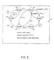
- Fig. 5 is an example of a state transition graph generated according to the present invention.
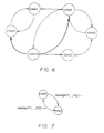
- Fig. 6 is a further exemplary display of a state transition graph with the current state and possible transitions from the current state all highlighted in bold.
- Fig. 7 is a simplified state transition graph with only two states.
- Fig. 8 is a flow diagram illustrating the method steps of the present invention.
- Fig. 1 is a block diagram illustrating the method and apparatus of the present invention.
- a network management system 14 monitors a live network 10 via communication link 12 over a period of time and passes the resulting network parameter data to a data repository 18 via communication link 16. Over a period of time, streams of data (e.g., of the type shown in Fig. 2) accumulate in the data repository 18. Data processor 22 accesses this accumulated data from the data repository 18 via communication link 20.
- streams of data e.g., of the type shown in Fig. 2
- Data processor 22 accesses this accumulated data from the data repository 18 via communication link 20.
- method 1 , method 2 , ..., method n refer to existing methods of transforming the data in data repository 18 into view 1 , view 2 , ..., view n (collectively labeled 34) on graphical interface 32, via communication links 28.
- Fig. 3 shows examples of such prior art views, which may be pie graphs, bar graphs, and two dimensional graphs derived from the network parameters.
- the present invention comprises both a new method and a new view, which are shown in Fig. 1 as a "Method to Determine Network Behavior Patterns" 26 (within processor 22) and a "View of Network Behavior Patterns" 36 (within graphical display 32 via communication link 30).
- the new method solves the following problem: Given a current state of a network and an observation of key network parameters, what will be the next state? In order to solve this problem, we now define: the concept of a network state; examples of observable network parameters; and rules for predicting a transition from one state to another given the values for the network parameters.
- Fig. 4 shows an exemplary high-level topology view of a network containing multiple subnets and routers (as an example of live network 10 in Fig. 1).
- the group of twelve icons 1 on the left of the figure, and the group of sixteen icons 2 on the right, may be Ethernet subnets.
- a pair of routers 3. 4 near the center are connected to these two groups of subnets, respectively, and the routers themselves are connected to each other via a coupler 5.
- Note that other subnets and routers (not shown in Fig. 4) have trunks attached to the network via couplers 6 and 7, which in turn are connected to router 4.
- Router 3 has twelve ports with traffic flowing to and from the respective twelve subnets.
- watches may be placed on each of the twelve ports. These watches can measure the percentage of port utilization during a predetermined time interval.
- Fig. 2 shows a measured level of traffic on each of twelve ports P1, P2, ..., and P12, for a few minutes of time.
- Examples of network management systems capable of implementing such a watch are: 1) Sniffer, Network General Corporation, 4200 Bohannon Drive, Menlo Park, CA 94025; 2) NetMetrix.
- the network management system 14 may include network management platforms, network monitors, or basic low-level programs such as "Etherfind” on Sun workstations, or "Netsnoop” on Silicon Graphics IRIX workstations.
- Port utilization data measured for one month in the form of Fig. 2 would take up thousands of pages, and would not provide a general description of network behavior.
- the prior art methods allow transformation of the accumulated data into graphical views such as an x-y plot, pie graph, and bargraph (see Fig. 3.)
- the prior art averaging algorithm may be applied to the measured data in order to set alarm thresholds for each port.
- none of these methods allow a network administrator to understand overall patterns in network behavior or to predict network behavior.
- the method of the present invention transforms the numeric data in Fig. 2 into a state transition diagram (a.k.a. a deterministic finite automaton) that represents the overall behavior patterns of the network.
- Fig. 5 shows an example of such a state transition graph 40, wherein nodes 41-46 represent six possible network states and arcs 48 connecting the nodes represent trends in observable network parameters that result in a transition from one state to another state.
- the trends are labeled with one or more port numbers (from Fig. 2) each followed by a symbol which indicates how the observed parameter is changing.
- the states are represented as nodes and embody the twelve parameters (where each parameter represents traffic at one of the twelve ports).
- each parameter may be an interval [x, y], where x represents a lower bound of port utilization and y represents an upper bound, over a predetermined time period.
- a network state for the data of Fig. 2 may be represented as follows: The different states and trends are determined based on historic data and any one of the supervised or unsupervised learning methods described hereinafter.
- the current numeric values on the ports P1, P2, ..., P12 are measured in short time increments, for example 10 minutes.
- a simple process may be used to translate the numeric values into symbolic values.
- the language of the symbolic values that represent trends in current network parameters is as follows:
- a prediction of future network behavior is determined from the state transition graph, the current state of the network, and the current network trends. For example, in the state transition graph of Fig. 5, if the network were in state 1 and a measurement of the current network parameters indicates that utilization of port 3 is increasing quickly, the present method would predict that the network will enter state 4. Upon transition to state 4, the network can either make a transition to state 3 or state 5, or return to state 1.
- the present method labels the states according to a performance criterion.
- state 3 were designated a "bad" state
- state 4 would be a potentially problematic state because state 4 could enter the bad state if the utilization on port 6 were to increase quickly.
- the present method warns the network administrator of potentially problematic states.
- the present method may display all of the derived information concerning the network behavior patterns to the user, i.e., the state transition graph, the current state, and the possible future states.
- Fig. 6 shows an exemplary display of a state transition graph where state 4 is highlighted as the current state. Also, the possible transitions via the arcs from state 4 are highlighted to emphasize the possible next states.
- the current state and the possible future states may be color coded on the display.
- labels corresponding to a predetermined performance criterion may be provided to the user.
- the method of this invention has taken a history of network behavior as embodied for example in the data of Fig. 2 and has transformed it into a state transition diagram as in Fig. 5. This transformation is referred to generally as "learning.”
- learning Several methods of learning exist, but the two main classes of learning being known as “supervised” and “unsupervised.”
- labels are applied to the numeric data at each time increment. Labels may depict a performance criterion, and examples of such labels are "good,” “bad,” “state 1,” and “evening state.”
- a supervised learning algorithm generalizes over particular network parameters in order to produce a concept of a "good” state, or a "bad” state, according to the performance criterion.
- each line of the network parameters in Fig. 2 were classified into one of ten states, where the states are labelled with numeric values, for example, 1, 2, ..., 10. (Note that this labelling is what characterizes this pseudo-code as "supervised” learning.) Then, an extra column in Fig. 2 would hold the classification of the lines of data.
- Each line of data in Fig. 2 may be characterized as a training pair (x,d). where x is a training sample (i.e., the original line) and d is a desired output (i.e., the classification). Given a table of training pairs, the learning algorithm proceeds as follows:
- the algorithm learns to classify each line of the training data into the correct state, and also to classify future lines of data into corresponding states.
- a similar algorithm may be used to learn the transitions or trends from one state to another.
- Fig. 7 shows yet another alternative embodiment of a simple daytime/nighttime transition diagram, wherein state 1 may represent the daytime state, and state 2 the nighttime state.
- the present method translates the average of activity on all ports of the network at any time increment into the above-defined symbolic language. Thus, if the network represented in the state transition graph of Fig. 7 is in state 1 and the average is decreasing quickly, the present method would predict that the network will enter the nighttime state.
- Fig. 8 is a flow chart summarizing various aspects of the present invention. To the left of vertical line 50, are steps 53-55 for "learning" network behavior. To the right of line 50, are steps 56-59 for "predicting" network behavior.
- the method begins at step 52 and proceeds to step 53 to read a history of network parameters from the data repository 18. The method then proceeds to step 54 to calculate/display a range of network states, and optionally identify the states as "bad,” “good,” “midday,” etc. The method then proceeds to step 55 to construct/display a state transition graph as shown for example, in Fig. 5. The method may end at step 60, or proceed further as described below.
- step 56 the method proceeds to step 56 to read current network parameters.
- the current network parameters are measured for a predetermined time period to determine/display the current state in step 57.
- the parameters are read for a sufficient time period to calculate/display the current trends in step 58.
- the method may then predict/display future network states in step 59.
- the arrows in the flow chart mean that the data produced by the box at the tail end of the arrow is required to perform the task in the box at the head of the arrow, e.g., the "predict/display future network states" box 59 requires as input the state transition graph 55, the current state 57, and the current trends 58.
- the user will execute the "learning network behavior" part of the method (to the left of dotted line 50), and later run the “predicting network behavior” (on the right side of line 50).
- the results of steps 54 and 55 are available for steps 57 and 59 respectively.
- the "predicting network behavior" part may be run continuously.
- a warning signal may be generated and displayed to the user to indicate that the network is moving toward a problematic state.
Landscapes
- Engineering & Computer Science (AREA)
- Computer Networks & Wireless Communication (AREA)
- Signal Processing (AREA)
- Data Exchanges In Wide-Area Networks (AREA)
- Management, Administration, Business Operations System, And Electronic Commerce (AREA)
Claims (14)
- Verfahren zum Ermitteln von Verhaltensmustern eines Netzwerks aus aufgelaufenen Netzwerkparametern, wobei das Verfahren die Schritte beinhaltet:a) Lesen (53) der aufgelaufenen Netzwerkparameter;b) Ermitteln (54) möglicher Zustände (40) des Netzwerks (10) aus den aufgelaufenen Netzwerkparametern;c) Ermitteln (54) möglicher Übergänge (40) zwischen den möglichen Zuständen; undd) einem Benutzer einen oder mehrere der möglichen Zustände und der möglichen Übergänge anzeigen (55).
- Verfahren nach Anspruch 1, das weiterhin beinhaltet:Messen (56) momentaner Netzwerkparameter für eine vorbestimmte Zeitdauer;Ermitteln (57) eines momentanen Zustands des Netzwerks (10) aus den momentanen Netzwerkparametern und den mögliche Zuständen; undeinem Benutzer den momentanen Zustand anzeigen (57).
- Verfahren nach Anspruch 2, das weiterhin beinhaltet:Ermitteln (58) momentaner Trends des Netzwerks (10) aus den momentanen Netzwerkparametern und den möglichen Übergängen;Voraussagen (59) möglicher nächster Zustände, in die das Netzwerk übergehen kann, aus den möglichen Zuständen, den möglichen Übergängen, dem momentanen Zustand und den momentanen Trends; undeinem Benutzer wenigstens die momentanen Trends oder möglichen nächsten Zustände anzeigen (59).
- Verfahren nach Anspruch 3, das weiterhin beinhaltet:
Bezeichnen (59) wenigstens der möglichen Zustände, der möglichen Übergänge, des momentanen Zustands, der möglichen nächsten Zustände oder der momentanen Trends gemäß einem Leistungskriterium. - Verfahren nach Anspruch 3, das weiterhin beinhaltet:Kennzeichnen (59) wenigstens eines der möglichen Zustände als einen problematischen Zustand; undeinen Benützer warnen (59), wenn einer der möglichen nächsten Zustände ein problematischer Zustand ist.
- Verfahren nach Anspruch 1, das weiterhin die Schritte beinhaltet:Messen der aufgelaufenen Netzwerkparameter aus dem Netzwerk für eine erste vorbestimmte Zeitdauer; undSpeichern der aufgelaufenen Netzwerkparameter in einem Datenspeicher (18);wobei Schritt a) das Lesen der aufgelaufenen Netzwerkparameter aus dem Datenspeicher (18) beinhaltet.
- Verfahren nach Anspruch 6, das weiterhin beinhaltet:Messen der momentanen Netzwerkparameter für eine zweite vorbestimmte Zeitdauer;Ermitteln (57) eines momentanen Zustands des Netzwerks aus den momentanen Netzwerkparametern und den möglichen Zuständen; undeinem Benutzer den momentanen Zustand anzeigen (57).
- Verfahren nach Anspruch 1, bei dem der Schritt des Ermittelns (54) möglicher Übergänge (40) das Ermitteln der möglichen Übergänge basierend auf den aufgelaufenen Netzwerkparametern beinhaltet.
- Vorrichtung zum Lesen aufgelaufener Netzwerkparameter aus einem Datenspeicher (18) eines Netzwerkmanagementsystems (14) und zum Bereitstellen einer Beschreibung von Verhaltensmustern des Netzwerks (10), wobei die Vorrichtung aufweist:einen Datenleser (22), der an den Datenspeicher (18) gekoppelt ist und der ausgebildet ist, die aufgelaufenen Netzwerkparameter einzulesen;einen Verhaltensanalysator (26), der an den Datenleser gekoppelt ist und der betriebsbereit ist, mögliche Zustände des Netzwerks basierend auf den aufgelaufenen Netzwerkparametern und möglichen Übergängen zwischen den möglichen Zustandsparametern zu ermitteln; undeine an den Netzwerkverhaltensanalysator (26) gekoppelte Zustandsanzeige (36), welche dazu ausgebildet ist, einem Benutzer eine sichtbare Anzeige eines oder mehrerer der möglichen Zustände und der möglichen Übergänge zu übermitteln.
- Vorrichtung nach Anspruch 9, die weiterhin aufweist:eine Überwachungseinrichtung (14), die an das Netzwerk (10) gekoppelt ist und die betriebsbereit ist, momentane Netzwerkparameter für eine vorbestimmte Zeitdauer zu messen;einen Statusanalysator (57), der an die Überwachungseinrichtung (14) und den Verhaltensanalysator gekoppelt ist und der betriebsbereit ist, einen momentanen Zustand des Netzwerks (10) aus den momentanen Netzwerkparametern und den möglichen Zuständen zu ermitteln; undeine Momentan-Status-Anzeige, die an den Statusanalysator (36) gekoppelt ist, und die betriebsbereit ist, einem Benutzer den momentanen Zustand zu übermitteln.
- Vorrichtung nach Anspruch 10, die weiterhin aufweist:einen Trendanalysator (58), der an die Überwachungseinrichtung und den Verhaltensanalysator gekoppelt ist und der betriebsbereit ist, momentane Trends des Netzwerks aus den momentanen Netzwerkparametern und den möglichen Übergängen zu ermitteln;eine Verhaltensvoraussageeinrichtung (59), die an den Statusanalysator, den Trendanalysator und den Verhaltensanalysator gekoppelt ist und die betriebsbereit ist, mögliche nächste Zustände, in die das Netzwerk übergehen kann, aus den möglichen Zuständen, den möglichen Übergängen, dem momentanen Zustand und den momentanen Trends zu ermitteln; undeine Voraussage-Anzeige (36), die an den Trendanalysator (58) und die Verhaltensvoraussageeinrichtung (59) gekoppelt ist und die betriebsbereit ist, einem Benutzer wenigstens die momentanen Trends oder die möglichen nächsten Zustände zu übermitteln.
- Vorrichtung nach Anspruch 11, die weiterhin aufweist:
einen Zustandsidentifizierer (59), der wenigstens an den Trendanalysator (58), den Statusanalysator (58) oder die Verhaltensvoraussageeinrichtung (59) gekoppelt ist und der ausgebildet ist, wenigstens die möglichen Zustände, die möglichen Übergänge, den momentanen Zustand, die möglichen nächsten Zustände oder die momentanen Trends gemäß einem Leistungskriterium zu bezeichnen. - Vorrichtung nach Anspruch 11, die weiterhin aufweist:einen Zustandsidentifizierer (54), der ausgebildet ist, wenigstens einen der möglichen Zustände als einen problematischen Zustand zu kennzeichnen; undeine Warneinheit (36), die an den Zustandsidentifizierer (54) gekoppelt ist und die betriebsbereit ist, einen Benutzer zu warnen, wenn einer der möglichen nächsten Zustände ein problematischer Zustand ist.
- Vorrichtung nach Anspruch 9, bei der der Verhaltensanalysator (26) dazu konstruiert und ausgebildet ist, die möglichen Übergänge basierend auf den aufgelaufenen Netzwerkparametern zu ermitteln.
Applications Claiming Priority (3)
| Application Number | Priority Date | Filing Date | Title |
|---|---|---|---|
| US38266695A | 1995-02-02 | 1995-02-02 | |
| US382666 | 1995-02-02 | ||
| PCT/US1996/001137 WO1996024210A2 (en) | 1995-02-02 | 1996-01-24 | Method and apparatus for learning network behavior trends and predicting future behavior of communications networks |
Publications (2)
| Publication Number | Publication Date |
|---|---|
| EP0807348A2 EP0807348A2 (de) | 1997-11-19 |
| EP0807348B1 true EP0807348B1 (de) | 2000-03-22 |
Family
ID=23509910
Family Applications (1)
| Application Number | Title | Priority Date | Filing Date |
|---|---|---|---|
| EP96905247A Expired - Lifetime EP0807348B1 (de) | 1995-02-02 | 1996-01-24 | Verfahren und anordnung zum lernen von verhaltentrends von netzwerken und vorhersagen des zukünftigen verhaltens von datenübertagungsnetzwerken |
Country Status (6)
| Country | Link |
|---|---|
| US (1) | US5987442A (de) |
| EP (1) | EP0807348B1 (de) |
| AT (1) | ATE191112T1 (de) |
| AU (1) | AU692369B2 (de) |
| DE (1) | DE69607324T2 (de) |
| WO (1) | WO1996024210A2 (de) |
Families Citing this family (56)
| Publication number | Priority date | Publication date | Assignee | Title |
|---|---|---|---|---|
| EP0849911A3 (de) * | 1996-12-18 | 1999-02-10 | Nortel Networks Corporation | Überwachung eines Kommunikationsnetz |
| US6108310A (en) * | 1997-09-12 | 2000-08-22 | Hewlett-Packard Company | Display of network traffic attributes based on frequency distribution |
| US6430615B1 (en) * | 1998-03-13 | 2002-08-06 | International Business Machines Corporation | Predictive model-based measurement acquisition employing a predictive model operating on a manager system and a managed system |
| US6556659B1 (en) | 1999-06-02 | 2003-04-29 | Accenture Llp | Service level management in a hybrid network architecture |
| US6147975A (en) * | 1999-06-02 | 2000-11-14 | Ac Properties B.V. | System, method and article of manufacture of a proactive threhold manager in a hybrid communication system architecture |
| US6597777B1 (en) | 1999-06-29 | 2003-07-22 | Lucent Technologies Inc. | Method and apparatus for detecting service anomalies in transaction-oriented networks |
| WO2001017169A2 (en) * | 1999-08-31 | 2001-03-08 | Accenture Llp | A system, method and article of manufacture for a network-based predictive fault management system |
| US6694362B1 (en) | 2000-01-03 | 2004-02-17 | Micromuse Inc. | Method and system for network event impact analysis and correlation with network administrators, management policies and procedures |
| US7752024B2 (en) * | 2000-05-05 | 2010-07-06 | Computer Associates Think, Inc. | Systems and methods for constructing multi-layer topological models of computer networks |
| WO2001086775A1 (en) * | 2000-05-05 | 2001-11-15 | Aprisma Management Technologies, Inc. | Help desk systems and methods for use with communications networks |
| US7237138B2 (en) * | 2000-05-05 | 2007-06-26 | Computer Associates Think, Inc. | Systems and methods for diagnosing faults in computer networks |
| US7500143B2 (en) * | 2000-05-05 | 2009-03-03 | Computer Associates Think, Inc. | Systems and methods for managing and analyzing faults in computer networks |
| WO2001086380A2 (en) * | 2000-05-05 | 2001-11-15 | Aprisma Management Technologies, Inc. | Systems and methods for isolating faults in computer networks |
| GB2357391B (en) * | 2000-05-12 | 2003-09-24 | Ericsson Telefon Ab L M | Telecommunications network |
| US20010051862A1 (en) * | 2000-06-09 | 2001-12-13 | Fujitsu Limited | Simulator, simulation method, and a computer product |
| FI114749B (fi) * | 2000-09-11 | 2004-12-15 | Nokia Corp | Poikkeamien ilmaisujärjestelmä ja menetelmä sen opettamiseksi |
| US7278104B1 (en) * | 2000-11-02 | 2007-10-02 | Lucent Technologies Inc. | Graphical user interface for managing network elements |
| US7383191B1 (en) | 2000-11-28 | 2008-06-03 | International Business Machines Corporation | Method and system for predicting causes of network service outages using time domain correlation |
| US7305485B2 (en) * | 2000-12-15 | 2007-12-04 | International Business Machines Corporation | Method and system for network management with per-endpoint adaptive data communication based on application life cycle |
| US7165231B2 (en) * | 2000-12-18 | 2007-01-16 | Yardstick Research, Llc | Method and system for incremental behavioral validation of digital design expressed in hardware description language |
| US7107339B1 (en) * | 2001-04-07 | 2006-09-12 | Webmethods, Inc. | Predictive monitoring and problem identification in an information technology (IT) infrastructure |
| US20020174217A1 (en) * | 2001-05-18 | 2002-11-21 | Gateway, Inc. | System and method for predicting network performance |
| US6744739B2 (en) | 2001-05-18 | 2004-06-01 | Micromuse Inc. | Method and system for determining network characteristics using routing protocols |
| US7043727B2 (en) | 2001-06-08 | 2006-05-09 | Micromuse Ltd. | Method and system for efficient distribution of network event data |
| US7516208B1 (en) | 2001-07-20 | 2009-04-07 | International Business Machines Corporation | Event database management method and system for network event reporting system |
| EP1280298A1 (de) * | 2001-07-26 | 2003-01-29 | BRITISH TELECOMMUNICATIONS public limited company | Verfahren und Vorrichtung zum Detektieren von Netzwerkaktivitäten |
| US7822843B2 (en) * | 2001-08-13 | 2010-10-26 | Cox Communications, Inc. | Predicting the activities of an individual or group using minimal information |
| US7363368B2 (en) | 2001-12-24 | 2008-04-22 | International Business Machines Corporation | System and method for transaction recording and playback |
| AU2003228411A1 (en) * | 2002-03-29 | 2003-10-13 | Network Genomics, Inc. | Forward looking infrastructure re-provisioning |
| US20040213448A1 (en) * | 2003-04-28 | 2004-10-28 | Asn Technology Corp. | Apparatus for recognizing counterfeit currency and method thereof |
| US7602725B2 (en) * | 2003-07-11 | 2009-10-13 | Computer Associates Think, Inc. | System and method for aggregating real-time and historical data |
| EP1510952B1 (de) * | 2003-08-28 | 2007-02-14 | Accenture Global Services GmbH | Erfassung, Zusammenstellung und/oder Visualisierung von strukturellen Merkmalen von Architekturen |
| US7783740B2 (en) * | 2003-09-25 | 2010-08-24 | Rockwell Automation Technologies, Inc. | Embedded network traffic analyzer |
| ATE366011T1 (de) * | 2003-10-21 | 2007-07-15 | Hewlett Packard Development Co | Verfahren zur überwachung von computer systemen |
| US8015289B2 (en) * | 2003-12-11 | 2011-09-06 | Ziti Technologies Limited Liability Company | System and method predicting and managing network capacity requirements |
| US7929459B2 (en) * | 2004-10-19 | 2011-04-19 | At&T Mobility Ii Llc | Method and apparatus for automatically determining the manner in which to allocate available capital to achieve a desired level of network quality performance |
| WO2006076398A2 (en) * | 2005-01-12 | 2006-07-20 | Metier Ltd | Predictive analytic method and apparatus |
| JP2006285383A (ja) * | 2005-03-31 | 2006-10-19 | Nec Corp | 流行情報通知システムおよび流行情報通知方法 |
| US7643428B1 (en) * | 2005-11-09 | 2010-01-05 | Embarq Holdings Company, Llc | Early detection of faulty communications links |
| US7663626B2 (en) * | 2006-02-28 | 2010-02-16 | At&T Corp. | Method and apparatus for providing a network traffic composite graph |
| US7738377B1 (en) * | 2006-05-22 | 2010-06-15 | At&T Intellectual Property Ii, L.P. | Method and apparatus for volumetric thresholding and alarming on internet protocol traffic |
| EP1868320B1 (de) * | 2006-06-16 | 2010-08-11 | Groundhog Technologies Inc. | Verwaltungssystem und Verfahren für ein drahtloses Kommunikationsnetz und zugehörige grafische Benutzerschnittstelle |
| US7716146B2 (en) * | 2006-12-22 | 2010-05-11 | Verizon Patent And Licensing Inc. | Network management system utilizing a neural network |
| WO2009019691A2 (en) * | 2007-08-08 | 2009-02-12 | Yoram Kariv | System and method for predictive network monitoring |
| KR100935861B1 (ko) * | 2007-11-12 | 2010-01-07 | 한국전자통신연구원 | 네트워크 보안 위험도 예측 방법 및 장치 |
| KR101039717B1 (ko) | 2009-07-07 | 2011-06-09 | 한국전자통신연구원 | 사이버위협을 예측하기 위한 사이버위협 예측 엔진 시스템 및 상기 시스템을 이용한 사이버위협 예측 방법 |
| US9571342B2 (en) * | 2012-02-14 | 2017-02-14 | Inetco Systems Limited | Method and system for generating transaction data from network traffic data for an application system |
| WO2013177311A1 (en) * | 2012-05-23 | 2013-11-28 | Observable Networks, Llc | System and method for continuous device profiling (cdp) |
| US11049005B2 (en) * | 2017-03-22 | 2021-06-29 | At&T Intellectual Property I, L.P. | Methods, devices and systems for managing network video traffic |
| JP6863091B2 (ja) * | 2017-05-31 | 2021-04-21 | 富士通株式会社 | 管理装置、管理方法及び管理プログラム |
| CA3114288A1 (en) * | 2018-10-15 | 2020-04-23 | Netz Forecasts Ltd. | Systems and methods for network stabilization prediction |
| US11962475B2 (en) * | 2020-02-03 | 2024-04-16 | Telefonaktiebolaget Lm Ericsson (Publ) | Estimating properties of units using system state graph models |
| US12170608B2 (en) | 2022-06-21 | 2024-12-17 | Juniper Networks, Inc. | Link behavior prediction for use in path selection |
| US12164672B2 (en) | 2022-12-01 | 2024-12-10 | Bank Of America Corporation | System and method for analyzing micro-anomalies in anonymized electronic data |
| US12353945B2 (en) * | 2022-12-30 | 2025-07-08 | United Parcel Service Of America, Inc. | Detecting equipment state via tag-reader modulations |
| US12192272B1 (en) * | 2023-08-01 | 2025-01-07 | Dell Products L.P. | Frontend storage port rebalancing and allocation using machine learning techniques |
Family Cites Families (12)
| Publication number | Priority date | Publication date | Assignee | Title |
|---|---|---|---|---|
| US4727548A (en) * | 1986-09-08 | 1988-02-23 | Harris Corporation | On-line, limited mode, built-in fault detection/isolation system for state machines and combinational logic |
| US5251285A (en) * | 1988-03-25 | 1993-10-05 | Hitachi, Ltd. | Method and system for process control with complex inference mechanism using qualitative and quantitative reasoning |
| CA1335836C (en) * | 1988-07-07 | 1995-06-06 | Ichiro Iida | Adaptive routing system |
| CA2017974C (en) * | 1989-08-07 | 1998-06-16 | Richard Alan Becker | Dynamic graphical analysis of network data |
| US5159685A (en) * | 1989-12-06 | 1992-10-27 | Racal Data Communications Inc. | Expert system for communications network |
| JP2964507B2 (ja) * | 1989-12-12 | 1999-10-18 | 松下電器産業株式会社 | Hmm装置 |
| US5197127A (en) * | 1990-09-24 | 1993-03-23 | International Business Machines Corporation | Expert system method for performing window protocol-based data flow analysis within a data communication network |
| US5490266A (en) * | 1991-03-01 | 1996-02-06 | Altera Corporation | Process oriented logic simulation having stability checking |
| EP0503784B1 (de) * | 1991-03-12 | 1998-06-10 | Hewlett-Packard Company | Auf Hypothesen und Schlussfolgerungen basiertes Diagnoseverfahren von Datenkommunikationsnetzwerken |
| US5469553A (en) * | 1992-04-16 | 1995-11-21 | Quantum Corporation | Event driven power reducing software state machine |
| US5446874A (en) * | 1993-12-23 | 1995-08-29 | International Business Machines Corp. | Automated benchmarking with self customization |
| US5452215A (en) * | 1994-08-24 | 1995-09-19 | Ibm Business Machines Corporation | System and method for designing a finite state machine to reduce power dissipation |
-
1996
- 1996-01-24 EP EP96905247A patent/EP0807348B1/de not_active Expired - Lifetime
- 1996-01-24 AU AU49057/96A patent/AU692369B2/en not_active Ceased
- 1996-01-24 DE DE69607324T patent/DE69607324T2/de not_active Expired - Lifetime
- 1996-01-24 WO PCT/US1996/001137 patent/WO1996024210A2/en not_active Ceased
- 1996-01-24 AT AT96905247T patent/ATE191112T1/de not_active IP Right Cessation
-
1997
- 1997-10-24 US US08/960,076 patent/US5987442A/en not_active Expired - Lifetime
Also Published As
| Publication number | Publication date |
|---|---|
| AU692369B2 (en) | 1998-06-04 |
| EP0807348A2 (de) | 1997-11-19 |
| DE69607324D1 (de) | 2000-04-27 |
| AU4905796A (en) | 1996-08-21 |
| WO1996024210A3 (en) | 1996-11-07 |
| DE69607324T2 (de) | 2000-08-24 |
| WO1996024210A2 (en) | 1996-08-08 |
| US5987442A (en) | 1999-11-16 |
| ATE191112T1 (de) | 2000-04-15 |
Similar Documents
| Publication | Publication Date | Title |
|---|---|---|
| EP0807348B1 (de) | Verfahren und anordnung zum lernen von verhaltentrends von netzwerken und vorhersagen des zukünftigen verhaltens von datenübertagungsnetzwerken | |
| CN116684878B (zh) | 一种5g信息传输数据安全监测系统 | |
| CN105825271B (zh) | 基于证据推理的卫星故障诊断与预测方法 | |
| EP1374486A1 (de) | Methode für die konfiguration eines netwerkes durch die definierte bildung von clustern | |
| CN116051330B (zh) | 一种基于大数据的智慧校园安全管理系统及方法 | |
| US20250037515A1 (en) | Self-diagnosis for in-vehicle networks | |
| CN117014471A (zh) | 一种基于人工智能的工程物联网安全监测系统 | |
| CN114595540B (zh) | 一种自主式交通系统可靠性评估方法 | |
| CN119449651B (zh) | 一种基于人工智能的云计算的数据处理方法 | |
| CN119211079B (zh) | 一种云上可用区网络丢包的处理方法、系统、设备及介质 | |
| CN119996230B (zh) | 一种智能容灾管理服务系统 | |
| CN120276903A (zh) | 一种云平台告警根因定位方法、装置、设备以及存储介质 | |
| CN120559397A (zh) | 用于供电电路的集成故障监测方法及平台 | |
| CN120128697A (zh) | 一种基于边缘计算的智能终端监测系统及方法 | |
| EP3576349B1 (de) | Zustandsüberwachung drahtloser netzwerke in industrieanlagen | |
| CN119071672A (zh) | 一种哑资源端子大数据的智能分析方法、设备及介质 | |
| KR20230138241A (ko) | 분산 클라우드 기반의 데이터 플랫폼을 위한 시스템 및 이를 위한 동작 방법 | |
| CN120091354B (zh) | 一种用于实现车载设备的数据集成方法及系统 | |
| CN119012208B (zh) | 一种应用于无人机的通信数据管理系统及方法 | |
| CN120494431B (zh) | 基于大模型的数据协同处理方法及系统 | |
| CN120523685A (zh) | 一种服务器性能确定方法、装置、设备及介质 | |
| CN121682716A (zh) | 基于宏微逾渗特征与多模态深度学习融合的风险识别系统 | |
| CN120956637A (zh) | 一种基于流量分析的web服务质量控制方法 | |
| CN119996259A (zh) | 分布式网络延迟测量方法与系统 | |
| CN116311950A (zh) | 路径选择方法和基于虚实融合技术的v2x测试系统 |
Legal Events
| Date | Code | Title | Description |
|---|---|---|---|
| PUAI | Public reference made under article 153(3) epc to a published international application that has entered the european phase |
Free format text: ORIGINAL CODE: 0009012 |
|
| 17P | Request for examination filed |
Effective date: 19970728 |
|
| AK | Designated contracting states |
Kind code of ref document: A2 Designated state(s): AT BE CH DE DK ES FR GB GR IE IT LI LU MC NL PT SE |
|
| 17Q | First examination report despatched |
Effective date: 19980423 |
|
| GRAG | Despatch of communication of intention to grant |
Free format text: ORIGINAL CODE: EPIDOS AGRA |
|
| GRAG | Despatch of communication of intention to grant |
Free format text: ORIGINAL CODE: EPIDOS AGRA |
|
| GRAH | Despatch of communication of intention to grant a patent |
Free format text: ORIGINAL CODE: EPIDOS IGRA |
|
| GRAH | Despatch of communication of intention to grant a patent |
Free format text: ORIGINAL CODE: EPIDOS IGRA |
|
| GRAA | (expected) grant |
Free format text: ORIGINAL CODE: 0009210 |
|
| AK | Designated contracting states |
Kind code of ref document: B1 Designated state(s): AT BE CH DE DK ES FR GB GR IE IT LI LU MC NL PT SE |
|
| PG25 | Lapsed in a contracting state [announced via postgrant information from national office to epo] |
Ref country code: SE Free format text: THE PATENT HAS BEEN ANNULLED BY A DECISION OF A NATIONAL AUTHORITY Effective date: 20000322 Ref country code: NL Free format text: LAPSE BECAUSE OF FAILURE TO SUBMIT A TRANSLATION OF THE DESCRIPTION OR TO PAY THE FEE WITHIN THE PRESCRIBED TIME-LIMIT Effective date: 20000322 Ref country code: LI Free format text: LAPSE BECAUSE OF NON-PAYMENT OF DUE FEES Effective date: 20000322 Ref country code: IT Free format text: LAPSE BECAUSE OF FAILURE TO SUBMIT A TRANSLATION OF THE DESCRIPTION OR TO PAY THE FEE WITHIN THE PRESCRIBED TIME-LIMIT;WARNING: LAPSES OF ITALIAN PATENTS WITH EFFECTIVE DATE BEFORE 2007 MAY HAVE OCCURRED AT ANY TIME BEFORE 2007. THE CORRECT EFFECTIVE DATE MAY BE DIFFERENT FROM THE ONE RECORDED. Effective date: 20000322 Ref country code: ES Free format text: THE PATENT HAS BEEN ANNULLED BY A DECISION OF A NATIONAL AUTHORITY Effective date: 20000322 Ref country code: CH Free format text: LAPSE BECAUSE OF NON-PAYMENT OF DUE FEES Effective date: 20000322 Ref country code: BE Free format text: LAPSE BECAUSE OF FAILURE TO SUBMIT A TRANSLATION OF THE DESCRIPTION OR TO PAY THE FEE WITHIN THE PRESCRIBED TIME-LIMIT Effective date: 20000322 Ref country code: AT Free format text: LAPSE BECAUSE OF FAILURE TO SUBMIT A TRANSLATION OF THE DESCRIPTION OR TO PAY THE FEE WITHIN THE PRESCRIBED TIME-LIMIT Effective date: 20000322 |
|
| REF | Corresponds to: |
Ref document number: 191112 Country of ref document: AT Date of ref document: 20000415 Kind code of ref document: T |
|
| REG | Reference to a national code |
Ref country code: CH Ref legal event code: EP |
|
| REF | Corresponds to: |
Ref document number: 69607324 Country of ref document: DE Date of ref document: 20000427 |
|
| REG | Reference to a national code |
Ref country code: IE Ref legal event code: FG4D |
|
| PG25 | Lapsed in a contracting state [announced via postgrant information from national office to epo] |
Ref country code: DK Free format text: LAPSE BECAUSE OF FAILURE TO SUBMIT A TRANSLATION OF THE DESCRIPTION OR TO PAY THE FEE WITHIN THE PRESCRIBED TIME-LIMIT Effective date: 20000622 |
|
| ET | Fr: translation filed | ||
| PG25 | Lapsed in a contracting state [announced via postgrant information from national office to epo] |
Ref country code: PT Free format text: LAPSE BECAUSE OF FAILURE TO SUBMIT A TRANSLATION OF THE DESCRIPTION OR TO PAY THE FEE WITHIN THE PRESCRIBED TIME-LIMIT Effective date: 20000623 Ref country code: GR Free format text: LAPSE BECAUSE OF FAILURE TO SUBMIT A TRANSLATION OF THE DESCRIPTION OR TO PAY THE FEE WITHIN THE PRESCRIBED TIME-LIMIT Effective date: 20000623 |
|
| NLV1 | Nl: lapsed or annulled due to failure to fulfill the requirements of art. 29p and 29m of the patents act | ||
| REG | Reference to a national code |
Ref country code: CH Ref legal event code: PL |
|
| PLBE | No opposition filed within time limit |
Free format text: ORIGINAL CODE: 0009261 |
|
| STAA | Information on the status of an ep patent application or granted ep patent |
Free format text: STATUS: NO OPPOSITION FILED WITHIN TIME LIMIT |
|
| PG25 | Lapsed in a contracting state [announced via postgrant information from national office to epo] |
Ref country code: LU Free format text: LAPSE BECAUSE OF NON-PAYMENT OF DUE FEES Effective date: 20010124 Ref country code: IE Free format text: LAPSE BECAUSE OF NON-PAYMENT OF DUE FEES Effective date: 20010124 |
|
| PG25 | Lapsed in a contracting state [announced via postgrant information from national office to epo] |
Ref country code: MC Free format text: LAPSE BECAUSE OF NON-PAYMENT OF DUE FEES Effective date: 20010131 |
|
| 26N | No opposition filed | ||
| REG | Reference to a national code |
Ref country code: IE Ref legal event code: MM4A |
|
| REG | Reference to a national code |
Ref country code: GB Ref legal event code: IF02 |
|
| REG | Reference to a national code |
Ref country code: GB Ref legal event code: 732E |
|
| REG | Reference to a national code |
Ref country code: FR Ref legal event code: TP |
|
| PGFP | Annual fee paid to national office [announced via postgrant information from national office to epo] |
Ref country code: GB Payment date: 20080123 Year of fee payment: 13 |
|
| PGFP | Annual fee paid to national office [announced via postgrant information from national office to epo] |
Ref country code: FR Payment date: 20080108 Year of fee payment: 13 |
|
| GBPC | Gb: european patent ceased through non-payment of renewal fee |
Effective date: 20090124 |
|
| REG | Reference to a national code |
Ref country code: FR Ref legal event code: ST Effective date: 20091030 |
|
| PG25 | Lapsed in a contracting state [announced via postgrant information from national office to epo] |
Ref country code: GB Free format text: LAPSE BECAUSE OF NON-PAYMENT OF DUE FEES Effective date: 20090124 |
|
| PG25 | Lapsed in a contracting state [announced via postgrant information from national office to epo] |
Ref country code: FR Free format text: LAPSE BECAUSE OF NON-PAYMENT OF DUE FEES Effective date: 20090202 |
|
| PGFP | Annual fee paid to national office [announced via postgrant information from national office to epo] |
Ref country code: DE Payment date: 20140122 Year of fee payment: 19 |
|
| REG | Reference to a national code |
Ref country code: DE Ref legal event code: R119 Ref document number: 69607324 Country of ref document: DE |
|
| PG25 | Lapsed in a contracting state [announced via postgrant information from national office to epo] |
Ref country code: DE Free format text: LAPSE BECAUSE OF NON-PAYMENT OF DUE FEES Effective date: 20150801 |