EP1868221A2 - Method of manufacturing a cathode for cathode ray tubes - Google Patents
Method of manufacturing a cathode for cathode ray tubes Download PDFInfo
- Publication number
- EP1868221A2 EP1868221A2 EP07106047A EP07106047A EP1868221A2 EP 1868221 A2 EP1868221 A2 EP 1868221A2 EP 07106047 A EP07106047 A EP 07106047A EP 07106047 A EP07106047 A EP 07106047A EP 1868221 A2 EP1868221 A2 EP 1868221A2
- Authority
- EP
- European Patent Office
- Prior art keywords
- skirts
- cathode
- chemical attack
- skirt
- manufacturing according
- Prior art date
- Legal status (The legal status is an assumption and is not a legal conclusion. Google has not performed a legal analysis and makes no representation as to the accuracy of the status listed.)
- Withdrawn
Links
Images
Classifications
-
- H—ELECTRICITY
- H01—ELECTRIC ELEMENTS
- H01J—ELECTRIC DISCHARGE TUBES OR DISCHARGE LAMPS
- H01J9/00—Apparatus or processes specially adapted for the manufacture, installation, removal, maintenance of electric discharge tubes, discharge lamps, or parts thereof; Recovery of material from discharge tubes or lamps
- H01J9/02—Manufacture of electrodes or electrode systems
- H01J9/04—Manufacture of electrodes or electrode systems of thermionic cathodes
-
- H—ELECTRICITY
- H01—ELECTRIC ELEMENTS
- H01J—ELECTRIC DISCHARGE TUBES OR DISCHARGE LAMPS
- H01J1/00—Details of electrodes, of magnetic control means, of screens, or of the mounting or spacing thereof, common to two or more basic types of discharge tubes or lamps
- H01J1/02—Main electrodes
- H01J1/13—Solid thermionic cathodes
- H01J1/20—Cathodes heated indirectly by an electric current; Cathodes heated by electron or ion bombardment
- H01J1/28—Dispenser-type cathodes, e.g. L-cathode
Definitions
- the invention relates to a method for manufacturing cathodes for cathode ray tubes and an electron gun obtained by this method. It is notably applicable to low power cathodes in which the sleeve containing the heating filament and its cup are manufactured separately.
- Cathodes for electron guns of cathode ray tubes comprise a skirt (or sleeve) designed to contain the heating filament of the cathode.
- a cup designed to receive the emissive layer of the cathode is fitted on the skirt.
- the skirts have a very low wall thickness.
- the thickness for NiCr skirts can be less than 18 micrometres at the level of the small diameter of the skirts (cup fitting diameter).
- these skirts during their manufacture by stamping and drawing out, are cold worked and have smooth outer surfaces that have a very low level of roughness.
- the skirts After being shaped, the skirts are annealed at an approximate temperature of 1050°C.
- the skirts are placed in bulk in a boat. They therefore tend to stick to one another through a mechanism of local sintering. Owing to the low thickness of their wall, it is therefore very difficult to separate them and there is a frequent risk of deforming or even piercing them.
- the purpose of the invention is to resolve this problem.
- the invention therefore relates to a method of manufacturing cathode skirts of electron guns comprising a thermal annealing step followed by an assembly step for each skirt of a cup designed to bear the electro-emissive zone of the cathode.
- the method according to the invention comprises, before the said thermal annealing, a realisation step of surface irregularities on the outer face of each skirt.
- This irregularity realisation step preferably comprises a chemical attack step.
- this irregularity realisation step can also be carried out by an oxidation step of the outer face of each skirt.
- this step is preferably performed collectively on a batch of skirts and the chemical attack step is followed by a rinsing step followed by a drying step.
- the said chemical attack is realised using a solution of hydrochloric acid.
- the concentration of the said solution in hydrochloric acid is advantageously between 30 and 37%.
- the hydrochloric acid solution temperature is advantageously between 20°C and 40°C and can thus provide for the chemical attack step to be between 15 and 45 minutes.
- the concentration in acid of the said solution of hydrochloric acid is 37%
- the temperature of the acid solution is 22°C
- the duration of the chemical attack is 30 minutes.
- the said chemical attack can also be realised using a solution of acetic acid and nitric acid.
- the following volume composition of the said solution can be provided:
- the temperature of the acetic acid and nitric acid solution is between 80°C and 110°C, and that the duration of the chemical attack is between 15 and 45 minutes.
- the temperature of the acetic acid and nitric acid solution is about 100°C and the duration of the chemical attack step is about 30 minutes.
- the method according to the invention comprises the following steps:
- the invention is also applicable to an electron gun for cathode ray tubes realised by means of the method thus described.
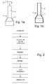
- Figure 1a shows an example of a skirt of a cathode such as can be found in the art in the low power cathodes.
- the skirt 1 comprises a widened part 11 for attaching the cathode to the electron gun and a shrunken part 10.
- the top extremity of the shrunken part 10 is not closed.
- a cup 2 is therefore provided which is placed on the extremity of the skirt 1 according to the direction of the arrow indicated in figure 1a. This cup is designed to receive the emissive material of the cathode.
- the skirt 1 is manufactured by stamping and drawing out.
- the diameter of the shrunken part 10 is typically in the order of a millimetre and the thickness of the wall of this part 10 is about 18 micrometres.
- skirts thus manufactured is placed in bulk in a boat to undergo annealing at around 1000°C.
- the skirts then tend to stick to one another.
- the skirts Owing to the small thickness of the walls of the skirts, the skirts have a certain fragility.
- the invention thus provides, after the realisation step of the skirts by stamping and before the annealing step, an attack step of the outer surface of the skirts enabling skirts to be obtained having an outer surface presenting sufficient roughness so that the number of contact points between the skirts is reduced when they are placed in bulk in the boat with a view to annealing.
- This attack of the outer surface of the skirts can be carried out by oxidation, by sand blasting or by chemical attack.
- Figure 2 shows the method of the invention using a chemical attack method.
- the NiCr skirts undergo a chemical attack in a bath of acid for a duration comprising between 15 and 45 minutes.
- the method then provides for a rinsing step in a current of deionised water at a temperature of between 60°C and 80°C for a duration of 10 to 30 minutes.
- Cups such as the cup 2, are assembled on the extremities of the skirts (by laser welding for example).
- the acid used is a hydrochloric acid.
- the concentration is between 30 and 37% of hydrochloric acid.
- the temperature of the acid bath in which the skirts are immersed can be between 20°C and 40°C, namely almost at ambient temperature.
- the period of treatment in an acid bath is approximately between 15 and 45 minutes.
- an HCl acid can be used at a concentration of about 37% and this chemical attack step will be carried out at a temperature close to 22°C for approximately 30 minutes.
- a solution of glacial acetic acid, nitric acid and water is used.
- the volume composition of this solution will be as follows:
- the treatment will be carried out at a temperature of between 80°C and 110°C for 15 to 45 minutes.
- the treatment will be carried out at around 100°C (103°C for example) for 30 minutes.
- the measurement of the said roughness accounted for in the present invention is the statistical criterion R a that represents the arithmetical average deviation from the mean with respect to the mean line of the surface profile.
- an Ra value of at least 0.25 ⁇ m will prevent the tendency that the skirts have to stick together when they are undergoing annealing when their surface is not treated.
- composition of the acid baths, their temperature and the duration of the chemical attack must be optimised in accordance with the invention to prevent the roughnesses from being smoothed by an attack that is too powerful or too long.
- the NiCr is reconstructed and the skirt matt and rough after attack becomes smooth and glossy after annealing.
Landscapes
- Engineering & Computer Science (AREA)
- Manufacturing & Machinery (AREA)
- ing And Chemical Polishing (AREA)
- Manufacture Of Electron Tubes, Discharge Lamp Vessels, Lead-In Wires, And The Like (AREA)
Abstract
Description
- The invention relates to a method for manufacturing cathodes for cathode ray tubes and an electron gun obtained by this method. It is notably applicable to low power cathodes in which the sleeve containing the heating filament and its cup are manufactured separately.
- Cathodes for electron guns of cathode ray tubes comprise a skirt (or sleeve) designed to contain the heating filament of the cathode.
- In some cathodes, notably in the low power guns, a cup designed to receive the emissive layer of the cathode is fitted on the skirt.
- The skirts have a very low wall thickness. For example, the thickness for NiCr skirts can be less than 18 micrometres at the level of the small diameter of the skirts (cup fitting diameter). Moreover, these skirts, during their manufacture by stamping and drawing out, are cold worked and have smooth outer surfaces that have a very low level of roughness.
- After being shaped, the skirts are annealed at an approximate temperature of 1050°C. Currently, for this annealing operation, the skirts are placed in bulk in a boat. They therefore tend to stick to one another through a mechanism of local sintering. Owing to the low thickness of their wall, it is therefore very difficult to separate them and there is a frequent risk of deforming or even piercing them.
- The purpose of the invention is to resolve this problem.
- The invention therefore relates to a method of manufacturing cathode skirts of electron guns comprising a thermal annealing step followed by an assembly step for each skirt of a cup designed to bear the electro-emissive zone of the cathode. The method according to the invention comprises, before the said thermal annealing, a realisation step of surface irregularities on the outer face of each skirt.
- This irregularity realisation step preferably comprises a chemical attack step.
- However, this irregularity realisation step can also be carried out by an oxidation step of the outer face of each skirt.
- If the method has recourse to a chemical attack step, this step is preferably performed collectively on a batch of skirts and the chemical attack step is followed by a rinsing step followed by a drying step.
- According to one embodiment of the invention method, the said chemical attack is realised using a solution of hydrochloric acid.
- In this case, the concentration of the said solution in hydrochloric acid is advantageously between 30 and 37%.
- With such an acid concentration, the hydrochloric acid solution temperature is advantageously between 20°C and 40°C and can thus provide for the chemical attack step to be between 15 and 45 minutes.
- According to one preferred embodiment of the invention the concentration in acid of the said solution of hydrochloric acid is 37%, the temperature of the acid solution is 22°C, and the duration of the chemical attack is 30 minutes.
- According to one embodiment variation of the invention, the said chemical attack can also be realised using a solution of acetic acid and nitric acid.
- According to this embodiment variation, the following volume composition of the said solution can be provided:
- acetic acid: 40%
- nitric acid: 0.2%
- water: 59.8%.
- According to one preferred embodiment of the invention, it can therefore be provided advantageously that the temperature of the acetic acid and nitric acid solution is between 80°C and 110°C, and that the duration of the chemical attack is between 15 and 45 minutes.
- More precisely, it can be provided that the temperature of the acetic acid and nitric acid solution is about 100°C and the duration of the chemical attack step is about 30 minutes.
- Generally, the method according to the invention comprises the following steps:
- chemical attack on the skirts,
- washing the skirts,
- drying the skirts,
- assembling cups on the skirts,
- annealing the skirts.
- The invention is also applicable to an electron gun for cathode ray tubes realised by means of the method thus described.
- The different objects and characteristics of the invention will appear more clearly in the description that follows as well as in the annexed figures, wherein:
- figures 1a and 1b, an example of a cathode to which the invention applies,
- figure 2, a diagram of the manufacturing method according to the invention.
- Figure 1a shows an example of a skirt of a cathode such as can be found in the art in the low power cathodes. The
skirt 1 comprises a widenedpart 11 for attaching the cathode to the electron gun and ashrunken part 10. As can be seen in figure 1b, the top extremity of theshrunken part 10 is not closed. A cup 2 is therefore provided which is placed on the extremity of theskirt 1 according to the direction of the arrow indicated in figure 1a. This cup is designed to receive the emissive material of the cathode. - The
skirt 1 is manufactured by stamping and drawing out. The diameter of theshrunken part 10 is typically in the order of a millimetre and the thickness of the wall of thispart 10 is about 18 micrometres. - As has been explained above, a batch of skirts thus manufactured is placed in bulk in a boat to undergo annealing at around 1000°C. The skirts then tend to stick to one another. Owing to the small thickness of the walls of the skirts, the skirts have a certain fragility.
- To overcome this disadvantage, the invention thus provides, after the realisation step of the skirts by stamping and before the annealing step, an attack step of the outer surface of the skirts enabling skirts to be obtained having an outer surface presenting sufficient roughness so that the number of contact points between the skirts is reduced when they are placed in bulk in the boat with a view to annealing.
- This attack of the outer surface of the skirts can be carried out by oxidation, by sand blasting or by chemical attack.
- Figure 2 shows the method of the invention using a chemical attack method. According to the invention, after stamping, the NiCr skirts undergo a chemical attack in a bath of acid for a duration comprising between 15 and 45 minutes.
- The method then provides for a rinsing step in a current of deionised water at a temperature of between 60°C and 80°C for a duration of 10 to 30 minutes.
- Next, a drying step at a temperature of between 140°C and 160°C for 4 to 8 hours.
- Cups, such as the cup 2, are assembled on the extremities of the skirts (by laser welding for example).
- One can then proceed with the annealing step of the skirts at a temperature close to or greater than 1000°C.
- According to a preferred embodiment, the acid used is a hydrochloric acid.
- For example the concentration is between 30 and 37% of hydrochloric acid. The temperature of the acid bath in which the skirts are immersed can be between 20°C and 40°C, namely almost at ambient temperature. The period of treatment in an acid bath is approximately between 15 and 45 minutes.
- Preferentially, an HCl acid can be used at a concentration of about 37% and this chemical attack step will be carried out at a temperature close to 22°C for approximately 30 minutes.
- According to one embodiment variation of the method of the invention, a solution of glacial acetic acid, nitric acid and water is used.
- According to one embodiment, the volume composition of this solution will be as follows:
- acetic acid: 40%
- water: 59.8%
- nitric acid: 0.2%
- With such an acid solution, the treatment will be carried out at a temperature of between 80°C and 110°C for 15 to 45 minutes.
- Preferentially, the treatment will be carried out at around 100°C (103°C for example) for 30 minutes.
- The chemical attack thus carried out according to the method of the invention enables a sufficient roughness to be reached.
- The measurement of the said roughness accounted for in the present invention is the statistical criterion Ra that represents the arithmetical average deviation from the mean with respect to the mean line of the surface profile.
- Hence, measured according to the ISO standard, an Ra value of at least 0.25 µm will prevent the tendency that the skirts have to stick together when they are undergoing annealing when their surface is not treated.
- The chemical attack nevertheless only moderately reduces the initial thickness of 18 micrometres of the skirts. Typically, up to 2 micrometres at most are lost on the thickness of the skirts.
- It must be noted that the composition of the acid baths, their temperature and the duration of the chemical attack must be optimised in accordance with the invention to prevent the roughnesses from being smoothed by an attack that is too powerful or too long.
- Moreover, after the annealing step, the NiCr is reconstructed and the skirt matt and rough after attack becomes smooth and glossy after annealing.
- The invention method has the advantage of:
- being reproducible,
- being easily mastered by the adjustment of the duration of the chemical attack,
- of uniformly reducing the thickness of the skirts,
- of not being costly,
- of having only limited risk for personnel safety.
Claims (9)
- Electron gun for cathode ray tube comprising at least one cathode of which the skirt is manufactured in NiCr, characterized in that the outer surface of the skirt has a mean deviation of roughness Ra of at least 0.25 µm.
- Method of manufacturing cathode skirts of an electron gun in accordance with claim 1, characterized in that it comprises a thermal annealing step followed by an assembly step for the skirt of a cup designed to bear the electro-emissive zone of the cathode, and a realisation step of surface irregularities on the outer face of each skirt by chemical attack.
- Method of manufacturing according to claim 2, characterized in that the said realisation step of surface irregularities comprises an oxidation step of the outer face of each skirt.
- Method of manufacturing according to claim 2, characterized in that the said chemical attack is realised by means of a solution of hydrochloric acid.
- Method of manufacturing according to claim 4, characterized in that the concentration of the said solution in hydrochloric acid is between 30 and 37%.
- Method of manufacturing according to claim 5, characterized in that the hydrochloric acid solution temperature is between 20°C and 40°C.
- Method of manufacturing according to claim 4, characterized in that the duration of the chemical attack is between 15 and 45 minutes.
- Method of manufacturing according to claim 2, characterized in that the said chemical attack is realised by means of a solution of acetic acid and nitric acid.
- Method of manufacturing according to claim 8, characterized in that the temperature of the acetic acid and nitric acid solution is between 80°C and 110°C, and that the duration of the chemical attack is between 15 and 45 minutes.
Applications Claiming Priority (1)
| Application Number | Priority Date | Filing Date | Title |
|---|---|---|---|
| FR0651486A FR2900500A1 (en) | 2006-04-26 | 2006-04-26 | CATHODE MANUFACTURING METHOD FOR CATHODE RAY TUBE |
Publications (2)
| Publication Number | Publication Date |
|---|---|
| EP1868221A2 true EP1868221A2 (en) | 2007-12-19 |
| EP1868221A3 EP1868221A3 (en) | 2008-03-05 |
Family
ID=37435393
Family Applications (1)
| Application Number | Title | Priority Date | Filing Date |
|---|---|---|---|
| EP07106047A Withdrawn EP1868221A3 (en) | 2006-04-26 | 2007-04-12 | Method of manufacturing a cathode for cathode ray tubes |
Country Status (3)
| Country | Link |
|---|---|
| EP (1) | EP1868221A3 (en) |
| CN (1) | CN101064231A (en) |
| FR (1) | FR2900500A1 (en) |
Family Cites Families (4)
| Publication number | Priority date | Publication date | Assignee | Title |
|---|---|---|---|---|
| FR792982A (en) * | 1934-08-10 | 1936-01-14 | Thomson Houston Comp Francaise | Improvements to emitting electrodes |
| US4247377A (en) * | 1979-02-21 | 1981-01-27 | United Technologies Corporation | Method for electrolytic etching |
| FR2818437A1 (en) * | 2000-12-15 | 2002-06-21 | Thomson Tubes & Displays | Structure for an oxide cathode for a cathode ray tube using indentation of the surface of the hood to increase contact with the emissive wash applied to the hood |
| FR2840450A1 (en) * | 2002-05-31 | 2003-12-05 | Thomson Licensing Sa | CATHODO-EMISSIVE BODY FOR CATHODE IMPREGNATED WITH ELECTRONIC TUBE |
-
2006
- 2006-04-26 FR FR0651486A patent/FR2900500A1/en active Pending
-
2007
- 2007-04-12 EP EP07106047A patent/EP1868221A3/en not_active Withdrawn
- 2007-04-20 CN CNA2007101008710A patent/CN101064231A/en active Pending
Also Published As
| Publication number | Publication date |
|---|---|
| FR2900500A1 (en) | 2007-11-02 |
| CN101064231A (en) | 2007-10-31 |
| EP1868221A3 (en) | 2008-03-05 |
Similar Documents
| Publication | Publication Date | Title |
|---|---|---|
| US9187840B2 (en) | Method for formation of anode oxide film | |
| TWI794488B (en) | Aluminum alloy member for forming fluoride film and aluminum alloy member with fluoride film | |
| JP2008231578A (en) | Method for producing magnesium or magnesium alloy product having an anodized film on the surface | |
| KR20090020496A (en) | Anodized aluminum alloy for durability and low pollution | |
| EP0424072A1 (en) | Cookware | |
| JP4607951B2 (en) | Manufacturing method of austenitic stainless steel strip with matte finish | |
| EP2878691A1 (en) | Aluminum alloy having excellent anodic oxidation treatability, and anodic-oxidation-treated aluminum alloy member | |
| US3689388A (en) | Electrolytic polishing of niobium parts | |
| CN105324520B (en) | The manufacture method of magnesium alloy product | |
| JP3200365B2 (en) | Manufacturing method of fluororesin coated aluminum alloy member | |
| EP3760763A1 (en) | Sn-plated steel sheet and method for manufacturing sn-plated steel sheet | |
| JP5452034B2 (en) | Surface treatment member for semiconductor manufacturing apparatus and method for manufacturing the same | |
| US20150197870A1 (en) | Method for Plating Fine Grain Copper Deposit on Metal Substrate | |
| US10793935B2 (en) | Carbon-containing steel material and method for producing same | |
| CN116136471A (en) | Manufacturing method and using method of high-strength steel acid corrosion detection test piece | |
| GB2211443A (en) | Method for the production of seamless titanium alloy tubing and the like | |
| JP5426956B2 (en) | Manufacturing method of surface treatment member for semiconductor liquid crystal manufacturing apparatus | |
| JPH05320982A (en) | Nickel-plated titanium wire or nickel-plated titanium alloy wire and production thereof | |
| JP4318235B2 (en) | Steel wire manufacturing method | |
| JPH03249156A (en) | Method for manufacturing metal wire for electron tubes | |
| JP2006336096A (en) | Surface-treated aluminum material, method for producing the same, and crack reduction method for anodized film in surface-treated aluminum material | |
| CN223979081U (en) | Wafer bearing structure and etching device for siconi etching process | |
| KR102416001B1 (en) | Treatment method of metal surface for improving plasma resistance | |
| FR2900500A1 (en) | CATHODE MANUFACTURING METHOD FOR CATHODE RAY TUBE | |
| US20090038959A1 (en) | Highly Pure Stainless Steel Process |
Legal Events
| Date | Code | Title | Description |
|---|---|---|---|
| PUAI | Public reference made under article 153(3) epc to a published international application that has entered the european phase |
Free format text: ORIGINAL CODE: 0009012 |
|
| AK | Designated contracting states |
Kind code of ref document: A2 Designated state(s): AT BE BG CH CY CZ DE DK EE ES FI FR GB GR HU IE IS IT LI LT LU LV MC MT NL PL PT RO SE SI SK TR |
|
| AX | Request for extension of the european patent |
Extension state: AL BA HR MK YU |
|
| PUAL | Search report despatched |
Free format text: ORIGINAL CODE: 0009013 |
|
| AK | Designated contracting states |
Kind code of ref document: A3 Designated state(s): AT BE BG CH CY CZ DE DK EE ES FI FR GB GR HU IE IS IT LI LT LU LV MC MT NL PL PT RO SE SI SK TR |
|
| AX | Request for extension of the european patent |
Extension state: AL BA HR MK YU |
|
| AKX | Designation fees paid | ||
| REG | Reference to a national code |
Ref country code: DE Ref legal event code: 8566 |
|
| STAA | Information on the status of an ep patent application or granted ep patent |
Free format text: STATUS: THE APPLICATION IS DEEMED TO BE WITHDRAWN |
|
| 18D | Application deemed to be withdrawn |
Effective date: 20080908 |