EP1868052A2 - Displacement detector and machine having displacement detector - Google Patents
Displacement detector and machine having displacement detector Download PDFInfo
- Publication number
- EP1868052A2 EP1868052A2 EP07011076A EP07011076A EP1868052A2 EP 1868052 A2 EP1868052 A2 EP 1868052A2 EP 07011076 A EP07011076 A EP 07011076A EP 07011076 A EP07011076 A EP 07011076A EP 1868052 A2 EP1868052 A2 EP 1868052A2
- Authority
- EP
- European Patent Office
- Prior art keywords
- machine
- power
- determining device
- machine tool
- displaced
- Prior art date
- Legal status (The legal status is an assumption and is not a legal conclusion. Google has not performed a legal analysis and makes no representation as to the accuracy of the status listed.)
- Withdrawn
Links
Images





Classifications
-
- G—PHYSICS
- G05—CONTROLLING; REGULATING
- G05B—CONTROL OR REGULATING SYSTEMS IN GENERAL; FUNCTIONAL ELEMENTS OF SUCH SYSTEMS; MONITORING OR TESTING ARRANGEMENTS FOR SUCH SYSTEMS OR ELEMENTS
- G05B19/00—Program-control systems
- G05B19/02—Program-control systems electric
- G05B19/18—Numerical control [NC], i.e. automatically operating machines, in particular machine tools, e.g. in a manufacturing environment, so as to execute positioning, movement or co-ordinated operations by means of program data in numerical form
- G05B19/404—Numerical control [NC], i.e. automatically operating machines, in particular machine tools, e.g. in a manufacturing environment, so as to execute positioning, movement or co-ordinated operations by means of program data in numerical form characterised by control arrangements for compensation, e.g. for backlash, overshoot, tool offset, tool wear, temperature, machine construction errors, load, inertia
-
- G—PHYSICS
- G08—SIGNALLING
- G08B—SIGNALLING SYSTEMS, e.g. PERSONAL CALLING SYSTEMS; ORDER TELEGRAPHS; ALARM SYSTEMS
- G08B13/00—Burglar, theft or intruder alarms
- G08B13/02—Mechanical actuation
- G08B13/14—Mechanical actuation by lifting or attempted removal of hand-portable articles
- G08B13/1436—Mechanical actuation by lifting or attempted removal of hand-portable articles with motion detection
-
- G—PHYSICS
- G05—CONTROLLING; REGULATING
- G05B—CONTROL OR REGULATING SYSTEMS IN GENERAL; FUNCTIONAL ELEMENTS OF SUCH SYSTEMS; MONITORING OR TESTING ARRANGEMENTS FOR SUCH SYSTEMS OR ELEMENTS
- G05B2219/00—Program-control systems
- G05B2219/30—Nc systems
- G05B2219/37—Measurements
- G05B2219/37134—Gyroscope
-
- G—PHYSICS
- G05—CONTROLLING; REGULATING
- G05B—CONTROL OR REGULATING SYSTEMS IN GENERAL; FUNCTIONAL ELEMENTS OF SUCH SYSTEMS; MONITORING OR TESTING ARRANGEMENTS FOR SUCH SYSTEMS OR ELEMENTS
- G05B2219/00—Program-control systems
- G05B2219/30—Nc systems
- G05B2219/37—Measurements
- G05B2219/37241—Displacement of tool, miss inserted
Definitions
- the present invention relates mainly to a displacement detector that determines whether a machine such as a machine tool has been displaced from a predetermined installation site and a machine having the displacement detector.
- Japanese Laid-Open Patent Publication No. 2003-35595 discloses a technique in which a vibration detector detects vibration of a machine tool caused by displacement of the machine tool or by an earthquake. When such vibration is detected, activation of the machine tool is prohibited or operation of the machine tool is suspended.
- the device of this document detects all types of vibrations including those caused by the operation of the machine tool and an earthquake, it is difficult to determine whether such vibration has been brought about by displacement of the machine tool.
- a displacement detector that determines whether a machine installed at a predetermined position has been displaced from the position.
- the detector includes an element and a determining device.
- the element detects rotation of the machine caused by change of the orientation of the machine.
- the determining device determines whether the machine has been displaced based on rotation data of the machine obtained by the element.
- a machine having the displacement detector according to the above first aspect has a displacement determination processing section that communicates information with the displacement detector.
- the determining device transmits information indicating whether the machine has been displaced to the displacement determination processing section.
- the displacement determination processing section outputs an ON instruction to the power ON/OFF circuit and receives the information indicating whether the machine has been displaced. If the machine has been displaced, the displacement determination processing section restricts operation of the machine.
- a displacement detector according to a first embodiment of the present invention will now be described with reference to Figs. 1 to 8.
- a machine tool 1, or a machine has an installing portion 3 formed in a bottom portion of a machine body 2.
- the machine tool 1 is installed horizontally at an installation site 4 through the installing portion 3.
- a control panel 5 and a power port 6 are provided at a rear surface of the machine body 2.
- a control panel 7 is arranged at a front surface of the machine body 2.
- a rotation detecting unit 8 is incorporated in the control panel 5 as a determining device. The rotation detecting unit 8 performs a communication procedure with a displacement determination processing section 2a, which is provided in the machine body 2. In accordance with the communication procedure, it is determined whether the machine tool 1 has been displaced.
- the rotation detecting unit 8 includes an MPU 9.
- a flash memory 10 and an input-output device 11 are connected to the MPU 9.
- a gyro sensor 12 serving as an element is connected to the MPU 9 through an A/D converter 13.
- the gyro sensor 12 detects rotation of the machine tool 1 caused by change of the orientation Y of the machine tool 1.
- the machine tool 1 rotates about the vertical line V, which is perpendicular to the horizontal surface H at the installation site 4.
- a power ON/OFF circuit 15 of a power supply circuit 14 is connected to the MPU 9.
- a main power terminal 17 of the rotation detecting unit 8 is connected to a non-illustrated main power source (a DC power source).
- a non-illustrated body power switch of the machine tool 1 When a non-illustrated body power switch of the machine tool 1 is turned on, the power is supplied from the main power terminal 17 to the rotation detecting unit 8.
- the main power terminal 17 is connected to a power switching circuit 18.
- a secondary battery 20 is connected to the power switching circuit 18.
- the secondary battery 20 is charged by the main power terminal 17 through a battery charging circuit 19. The power is supplied selectively from the main power terminal 17 and the secondary battery 20 to the power ON/OFF circuit 15 through the power switching circuit 18.
- the power switching circuit 18 When receiving power from the main power terminal 17, the power switching circuit 18 supplies the power to the power ON/OFF circuit 15. Contrastingly, when receiving no power from the main power terminal 17, the power switching circuit 18 supplies the power from the secondary battery 20 to the power ON/OFF circuit 15.
- a relay coil 21 is connected to the main power terminal 17.
- a normally closed contact 22 is connected to the power ON/OFF circuit 15. The normally closed contact 22 is selectively opened and closed through excitation or de-excitation of the relay coil 21.
- the MPU 9 Based on a signal input from the gyro sensor 12 or the like, the MPU 9 performs different types of procedures based on the flowcharts of Figs. 5 to 8 and stores different types of data in the flash memory 10.
- Such power supply to the machine tool 1 is suspended if the power cable 16 is removed from the power port 6 or the breaker trips due to power outage caused by an earthquake or the like or the machine tool 1 is displaced from the installation site 4.
- the power supply to the rotation detecting unit 8 is also stopped.
- the relay coil 21 is de-excited and the normally closed contact 22 is closed.
- an ON instruction Sa is sent to the power ON/OFF circuit 15.
- the power is supplied from the secondary battery 20 to the MPU 9 through the power switching circuit 18 and the power ON/OFF circuit 15.
- the MPU 9 executes a rotation detecting unit procedure.
- the MPU 9 receives a main power checking signal Sb from the main power terminal 17 through the input-output device 11.
- the MPU 9 checks the state of the main power in step S1.
- the MPU 9 performs step S2 to detect rotation data of the machine tool 1 and thus carries out the detection procedure represented in Fig. 7.
- the machine tool 1 may be temporarily placed at a different position in transportation from the installation site 4 or installed in a different site.
- the power cable 16 is connected to the power port 6 and the body power switch of the machine tool 1 is turned on so that the procedure represented in Fig. 8 is carried out.
- the MPU 9 receives a power ON instruction Sc from the displacement determination processing section 2a of the machine body 2.
- the MPU 9 is turned on by the power supplied from the main power terminal 17.
- the MPU 9 checks the state of the main power in step S1.
- the MPU 9 carries out step S3 to perform the communication procedure represented in Fig. 6. Data is transferred from the rotation detecting unit 8 to the machine body 2 through the communication procedure.
- step S4 of the detection procedure represented in Fig. 7 the MPU 9 determines whether the machine tool 1 has been displaced based on the condition signal that has been previously generated. If it is determined that the machine tool 1 has not been displaced, the MPU 9 carries out step S5. In step S5, the MPU 9 resets Val 1 , Max 1 , and Min 1 to 0. Val 1 represents displacement detection internal data, or a rotation angle.
- Max 1 represents rotation data in terms of the forward direction of the rotating directions X shown in Fig. 3.
- Min 1 represents rotation data in terms of the reverse direction of the rotating directions X shown in the drawing.
- step S6 in accordance with the detection data obtained by the gyro sensor 12, the MPU 9 acquires the rotation data of the machine tool 1 as the rotation angle ⁇ . The MPU 9 then performs step S7.
- Val 1 is a rotation angle and set to 0° at the start of the detection. Val 1 is used as internal data in accordance with which it is determined whether the machine tool 1 has been displaced.
- step 88 the MPU 9 compares Val 1 with Max 1 . If Val 1 exceeds Max 1 , the MPU 9 updates Val 1 to Max 1 in step S9. If Val 1 does not exceed Max 1 , the MPU 9 carries out step S10 without updating Val 1 to Max 1 and compares Val 1 with Min 1 . If Val 1 is less than Min 1 , the MPU 9 updates Val 1 to Min 1 in step S11. If Val 1 is not less than Min 1 , the MPU 9 carries out step S12 without updating Val 1 to Min 1 .
- step S12 the MPU 9 compares the maximal rotation angle ⁇ m 1 (see Fig. 3), or the difference between Max 1 and Min 1 , with the predetermined value ⁇ r 1 (the minimal value of the rotation angle in the rotation assumed to have been caused by displacement of the machine tool 1). If ⁇ m 1 does not exceed ⁇ r 1 , the MPU 9 carries out step S13. In step S13, the MPU 9 checks the state of the main power source. If it is determined that the main power is OFF, it is likely that the power cable 16 has been removed from the power port 6 to displace the machine tool 1 from the installation site 4. In this case, the MPU 9 repeats step S6 and detects the rotation data of the machine tool 1 repeatedly. If ⁇ m 1 exceeds ⁇ r 1 , the MPU 9 performs step S14 and sets a condition signal indicating that the machine tool 1 has been displaced. The MPU 9 then carries out step S15.
- ⁇ m 1 see Fig. 3
- ⁇ r 1 the minimal value of the rotation angle in
- step S15 the MPU 9 determines that the machine tool 1 has been displaced in step S4, the MPU 9 executes step S15 without detecting the rotation data of the machine tool 1, which has been described.
- the MPU 9 performs step S15 also when the MPU 9 determines that the main power is ON in step S13.
- step S15 the MPU 9 sends an OFF instruction Sd to the power ON/OFF circuit 15 (see Fig. 4).
- the power ON/OFF circuit 15 is turned off and the power supply to the MPU 9 is stopped.
- the detection procedure is thus ended.
- Max 1 and Min 1 are updated and the maximal rotation angle ⁇ m 1 is detected. As long as the maximal rotation angle ⁇ m 1 does not exceed the predetermined value ⁇ r 1 , the detection procedure is repeatedly carried out. However, once the maximal rotation angle ⁇ m 1 exceeds the predetermined value ⁇ r 1 , the detection procedure is ended.
- the communication procedure represented in Fig. 6 is performed if the power cable 16 is reconnected to the power port 6 and the body power switch of the machine tool 1 is turned on when the machine tool 1 is temporarily placed at a different position in transportation from the installation site 4 or installed in a different installation site.
- the displacement determination processing section 2a of the machine body 2 outputs the power ON instruction Sc.
- the power ON/OFF circuit 15 is turned on (see Fig. 4). This supplies the power from the main power source to the MPU 9 through the power switching circuit 18.
- step S16 a condition signal indicating whether the machine tool 1 has been displaced is sent from the MPU 9 to the displacement determination processing section 2a.
- step S17 based on the condition signal, the MPU 9 determines whether the machine tool 1 has been displaced. If the MPU 9 determines that the machine tool 1 has been displaced, the MPU 9 performs step S18, or determines whether a condition reset instruction has been output from the displacement determination processing section 2a. If it is determined that the condition reset instruction has been output, the MPU 9 performs step S19.
- step S19 the MPU 9 resets the condition signal indicating that the machine tool 1 has been displaced.
- the MPU 9 then carries out step S20. If it is determined that the condition reset instruction has not been output, the MPU 9 repeatedly determines whether the condition reset instruction has been output. If the MPU 9 determines that the machine tool 1 has not been displaced based on the condition signal in step S17, the MPU 9 performs step S20.
- step S20 the MPU 9 provides the OFF instruction Sd to the power ON/OFF circuit 15 (see Fig. 4). In response to the OFF instruction Sd, the power ON/OFF circuit 15 is turned off and the power supply from the main power source to the MPU 9 is suspended. The communication procedure is thus ended.
- the MPU 9 In the series of processing from steps S16 to S20, after having sent the condition signal indicating whether the machine tool 1 has been displaced to the displacement determination processing section 2a, the MPU 9 resets the condition signal, which indicates whether the machine tool 1 has been displaced, based on the instruction provided by the displacement determination processing section 2a. The MPU 9 then ends the communication procedure.
- the procedure represented in Fig. 8 is performed. Specifically, when the body power switch of the machine tool 1 is turned on, the displacement determination processing section 2a sends the power ON instruction Sc to the rotation detecting unit 8 in step S21. In response to the power ON instruction Sc, the power ON/OFF circuit 15 is activated and the power supply from the main power source to the MPU 9 is started. In step S22, the above-described communication procedure is carried out between the rotation detecting unit 8 and the displacement determination processing section 2a. In step S23, the displacement determination processing section 2a determines whether the machine tool 1 has been displaced based on the condition signal.
- step S23 If the determination of step S23 is positive, the displacement determination processing section 2a informs the operator that the machine tool 1 has been displaced through an alarm or a display screen provided on the control panel 7, and restricts the operation of the machine tool 1 in step S24. Such restriction is performed by, for example, prohibiting automatic activation of the machine.
- step S25 a canceling operation is performed to permit the machine tool 1 to operate.
- the canceling operation is carried out through manipulation of a switch with a key or inputting of a password to turn on a cancel switch.
- step S26 the displacement determination processing section 2a determines whether the canceling operation has been carried out correctly. If determination of step S26 is positive, the displacement determination processing section 2a performs step S27. If the determination is negative, the displacement determination processing section 2a repeats step S25, or determines whether the canceling operation has been performed correctly.
- step S27 the above-described communication procedure is performed between the rotation detecting unit 8 and the displacement determination processing section 2a.
- the displacement determination processing section 2a sends a condition reset instruction to the rotation detecting unit 8.
- Step S28 is then performed.
- step S28 the displacement determination processing section 2a stops displaying information on the display or stops generating the alarm on the control panel 7.
- the displacement determination processing section 2a also cancels the restriction on the operation of the machine tool 1.
- the body power ON procedure is thus ended. If it is determined that the machine tool 1 has not been displaced in step S23, the displacement determination processing section 2a carries out step S28 without executing the above-described series of processing. The procedure is thus ended.
- the first embodiment has the following advantages.
- a displacement detector according to a second embodiment of the present invention will be explained with reference to Figs. 1 to 3, 5, 8, and 9 to 13.
- the explanation will focus on the differences between the first embodiment and the second embodiment.
- Figs. 9 and 12 correspond to Figs. 4 and 6, respectively.
- Figs. 10 and 11 each correspond to Fig. 7.
- a vibration sensor 23 is connected in series with the normally closed contact 22 in the rotation detecting unit 8.
- the vibration sensor 23 is switched from OFF to ON when sensing vibration exceeding a predetermined level.
- the relay coil 21 is de-excited and the normally closed contact 22 is closed.
- an ON instruction Sa is sent to the power ON/OFF circuit 15.
- the MPU 9 receives the power from the secondary battery 20 through the power switching circuit 18 and the power ON/OFF circuit 15.
- the MPU 9 performs different procedures and stores different types of data in the flash memory 10 based on an input signal from the gyro sensor 12 or the like and in accordance with the flowcharts illustrated in Figs. 5, 8, and 10 to 12.
- the communication procedure is carried out only after the machine tool 1 is re-installed at a final installation site and the body power switch of the machine tool 1 is turned on.
- the machine tool 1 may be temporarily placed at a plurality of positions in transportation from the initial installation site to the final installation site.
- the above-described detection procedure is performed continuously throughout such transportation.
- the detection procedure is not performed. The detection procedure is carried out only once each time the machine tool 1 is moved from one site to another.
- a first cycle of the detection procedure is performed when the machine tool 1 is located at a site between the original installation site 4 and a first installation site. That is, an nth cycle of detection procedure is carried out when the machine tool 1 is located at a position between an (n-1)th installation site and an n th installation site.
- step S29 the MPU 9 resets n to n+1, i to 0, j to 0, the detected angle to 0, Max 2 data (n) to 0, Min 2 data (n) to 0, Val 2 to 0, Max 2 to 0, and Min 2 to 0.
- the MPU 9 sets the detection start time (n), or a detection start point in time.
- the reference index i represents a rotation non-detected count and the reference index j represents a vibration non-detected count.
- Val 2 represents internal data for detection of rotation, or a rotation angle.
- Max 2 represents rotation data in terms of the forward direction of the rotating directions X.
- Min 2 represents rotation data in terms of the reverse direction of the rotating directions X.
- the detection start time (n), the detection end time (n), Max 2 data (n), Min 2 data (n), and the detected angle (n) are history data obtained in the nth cycle of the detection procedure.
- the MPU 9 acquires the rotation data of the machine tool 1 as the rotation angle ⁇ based on the detection data obtained by the gyro sensor 12. Subsequently, the MPU 9 carries out step S31, or performs the data updating procedure (steps S32 to S41) illustrated in Fig. 11.
- the detected angle is the rotation angle and set to 0° at the start of the detection.
- the detected angle is used in computation of the history data.
- step S33 the MPU 9 compares the detected angle with the Max 2 data (n). If the detected angle exceeds the Max 2 data (n), the MPU 9 updates the detected angle to the Max 2 data (n) in step S34. If the detected angle does not exceed the Max 2 data (n), the MPU 9 performs step S35 without updating the detected angle to the Max 2 data (n). In step S35, the MPU 9 compares the detected angle with the Min 2 data (n).
- the MPU 9 updates the detected angle to the Min 2 data (n) in step S36. If the detected angle is not less than the Min 2 data (n), the MPU 9 performs step S37 without updating the detected angle to the Min 2 data (n). In the series of processing from step S32 to step S36, the Max 2 data (n) and the Min 2 data (n) are updated each time the data of the corresponding cycle is updated.
- Val 2 is the rotation angle and set to 0° in the latest determination that the machine tool 1 has been rotated. Val 2 is used as internal data to determine whether the machine tool 1 has been rotated.
- step S38 the MPU 9 compares Val 2 with Max 2 . If Val 2 exceeds Max 2 , the MPU 9 updates Val 2 to Max 2 in step S39. If Val 2 does not exceed Max 2 , the MPU 9 performs step S40 without updating Val 2 to Max 2 .
- step S40 the MPU 9 compares Val 2 with Min 2 . If Val 2 is less than Min 2 , the MPU 9 updates Val 2 to Min 2 in step S41.
- Step S42 If Val 2 is not less than Min 2 , the MPU 9 performs step S42 without updating Val 2 to Min 2 .
- Max 2 data and Min 2 data are updated each time the data of the corresponding cycle is updated.
- the vibration sensor 23 In transportation of the machine tool 1, the vibration sensor 23 is switched on when detecting vibration of the machine tool 1. The vibration sensor 23 then outputs a vibration signal, which is input to the MPU 9. As illustrated in Fig. 10, in step S42, the MPU 9 determines whether the machine tool 1 has been vibrated based on the vibration signal. If such determination is positive, the MPU 9 performs step S43. In step S43, the MPU 9 resets j to 0 and carries out step S45. Contrastingly, if the determination is negative, the MPU 9 performs step S44. The MPU 9 counts vibration non-detection in step S44 and then carries out step S45.
- step S45 the MPU 9 compares the maximal rotation angle ⁇ m2 , or the difference between Max 2 and Min 2 , with a predetermined angle ⁇ r 2 . If ⁇ m 2 exceeds ⁇ r 2 , the MPU 9 determines that the machine tool 1 has been rotated. Then, the MPU 9 resets i, Val 2 , Max 2 , and Min 2 to 0 in step S46 and then performs step S48. Contrastingly, if ⁇ m 2 does not exceed ⁇ r 2 , the MPU 9 carries out step S47 and counts the rotation non-detection. In step S48, the MPU 9 determines whether i and j both exceed the predetermined values. If such determination is positive, the MPU 9 performs step S49.
- the vibration non-detection count j and the rotation non-detection count i are the values that can be converted into time.
- the MPU 9 sets the detected angle (n) and the detection end time (n), or the detection end timing, and provides an OFF instruction Sd to the power ON/OFF circuit 15 in step S49. The MPU 9 then ends the detection procedure.
- step S48 it is determined that the detection of vibration by the vibration sensor 23 or the detection of rotation data by the gyro sensor 12 has ended within the predetermined time, or that at least one of i and j is less than the corresponding one of the predetermined values, the MPU 9 performs step S30 and repeats the above-described detection procedure.
- Max 2 and Min 2 are updated in each cycle of the detection procedure.
- the detection procedure is repeatedly performed as long as detection of the rotation data or the vibration of the machine tool 1 ends within the predetermined time. However, if such detection lasts beyond the predetermined time, the detection procedure is ended.
- the communication procedure represented in Fig. 12 is carried out when the body power switch of the machine tool 1 is turned on.
- the displacement determination processing section 2a outputs a power ON instruction Sc.
- the power ON/OFF circuit 15 is turned on and the power is supplied from the main power terminal 17 to the MPU 9 through the power switching circuit 18.
- the MPU 9 determines whether the machine tool 1 has been displaced based on the condition signal that has been previously input. If it is determined that the machine tool 1 has been displaced, the MPU 9 carries out step S51.
- Fig. 13 represents the history data representing Max 2 data (n), Min 2 data (n), and the detected angle for each of the first to nth cycles of the detection procedure, which starts at the detection start time and ends at the detection end time.
- the MPU 9 determines the ⁇ detected angle obtained by sequentially adding the detected angles from the cycles of the detection procedure together, the absolute value converted from the Max 2 data (n) obtained by adding the previous E detected angle to the current Max 2 data (n), the absolute value converted from the Min 2 data (n) obtained by adding the previous ⁇ detected angle to the current Min 2 data (n), the final reference value corresponding to the maximum of the absolute value converted from the Max 2 data (n) of each cycle, and the final reference value corresponding to the minimum of the absolute value converted from the Min 2 data (n) of each cycle.
- the machine tool 1 displays the history data on the display screen of the control panel 7 or prints the data on paper.
- step S51 the MPU 9 performs the displacement determination procedure similar to the corresponding procedure of the first embodiment, using the history data.
- the displacement determination procedure is carried out in the series of the detection procedure illustrated in Fig. 7.
- the displacement determination procedure is performed in the communication procedure represented in Fig. 12.
- Max 1 and Min 1 in step S12 correspond to the final reference value of the absolute value converted from Max 2 data (n) and the final reference value of the absolute value converted from Min 2 data (n). If, in the current cycle of the detection procedure, the detection time from the detection start time to the detection end time is shorter than a predetermined time, it is indicated that rotation of the machine tool 1 has not been detected after the original detection of vibration of the machine tool 1. The MPU 9 thus ignores the data from such detection.
- step S53 the MPU 9 sets the condition signal indicating that the machine tool 1 has been displaced.
- step S54 the MPU 9 determines that the machine tool 1 has been displaced in step S50 or that the machine tool 1 has not been displaced in step S52.
- step S54 the condition signal indicating whether the machine tool 1 has been displaced is sent from the MPU 9 to the displacement determination processing section 2a. Based on the condition signal, in step S55, the MPU 9 determines whether the machine tool 1 has been displaced.
- step S56 If the MPU 9 determines that the machine tool 1 has been displaced, the MPU 9 performs step S56. If, in step S56, the MPU 9 receives the condition reset instruction from the displacement determination processing section 2a, the MPU 9 carries out step S57. The MPU 9 resets the condition signal indicating that the machine tool 1 has been displaced in step S57 and then performs step S58. If the MPU 9 determines that the MPU 9 has not received the condition reset instruction from the displacement determination processing section 2a in step S56, the MPU 9 repeatedly determines whether the condition reset instruction has been received. If it is determined that the machine tool 1 has not been displaced in step S55, the MPU 9 performs step S58.
- step S58 the MPU 9 resets n to 0 and initializes the detection procedure.
- the MPU 9 then performs step S59 in which the MPU 9 outputs an OFF instruction Sd to the power ON/OFF circuit 15.
- the power ON/OFF circuit 15 is turned off so that the power supply to the MPU 9 is blocked. The communication procedure is thus ended.
- the second embodiment has the following advantages.
- the gyro sensor 12 detects rotation of the machine tool 1 on the horizontal surface H.
- the gyro sensor 12 may detect rotation of the machine tool 1 on a vertical plane.
- a two-axis acceleration sensor may be used to obtain an angular speed, or a geomagnetic sensor may be employed to detect rotation.
- the present invention may be used to detect whether a measurement device or a laser oscillator has been displaced, other than the machine tool 1.
Landscapes
- Physics & Mathematics (AREA)
- General Physics & Mathematics (AREA)
- Engineering & Computer Science (AREA)
- Human Computer Interaction (AREA)
- Manufacturing & Machinery (AREA)
- Automation & Control Theory (AREA)
- Numerical Control (AREA)
- Machine Tool Sensing Apparatuses (AREA)
- Burglar Alarm Systems (AREA)
Abstract
A gyro sensor 12 is secured to a machine tool 1. When the machine tool 1 is displaced, the gyro sensor 12 detects rotation of the machine tool 1. The machine tool 1 has a rotation detecting unit 8. Based on rotation data obtained by the gyro sensor 12, the rotation detecting unit 8 determines whether the machine tool 1 has been displaced. If the maximal rotation angle of the machine tool 1 exceeds a predetermined value, the rotation detecting unit 8 determines that the machine tool 1 has been displaced. The rotation detecting unit 8 has history data of the rotation angle recorded in a period from the time at which detection of the rotation angle of the machine tool 1 is started to the time at which such detection is ended. The rotation detecting unit 8 determines whether the machine tool 1 has been displaced using the history data.
Description
- The present invention relates mainly to a displacement detector that determines whether a machine such as a machine tool has been displaced from a predetermined installation site and a machine having the displacement detector.
- Generally, it is desired that high-precision machines and high-performance machines be prevented from being exported illegally and installed under conditions instructed by a manufacturer. It is thus extremely important to monitor whether such machines have been displaced.
- For example,
Japanese Laid-Open Patent Publication No. 2003-35595 - Accordingly, it is an objective of the present invention to provide a displacement detector that easily determines whether a machine has been displaced, and a machine having the displacement detector.
- To achieve the foregoing objective and in accordance with a first aspect of the present invention, a displacement detector that determines whether a machine installed at a predetermined position has been displaced from the position is provided. The detector includes an element and a determining device. The element detects rotation of the machine caused by change of the orientation of the machine. The determining device determines whether the machine has been displaced based on rotation data of the machine obtained by the element.
- In accordance with a second aspect of the present invention, a machine having the displacement detector according to the above first aspect is provided. The machine has a displacement determination processing section that communicates information with the displacement detector. In response to a demand from the displacement determination processing section, the determining device transmits information indicating whether the machine has been displaced to the displacement determination processing section. When a body power switch of the machine is turned on, the displacement determination processing section outputs an ON instruction to the power ON/OFF circuit and receives the information indicating whether the machine has been displaced. If the machine has been displaced, the displacement determination processing section restricts operation of the machine.
-
- Fig. 1(A) is a side view showing a machine tool installed at an installation site;
- Fig. 1(B) is a plan view showing the machine tool;
- Fig. 1(C) is a block diagram representing a rotation detecting unit and a displacement determination processing section;
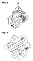
- Fig. 2 is a perspective view showing the machine tool displaced from the installation site to a different position;
- Fig. 3 is a plan view showing the machine tool that rotates when being moved from the installation site to the different position;
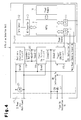
- Fig. 4 is a block diagram representing the configuration of the rotation detecting unit according to a first embodiment of the present invention;
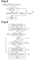
- Fig. 5 is a flowchart representing a rotation detecting unit procedure;
- Fig. 6 is a flowchart representing a communication procedure of the first embodiment;
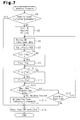
- Fig. 7 is a flowchart representing a detection procedure of the first embodiment;
- Fig. 8 is a flowchart representing a procedure performed when the power source of the body of the machine tool is turned on;
- Fig. 9 is a block diagram representing the configuration of a rotation detecting unit according to a second embodiment of the present invention;
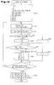
- Fig. 10 is a flowchart representing a detection procedure of the second embodiment;
- Fig. 11 is a flowchart representing a data updating procedure of the second embodiment;
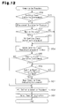
- Fig. 12 is a flowchart representing a communication procedure of the second embodiment; and
- Fig. 13 is a table representing data obtained through the detection procedure of the second embodiment.
- A displacement detector according to a first embodiment of the present invention will now be described with reference to Figs. 1 to 8.
- As shown in Figs. 1(A) to 1(C) and 2, a
machine tool 1, or a machine, has an installingportion 3 formed in a bottom portion of amachine body 2. Themachine tool 1 is installed horizontally at aninstallation site 4 through the installingportion 3. Acontrol panel 5 and apower port 6 are provided at a rear surface of themachine body 2. Acontrol panel 7 is arranged at a front surface of themachine body 2. Arotation detecting unit 8 is incorporated in thecontrol panel 5 as a determining device. Therotation detecting unit 8 performs a communication procedure with a displacementdetermination processing section 2a, which is provided in themachine body 2. In accordance with the communication procedure, it is determined whether themachine tool 1 has been displaced. - As illustrated in Figs. 3 and 4, the
rotation detecting unit 8 includes anMPU 9. Aflash memory 10 and an input-output device 11 are connected to theMPU 9. Agyro sensor 12 serving as an element is connected to theMPU 9 through an A/D converter 13. Thegyro sensor 12 detects rotation of themachine tool 1 caused by change of the orientation Y of themachine tool 1. Themachine tool 1 rotates about the vertical line V, which is perpendicular to the horizontal surface H at theinstallation site 4. Also, a power ON/OFF circuit 15 of apower supply circuit 14 is connected to theMPU 9. - When a
power cable 16 is connected to thepower port 6, amain power terminal 17 of therotation detecting unit 8 is connected to a non-illustrated main power source (a DC power source). When a non-illustrated body power switch of themachine tool 1 is turned on, the power is supplied from themain power terminal 17 to therotation detecting unit 8. Themain power terminal 17 is connected to apower switching circuit 18. Asecondary battery 20 is connected to thepower switching circuit 18. Thesecondary battery 20 is charged by themain power terminal 17 through abattery charging circuit 19. The power is supplied selectively from themain power terminal 17 and thesecondary battery 20 to the power ON/OFF circuit 15 through thepower switching circuit 18. - When receiving power from the
main power terminal 17, thepower switching circuit 18 supplies the power to the power ON/OFF circuit 15. Contrastingly, when receiving no power from themain power terminal 17, thepower switching circuit 18 supplies the power from thesecondary battery 20 to the power ON/OFF circuit 15. Arelay coil 21 is connected to themain power terminal 17. A normally closedcontact 22 is connected to the power ON/OFF circuit 15. The normally closedcontact 22 is selectively opened and closed through excitation or de-excitation of therelay coil 21. Based on a signal input from thegyro sensor 12 or the like, theMPU 9 performs different types of procedures based on the flowcharts of Figs. 5 to 8 and stores different types of data in theflash memory 10. - Such power supply to the
machine tool 1 is suspended if thepower cable 16 is removed from thepower port 6 or the breaker trips due to power outage caused by an earthquake or the like or themachine tool 1 is displaced from theinstallation site 4. The power supply to therotation detecting unit 8 is also stopped. At this stage, therelay coil 21 is de-excited and the normally closedcontact 22 is closed. In this state, an ON instruction Sa is sent to the power ON/OFF circuit 15. In response to the ON instruction Sa, the power is supplied from thesecondary battery 20 to theMPU 9 through thepower switching circuit 18 and the power ON/OFF circuit 15. - Referring to Figs. 4 and 5, when the power is supplied to the
MPU 9 to turn on theMPU 9, theMPU 9 executes a rotation detecting unit procedure. At this stage, theMPU 9 receives a main power checking signal Sb from themain power terminal 17 through the input-output device 11. In response to the main power checking signal Sb, theMPU 9 checks the state of the main power in step S1. After having determined that the main power is OFF, theMPU 9 performs step S2 to detect rotation data of themachine tool 1 and thus carries out the detection procedure represented in Fig. 7. Themachine tool 1 may be temporarily placed at a different position in transportation from theinstallation site 4 or installed in a different site. In these cases, thepower cable 16 is connected to thepower port 6 and the body power switch of themachine tool 1 is turned on so that the procedure represented in Fig. 8 is carried out. At this stage, theMPU 9 receives a power ON instruction Sc from the displacementdetermination processing section 2a of themachine body 2. In response to the power ON instruction Sc, theMPU 9 is turned on by the power supplied from themain power terminal 17. Then, based on the main power checking signal Sb provided by themain power terminal 17, theMPU 9 checks the state of the main power in step S1. After having determined that the main power is ON, theMPU 9 carries out step S3 to perform the communication procedure represented in Fig. 6. Data is transferred from therotation detecting unit 8 to themachine body 2 through the communication procedure. - When the
machine tool 1 is mounted on a transport vehicle for transportation to a different site, the orientation of themachine tool 1 is changed in a rotating direction about the vertical line V (see Figs. 2 and 3). In this state, thegyro sensor 12 detects rotation of themachine tool 1 caused by the change of the orientation Y of themachine tool 1. In step S4 of the detection procedure represented in Fig. 7, theMPU 9 determines whether themachine tool 1 has been displaced based on the condition signal that has been previously generated. If it is determined that themachine tool 1 has not been displaced, theMPU 9 carries out step S5. In step S5, theMPU 9 resets Val1, Max1, and Min1 to 0. Val1 represents displacement detection internal data, or a rotation angle. Max1 represents rotation data in terms of the forward direction of the rotating directions X shown in Fig. 3. Min1 represents rotation data in terms of the reverse direction of the rotating directions X shown in the drawing. In step S6, in accordance with the detection data obtained by thegyro sensor 12, theMPU 9 acquires the rotation data of themachine tool 1 as the rotation angle Δα. TheMPU 9 then performs step S7. - In step S7, the
MPU 9 determines Val1 using the following equation: Val1 = Val1 + Δα. Val1 is a rotation angle and set to 0° at the start of the detection. Val1 is used as internal data in accordance with which it is determined whether themachine tool 1 has been displaced. In step 88, theMPU 9 compares Val1 with Max1. If Val1 exceeds Max1, theMPU 9 updates Val1 to Max1 in step S9. If Val1 does not exceed Max1, theMPU 9 carries out step S10 without updating Val1 to Max1 and compares Val1 with Min1. If Val1 is less than Min1, theMPU 9 updates Val1 to Min1 in step S11. If Val1 is not less than Min1, theMPU 9 carries out step S12 without updating Val1 to Min1. - In step S12, the
MPU 9 compares the maximal rotation angle θm1 (see Fig. 3), or the difference between Max1 and Min1, with the predetermined value θr1 (the minimal value of the rotation angle in the rotation assumed to have been caused by displacement of the machine tool 1). If θm1 does not exceed θr1, theMPU 9 carries out step S13. In step S13, theMPU 9 checks the state of the main power source. If it is determined that the main power is OFF, it is likely that thepower cable 16 has been removed from thepower port 6 to displace themachine tool 1 from theinstallation site 4. In this case, theMPU 9 repeats step S6 and detects the rotation data of themachine tool 1 repeatedly. If θm1 exceeds θr1, theMPU 9 performs step S14 and sets a condition signal indicating that themachine tool 1 has been displaced. TheMPU 9 then carries out step S15. - If the
MPU 9 determines that themachine tool 1 has been displaced in step S4, theMPU 9 executes step S15 without detecting the rotation data of themachine tool 1, which has been described. TheMPU 9 performs step S15 also when theMPU 9 determines that the main power is ON in step S13. In step S15, theMPU 9 sends an OFF instruction Sd to the power ON/OFF circuit 15 (see Fig. 4). In response to the OFF instruction Sd, the power ON/OFF circuit 15 is turned off and the power supply to theMPU 9 is stopped. The detection procedure is thus ended. In the series of processing from step S4 to step S15, Max1 and Min1 are updated and the maximal rotation angle θm1 is detected. As long as the maximal rotation angle θm1 does not exceed the predetermined value θr1, the detection procedure is repeatedly carried out. However, once the maximal rotation angle θm1 exceeds the predetermined value θr1, the detection procedure is ended. - The communication procedure represented in Fig. 6 is performed if the
power cable 16 is reconnected to thepower port 6 and the body power switch of themachine tool 1 is turned on when themachine tool 1 is temporarily placed at a different position in transportation from theinstallation site 4 or installed in a different installation site. When the body power switch of themachine tool 1 is turned on, the displacementdetermination processing section 2a of themachine body 2 outputs the power ON instruction Sc. In response to the power ON instruction Sc, the power ON/OFF circuit 15 is turned on (see Fig. 4). This supplies the power from the main power source to theMPU 9 through thepower switching circuit 18. In step S16, a condition signal indicating whether themachine tool 1 has been displaced is sent from theMPU 9 to the displacementdetermination processing section 2a. In step S17, based on the condition signal, theMPU 9 determines whether themachine tool 1 has been displaced. If theMPU 9 determines that themachine tool 1 has been displaced, theMPU 9 performs step S18, or determines whether a condition reset instruction has been output from the displacementdetermination processing section 2a. If it is determined that the condition reset instruction has been output, theMPU 9 performs step S19. - In step S19, the
MPU 9 resets the condition signal indicating that themachine tool 1 has been displaced. TheMPU 9 then carries out step S20. If it is determined that the condition reset instruction has not been output, theMPU 9 repeatedly determines whether the condition reset instruction has been output. If theMPU 9 determines that themachine tool 1 has not been displaced based on the condition signal in step S17, theMPU 9 performs step S20. In step S20, theMPU 9 provides the OFF instruction Sd to the power ON/OFF circuit 15 (see Fig. 4). In response to the OFF instruction Sd, the power ON/OFF circuit 15 is turned off and the power supply from the main power source to theMPU 9 is suspended. The communication procedure is thus ended. In the series of processing from steps S16 to S20, after having sent the condition signal indicating whether themachine tool 1 has been displaced to the displacementdetermination processing section 2a, theMPU 9 resets the condition signal, which indicates whether themachine tool 1 has been displaced, based on the instruction provided by the displacementdetermination processing section 2a. TheMPU 9 then ends the communication procedure. - Finally, to allow the use of the
machine body 2, the procedure represented in Fig. 8 is performed. Specifically, when the body power switch of themachine tool 1 is turned on, the displacementdetermination processing section 2a sends the power ON instruction Sc to therotation detecting unit 8 in step S21. In response to the power ON instruction Sc, the power ON/OFF circuit 15 is activated and the power supply from the main power source to theMPU 9 is started. In step S22, the above-described communication procedure is carried out between therotation detecting unit 8 and the displacementdetermination processing section 2a. In step S23, the displacementdetermination processing section 2a determines whether themachine tool 1 has been displaced based on the condition signal. If the determination of step S23 is positive, the displacementdetermination processing section 2a informs the operator that themachine tool 1 has been displaced through an alarm or a display screen provided on thecontrol panel 7, and restricts the operation of themachine tool 1 in step S24. Such restriction is performed by, for example, prohibiting automatic activation of the machine. - In step S25, a canceling operation is performed to permit the
machine tool 1 to operate. The canceling operation is carried out through manipulation of a switch with a key or inputting of a password to turn on a cancel switch. In step S26, the displacementdetermination processing section 2a determines whether the canceling operation has been carried out correctly. If determination of step S26 is positive, the displacementdetermination processing section 2a performs step S27. If the determination is negative, the displacementdetermination processing section 2a repeats step S25, or determines whether the canceling operation has been performed correctly. - In step S27, the above-described communication procedure is performed between the
rotation detecting unit 8 and the displacementdetermination processing section 2a. At this stage, the displacementdetermination processing section 2a sends a condition reset instruction to therotation detecting unit 8. Step S28 is then performed. In step S28, the displacementdetermination processing section 2a stops displaying information on the display or stops generating the alarm on thecontrol panel 7. The displacementdetermination processing section 2a also cancels the restriction on the operation of themachine tool 1. The body power ON procedure is thus ended. If it is determined that themachine tool 1 has not been displaced in step S23, the displacementdetermination processing section 2a carries out step S28 without executing the above-described series of processing. The procedure is thus ended. - The first embodiment has the following advantages.
- (1) In transportation of the
machine tool 1 from the installation site, the orientation of themachine tool 1 is changed. In the first embodiment, thegyro sensor 12, or the element, is secured to themachine tool 1. Themachine tool 1 also has therotation detecting unit 8 serving as the determining device. Therotation detecting unit 8 determines whether themachine tool 1 has been displaced based on the rotation data obtained by thegyro sensor 12. In this manner, thegyro sensor 12 detects change of the orientation Y of themachine tool 1 as rotation of themachine tool 1. Therotation detecting unit 8 thus easily determines whether themachine tool 1 has been displaced. - (2) The rotation data of the
machine tool 1 represents the maximal rotation angle θm1 caused by the change of the orientation Y of themachine tool 1. Therotation detecting unit 8 determines whether themachine tool 1 has been displaced depending on whether the maximal rotation angle θm1 has exceeded the predetermined value θr1. That is, using the maximal rotation angle θm1, therotation detecting unit 8 easily determines whether themachine tool 1 has been displaced. - (3) The rotation data is obtained based on the rotation angle of the
machine tool 1 about the vertical line V perpendicular to the horizontal surface H of theinstallation site 4. Thus, with reference to the rotation angle of themachine tool 1 about the vertical line V, it is easily determined whether themachine tool 1 has been displaced. - (4) The
rotation detecting unit 8 has the power ON/OFF circuit 15. When the power supply to themachine tool 1 is blocked, therotation detecting unit 8 outputs the ON instruction Sa to the power ON/OFF circuit 15, and starts detecting the rotation angle of themachine tool 1. When the power supply to themachine tool 1 is resumed, therotation detecting unit 8 outputs an OFF instruction Sd to the power ON/OFF circuit 15 and ends detection of the rotation angle of themachine tool 1. This saves the power consumed in the detection of the rotation angle of themachine tool 1. In this case, it is defined that the condition of themachine tool 1 is changed if the power supply to themachine tool 1 has been cut or resumed. - (5) When the
rotation detecting unit 8 determines that themachine tool 1 has been displaced, therotation detecting unit 8 outputs an OFF instruction Sd to the power ON/OFF circuit 15 and ends the determination regarding displacement of themachine tool 1. In other words, such determination is suspended immediately after it is clearly determined that themachine tool 1 has been displaced. This saves the power consumed in the processing of the determination. - (6) If the
power cable 16 is removed from themachine tool 1 to cut the power supply to themachine tool 1, it is likely that themachine tool 1 is to be moved. Therotation detecting unit 8 thus provides the ON instruction Sa to the power ON/OFF circuit 15 and starts determining whether themachine tool 1 has been displaced. If thepower cable 16 is connected to themachine tool 1 to resume the power supply to themachine tool 1, it is likely that the displacement of themachine tool 1 has been completed. Therotation detecting unit 8 thus sends the OFF instruction Sd to the power ON/OFF circuit 15 and ends the determination regarding displacement of themachine tool 1. That is, such determination is suspended immediately after it is clearly determined that themachine tool 1 has been displaced. This saves the power consumed in the processing of such determination. - (7) As required by the displacement
determination processing section 2a, therotation detecting unit 8 provides information regarding displacement of themachine tool 1 to the displacementdetermination processing section 2a. When the body power switch of themachine tool 1 is turned on, the displacementdetermination processing section 2a outputs the power ON instruction Sc to the power ON/OFF circuit 15 and receives the information regarding displacement of themachine tool 1. If it is determined that themachine tool 1 has been displaced, the operation of themachine tool 1 is restricted. In this case, the information regarding the displacement of themachine tool 1 is communicated between therotation detecting unit 8 and themachine body 2. If themachine tool 1 has been displaced, the operation of themachine tool 1 is restricted regardless of whether such displacement has been brought about in an unauthorized manner. This effectively prevents unauthorized use of themachine tool 1. Themachine body 2 is permitted to operate only through the predetermined canceling operation. - Next, a displacement detector according to a second embodiment of the present invention will be explained with reference to Figs. 1 to 3, 5, 8, and 9 to 13. The explanation will focus on the differences between the first embodiment and the second embodiment. Figs. 9 and 12 correspond to Figs. 4 and 6, respectively. Figs. 10 and 11 each correspond to Fig. 7.
- As illustrated in Fig. 9, a
vibration sensor 23 is connected in series with the normally closedcontact 22 in therotation detecting unit 8. Thevibration sensor 23 is switched from OFF to ON when sensing vibration exceeding a predetermined level. When the body power switch of themachine tool 1 is turned off and the power supply to themain power terminal 17 is stopped, therelay coil 21 is de-excited and the normally closedcontact 22 is closed. In this state, if thevibration sensor 23 senses vibration exceeding the predetermined level and is switched on, an ON instruction Sa is sent to the power ON/OFF circuit 15. In response to the ON instruction Sa, theMPU 9 receives the power from thesecondary battery 20 through thepower switching circuit 18 and the power ON/OFF circuit 15. TheMPU 9 performs different procedures and stores different types of data in theflash memory 10 based on an input signal from thegyro sensor 12 or the like and in accordance with the flowcharts illustrated in Figs. 5, 8, and 10 to 12. - In the first embodiment, the communication procedure is carried out only after the
machine tool 1 is re-installed at a final installation site and the body power switch of themachine tool 1 is turned on. Themachine tool 1 may be temporarily placed at a plurality of positions in transportation from the initial installation site to the final installation site. The above-described detection procedure is performed continuously throughout such transportation. In the second embodiment, if themachine tool 1 is placed at a plurality of positions in the transportation from the original installation site to the final installation site and maintained at a certain position for a prolonged time, the detection procedure is not performed. The detection procedure is carried out only once each time themachine tool 1 is moved from one site to another. In other words, a first cycle of the detection procedure is performed when themachine tool 1 is located at a site between theoriginal installation site 4 and a first installation site. That is, an nth cycle of detection procedure is carried out when themachine tool 1 is located at a position between an (n-1)th installation site and an n th installation site. - Referring to Fig. 10, in step S29, the
MPU 9 resets n to n+1, i to 0, j to 0, the detected angle to 0, Max2 data (n) to 0, Min2 data (n) to 0, Val2 to 0, Max2 to 0, and Min2 to 0. TheMPU 9 then sets the detection start time (n), or a detection start point in time. The reference index i represents a rotation non-detected count and the reference index j represents a vibration non-detected count. Val2 represents internal data for detection of rotation, or a rotation angle. Max2 represents rotation data in terms of the forward direction of the rotating directions X. Min2 represents rotation data in terms of the reverse direction of the rotating directions X. The detection start time (n), the detection end time (n), Max2 data (n), Min2 data (n), and the detected angle (n) are history data obtained in the nth cycle of the detection procedure. In step S30, theMPU 9 acquires the rotation data of themachine tool 1 as the rotation angle Δα based on the detection data obtained by thegyro sensor 12. Subsequently, theMPU 9 carries out step S31, or performs the data updating procedure (steps S32 to S41) illustrated in Fig. 11. - As illustrated in Fig. 11, in step S32, the
MPU 9 obtains the detected angle from the equation: detected angle = detected angle + Δα. The detected angle is the rotation angle and set to 0° at the start of the detection. The detected angle is used in computation of the history data. In step S33, theMPU 9 compares the detected angle with the Max2 data (n). If the detected angle exceeds the Max2 data (n), theMPU 9 updates the detected angle to the Max2 data (n) in step S34. If the detected angle does not exceed the Max2 data (n), theMPU 9 performs step S35 without updating the detected angle to the Max2 data (n). In step S35, theMPU 9 compares the detected angle with the Min2 data (n). If the detected angle is less than the Min2 data (n), theMPU 9 updates the detected angle to the Min2 data (n) in step S36. If the detected angle is not less than the Min2 data (n), theMPU 9 performs step S37 without updating the detected angle to the Min2 data (n). In the series of processing from step S32 to step S36, the Max2 data (n) and the Min2 data (n) are updated each time the data of the corresponding cycle is updated. - In step S37, the
MPU 9 obtains Val2 using the equation: Val2 = Val2 + Δα. Val2 is the rotation angle and set to 0° in the latest determination that themachine tool 1 has been rotated. Val2 is used as internal data to determine whether themachine tool 1 has been rotated. In step S38, theMPU 9 compares Val2 with Max2. If Val2 exceeds Max2, theMPU 9 updates Val2 to Max2 in step S39. If Val2 does not exceed Max2, theMPU 9 performs step S40 without updating Val2 to Max2. In step S40, theMPU 9 compares Val2 with Min2. If Val2 is less than Min2, theMPU 9 updates Val2 to Min2 in step S41. If Val2 is not less than Min2, theMPU 9 performs step S42 without updating Val2 to Min2. In the series of processing from step S37 to step S41, Max2 data and Min2 data are updated each time the data of the corresponding cycle is updated. - In transportation of the
machine tool 1, thevibration sensor 23 is switched on when detecting vibration of themachine tool 1. Thevibration sensor 23 then outputs a vibration signal, which is input to theMPU 9. As illustrated in Fig. 10, in step S42, theMPU 9 determines whether themachine tool 1 has been vibrated based on the vibration signal. If such determination is positive, theMPU 9 performs step S43. In step S43, theMPU 9 resets j to 0 and carries out step S45. Contrastingly, if the determination is negative, theMPU 9 performs step S44. TheMPU 9 counts vibration non-detection in step S44 and then carries out step S45. In step S45, theMPU 9 compares the maximal rotation angle θm2, or the difference between Max2 and Min2, with a predetermined angle θr2. If θm2 exceeds θr2, theMPU 9 determines that themachine tool 1 has been rotated. Then, theMPU 9 resets i, Val2, Max2, and Min2 to 0 in step S46 and then performs step S48. Contrastingly, if θm2 does not exceed θr2, theMPU 9 carries out step S47 and counts the rotation non-detection. In step S48, theMPU 9 determines whether i and j both exceed the predetermined values. If such determination is positive, theMPU 9 performs step S49. The vibration non-detection count j and the rotation non-detection count i are the values that can be converted into time. Thus, if detection of vibration by thevibration sensor 23 lasts beyond a predetermined time and detection of rotation data by thegyro sensor 12 lasts beyond a predetermined time, theMPU 9 sets the detected angle (n) and the detection end time (n), or the detection end timing, and provides an OFF instruction Sd to the power ON/OFF circuit 15 in step S49. TheMPU 9 then ends the detection procedure. - If, in step S48, it is determined that the detection of vibration by the
vibration sensor 23 or the detection of rotation data by thegyro sensor 12 has ended within the predetermined time, or that at least one of i and j is less than the corresponding one of the predetermined values, theMPU 9 performs step S30 and repeats the above-described detection procedure. In the series of processing from steps S29 to S49, Max2 and Min2 are updated in each cycle of the detection procedure. In this series of processing, regardless of that themachine tool 1 is rotated or vibrated, the detection procedure is repeatedly performed as long as detection of the rotation data or the vibration of themachine tool 1 ends within the predetermined time. However, if such detection lasts beyond the predetermined time, the detection procedure is ended. - Like the first embodiment, the communication procedure represented in Fig. 12 is carried out when the body power switch of the
machine tool 1 is turned on. When the body power switch of themachine tool 1 is turned on, the displacementdetermination processing section 2a outputs a power ON instruction Sc. In response to the power ON instruction Sc, the power ON/OFF circuit 15 is turned on and the power is supplied from themain power terminal 17 to theMPU 9 through thepower switching circuit 18. In step S50, theMPU 9 determines whether themachine tool 1 has been displaced based on the condition signal that has been previously input. If it is determined that themachine tool 1 has been displaced, theMPU 9 carries out step S51. - Fig. 13 represents the history data representing Max2 data (n), Min2 data (n), and the detected angle for each of the first to nth cycles of the detection procedure, which starts at the detection start time and ends at the detection end time. Based on the data, the
MPU 9 determines the Σ detected angle obtained by sequentially adding the detected angles from the cycles of the detection procedure together, the absolute value converted from the Max2 data (n) obtained by adding the previous E detected angle to the current Max2 data (n), the absolute value converted from the Min2 data (n) obtained by adding the previous Σ detected angle to the current Min2 data (n), the final reference value corresponding to the maximum of the absolute value converted from the Max2 data (n) of each cycle, and the final reference value corresponding to the minimum of the absolute value converted from the Min2 data (n) of each cycle. Themachine tool 1 displays the history data on the display screen of thecontrol panel 7 or prints the data on paper. - Referring to Fig. 12, in step S51, the
MPU 9 performs the displacement determination procedure similar to the corresponding procedure of the first embodiment, using the history data. In the first embodiment, the displacement determination procedure is carried out in the series of the detection procedure illustrated in Fig. 7. However, in the second embodiment, the displacement determination procedure is performed in the communication procedure represented in Fig. 12. Max1 and Min1 in step S12 correspond to the final reference value of the absolute value converted from Max2 data (n) and the final reference value of the absolute value converted from Min2 data (n). If, in the current cycle of the detection procedure, the detection time from the detection start time to the detection end time is shorter than a predetermined time, it is indicated that rotation of themachine tool 1 has not been detected after the original detection of vibration of themachine tool 1. TheMPU 9 thus ignores the data from such detection. - If the
MPU 9 determines that themachine tool 1 has been displaced in step S52, theMPU 9 performs step S53. In step S53, theMPU 9 sets the condition signal indicating that themachine tool 1 has been displaced. TheMPU 9 then performs step S54. If theMPU 9 determines that themachine tool 1 has been displaced in step S50 or that themachine tool 1 has not been displaced in step S52, theMPU 9 carries out step S54. In step S54, the condition signal indicating whether themachine tool 1 has been displaced is sent from theMPU 9 to the displacementdetermination processing section 2a. Based on the condition signal, in step S55, theMPU 9 determines whether themachine tool 1 has been displaced. If theMPU 9 determines that themachine tool 1 has been displaced, theMPU 9 performs step S56. If, in step S56, theMPU 9 receives the condition reset instruction from the displacementdetermination processing section 2a, theMPU 9 carries out step S57. TheMPU 9 resets the condition signal indicating that themachine tool 1 has been displaced in step S57 and then performs step S58. If theMPU 9 determines that theMPU 9 has not received the condition reset instruction from the displacementdetermination processing section 2a in step S56, theMPU 9 repeatedly determines whether the condition reset instruction has been received. If it is determined that themachine tool 1 has not been displaced in step S55, theMPU 9 performs step S58. In step S58, theMPU 9 resets n to 0 and initializes the detection procedure. TheMPU 9 then performs step S59 in which theMPU 9 outputs an OFF instruction Sd to the power ON/OFF circuit 15. In response to the OFF instruction Sd, the power ON/OFF circuit 15 is turned off so that the power supply to theMPU 9 is blocked. The communication procedure is thus ended. - The second embodiment has the following advantages.
- (1) The history data regarding the rotation angle is memorized at a time point in the period from the detection start timing, at which detection of the rotation angle of the
machine tool 1 is started, to the detection end timing, at which such detection is ended. Based on the history data regarding the rotation angle, it is determined whether themachine tool 1 has been displaced. Such determination is thus carried out after detection of the rotation angle. Accordingly, it is easily determined whether themachine tool 1 has been displaced using the history data regarding the rotation angle detected at a time point in the period from the detection start timing to the detection end timing. - (2) The
vibration sensor 23, which detects vibration of themachine tool 1, is secured to themachine tool 1. With the power supply to themachine tool 1 blocked, the ON instruction Sa is output to the power ON/OFF circuit 15 in response to the vibration detection signal Se, which is obtained by thevibration sensor 23, and detection of the rotation angle of themachine tool 1 is started. That is, the determination whether themachine tool 1 has been displaced is started if the condition that vibration of themachine tool 1 caused through transportation of themachine tool 1 has been detected is satisfied. This saves the power necessary for detecting the rotation angle of themachine tool 1. In this case, it is determined that the condition of themachine tool 1 has been changed if themachine tool 1 has been vibrated and rotated in transportation of themachine tool 1. - (3) If the detection of vibration by the
vibration sensor 23 does not last beyond the predetermined time and detection of rotation data by thegyro sensor 12 does not last beyond the predetermined time, therotation detecting unit 8 provides the OFF instruction Sd to the power ON/OFF circuit 15 and ends the detection of the rotation angle of themachine tool 1. This saves the power consumed in the detection of the rotation angle of themachine tool 1. - The illustrated embodiments may be modified in the following forms.
- In each of the illustrated embodiments, the
gyro sensor 12 detects rotation of themachine tool 1 on the horizontal surface H. However, thegyro sensor 12 may detect rotation of themachine tool 1 on a vertical plane. Further, in addition to thegyro sensor 12, a two-axis acceleration sensor may be used to obtain an angular speed, or a geomagnetic sensor may be employed to detect rotation. Also, the present invention may be used to detect whether a measurement device or a laser oscillator has been displaced, other than themachine tool 1. - It is explicitly stated that all features disclosed in the description and/or the claims are intended to be disclosed separately and independently from each other for the purpose of original disclosure as well as for the purpose of restricting the claimed invention independent of the composition of the features in the embodiments and/or the claims. It is explicitly stated that all value ranges or indications of groups of entities disclose every possible intermediate value or intermediate entity for the purpose of original disclosure as well as for the purpose of restricting the claimed invention, in particular as limits of value ranges.
Claims (14)
- A displacement detector that determines whether a machine installed at a predetermined position has been displaced from the position, the detector being characterized by:an element that detects rotation of the machine caused by change of the orientation of the machine; anda determining device that determines whether the machine has been displaced based on rotation data of the machine obtained by the element.
- The displacement detector according to claim 1, being characterized in that the element is a gyro sensor.
- The displacement detector according to claim 1 or 2, being characterized in that the rotation data represents a maximal rotation angle obtained from the rotation angle of the machine caused by the change of the orientation of the machine, and
wherein the determining device determines whether the machine has been displaced based on the maximal rotation angle. - The displacement detector according to claim 1 or 2, being characterized in that the rotation data represents a rotation angle of the machine caused by the change of the orientation of the machine,
wherein the determining device includes a power ON/OFF circuit that selectively switches on and off power supply to the determining device, and
wherein the determining device has history data of the rotation angle recorded in a period from a detection start timing, at which an ON instruction is output to the power ON/OFF circuit and detection of the rotation angle is started, to a detection end timing, at which an OFF instruction is output to the power ON/OFF circuit and the detection of the rotation angle is ended. - The displacement detector according to claim 4, being characterized in that the determining device determines whether the machine has been displaced based on the history data.
- The displacement detector according to any one of claims 3 to 5, being characterized in that the rotation angle is a rotation angle about a vertical line perpendicular to a surface on which the machine is placed.
- The displacement detector according to any one of claims 1 to 6, being characterized in that the determining device has a power ON/OFF circuit that selectively switches on and off power supply to the determining device, and
wherein, based on change of the condition of the machine, the determining device provides an ON instruction to the power ON/OFF circuit and starts the detection of the rotation angle of the machine. - The displacement detector according to any one of claims 1 to 6, being characterized in that the determining device has a power ON/OFF circuit that selectively switches on and off power supply to the determining device, and
wherein, based on change of the condition of the machine, the determining device provides an OFF instruction to the power ON/OFF circuit and ends the detection of the rotation angle of the machine. - The displacement detector according to any one of claims 1, 2, 4 to 6, being characterized in that the machine has a vibration sensor that detects vibration of the machine,
wherein the determining device has a power ON/OFF circuit that selectively switches on and off power supply to the determining device, and
wherein, in response to a vibration detection signal obtained from the vibration sensor with the power supply to the machine blocked, the determining device provides an ON instruction to the power ON/OFF circuit and starts the detection of the rotation angle of the machine. - The displacement detector according to claim 9, being characterized in that, if the detection of the vibration of the machine does not last beyond a predetermined time and the detection of rotation of the machine does not last beyond a predetermined time, the determining device outputs an OFF instruction to the power ON/OFF circuit.
- The displacement detector according to any one of claims 1 to 3 and 6, being characterized in that the determining device has a power ON/OFF circuit that selectively switches on and off power supply to the determining device, and
wherein, if the machine has been displaced, the determining device outputs an OFF instruction to the power ON/OFF circuit and ends the determination whether the machine has been displaced. - The displacement detector according to any one of claims 1 to 3 and 6, being characterized in that the determining device has a power ON/OFF circuit that selectively switches on and off power supply to the determining device,
wherein, if the power supply to the machine is blocked, the determining device outputs an ON instruction to the power ON/OFF circuit and starts the determination whether the machine has been displaced, and
wherein, if the power supply to the machine is resumed and if the machine has been displaced with the power supply to the machine blocked, the determining device outputs an OFF instruction to the power ON/OFF circuit and ends the determination whether the machine has been displaced. - A machine having the displacement detector according to any one of claims 1 to 12, being characterized in that the machine has a displacement determination processing section that communicates information with the displacement detector,
wherein, in response to a demand from the displacement determination processing section, the determining device transmits information indicating whether the machine has been displaced to the displacement determination processing section,
wherein, when a body power switch of the machine is turned on, the displacement determination processing section outputs an ON instruction to the power ON/OFF circuit and receives the information indicating whether the machine has been displaced, and
wherein, if the machine has been displaced, the displacement determination processing section restricts operation of the machine. - The machine having the displacement detector according to claim 13, being characterized in that the displacement determination processing section permits operation of the machine after a predetermined canceling operation has been carried out.
Applications Claiming Priority (1)
| Application Number | Priority Date | Filing Date | Title |
|---|---|---|---|
| JP2006162037A JP4173513B2 (en) | 2006-06-12 | 2006-06-12 | Device relocation presence / absence detection device and device equipped with the device relocation presence / absence detection device |
Publications (1)
| Publication Number | Publication Date |
|---|---|
| EP1868052A2 true EP1868052A2 (en) | 2007-12-19 |
Family
ID=38473095
Family Applications (1)
| Application Number | Title | Priority Date | Filing Date |
|---|---|---|---|
| EP07011076A Withdrawn EP1868052A2 (en) | 2006-06-12 | 2007-06-05 | Displacement detector and machine having displacement detector |
Country Status (4)
| Country | Link |
|---|---|
| US (1) | US20080005604A1 (en) |
| EP (1) | EP1868052A2 (en) |
| JP (1) | JP4173513B2 (en) |
| CN (1) | CN101089554A (en) |
Families Citing this family (12)
| Publication number | Priority date | Publication date | Assignee | Title |
|---|---|---|---|---|
| JP5080091B2 (en) * | 2007-01-17 | 2012-11-21 | 株式会社ミツトヨ | Relocation detection device and installation type equipment |
| JP2009146376A (en) * | 2007-11-22 | 2009-07-02 | Fanuc Ltd | Numeral controller with transfer detection function |
| JP4945471B2 (en) * | 2008-02-06 | 2012-06-06 | ファナック株式会社 | Numerical control device with relocation prevention function |
| JP5101338B2 (en) * | 2008-02-28 | 2012-12-19 | スター精密株式会社 | Machine tool, unauthorized transfer notification device, and machine operation restriction method |
| JP2009271855A (en) * | 2008-05-09 | 2009-11-19 | Fanuc Ltd | Numerical control device having movement detection function |
| CN102200492B (en) * | 2010-02-26 | 2014-08-13 | 兄弟工业株式会社 | Detection system for mobile device |
| JP5504090B2 (en) | 2010-07-30 | 2014-05-28 | Dmg森精機株式会社 | Relocation detection method and relocation detection unit |
| JP5606247B2 (en) * | 2010-09-28 | 2014-10-15 | シチズンホールディングス株式会社 | Target position determination device |
| US8843346B2 (en) * | 2011-05-13 | 2014-09-23 | Amazon Technologies, Inc. | Using spatial information with device interaction |
| JP2015146140A (en) * | 2014-02-04 | 2015-08-13 | 古野電気株式会社 | Navigation computation device, theft notification device, theft notification system and theft detection method |
| JP2016151774A (en) | 2015-02-16 | 2016-08-22 | ファナック株式会社 | Transfer detection device for detecting transfer of device |
| JP6875347B2 (en) * | 2018-10-12 | 2021-05-26 | ファナック株式会社 | Thermal displacement compensator and numerical control device |
Family Cites Families (10)
| Publication number | Priority date | Publication date | Assignee | Title |
|---|---|---|---|---|
| JPS4835259A (en) * | 1971-09-10 | 1973-05-24 | ||
| JP2941953B2 (en) * | 1990-12-04 | 1999-08-30 | キヤノン株式会社 | Reference position detection method and rotation detector |
| US6205259B1 (en) * | 1992-04-09 | 2001-03-20 | Olympus Optical Co., Ltd. | Image processing apparatus |
| JPH08285753A (en) * | 1995-04-12 | 1996-11-01 | Bridgestone Corp | Thermal fatigue measuring method for viscoelastic body and servo flexometer |
| NZ336412A (en) * | 1998-06-26 | 2001-01-26 | Meinan Machinery Works | Centering log on veneer lathe by rotating log through one revolution to determine centres of each end |
| US7145305B2 (en) * | 2002-04-26 | 2006-12-05 | Honda Giken Kogyo Kabushiki Kaisha | System for estimating attitude of leg type moving robot itself |
| JP4744811B2 (en) * | 2004-02-25 | 2011-08-10 | 株式会社東芝 | Information processing apparatus and control method thereof |
| US8705022B2 (en) * | 2004-07-13 | 2014-04-22 | Trimble Navigation Limited | Navigation system using both GPS and laser reference |
| US7328125B2 (en) * | 2004-09-01 | 2008-02-05 | Canon Kabushiki Kaisha | Measuring method of cylindrical body |
| JP4532363B2 (en) * | 2005-07-07 | 2010-08-25 | 株式会社リコー | DIGITAL SPEED CONTROL DEVICE, DIGITAL MOTOR CONTROL DEVICE, PAPER CONVEYING DEVICE, DIGITAL SPEED CONTROL METHOD, PROGRAM FOR COMPUTER EXECUTING THE METHOD, COMPUTER READABLE RECORDING MEDIUM, AND IMAGE FORMING DEVICE |
-
2006
- 2006-06-12 JP JP2006162037A patent/JP4173513B2/en active Active
-
2007
- 2007-06-05 EP EP07011076A patent/EP1868052A2/en not_active Withdrawn
- 2007-06-11 CN CNA2007101119342A patent/CN101089554A/en active Pending
- 2007-06-11 US US11/761,057 patent/US20080005604A1/en not_active Abandoned
Also Published As
| Publication number | Publication date |
|---|---|
| CN101089554A (en) | 2007-12-19 |
| JP2007334395A (en) | 2007-12-27 |
| US20080005604A1 (en) | 2008-01-03 |
| JP4173513B2 (en) | 2008-10-29 |
Similar Documents
| Publication | Publication Date | Title |
|---|---|---|
| US20080005604A1 (en) | Displacement detector and machine having displacement detector | |
| US8760471B2 (en) | Information processing system, information processing method and program for synthesizing and displaying an image | |
| CN101674414B (en) | Image pickup apparatus | |
| EP3407157A1 (en) | Computing system implementing an algorithm for fusing data from inertial sensors, and method | |
| EP2464094B1 (en) | Means and method for assisting installation of monitoring camera | |
| KR20190087953A (en) | Indicators and indicating systems of working machines | |
| CN101346744A (en) | Method for configuring a monitoring device for monitoring a spatial area | |
| US20130231861A1 (en) | Terminal device, image displaying method and image displaying program executed by terminal device | |
| JP5101338B2 (en) | Machine tool, unauthorized transfer notification device, and machine operation restriction method | |
| JP6088049B2 (en) | Construction machinery | |
| EP4056319A1 (en) | Tool system, tool management method, and program | |
| KR20210022387A (en) | Hole location updating device and operating method of hole location updating device | |
| JP2012232663A (en) | Holder for mobile information processor and information processing system | |
| JP2013254251A (en) | Head-mounted display device, control method, and program | |
| KR102934888B1 (en) | Rotary switch apparatus for vehicle | |
| JP2006292522A (en) | Route guidance device | |
| JP2015204062A (en) | Drive recorder and acceleration correction program for drive recorder | |
| US7429930B2 (en) | Projector device with theft prevention function and theft preventing method | |
| KR20030069091A (en) | Electronic equipment, display control method, recording medium and program | |
| CN109154500A (en) | Laser leveling inspection | |
| JP2008129706A (en) | Startup control system of machine tool | |
| JP2009205317A (en) | Unauthorized move detection apparatus, machine tool and action restricting method | |
| JP5549924B2 (en) | Pedometer, pedometer mode determination method, computer program | |
| EP1275932B1 (en) | Program updating in a measuring device | |
| EP3478460B1 (en) | An industrial robot system comprising a dual arm robot |
Legal Events
| Date | Code | Title | Description |
|---|---|---|---|
| PUAI | Public reference made under article 153(3) epc to a published international application that has entered the european phase |
Free format text: ORIGINAL CODE: 0009012 |
|
| AK | Designated contracting states |
Kind code of ref document: A2 Designated state(s): AT BE BG CH CY CZ DE DK EE ES FI FR GB GR HU IE IS IT LI LT LU LV MC MT NL PL PT RO SE SI SK TR |
|
| AX | Request for extension of the european patent |
Extension state: AL BA HR MK YU |
|
| STAA | Information on the status of an ep patent application or granted ep patent |
Free format text: STATUS: THE APPLICATION HAS BEEN WITHDRAWN |
|
| 18W | Application withdrawn |
Effective date: 20090409 |