EP1867930A1 - Top plate structure of air conditioner for installation at high level - Google Patents
Top plate structure of air conditioner for installation at high level Download PDFInfo
- Publication number
- EP1867930A1 EP1867930A1 EP06731409A EP06731409A EP1867930A1 EP 1867930 A1 EP1867930 A1 EP 1867930A1 EP 06731409 A EP06731409 A EP 06731409A EP 06731409 A EP06731409 A EP 06731409A EP 1867930 A1 EP1867930 A1 EP 1867930A1
- Authority
- EP
- European Patent Office
- Prior art keywords
- top plate
- reinforcing ribs
- depth
- ribs
- reinforcing
- Prior art date
- Legal status (The legal status is an assumption and is not a legal conclusion. Google has not performed a legal analysis and makes no representation as to the accuracy of the status listed.)
- Withdrawn
Links
Images


Classifications
-
- F—MECHANICAL ENGINEERING; LIGHTING; HEATING; WEAPONS; BLASTING
- F24—HEATING; RANGES; VENTILATING
- F24F—AIR-CONDITIONING; AIR-HUMIDIFICATION; VENTILATION; USE OF AIR CURRENTS FOR SCREENING
- F24F13/00—Details common to, or for air-conditioning, air-humidification, ventilation or use of air currents for screening
- F24F13/08—Air-flow control members, e.g. louvres, grilles, flaps or guide plates
- F24F13/082—Grilles, registers or guards
-
- F—MECHANICAL ENGINEERING; LIGHTING; HEATING; WEAPONS; BLASTING
- F24—HEATING; RANGES; VENTILATING
- F24F—AIR-CONDITIONING; AIR-HUMIDIFICATION; VENTILATION; USE OF AIR CURRENTS FOR SCREENING
- F24F1/00—Room units for air-conditioning, e.g. separate or self-contained units or units receiving primary air from a central station
- F24F1/0007—Indoor units, e.g. fan coil units
- F24F1/0043—Indoor units, e.g. fan coil units characterised by mounting arrangements
- F24F1/0047—Indoor units, e.g. fan coil units characterised by mounting arrangements mounted in the ceiling or at the ceiling
-
- F—MECHANICAL ENGINEERING; LIGHTING; HEATING; WEAPONS; BLASTING
- F24—HEATING; RANGES; VENTILATING
- F24F—AIR-CONDITIONING; AIR-HUMIDIFICATION; VENTILATION; USE OF AIR CURRENTS FOR SCREENING
- F24F1/00—Room units for air-conditioning, e.g. separate or self-contained units or units receiving primary air from a central station
- F24F1/0007—Indoor units, e.g. fan coil units
- F24F1/0059—Indoor units, e.g. fan coil units characterised by heat exchangers
- F24F1/0063—Indoor units, e.g. fan coil units characterised by heat exchangers by the mounting or arrangement of the heat exchangers
Definitions
- the present invention relates to a top plate structure for a high location installation type air conditioner.
- An indoor unit for a high location installation type air conditioner such as an air conditioner concealed in or suspended from a ceiling of a house, includes, for example, a metal top plate forming a top surface of a cassette body casing.
- the air conditioner is concealed in the ceiling or suspended from a lower surface of the ceiling by suspending heavy objects such as a heat exchanger, fan, and fan motor from the top plate and then suspending the main body casing with suspension bolts or the like.
- Figs. 22 to 24 show a ceiling concealed air conditioner as one example of a high location installation type air conditioner.
- the air conditioner includes an air conditioner body 1, which is arranged in an upper part of an opening 7 formed in a ceiling C, and a decorative panel 2, which is attached to the body 1 to cover the opening 7.
- the body 1 has a cassette body casing 3, in which a generally annular heat exchanger 4 is arranged.
- a fan (impeller) 5 and a fan motor 9 are arranged in a central portion of the heat exchanger 4 in the body casing 3 in such a manner that an air inlet side of the fan 5 faces downward and an air outlet side of the fan 5 faces the side of the heat exchanger 4.
- a bell mouth 6 made of synthetic resin is arranged at the air inlet side of the fan 5 in the body casing 3.
- the fan 5 is formed by a centrifugal fan having a large number of blades 5b arranged between a hub 5b and a shroud 5c.
- a drain pan 8 is arranged below the heat exchanger 4.
- An air outlet passage 10 is formed around the periphery of the heat exchanger 4.
- the body casing 3 is generally hexagonal and includes a side wall 31 and a top plate 32.
- the side wall 31 is formed from a heat insulating material.
- the top plate 32 covers an upper portion of the side wall 31.
- the heat exchanger 4 includes a pair of opposing open ends.
- a tube plate 11 is arranged on each open end of the heat exchanger 4. The tube plates 11 are connected to each other by a predetermined partition plate 12.
- the top plate 32 of the body casing 3, the tube plates 11, the partition plate 12, and a switch box 13 attached to a lower surface of the bell mouth 6 are all formed from metal plates. As shown in Fig. 24, the top plate 32 and the switch box 13 are fixed to the top and bottom ends of the partition plate 12 by screws.
- the bell mouth 6 has a recessed portion 14 for accommodating the switch box 13.
- An opening 16 is formed in a top surface 14a of the recessed portion 14.
- a switch box joint 15 formed on a lower end portion of the partition plate 12 is arranged in the opening 16.
- Two mounting pieces 17, which project integrally from two sides of an upper end portion of the partition plate 12, are connected to the top plate 32.
- the mounting pieces 17 are fixed to the top plate 32 from under the top plate 32 by screws 18.
- Each mounting piece 19 which project integrally from two sides of a lower end portion of the partition plate 12, are connected to the lower ends of the two tube plates 11.
- a mounting piece 15 connected to the switch box 13 is welded and fixed to an intermediate position of the partition plate 12.
- Each mounting piece 19 is fixed to the corresponding tube plate 11 from under the tube plate 11 by a screw 20.
- Each mounting piece 15 includes an L-shaped base portion 15a and a mounting portion 15b.
- the base portion 15a is connected to the partition plate 12.
- the mounting portion 15b extends downward from a distal end of the base portion 15a and is formed integrally with the base portion 15a. In a state in which the mounting portion 15b is arranged in the recessed portion 14 through the opening 16, each mounting piece 15 is fixed to a top surface 13a of the switch box 13 by screws 21.
- the air conditioner includes a drain pump 22, a float switch 23, a drain pump accommodation portion 24 in which the drain pump 22 is arranged, a partition plate 25 partitioning the drain pump accommodation portion 24, and a lid 26 of the switch box 13.
- the top plate 32 is hexagonal and shaped in correspondence with the body casing 3 of the air conditioner body 1.
- the top plate 32 has a peripheral portion along which a hook-shaped rim portion 32c is formed.
- the rim portion 32c is for fitting the top plate 32 and a peripheral portion at the upper end of the body casing 3 with each other.
- the top plate 32 has a plurality of main reinforcing ribs 32a extending radially from a central portion 33 of the top plate 32 at which the fan 5 and the fan motor 9 are supported to a peripheral portion of the top plate 32 at which the generally annular heat exchanger 4 is supported.
- the main reinforcing ribs 32a are recessed in a downward direction.
- Each main reinforcing rib 32a has a predetermined width and a predetermined depth.
- Each main reinforcing rib 32a includes an outer part defining a heat exchanger support portion having a step portion 32b with a smaller recess depth.
- the main reinforcing ribs 32a enable the top plate 32 to have the required levels of basic rigidity, strength, deflection, and vibration characteristics.
- the interval between the main reinforcing ribs 32a increases toward the peripheral portion of the top plate 32. This made result in the top plate 32 having insufficient rigidity and strength. Accordingly, a plurality of sub-reinforcing ribs 34 are arranged between the main reinforcing ribs 32a as shown in Fig. 24. The shape and dimensions of the sub-reinforcing ribs 34 are determined in accordance with the load that can be assumed to be applied to the top plate 32.
- This structure is designed to reduce the static deflection of the top plate 32 to or below a fixed value and maintains the primary natural vibration frequency of the top plate 32 to or above a fixed value to avoid resonance caused by rotation of the fan motor 9.
- the top plate 32 further includes a reinforcing rib 33a, which is triangular when viewed from above, arranged in at the central portion 33 where the fan 5 and the fan motor 9 are supported. This improves the rigidity, strength, deflection, and vibration characteristics of the supporting portion of the fan 5 and the fan motor 9 (refer to patent document 1).
- the supporting portion of the fan 5 and the fan motor 9 includes a circular groove formed in each corner of the reinforcing rib 33a.
- the reinforcing rib 33a includes three fan motor mounting portions a, b, and c formed in central portions of the circular grooves.
- the fan motor 9 is suspended from and fixed to the fan motor mounting portions a, b, and c by mount members 11, which absorb vibrations, and a mounting bracket 9b. This rotatably supports the fan 5 by means of a motor shaft 9a.
- the cost of the air conditioner is required to be reduced from various perspectives.
- the cost of the top plate 32 used in the air conditioner is also required to be reduced.
- the plate thickness of the entire the top plate 32 (for example, 0.8 mm) may be reduced (for example, to about 0.7 to 0.6 mm) to reduce material cost and facilitate formation of the ribs etc.
- reduction in the plate width would lower the rigidity and strength of the top plate 32 and require measures for suppressing vibrations of the top plate 32 generated when driving of the fan.
- a top plate formed with a lower plate thickness than the existing plate decreases material cost and is easily deformed. This enables the force that is required for pressing and forming the top plate and facilitates formation of the top plate.
- a thinner top plate includes the radial reinforcing ribs of the above-described conventional structure, the amount of static deflection increases and the primary natural vibration frequency resulting from rotation of the fan motor 9 decreases. As a result, the top plate would not satisfy the design standards.
- a first aspect of the present invention provides a top plate structure for an air conditioner including a body casing for accommodating a fan, a fan motor, and a heat exchanger.
- a top plate forming a top surface of the body casing suspends the fan, the fan motor, and the heat exchanger.
- the top plate has a plurality of radial reinforcing ribs extending from a central portion of the top plate at which the fan motor is supported to a peripheral portion of the top plate at which the heat exchanger is supported.
- the plurality of reinforcing ribs include a reinforcing rib protruding from a front surface of the top plate and a reinforcing rib protruding from a rear surface of the top plate.
- the top plate is provided with the required levels of rigidity, strength, deflection, and vibration characteristics.
- the structure in which the reinforcing rib portions protrude in two directions from the front surface and the rear surface of the top plate substantially doubles the vertical wall height dimensions of the top plate between the front and rear surfaces. This greatly improves rigidity of the top plate against deflection. As a result, the plate thickness of the top plate can be decreased, the formation of the top plate is facilitated, and the manufacturing cost of the top plate is decreased.
- the reinforcing rib protruding from the front surface of the top plate and the reinforcing rib protruding from the rear surface are alternately arranged in a circumferential direction of the top plate. This improves the supporting rigidity of the top plate in a balanced manner throughout the entire top plate and uniformly reduces the maximum deflection amount of the top plate.
- the plurality of reinforcing ribs include a plurality of long main reinforcing ribs and a plurality of short sub-reinforcing ribs arranged between the main reinforcing ribs, and the main reinforcing ribs protrude from one of a front surface and a rear surface of the top plate and the sub-reinforcing ribs protrude from the other one of the front surface and the rear surface of the top plate.
- This improves the supporting rigidity of the top plate in a balanced manner throughout the entire top plate and uniformly reduces the maximum deflection amount of the top plate.
- the reinforcing ribs each have a depth that changes in a longitudinal direction of the reinforcing rib, and the depth at two end portions of each reinforcing rib is less than the depth between the two end portions. This further effectively reduces the maximum deflection amount of the top plate and further improves the resonance rotation speed of the top plate. As a result, further reduction in the cost of the top plate resulting from lower material cost can be expected.
- the top plate has a plate thickness that is set in a range of 0.6 to 0.7 mm.
- the material cost is lowered and press formation is facilitated as the plate thickness of the top plate 32 decreases.
- the strength and rigidity of the top plate 32 decreases and the deflection characteristics and vibration characteristics of the top plate 32 deteriorate as the plate thickness of the top plate 32 decreases.
- the sub-reinforcing ribs are effective in compensating for such a situation.
- the top plate 32 would still require a certain plate thickness.
- the plate thickness of the top plate 32 may be reduced to a range of 0.6 to 0.7 mm, which is less than the plate thickness of 0.8 mm of the conventional top plate. This also ensures sufficiently support rigidity for the top plate 32. Accordingly, the cost of the top plate is effectively reduced through material cost reduction.
- this range of plate thickness (0.6 mm to 0.7 mm) is the optimal range of plate thickness that reduces material cost, facilitates formation, and ensures the required quality performance in view of the relationship between the plate thickness of the conventional top plate and the reinforcing effect of the reinforcing ribs.
- the reinforcing ribs each have a depth of 8.0 to 10.0 mm.
- the design standard requires the maximum deflection of the top plate to be reduced to 1.31 mm or less and the resonance rotation speed of the top plate to be maintained at 742.0 rpm or higher.
- the appropriate depth of each reinforcing rib is 8.0 to 10.0 mm.
- Figs. 1 to 6 show a top plate structure for a high location installation type air conditioner according to a first embodiment of the present invention.
- a top plate 32 of the first embodiment is optimal for application to a body casing 3 of a ceiling concealed air conditioner (indoor unit) that is substantially the same as that of the conventional example described with reference to Figs. 22 to 24.
- the top plate 32 has a plate thickness D 4 set at 0.7 mm, which is smaller than a thickness of 0.8 mm of a conventional top plate.
- the top plate 32 is hexagonal and shaped in correspondence with the cassette body casing 3 of the air conditioner.
- the top plate 32 has a peripheral portion along which a hook-shaped rim portion 32c is formed to be fitted with the peripheral portion of an upper end of the body casing 3.
- the top plate 32 has a central portion 33 supporting a fan 5 and a fan motor 9 and a peripheral portion supporting a generally annular heat exchanger 4.
- the top plate 32 includes two different kinds of reinforcing ribs, namely, a plurality of radially extending reinforcing ribs 32a and a plurality of radially extending reinforcing ribs 32a'.
- the reinforcing ribs 32a and 32a' extend from the central portion 33 to the peripheral portion of the top plate 32.
- the reinforcing ribs 32a and 32a' protrude alternately from front and rear surfaces of the top plate 32.
- the reinforcing ribs 32a and 32a' each have an inverted trapezoidal cross-sectional shape and each have a bottom surface width W 1 , a top width W 2 , a depth D 2 , and an inclination angle ⁇ 2 .
- the step portion 32b of each reinforcing rib 32a is recessed downward with a depth D 3 smaller than the depth D 2 by a predetermined dimension.
- the top plate 32 further has a reinforcing rib 33a having a depth D 1 arranged on a supporting portion for the fan 5 and the fan motor 9 in the central portion 33.
- the depth D 1 is equal to the depth D 2 .
- the reinforcing rib 33a extends between five fan motor support portions a to e, which enable supporting at three points or four points, and is in contact with the fan motor support portions a to e.
- the reinforcing rib 33a effectively improves rigidity, strength, deflection, and vibration characteristics of the supporting portion of the fan 5 and the fan motor 9.
- heavy components including the heat exchanger 4, the fan 5, and the fan motor 9 are attached to the top plate 32 in the same manner as in the conventional structure.
- the structure of the present embodiment includes the radial reinforcing ribs 32a' and 32a extending from the central portion 33 of the top plate 32 on which the fan motor 9 is supported to the peripheral portion of the top plate 32 on which the heat exchanger 4 is supported.
- the reinforcing ribs 32a' protrude from the front surface of the top plate 32, and the reinforcing ribs 32a protrude from the rear surface of the top plate 32.
- the top plate 32 may be improved to the required levels for rigidity, strength, deflection characteristics, vibration characteristics, and the like.
- the structure in which the reinforcing rib portions protrude both from the front surface and the rear surface of the top plate 32 substantially doubles the vertical wall height dimensions of the top plate 32 between its front and rear surfaces and greatly improves rigidity of the top plate 32 against deflection. This structure reduces the plate thickness of the top plate 32 and facilitates the formation of the top plate 32, thereby reducing the manufacturing cost of the top plate 32.
- reinforcing ribs 32a' protruding from the front surface of the top plate 32 and the reinforcing ribs 32a protruding from the rear surface of the top plate 32 are arranged alternately in the circumferential direction. This structure improves the supporting rigidity of the top plate 32 in a balanced manner throughout the entire top plate 32 and uniformly reduces the maximum deflection amount of the top plate 32 throughout the entire top plate 32.
- the reinforcing ribs 32a' and 32a are each formed to have a depth h that changes so as to decrease as the two end portions in the longitudinal direction (radial direction) become closer and increase as the portion between the two end portions become closer.
- h1 represents the depth of the two end portions of each reinforcing rib
- h2 represents the depth of the intermediate portion between the two end portions
- each of the reinforcing ribs 32a and 32a' changes in the longitudinal direction to have a smaller depth in the two end portions and a larger depth in the intermediate portion between the two end portions. This further effectively reduces the maximum deflection amount of the top plate 32, improves the resonance rotation speed of the top plate 32, and reduces the cost of the top plate 32 by lowering material cost.
- the plate thickness of the top plate 32 is set in the range of 0.6 to 0.7 mm.
- the material cost for the top plate 32 decreases and press formation of the top plate 32 is facilitated as the plate thickness of the top plate 32 decreases.
- the strength and rigidity of the top plate 32 decreases and the deflection and vibration characteristics of the top plate 32 deteriorate as the plate thickness of the top plate 32 decreases.
- the reinforcing ribs 32a' and 32a having the above-described structure effectively prevent such characteristics of the top plate 32 from deteriorating.
- the top plate 32 still needs to have a certain level of plate thickness.
- top plate structure using the reinforcing ribs 32a' and 32a described above enables the plat thickness of the top plate 32 to be reduced to a range of 0.6 to 0.7 mm.
- the structure enables the top plate 32 with such reduced plate thicknesses to have sufficiently high supporting rigidity and stable vibration characteristics. As a result, the cost of the top plate 32 can be expected to be effectively decreased by the lowered material cost.
- This range of plate thickness is optimum for lowering the material cost of the top plate 32, facilitating formation of the top plate 32, and ensuring the required quality performance.
- This plate thickness range is determined based on the relationship between the plate thickness of the conventional top plate and the reinforcing effect of the reinforcing ribs described above.
- the top plate structure for the high location installation type air conditioner enables the top plate to have stable supporting rigidity, supporting strength, and low-noise performance while reducing the thickness of the top plate and reducing the cost of the top plate.
- top plates that differ from one another in the quantity of reinforcing ribs shown in Fig. 7 (six ribs), Fig. 9 (eight ribs), Fig. 12 (ten ribs), and Fig. 15 (12 ribs) irrespective of the protruding direction of the ribs are used as basic models.
- a top plate having ribs 32a arranged only on one side and a top plate having ribs 32a' and 32a arranged on two sides were prepared using each of the basic models of Fig. 9 (eight ribs) and Fig. 12 (ten ribs).
- a top plate having ribs 32a arranged only on one side was prepared using each of the basic models of Fig. 7 (six ribs) and Fig.
- top plates 32A to 32F of test samples 1 to 6 were prepared in total. All the top plates 32A to 32F have the plate thickness of 0.7 mm. Refer to Table 1 for the specifications of the top plates 32A and 32F.
- the root R (mm) indicates the radius of an arc linking basal ends of a pair of adjacent reinforcing ribs.
- Table 1 Sample No. 1 2 3 4 5 6 Quantity 6 8 8 10 10 12 Width W (mm) 60.0 Length L (mm) 696.0 Root R (mm) 81.0 39.0 39.0 20.0 20.0 9.5 Depth h (mm) One Side 9.5 6.0 - 9.5 - 9.5 Two Sides - - 8.0 - 9.5 -
- the first top plate 32A includes six reinforcing ribs 32a that are arranged at equal intervals of 60 degrees in the circumferential direction.
- the dimension (length) between the two distal ends of two opposing reinforcing ribs 32a arranged at an interval of 180 degrees is 696.0 mm.
- Each reinforcing rib 32a has a groove width W of 60.0 mm. The reinforcing ribs 32a protrude from only either one of the front surface and the rear surface of the top plate 32A (refer to Fig. 8).
- the second top plate 32B includes eight reinforcing ribs 32a that are arranged at equal intervals of 45 degrees in the circumferential direction.
- the dimension (length) between the two distal ends of two opposing reinforcing ribs 32a arranged at an interval of 180 degrees is 696.0 mm.
- Each reinforcing rib 32a has a groove width W of 60.0 mm. The reinforcing ribs 32a protrude from only either one of the front surface and the rear surface of the top plate 32B (refer to Fig. 10).
- the third top plate 32C includes eight reinforcing ribs 32a' and 32a that are arranged at equal intervals of 45 degrees in the circumferential direction.
- the dimension (length) between the two distal ends of two opposing reinforcing ribs 32a' and 32a arranged at an interval of 180 degrees is 696.0 mm.
- Each of the reinforcing ribs 32a' and 32a has a groove width W of 60.0 mm.
- the reinforcing ribs 32a' and 32a protrude alternately from both the front surface and the rear surface of the top plate 32C (refer to Fig. 11).
- the fourth top plate 32D includes ten reinforcing ribs 32a that are arranged at equal intervals of 36 degrees in the circumferential direction.
- the dimension (length) between the two distal ends of two opposing reinforcing ribs 32a' and 32a arranged at an interval of 180 degrees is 696.0 mm.
- Each reinforcing rib 32a has a groove width W of 60.0 mm. The reinforcing ribs 32a protrude from only either one of the front surface and the rear surface of the top plate 32D (refer to Fig. 13).
- the fifth top plate 32E includes ten reinforcing ribs 32a' and 32a that are arranged at equal intervals of 36 degrees in the circumferential direction.
- the dimension (length) between the two distal ends of two opposing reinforcing ribs 32a' and 32a arranged at an interval of 180 degrees is 696.0 mm.
- Each of the reinforcing ribs 32a' and 32a has a groove width W of 60.0 mm.
- the reinforcing ribs 32a' and 32a protrude alternately from both the front surface and the rear surface of the top plate 32E (refer to Fig. 14).
- the sixth top plate 32F includes twelve reinforcing ribs 32a that are arranged at equal intervals of 30 degrees in the circumferential direction.
- the dimension (length) between the two distal ends of two opposing reinforcing ribs 32a arranged at an interval of 180 degrees is 696.0 mm.
- Each reinforcing rib 32a has a groove width W of 60.0 mm. The reinforcing ribs 32a protrude from only either one of the front surface and the rear surface of the top plate 32F (refer to Fig. 16).
- each top plate 32 having the radial reinforcing ribs 32a protruding from only one side are shown in Table 2 and the graphs in Figs. 17 and 18.
- the reinforcing ribs 32a all have the same width W, length L, and depth h.
- Table 2 Rib Specifications Maximum Deflection (mm) Resonance Rotation Speed Quantity Depth (mm) Primary Secondary 6 9.5 1.60 784.0 990.0 8 9.5 1.35 907.0 990.0 10 9.5 1.32 914.0 940.0 12 9.5 1.41 890.0 917.0
- the overall static characteristics and dynamic characteristics of the top plate 32 including eight reinforcing ribs 32a and the top plate 32 including ten reinforcing ribs 32a are superior to the static and dynamic characteristics of the top plate 32 including six reinforcing ribs 32a and the top plate 32 including twelve reinforcing ribs 32a.
- the top plate 32 including eight reinforcing ribs 32a and the top plate 32 including ten reinforcing ribs 32a have substantially the same deflection amount (1.35/1.32 mm) and substantially the same primary resonance rotation speed (907.0/914.0 rpm). However, the top plate 32 including eight ribs has the secondary resonance rotation speed of 990.0 rpm, and the top plate 32 including ten ribs has the secondary resonance rotation speed of 940.0 rpm, which is 5.0% lower than the secondary resonance rotation speed of the top plate 32 including eight ribs.
- the top plate 32 including eight reinforcing ribs 32a is assumed to have the best static and dynamic characteristics.
- Table 3 and the graphs in Figs. 19 and 20 show that the top plates 32 having the double-side rib arrangement have better static and dynamic characteristics than the top plates 32 having the single-side rib arrangement.
- the inventors of the present application further researched changes in the maximum deflection amount and the resonance rotation speed resulting from different rib depths of the top plate 32 when using a plurality of parallel ribs in lieu of the radial ribs described above. More specifically, the inventors measured the maximum deflection amount and the resonance rotation speed of the top plates 32 having a single-side rib arrangement of parallel ribs and a double-side rib arrangement of parallel ribs.
- the measurement results show that the maximum deflection amount and the resonance rotation speed of the top plate 32 are significantly affected by the rib depth when the depth of the parallel ribs is 2.0 to 6.0 mm and relatively shallow. This indicates that small differences in the rib depth greatly change the maximum deflection amount and the resonance rotation speed of the top plates 32 when the rib depth is relatively small. Thus, robustness of the static and dynamic characteristics of the top plates 32 with respect to the rib depth is low when the rib depth is relatively small.
- the influence of the rib depth on the maximum deflection amount and the resonance rotation speed of the top plates 32 is limited. This indicates that differences in the rib depth only slightly change the maximum deflection amount and the resonance rotation speed of the top plate 32 when the rib depth is large. Thus, robustness of the static and dynamic characteristics of the top plates 32 with respect to the rib depth is high when the rib depth is large.
- the design standard requires that the maximum deflection amount of the top plate 32 be suppressed at 1.31 mm or less and that the resonance rotation speed be maintained at 742.0 rpm or higher.
- the rib depth is preferably 8.0 to 10.0 mm to satisfy the design standard while maintaining robustness of the static and dynamic characteristics of the top plate 32 with respect to the rib depth.
- Fig. 21 shows a top plate structure for a high location installation type air conditioner according to a second embodiment of the present invention.
- a top plate 32 of the second embodiment is also optimal for application to a body casing 3 of a ceiling concealed air conditioner (indoor unit) that is substantially the same as that in the conventional example shown in Figs. 22 to 24.
- the top plate 32 is formed to have a plate thickness of about 0.7 mm, which is smaller than the thickness of 0.8 mm of the conventional top plate.
- the top plate 32 is hexagonal and shaped in correspondence with the cassette body casing 3 of the air conditioner shown in Figs. 22 to 24.
- the top plate 32 has a peripheral portion along which a hook-shaped rim portion 32c is formed to be fitted with the peripheral portion of an upper end of the body casing 3.
- a fan 5 and a fan motor 9 identical to the structures shown in Figs. 22 to 24 are supported on a central portion 33 of the top plate 32.
- a generally annular heat exchanger 4 is supported on the peripheral portion of the top plate 32.
- the top plate 32 includes a plurality of radially extending main reinforcing ribs 32a extending from the central portion 33 to the peripheral portion of the top plate 32.
- the main reinforcing ribs 32a protrude from a rear surface of the top plate 32.
- the main reinforcing ribs 32a each have an inverted trapezoidal cross-section and each have a bottom surface width W 1 , a top width W 2 , a depth D 2 , and an inclination angle ⁇ 2 .
- a heat exchanger support portion located on the outer side of each main reinforcing rib 32a has a step portion 32b.
- the step portion 32b is recessed downward with a depth D3 that is smaller than the depth D 2 by a predetermined dimension (the dimension not shown).
- the top plate 32 further has a reinforcing rib 33a having a depth D 1 arranged on a supporting portion for the fan 5 and the fan motor 9 in the central portion 33.
- the depth D 1 is equal to the depth D 2 .
- the reinforcing rib 33a extends between five fan motor support portions a to e, which enable supporting at three points or four points, and is in contact with the fan motor support portions a to e.
- This structure effectively improves basic rigidity, strength, deflection, and vibration characteristics of the supporting portion of the fan 5 and the fan motor 9.
- the interval between the main reinforcing ribs 32a in the peripheral portion of the top plate 32 is large.
- the peripheral portion of the top plate 32 may have insufficient rigidity, strength, etc.
- the top plate 32 further has a plurality of sub-reinforcing ribs 34 arranged between the main reinforcing ribs 32a as shown in the drawing.
- the shape and dimensions of the sub-reinforcing ribs are determined in accordance with the load assumed to be applied to the top plate 32.
- the main reinforcing ribs 32a protrude from the rear surface of the top plate 32
- the sub-reinforcing ribs 34 protrude from the surface opposite to the surface from which the main reinforcing ribs 32a protrude.
- This structure reduces the static deflection of the top plate 32 to a fixed value or lower and maintains the primary natural vibration frequency of the top plate 32 at a fixed value or greater to avoid resonance caused by rotation of the fan motor 9.
- Heavy components including the heat exchanger 4, the fan 5, and the fan motor 9 are attached to the top plate 32 having the above-described structure in the same manner as in the conventional structure.
- the plurality of reinforcing ribs in the second embodiment include the long main reinforcing ribs 32a and the short sub-reinforcing ribs 34 arranged between the long reinforcing ribs 32a, and the main reinforcing ribs 32a protrude from either one of the front surface and the rear surface of the top plate 32, and the sub-reinforcing ribs 34 protrude from the surface opposite the surface from which the main reinforcing ribs 32a protrude.
- the structure having the sub-reinforcing ribs 32a also has the same advantages as described in the first embodiment. This structure improves the supporting rigidity of the top plate 32 in a balanced manner throughout the entire top plate 32 and uniformly reduces the maximum deflection amount of the top plate 32.
- This structure also reduces the sufficient plate thickness of the top plate 32 to 0.6 to 0.7 mm.
Abstract
A high location installation type air conditioner includes a body casing (3) for accommodating a fan (5), a fan motor (9), and a heat exchanger (4), and a top plate (32) forming a top surface of the body casing (3) for suspending the fan (5), the fan motor (9), and the heat exchanger (4). The top plate (32) includes a plurality of radial reinforcing ribs extending from a central portion of the top plate (32) at which the fan motor (9) is supported to a peripheral portion of the top plate (32) at which the heat exchanger (4) is supported. The plurality of reinforcing ribs include a reinforcing rib (32a') protruding from a front surface of the top plate (32) and a reinforcing rib (32a) protruding from a rear surface of the top plate (32) to improve rigidity of the top plate (32).
Description
- The present invention relates to a top plate structure for a high location installation type air conditioner.
- An indoor unit for a high location installation type air conditioner, such as an air conditioner concealed in or suspended from a ceiling of a house, includes, for example, a metal top plate forming a top surface of a cassette body casing. The air conditioner is concealed in the ceiling or suspended from a lower surface of the ceiling by suspending heavy objects such as a heat exchanger, fan, and fan motor from the top plate and then suspending the main body casing with suspension bolts or the like.
- Figs. 22 to 24 show a ceiling concealed air conditioner as one example of a high location installation type air conditioner. As shown in Figs. 22 to 24, the air conditioner includes an air conditioner body 1, which is arranged in an upper part of an opening 7 formed in a ceiling C, and a
decorative panel 2, which is attached to the body 1 to cover the opening 7. The body 1 has acassette body casing 3, in which a generallyannular heat exchanger 4 is arranged. A fan (impeller) 5 and afan motor 9 are arranged in a central portion of theheat exchanger 4 in thebody casing 3 in such a manner that an air inlet side of the fan 5 faces downward and an air outlet side of the fan 5 faces the side of theheat exchanger 4. Abell mouth 6 made of synthetic resin is arranged at the air inlet side of the fan 5 in thebody casing 3. - The fan 5 is formed by a centrifugal fan having a large number of
blades 5b arranged between ahub 5b and ashroud 5c. Adrain pan 8 is arranged below theheat exchanger 4. Anair outlet passage 10 is formed around the periphery of theheat exchanger 4. - The
body casing 3 is generally hexagonal and includes aside wall 31 and atop plate 32. Theside wall 31 is formed from a heat insulating material. Thetop plate 32 covers an upper portion of theside wall 31. Theheat exchanger 4 includes a pair of opposing open ends. Atube plate 11 is arranged on each open end of theheat exchanger 4. Thetube plates 11 are connected to each other by apredetermined partition plate 12. - The
top plate 32 of thebody casing 3, thetube plates 11, thepartition plate 12, and aswitch box 13 attached to a lower surface of thebell mouth 6 are all formed from metal plates. As shown in Fig. 24, thetop plate 32 and theswitch box 13 are fixed to the top and bottom ends of thepartition plate 12 by screws. - The
bell mouth 6 has arecessed portion 14 for accommodating theswitch box 13. Anopening 16 is formed in atop surface 14a of therecessed portion 14. Aswitch box joint 15 formed on a lower end portion of thepartition plate 12 is arranged in theopening 16. Twomounting pieces 17, which project integrally from two sides of an upper end portion of thepartition plate 12, are connected to thetop plate 32. Themounting pieces 17 are fixed to thetop plate 32 from under thetop plate 32 byscrews 18. - Two
mounting pieces 19, which project integrally from two sides of a lower end portion of thepartition plate 12, are connected to the lower ends of the twotube plates 11. Amounting piece 15 connected to theswitch box 13 is welded and fixed to an intermediate position of thepartition plate 12. Eachmounting piece 19 is fixed to thecorresponding tube plate 11 from under thetube plate 11 by ascrew 20. Eachmounting piece 15 includes an L-shaped base portion 15a and amounting portion 15b. Thebase portion 15a is connected to thepartition plate 12. Themounting portion 15b extends downward from a distal end of thebase portion 15a and is formed integrally with thebase portion 15a. In a state in which themounting portion 15b is arranged in therecessed portion 14 through the opening 16, eachmounting piece 15 is fixed to atop surface 13a of theswitch box 13 by screws 21. - The air conditioner includes a
drain pump 22, afloat switch 23, a drainpump accommodation portion 24 in which thedrain pump 22 is arranged, apartition plate 25 partitioning the drainpump accommodation portion 24, and alid 26 of theswitch box 13. - The
top plate 32 is hexagonal and shaped in correspondence with thebody casing 3 of the air conditioner body 1. Thetop plate 32 has a peripheral portion along which a hook-shaped rim portion 32c is formed. Therim portion 32c is for fitting thetop plate 32 and a peripheral portion at the upper end of thebody casing 3 with each other. - The
top plate 32 has a plurality of main reinforcingribs 32a extending radially from acentral portion 33 of thetop plate 32 at which the fan 5 and thefan motor 9 are supported to a peripheral portion of thetop plate 32 at which the generallyannular heat exchanger 4 is supported. The main reinforcingribs 32a are recessed in a downward direction. Each main reinforcingrib 32a has a predetermined width and a predetermined depth. Each main reinforcingrib 32a includes an outer part defining a heat exchanger support portion having astep portion 32b with a smaller recess depth. Themain reinforcing ribs 32a enable thetop plate 32 to have the required levels of basic rigidity, strength, deflection, and vibration characteristics. - The interval between the main reinforcing
ribs 32a increases toward the peripheral portion of thetop plate 32. This made result in thetop plate 32 having insufficient rigidity and strength. Accordingly, a plurality ofsub-reinforcing ribs 34 are arranged between the main reinforcingribs 32a as shown in Fig. 24. The shape and dimensions of thesub-reinforcing ribs 34 are determined in accordance with the load that can be assumed to be applied to thetop plate 32. - This structure is designed to reduce the static deflection of the
top plate 32 to or below a fixed value and maintains the primary natural vibration frequency of thetop plate 32 to or above a fixed value to avoid resonance caused by rotation of thefan motor 9. - The
top plate 32 further includes a reinforcingrib 33a, which is triangular when viewed from above, arranged in at thecentral portion 33 where the fan 5 and thefan motor 9 are supported. This improves the rigidity, strength, deflection, and vibration characteristics of the supporting portion of the fan 5 and the fan motor 9 (refer to patent document 1). - The supporting portion of the fan 5 and the
fan motor 9 includes a circular groove formed in each corner of the reinforcingrib 33a. The reinforcingrib 33a includes three fan motor mounting portions a, b, and c formed in central portions of the circular grooves. Thefan motor 9 is suspended from and fixed to the fan motor mounting portions a, b, and c bymount members 11, which absorb vibrations, and amounting bracket 9b. This rotatably supports the fan 5 by means of amotor shaft 9a. - Patent Document 1:
Japanese Laid-Open Patent Publication No. 11-201496 - In recent years, the cost of the air conditioner is required to be reduced from various perspectives. The cost of the
top plate 32 used in the air conditioner is also required to be reduced. To reduce the cost of thetop plate 32, the plate thickness of the entire the top plate 32 (for example, 0.8 mm) may be reduced (for example, to about 0.7 to 0.6 mm) to reduce material cost and facilitate formation of the ribs etc. However, reduction in the plate width would lower the rigidity and strength of thetop plate 32 and require measures for suppressing vibrations of thetop plate 32 generated when driving of the fan. - A top plate formed with a lower plate thickness than the existing plate decreases material cost and is easily deformed. This enables the force that is required for pressing and forming the top plate and facilitates formation of the top plate. However, when a thinner top plate includes the radial reinforcing ribs of the above-described conventional structure, the amount of static deflection increases and the primary natural vibration frequency resulting from rotation of the
fan motor 9 decreases. As a result, the top plate would not satisfy the design standards. - Accordingly, it is an object of the present invention to provide a top plate structure for an air conditioner that enables a top plate that is thin yet has the required rigidity, strength, and vibration characteristics.
- A first aspect of the present invention provides a top plate structure for an air conditioner including a body casing for accommodating a fan, a fan motor, and a heat exchanger. A top plate forming a top surface of the body casing suspends the fan, the fan motor, and the heat exchanger. The top plate has a plurality of radial reinforcing ribs extending from a central portion of the top plate at which the fan motor is supported to a peripheral portion of the top plate at which the heat exchanger is supported. The plurality of reinforcing ribs include a reinforcing rib protruding from a front surface of the top plate and a reinforcing rib protruding from a rear surface of the top plate.
- With such a top plate structure, even if the top plate is thinner than a conventional top plate, by optimally adjusting and setting the quantity, the cross-sectional shape (diaphragm shape), the depth, and the width of the reinforcing ribs, the top plate is provided with the required levels of rigidity, strength, deflection, and vibration characteristics. In particular, the structure in which the reinforcing rib portions protrude in two directions from the front surface and the rear surface of the top plate substantially doubles the vertical wall height dimensions of the top plate between the front and rear surfaces. This greatly improves rigidity of the top plate against deflection. As a result, the plate thickness of the top plate can be decreased, the formation of the top plate is facilitated, and the manufacturing cost of the top plate is decreased.
- It is preferred that the reinforcing rib protruding from the front surface of the top plate and the reinforcing rib protruding from the rear surface are alternately arranged in a circumferential direction of the top plate. This improves the supporting rigidity of the top plate in a balanced manner throughout the entire top plate and uniformly reduces the maximum deflection amount of the top plate.
- It is preferred that the plurality of reinforcing ribs include a plurality of long main reinforcing ribs and a plurality of short sub-reinforcing ribs arranged between the main reinforcing ribs, and the main reinforcing ribs protrude from one of a front surface and a rear surface of the top plate and the sub-reinforcing ribs protrude from the other one of the front surface and the rear surface of the top plate. This improves the supporting rigidity of the top plate in a balanced manner throughout the entire top plate and uniformly reduces the maximum deflection amount of the top plate.
- It is preferred that the reinforcing ribs each have a depth that changes in a longitudinal direction of the reinforcing rib, and the depth at two end portions of each reinforcing rib is less than the depth between the two end portions. This further effectively reduces the maximum deflection amount of the top plate and further improves the resonance rotation speed of the top plate. As a result, further reduction in the cost of the top plate resulting from lower material cost can be expected.
- It is preferred that the top plate has a plate thickness that is set in a range of 0.6 to 0.7 mm. The material cost is lowered and press formation is facilitated as the plate thickness of the
top plate 32 decreases. However, the strength and rigidity of thetop plate 32 decreases and the deflection characteristics and vibration characteristics of thetop plate 32 deteriorate as the plate thickness of thetop plate 32 decreases. The sub-reinforcing ribs are effective in compensating for such a situation. However, thetop plate 32 would still require a certain plate thickness. - In one aspect of the present invention, the plate thickness of the
top plate 32 may be reduced to a range of 0.6 to 0.7 mm, which is less than the plate thickness of 0.8 mm of the conventional top plate. This also ensures sufficiently support rigidity for thetop plate 32. Accordingly, the cost of the top plate is effectively reduced through material cost reduction. - More specifically, this range of plate thickness (0.6 mm to 0.7 mm) is the optimal range of plate thickness that reduces material cost, facilitates formation, and ensures the required quality performance in view of the relationship between the plate thickness of the conventional top plate and the reinforcing effect of the reinforcing ribs.
- It is preferred that the reinforcing ribs each have a depth of 8.0 to 10.0 mm. In the prior art, the design standard requires the maximum deflection of the top plate to be reduced to 1.31 mm or less and the resonance rotation speed of the top plate to be maintained at 742.0 rpm or higher. To satisfy the design standard and to maintain robustness of the static and dynamic characteristics of the top plate with respect to the depth of the reinforcing ribs, the appropriate depth of each reinforcing rib is 8.0 to 10.0 mm.
-
- Fig. 1 is a bottom view showing a top plate structure on which a heat exchanger is arranged in a high location installation type air conditioner according to a first embodiment of the present invention;
- Fig. 2 is a bottom view showing the top plate structure without the heat exchanger;
- Fig. 3 is a front view showing the top plate;
- Fig. 4 is a vertical cross-sectional view taken along line 4-4 in Fig. 2;
- Fig. 5 is a horizontal cross-sectional view taken along line 5-5 in Fig. 2 showing the structure of a reinforcing rib portion as an essential portion of the top plate;
- Fig. 6 is a cross-sectional view of the top plate taken in a longitudinal direction of ribs;
- Fig. 7 is a bottom view showing a top plate structure of a basic model having six ribs fabricated to check the top plate characteristics;
- Fig. 8 is a perspective view taken from a diagonally downward direction showing a top plate structure of a first test sample fabricated using the basic model of Fig. 6 (having six reinforcing ribs) in which all the reinforcing ribs protrude from only a rear surface of the top plate;
- Fig. 9 is a bottom view of a top plate structure of a basic model having eight ribs fabricated to check the top plate characteristics;
- Fig. 10 is a perspective view taken from a diagonally downward direction showing a top plate structure of a second test sample fabricated using the basic model of Fig. 9 (having eight reinforcing ribs) in which all the reinforcing ribs protrude from only a rear surface of the top plate;
- Fig. 11 is a perspective view taken from a diagonally downward direction showing a top plate structure of a third test sample fabricated using the basic model of Fig. 9 (having eight reinforcing ribs) in which the reinforcing ribs protrude from both front and rear surfaces of the top plate;
- Fig. 12 is a bottom view of a top plate structure of a basic model having ten ribs fabricated to check the top plate characteristics;
- Fig. 13 is a perspective view taken from a diagonally downward direction showing a top plate structure of a fourth test sample fabricated using the basic model of Fig. 12 (having ten reinforcing ribs) in which all the reinforcing ribs protrude from only a rear surface of the top plate;
- Fig. 14 is a perspective view taken from a diagonally downward direction showing a top plate structure of a fifth test sample fabricated using the basic model of Fig. 12 (having ten reinforcing ribs) in which the reinforcing ribs protrude from both front and rear surfaces of the top plate;
- Fig. 15 is a bottom view of a top plate structure of a basic model having twelve ribs fabricated to check the top plate characteristics;
- Fig. 16 is a perspective view taken from a diagonally downward direction showing a top plate structure of a sixth test sample fabricated using the basic model of Fig. 14 (having twelve reinforcing ribs) in which all the reinforcing ribs protrude from only a rear surface of the top plate;
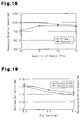
- Fig. 17 is a graph showing the relationship between the quantity of ribs and the maximum deflection amount of top plates of first, second, fourth, and sixth test samples on which radial ribs are arranged only on one side of each top plate;
- Fig. 18 is a graph showing the relationship between the quantity of ribs and the resonance rotation speed of top plates of first, second, fourth, and sixth test samples on which radial ribs are arranged only on one side of each top plate;
- Fig. 19 is a graph showing the relationship between the depth of ribs and the maximum deflection amount of top plates of
test samples 3 and 5 on which radial ribs are arranged on both sides of each top plate; - Fig. 20 is a graph showing the relationship between the depth of ribs and the resonance rotation speed of top plates of
test samples 3 and 5 on which radial ribs are arranged on both sides of each top plate; - Fig. 21 is a bottom view showing a top plate structure for a high location installation type air conditioner according to a second embodiment of the present invention;
- Fig. 22 is a vertical cross-sectional view taken along line 22-22 of Fig. 24 showing an overall structure of a conventional air conditioner;
- Fig. 23 is a bottom view showing the conventional air conditioner from which a decorative panel and a body casing are removed and viewed from below; and
- Fig. 24 is an exploded perspective view showing the attachment position relationship between a top plate and a bell mouth of the conventional air conditioner.
- Figs. 1 to 6 show a top plate structure for a high location installation type air conditioner according to a first embodiment of the present invention.
- A
top plate 32 of the first embodiment is optimal for application to abody casing 3 of a ceiling concealed air conditioner (indoor unit) that is substantially the same as that of the conventional example described with reference to Figs. 22 to 24. - As shown in Fig. 4, the
top plate 32 has a plate thickness D4 set at 0.7 mm, which is smaller than a thickness of 0.8 mm of a conventional top plate. As shown Figs. 1 and 2, thetop plate 32 is hexagonal and shaped in correspondence with thecassette body casing 3 of the air conditioner. Thetop plate 32 has a peripheral portion along which a hook-shapedrim portion 32c is formed to be fitted with the peripheral portion of an upper end of thebody casing 3. - In the same manner as in the conventional system shown in Figs. 22 to 24, the
top plate 32 has acentral portion 33 supporting a fan 5 and afan motor 9 and a peripheral portion supporting a generallyannular heat exchanger 4. As shown in Figs. 4 and 5, thetop plate 32 includes two different kinds of reinforcing ribs, namely, a plurality of radially extending reinforcingribs 32a and a plurality of radially extending reinforcingribs 32a'. The reinforcingribs central portion 33 to the peripheral portion of thetop plate 32. The reinforcingribs top plate 32. The reinforcingribs ribs 32a, among the reinforcingribs step portion 32b. Thestep portion 32b of each reinforcingrib 32a is recessed downward with a depth D3 smaller than the depth D2 by a predetermined dimension. - The
top plate 32 further has a reinforcingrib 33a having a depth D1 arranged on a supporting portion for the fan 5 and thefan motor 9 in thecentral portion 33. The depth D1 is equal to the depth D2. The reinforcingrib 33a extends between five fan motor support portions a to e, which enable supporting at three points or four points, and is in contact with the fan motor support portions a to e. The reinforcingrib 33a effectively improves rigidity, strength, deflection, and vibration characteristics of the supporting portion of the fan 5 and thefan motor 9. - As shown in Fig. 1, heavy components including the
heat exchanger 4, the fan 5, and thefan motor 9 are attached to thetop plate 32 in the same manner as in the conventional structure. - As described above, the structure of the present embodiment includes the
radial reinforcing ribs 32a' and 32a extending from thecentral portion 33 of thetop plate 32 on which thefan motor 9 is supported to the peripheral portion of thetop plate 32 on which theheat exchanger 4 is supported. The reinforcingribs 32a' protrude from the front surface of thetop plate 32, and the reinforcingribs 32a protrude from the rear surface of thetop plate 32. - With this top plate structure, even when the
top plate 32 is formed to have a smaller plate thickness than the conventional top plate, by optimally adjusting and setting the quantity and the cross-sectional shape (diaphragm shape) of the reinforcingribs 32a' and 32a in a wide range, thetop plate 32 may be improved to the required levels for rigidity, strength, deflection characteristics, vibration characteristics, and the like. In particular, the structure in which the reinforcing rib portions protrude both from the front surface and the rear surface of thetop plate 32 substantially doubles the vertical wall height dimensions of thetop plate 32 between its front and rear surfaces and greatly improves rigidity of thetop plate 32 against deflection. This structure reduces the plate thickness of thetop plate 32 and facilitates the formation of thetop plate 32, thereby reducing the manufacturing cost of thetop plate 32. - Further, the reinforcing
ribs 32a' protruding from the front surface of thetop plate 32 and the reinforcingribs 32a protruding from the rear surface of thetop plate 32 are arranged alternately in the circumferential direction. This structure improves the supporting rigidity of thetop plate 32 in a balanced manner throughout the entiretop plate 32 and uniformly reduces the maximum deflection amount of thetop plate 32 throughout the entiretop plate 32. - The reinforcing
ribs 32a' and 32a are each formed to have a depth h that changes so as to decrease as the two end portions in the longitudinal direction (radial direction) become closer and increase as the portion between the two end portions become closer. When h1 represents the depth of the two end portions of each reinforcing rib and h2 represents the depth of the intermediate portion between the two end portions, h1 < h2 is satisfied. - In this manner, the depth of each of the reinforcing
ribs top plate 32, improves the resonance rotation speed of thetop plate 32, and reduces the cost of thetop plate 32 by lowering material cost. - In the present embodiment, the plate thickness of the
top plate 32 is set in the range of 0.6 to 0.7 mm. The material cost for thetop plate 32 decreases and press formation of thetop plate 32 is facilitated as the plate thickness of thetop plate 32 decreases. However, the strength and rigidity of thetop plate 32 decreases and the deflection and vibration characteristics of thetop plate 32 deteriorate as the plate thickness of thetop plate 32 decreases. The reinforcingribs 32a' and 32a having the above-described structure effectively prevent such characteristics of thetop plate 32 from deteriorating. However, thetop plate 32 still needs to have a certain level of plate thickness. - Various experiments have been conduced from the viewpoints described above. The experimental results indicate that the top plate structure using the reinforcing
ribs 32a' and 32a described above enables the plat thickness of thetop plate 32 to be reduced to a range of 0.6 to 0.7 mm. The structure enables thetop plate 32 with such reduced plate thicknesses to have sufficiently high supporting rigidity and stable vibration characteristics. As a result, the cost of thetop plate 32 can be expected to be effectively decreased by the lowered material cost. - This range of plate thickness is optimum for lowering the material cost of the
top plate 32, facilitating formation of thetop plate 32, and ensuring the required quality performance. This plate thickness range is determined based on the relationship between the plate thickness of the conventional top plate and the reinforcing effect of the reinforcing ribs described above. - The top plate structure for the high location installation type air conditioner according to the preferred embodiment enables the top plate to have stable supporting rigidity, supporting strength, and low-noise performance while reducing the thickness of the top plate and reducing the cost of the top plate.
- Analytical experiments described below verify the effect of the
radial reinforcing ribs 32a' and 32a protruding from the front and rear surfaces of the top plate. - First, four models of top plates that differ from one another in the quantity of reinforcing ribs shown in Fig. 7 (six ribs), Fig. 9 (eight ribs), Fig. 12 (ten ribs), and Fig. 15 (12 ribs) irrespective of the protruding direction of the ribs are used as basic models. A top
plate having ribs 32a arranged only on one side and a topplate having ribs 32a' and 32a arranged on two sides were prepared using each of the basic models of Fig. 9 (eight ribs) and Fig. 12 (ten ribs). A topplate having ribs 32a arranged only on one side was prepared using each of the basic models of Fig. 7 (six ribs) and Fig. 15 (twelve ribs). The six top plates 32A to 32F of test samples 1 to 6 were prepared in total. All the top plates 32A to 32F have the plate thickness of 0.7 mm. Refer to Table 1 for the specifications of thetop plates 32A and 32F. - In Table 1, the root R (mm) indicates the radius of an arc linking basal ends of a pair of adjacent reinforcing ribs.
Table 1 Sample No. 1 2 3 4 5 6 Quantity 6 8 8 10 10 12 Width W (mm) 60.0 Length L (mm) 696.0 Root R (mm) 81.0 39.0 39.0 20.0 20.0 9.5 Depth h (mm) One Side 9.5 6.0 - 9.5 - 9.5 Two Sides - - 8.0 - 9.5 - - As shown in Fig. 7, the first top plate 32A includes six reinforcing
ribs 32a that are arranged at equal intervals of 60 degrees in the circumferential direction. The dimension (length) between the two distal ends of two opposing reinforcingribs 32a arranged at an interval of 180 degrees is 696.0 mm. Each reinforcingrib 32a has a groove width W of 60.0 mm. The reinforcingribs 32a protrude from only either one of the front surface and the rear surface of the top plate 32A (refer to Fig. 8). - As shown in Fig. 9, the second top plate 32B includes eight reinforcing
ribs 32a that are arranged at equal intervals of 45 degrees in the circumferential direction. The dimension (length) between the two distal ends of two opposing reinforcingribs 32a arranged at an interval of 180 degrees is 696.0 mm. Each reinforcingrib 32a has a groove width W of 60.0 mm. The reinforcingribs 32a protrude from only either one of the front surface and the rear surface of the top plate 32B (refer to Fig. 10). - As shown in Fig. 9, the third top plate 32C includes eight reinforcing
ribs 32a' and 32a that are arranged at equal intervals of 45 degrees in the circumferential direction. The dimension (length) between the two distal ends of two opposing reinforcingribs 32a' and 32a arranged at an interval of 180 degrees is 696.0 mm. Each of the reinforcingribs 32a' and 32a has a groove width W of 60.0 mm. The reinforcingribs 32a' and 32a protrude alternately from both the front surface and the rear surface of the top plate 32C (refer to Fig. 11). - As shown in Fig. 12, the fourth
top plate 32D includes ten reinforcingribs 32a that are arranged at equal intervals of 36 degrees in the circumferential direction. The dimension (length) between the two distal ends of two opposing reinforcingribs 32a' and 32a arranged at an interval of 180 degrees is 696.0 mm. Each reinforcingrib 32a has a groove width W of 60.0 mm. The reinforcingribs 32a protrude from only either one of the front surface and the rear surface of thetop plate 32D (refer to Fig. 13). - As shown in Fig. 12, the fifth
top plate 32E includes ten reinforcingribs 32a' and 32a that are arranged at equal intervals of 36 degrees in the circumferential direction. The dimension (length) between the two distal ends of two opposing reinforcingribs 32a' and 32a arranged at an interval of 180 degrees is 696.0 mm. Each of the reinforcingribs 32a' and 32a has a groove width W of 60.0 mm. The reinforcingribs 32a' and 32a protrude alternately from both the front surface and the rear surface of thetop plate 32E (refer to Fig. 14). - As shown in Fig. 15, the sixth
top plate 32F includes twelve reinforcingribs 32a that are arranged at equal intervals of 30 degrees in the circumferential direction. The dimension (length) between the two distal ends of two opposing reinforcingribs 32a arranged at an interval of 180 degrees is 696.0 mm. Each reinforcingrib 32a has a groove width W of 60.0 mm. The reinforcingribs 32a protrude from only either one of the front surface and the rear surface of thetop plate 32F (refer to Fig. 16). - The influence of the quantity of ribs on the maximum deflection amount and the resonance rotation speed of each
top plate 32 having theradial reinforcing ribs 32a protruding from only one side are shown in Table 2 and the graphs in Figs. 17 and 18. The reinforcingribs 32a all have the same width W, length L, and depth h.Table 2 Rib Specifications Maximum Deflection (mm) Resonance Rotation Speed Quantity Depth (mm) Primary Secondary 6 9.5 1.60 784.0 990.0 8 9.5 1.35 907.0 990.0 10 9.5 1.32 914.0 940.0 12 9.5 1.41 890.0 917.0 - The following findings were obtained from the analysis results shown in Table 2 and the graphs in Figs. 17 and 18.
- The overall static characteristics and dynamic characteristics of the
top plate 32 including eight reinforcingribs 32a and thetop plate 32 including ten reinforcingribs 32a are superior to the static and dynamic characteristics of thetop plate 32 including six reinforcingribs 32a and thetop plate 32 including twelve reinforcingribs 32a. - The
top plate 32 including eight reinforcingribs 32a and thetop plate 32 including ten reinforcingribs 32a have substantially the same deflection amount (1.35/1.32 mm) and substantially the same primary resonance rotation speed (907.0/914.0 rpm). However, thetop plate 32 including eight ribs has the secondary resonance rotation speed of 990.0 rpm, and thetop plate 32 including ten ribs has the secondary resonance rotation speed of 940.0 rpm, which is 5.0% lower than the secondary resonance rotation speed of thetop plate 32 including eight ribs. Thetop plate 32 including eight reinforcingribs 32a is assumed to have the best static and dynamic characteristics. - The influence of the depth h of the radial ribs on the maximum deflection amount and the resonance rotation speed of the
top plate 32 including eight radial reinforcing ribs protruding from one side (32a) and thetop plate 32 including radial reinforcing ribs protruding from two sides (32a' and 32a) is shown in Table 3 and the graphs in Figs. 19 and 20.Table 3 Rib Specifications Maximum Deflection (mm) Resonance Rotation Speed (rpm) Quantity Depth (mm) One Side Two Sides Primary Secondary Two Sides One Side Two Sides One Side 8 6.0 1.89 2.03 786.0 754.0 925.0 816.0 8.0 1.39 1.57 899.0 848.0 1033.0 915.0 9.5 1.16 1.35 970.0 907.0 1115.0 990.0 10 9.5 1.17 1.32 936.0 914.0 1061.0 940.0 - The following findings are obtained from the analysis results.
- The
top plates 32 having the single-side rib arrangement (32a) and the double-side rib arrangement (32a' and 32a) both have a smaller maximum deflection amount and a higher resonance rotation speed as the depth of their ribs increases. This indicates that an increase in the rib depth improves the static characteristics of thetop plates 32. - Table 3 and the graphs in Figs. 19 and 20 show that the
top plates 32 having the double-side rib arrangement have better static and dynamic characteristics than thetop plates 32 having the single-side rib arrangement. - The inventors of the present application further researched changes in the maximum deflection amount and the resonance rotation speed resulting from different rib depths of the
top plate 32 when using a plurality of parallel ribs in lieu of the radial ribs described above. More specifically, the inventors measured the maximum deflection amount and the resonance rotation speed of thetop plates 32 having a single-side rib arrangement of parallel ribs and a double-side rib arrangement of parallel ribs. - The measurement results show that the maximum deflection amount and the resonance rotation speed of the
top plate 32 are significantly affected by the rib depth when the depth of the parallel ribs is 2.0 to 6.0 mm and relatively shallow. This indicates that small differences in the rib depth greatly change the maximum deflection amount and the resonance rotation speed of thetop plates 32 when the rib depth is relatively small. Thus, robustness of the static and dynamic characteristics of thetop plates 32 with respect to the rib depth is low when the rib depth is relatively small. - When the rib depth is 8.0 to 12.0 mm and relatively large, the influence of the rib depth on the maximum deflection amount and the resonance rotation speed of the
top plates 32 decreases. This indicates that small differences in the rib depth do not greatly change the maximum deflection amount and the resonance rotation speed of thetop plate 32 when the rib depth is relatively large. Thus, robustness of the static and dynamic characteristics of thetop plates 32 with respect to the rib depth is high when the rib depth is relatively large. - When the rib depth is 14.0 to 18.0 mm and deep, the influence of the rib depth on the maximum deflection amount and the resonance rotation speed of the
top plates 32 is limited. This indicates that differences in the rib depth only slightly change the maximum deflection amount and the resonance rotation speed of thetop plate 32 when the rib depth is large. Thus, robustness of the static and dynamic characteristics of thetop plates 32 with respect to the rib depth is high when the rib depth is large. - These findings are also substantially applicable to top plates including radial reinforcing ribs.
- The design standard requires that the maximum deflection amount of the
top plate 32 be suppressed at 1.31 mm or less and that the resonance rotation speed be maintained at 742.0 rpm or higher. - The rib depth is preferably 8.0 to 10.0 mm to satisfy the design standard while maintaining robustness of the static and dynamic characteristics of the
top plate 32 with respect to the rib depth. - Fig. 21 shows a top plate structure for a high location installation type air conditioner according to a second embodiment of the present invention.
- A
top plate 32 of the second embodiment is also optimal for application to abody casing 3 of a ceiling concealed air conditioner (indoor unit) that is substantially the same as that in the conventional example shown in Figs. 22 to 24. - The
top plate 32 is formed to have a plate thickness of about 0.7 mm, which is smaller than the thickness of 0.8 mm of the conventional top plate. Thetop plate 32 is hexagonal and shaped in correspondence with thecassette body casing 3 of the air conditioner shown in Figs. 22 to 24. Thetop plate 32 has a peripheral portion along which a hook-shapedrim portion 32c is formed to be fitted with the peripheral portion of an upper end of thebody casing 3. - A fan 5 and a
fan motor 9 identical to the structures shown in Figs. 22 to 24 are supported on acentral portion 33 of thetop plate 32. A generallyannular heat exchanger 4 is supported on the peripheral portion of thetop plate 32. In the same manner as in the first embodiment, thetop plate 32 includes a plurality of radially extending main reinforcingribs 32a extending from thecentral portion 33 to the peripheral portion of thetop plate 32. The main reinforcingribs 32a protrude from a rear surface of thetop plate 32. The main reinforcingribs 32a each have an inverted trapezoidal cross-section and each have a bottom surface width W1, a top width W2, a depth D2, and an inclination angle θ2. A heat exchanger support portion located on the outer side of each main reinforcingrib 32a has astep portion 32b. Thestep portion 32b is recessed downward with a depth D3 that is smaller than the depth D2 by a predetermined dimension (the dimension not shown). - The
top plate 32 further has a reinforcingrib 33a having a depth D1 arranged on a supporting portion for the fan 5 and thefan motor 9 in thecentral portion 33. The depth D1 is equal to the depth D2. The reinforcingrib 33a extends between five fan motor support portions a to e, which enable supporting at three points or four points, and is in contact with the fan motor support portions a to e. - This structure effectively improves basic rigidity, strength, deflection, and vibration characteristics of the supporting portion of the fan 5 and the
fan motor 9. However, the interval between the main reinforcingribs 32a in the peripheral portion of thetop plate 32 is large. As a result, the peripheral portion of thetop plate 32 may have insufficient rigidity, strength, etc. - Therefore, the
top plate 32 further has a plurality ofsub-reinforcing ribs 34 arranged between the main reinforcingribs 32a as shown in the drawing. The shape and dimensions of the sub-reinforcing ribs are determined in accordance with the load assumed to be applied to thetop plate 32. In the structure of the present embodiment, the main reinforcingribs 32a protrude from the rear surface of thetop plate 32, and thesub-reinforcing ribs 34 protrude from the surface opposite to the surface from which the main reinforcingribs 32a protrude. - This structure reduces the static deflection of the
top plate 32 to a fixed value or lower and maintains the primary natural vibration frequency of thetop plate 32 at a fixed value or greater to avoid resonance caused by rotation of thefan motor 9. - Heavy components including the
heat exchanger 4, the fan 5, and thefan motor 9 are attached to thetop plate 32 having the above-described structure in the same manner as in the conventional structure. - As described above, the plurality of reinforcing ribs in the second embodiment include the long main reinforcing
ribs 32a and the shortsub-reinforcing ribs 34 arranged between the long reinforcingribs 32a, and the main reinforcingribs 32a protrude from either one of the front surface and the rear surface of thetop plate 32, and thesub-reinforcing ribs 34 protrude from the surface opposite the surface from which the main reinforcingribs 32a protrude. - The structure having the
sub-reinforcing ribs 32a also has the same advantages as described in the first embodiment. This structure improves the supporting rigidity of thetop plate 32 in a balanced manner throughout the entiretop plate 32 and uniformly reduces the maximum deflection amount of thetop plate 32. - This structure also reduces the sufficient plate thickness of the
top plate 32 to 0.6 to 0.7 mm.
Claims (6)
- A top plate structure for an air conditioner including a body casing (3) for accommodating a fan (5), a fan motor (9), and a heat exchanger (4), and a top plate (32) forming a top surface of the body casing for suspending the fan (5), the fan motor (9), and the heat exchanger (4), wherein the top plate (32) has a plurality of radial reinforcing ribs extending from a central portion of the top plate at which the fan motor (9) is supported to a peripheral portion of the top plate at which the heat exchanger (4) is supported, the top plate structure being characterized in that:the plurality of reinforcing ribs include a reinforcing rib (32a') protruding from a front surface of the top plate (32) and a reinforcing rib (32a) protruding from a rear surface of the top plate.
- The top plate structure according to claim 1, characterized in that the reinforcing rib (32a') protruding from the front surface of the top plate (32) and the reinforcing rib (32a) protruding from the rear surface are alternately arranged in a circumferential direction of the top plate (32).
- The top plate structure according to claim 1 or 2, characterized in that the plurality of reinforcing ribs include a plurality of long main reinforcing ribs (32a) and a plurality of short sub-reinforcing ribs (34) arranged between the main reinforcing ribs (32a), and the main reinforcing ribs protrude from one of a front surface and a rear surface of the top plate (32) and the sub-reinforcing ribs (34) protrude from the other one of the front surface and the rear surface of the top plate.
- The top plate structure according to any one of claims 1 to 3, characterized in that the reinforcing ribs (32a'), (32a), (34) each have a depth that changes in a longitudinal direction of the reinforcing rib, and the depth at two end portions of each reinforcing rib is less than the depth between the two end portions.
- The top plate structure according to any one of claims 1 to 4, characterized in that the top plate (32) has a plate thickness that is set in a range of 0.6 to 0.7 mm.
- The top plate structure according to any one of claims 1 to 5, characterized in that the reinforcing ribs (32a'), (32a), (34) each have a depth of 8.0 to 10.0 mm.
Applications Claiming Priority (2)
| Application Number | Priority Date | Filing Date | Title |
|---|---|---|---|
| JP2005115994A JP2006292312A (en) | 2005-04-13 | 2005-04-13 | Top plate structure of high place-installation type air conditioner |
| PCT/JP2006/307462 WO2006112278A1 (en) | 2005-04-13 | 2006-04-07 | Top plate structure of air conditioner for installation at high level |
Publications (1)
| Publication Number | Publication Date |
|---|---|
| EP1867930A1 true EP1867930A1 (en) | 2007-12-19 |
Family
ID=37115004
Family Applications (1)
| Application Number | Title | Priority Date | Filing Date |
|---|---|---|---|
| EP06731409A Withdrawn EP1867930A1 (en) | 2005-04-13 | 2006-04-07 | Top plate structure of air conditioner for installation at high level |
Country Status (5)
| Country | Link |
|---|---|
| US (1) | US20080159848A1 (en) |
| EP (1) | EP1867930A1 (en) |
| JP (1) | JP2006292312A (en) |
| CN (1) | CN101147031A (en) |
| WO (1) | WO2006112278A1 (en) |
Cited By (1)
| Publication number | Priority date | Publication date | Assignee | Title |
|---|---|---|---|---|
| EP2023049A3 (en) * | 2007-07-25 | 2009-02-25 | Sanyo Electric Co., Ltd. | In-ceiling mount type air conditioner and indoor unit thereof |
Families Citing this family (11)
| Publication number | Priority date | Publication date | Assignee | Title |
|---|---|---|---|---|
| KR101234828B1 (en) * | 2007-02-16 | 2013-02-20 | 삼성전자주식회사 | Air-Conditioner |
| JP2011257068A (en) | 2010-06-09 | 2011-12-22 | Mitsubishi Heavy Ind Ltd | Cabinet for air conditioner and air conditioner using the same |
| CN103430257B (en) | 2011-03-17 | 2016-03-16 | 丰田自动车株式会社 | The housing of electric equipment |
| JP5516495B2 (en) * | 2011-04-27 | 2014-06-11 | 三洋電機株式会社 | Indoor unit of ceiling-embedded air conditioner |
| JP2011185596A (en) * | 2011-04-27 | 2011-09-22 | Sanyo Electric Co Ltd | Indoor unit of ceiling-embedded air conditioning device |
| JP2012088038A (en) * | 2011-11-28 | 2012-05-10 | Sanyo Electric Co Ltd | Indoor unit for ceiling-embedded air conditioning device |
| FR2989770B1 (en) * | 2012-04-19 | 2018-06-15 | Valeo Systemes Thermiques | HEAT EXCHANGER BEAM COVER, BEAM INCLUDING SUCH COVER, HEAT EXCHANGER COMPRISING SUCH BEAM, AND AIR INTAKE MODULE COMPRISING SUCH AN EXCHANGER. |
| JP6458984B2 (en) * | 2014-10-10 | 2019-01-30 | 株式会社富士通ゼネラル | Embedded ceiling air conditioner |
| JP6649311B2 (en) * | 2017-03-24 | 2020-02-19 | 株式会社東芝 | High rigidity plate and air conditioner |
| JP6428895B2 (en) * | 2017-11-07 | 2018-11-28 | 新日鐵住金株式会社 | Indoor unit top plate |
| WO2019144212A1 (en) | 2018-01-29 | 2019-08-01 | Dana Canada Corporation | Structurally supported heat exchanger |
Family Cites Families (8)
| Publication number | Priority date | Publication date | Assignee | Title |
|---|---|---|---|---|
| US2554874A (en) * | 1949-01-21 | 1951-05-29 | Warner Electric Brake & Clutch | Magnetic friction element |
| US2638757A (en) * | 1951-05-05 | 1953-05-19 | Int Harvester Co | Ceiling mounted air-conditioning apparatus |
| US4574551A (en) * | 1984-05-23 | 1986-03-11 | Giannuzzi Louis | Load-bearing plate |
| JP2592647Y2 (en) * | 1992-03-11 | 1999-03-24 | ダイキン工業株式会社 | Air conditioner |
| JP3306944B2 (en) * | 1993-01-26 | 2002-07-24 | 株式会社日立製作所 | Air conditioner indoor unit |
| JP4462389B2 (en) * | 1998-11-20 | 2010-05-12 | 株式会社富士通ゼネラル | Air conditioner |
| US6598413B2 (en) * | 1999-01-25 | 2003-07-29 | Mitsubishi Denki Kabushiki Kaisha | Ceiling embedded-type air conditioner |
| US6487870B2 (en) * | 1999-12-13 | 2002-12-03 | Ff Seeley Nominees Pty Ltd | Transition support for evaporative cooler |
-
2005
- 2005-04-13 JP JP2005115994A patent/JP2006292312A/en not_active Withdrawn
-
2006
- 2006-04-07 WO PCT/JP2006/307462 patent/WO2006112278A1/en active Application Filing
- 2006-04-07 CN CNA200680008956XA patent/CN101147031A/en active Pending
- 2006-04-07 US US11/884,701 patent/US20080159848A1/en not_active Abandoned
- 2006-04-07 EP EP06731409A patent/EP1867930A1/en not_active Withdrawn
Non-Patent Citations (1)
| Title |
|---|
| See references of WO2006112278A1 * |
Cited By (2)
| Publication number | Priority date | Publication date | Assignee | Title |
|---|---|---|---|---|
| EP2023049A3 (en) * | 2007-07-25 | 2009-02-25 | Sanyo Electric Co., Ltd. | In-ceiling mount type air conditioner and indoor unit thereof |
| US9255716B2 (en) | 2007-07-25 | 2016-02-09 | Panasonic Intellectual Property Management Co., Ltd. | In-ceiling mount type air conditioner and indoor unit thereof |
Also Published As
| Publication number | Publication date |
|---|---|
| JP2006292312A (en) | 2006-10-26 |
| CN101147031A (en) | 2008-03-19 |
| WO2006112278A1 (en) | 2006-10-26 |
| US20080159848A1 (en) | 2008-07-03 |
Similar Documents
| Publication | Publication Date | Title |
|---|---|---|
| EP1867930A1 (en) | Top plate structure of air conditioner for installation at high level | |
| US7805957B2 (en) | Top plate structure for air conditioner installed at high location | |
| EP1775518B1 (en) | Top plate structure for air conditioner installed at high place | |
| US8272838B2 (en) | Impeller and pump including the same | |
| JP4671007B2 (en) | Split air conditioner outdoor unit | |
| US6218752B1 (en) | Motor mount assembly for an air conditioner | |
| KR101537589B1 (en) | A Duct Type Air Conditioner | |
| US20160025103A1 (en) | Centrifugal fan | |
| JP3532868B2 (en) | Air conditioner motor mounting structure | |
| JP4623253B2 (en) | Split air conditioner outdoor unit | |
| EP1847718B1 (en) | Axial flow fan | |
| KR20120006744U (en) | Impeller for exhaust water pump | |
| US9660498B2 (en) | Motor mount with improved decoupling for ventilation system | |
| TW201730440A (en) | Impeller with structure for adjusting counterweight and fan with the impeller | |
| CN107449060B (en) | Window type air conditioner | |
| JP2003214658A (en) | Outdoor unit of air conditioner | |
| US20050053486A1 (en) | Offset mounting foot | |
| CN214664787U (en) | Air duct machine and bearing seat thereof | |
| CN214626613U (en) | Bearing seat, bearing assembly and air duct machine | |
| JP7376949B2 (en) | drain pump | |
| JP2004190992A (en) | Outdoor machine for air conditioner | |
| JP2010265794A (en) | Sealed electric compressor | |
| JP2005055129A (en) | Compressor support structure | |
| JP2013213621A (en) | Ceiling embedded type air conditioner | |
| EP1657450A1 (en) | A plate for a fan |
Legal Events
| Date | Code | Title | Description |
|---|---|---|---|
| PUAI | Public reference made under article 153(3) epc to a published international application that has entered the european phase |
Free format text: ORIGINAL CODE: 0009012 |
|
| 17P | Request for examination filed |
Effective date: 20070828 |
|
| AK | Designated contracting states |
Kind code of ref document: A1 Designated state(s): AT BE BG CH CY CZ DE DK EE ES FI FR GB GR HU IE IS IT LI LT LU LV MC NL PL PT RO SE SI SK TR |
|
| DAX | Request for extension of the european patent (deleted) | ||
| STAA | Information on the status of an ep patent application or granted ep patent |
Free format text: STATUS: THE APPLICATION HAS BEEN WITHDRAWN |
|
| 18W | Application withdrawn |
Effective date: 20090304 |