JP4671007B2 - Split air conditioner outdoor unit - Google Patents
Split air conditioner outdoor unit Download PDFInfo
- Publication number
- JP4671007B2 JP4671007B2 JP2001067286A JP2001067286A JP4671007B2 JP 4671007 B2 JP4671007 B2 JP 4671007B2 JP 2001067286 A JP2001067286 A JP 2001067286A JP 2001067286 A JP2001067286 A JP 2001067286A JP 4671007 B2 JP4671007 B2 JP 4671007B2
- Authority
- JP
- Japan
- Prior art keywords
- base plate
- outdoor unit
- partition plate
- operation valve
- heat exchanger
- Prior art date
- Legal status (The legal status is an assumption and is not a legal conclusion. Google has not performed a legal analysis and makes no representation as to the accuracy of the status listed.)
- Expired - Fee Related
Links
Images


Description
【0001】
【発明の属する技術分野】
本発明はスプリット型エアコンの室外機に関し、さらに詳しく言えば、剛性が高い筐体構造を有するとともに、運転時の騒音・振動が少なく、よりコンパクト化が可能なスプリット型エアコンの室外機に関するものである。
【0002】
【従来の技術】
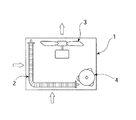
スプリット型エアコン(空気調和機)においては、室内機と室外機とが配管を介して接続され、室外機は屋外の例えば庭先やベランダ、屋根上などに設置される。図19に、一般的な室外機の内部構造を平面視にて模式的に示す。
【0003】
通常、室外機は箱形の筐体1を備え、その内部には熱交換器2、送風ファン3および圧縮機4などが収納されている。多くの場合、熱交換器2は一つであり、筐体1の一つ面に沿って平面的に配置されるものもあるが、通常においては、この例のように、筐体1の2つの面に沿ってほぼL字型に配置されている。
【0004】
その関係上、圧縮機4は筐体1のコーナーに設置され、また、送風ファン3は熱交換器2の下流側に配置されている。なお、図示されていないが、圧縮機4の周辺には電装品箱や操作弁取付基板などが設けられている。
【0005】
【発明が解決しようとする課題】
しかしながら、このような部品配置では次のような課題があった。まず、筐体が天井面側からの荷重に対して弱く変形をきたしやすい。圧縮機の周りに特に仕切り板が設けられていないため、運転時に騒音が外に出やすい。
【0006】
また、送風ファンについても、主として筐体のベース板側に支持されているため、運転時の振動がベース板で増幅された後筐体全体に伝達され、極端な場合には共振により大きな騒音が発生する。また、例えば搬送時の落下衝撃などにより、ベース板が変形した場合圧縮機が傾いてしまい、そのまま設置されて運転されることがある。
【0007】
圧縮機が筐体のコーナー部に配置されているため、室外機の重心が偏っている。すなわち、重量バランスが悪いため持ち運びにくく、特に梯子などで高所に持ち上げる場合に作業者に余計な負担を強いることになる。
【0008】
また、熱交換器が一つでL字型配置であるため、性能を落とすことなく小型化するにも自ずと限界があった。したがって、例えば今まで使用していた一体型エアコンに代えてスプリット型エアコンを買い換えた場合、一体型エアコン設置用として壁孔から屋外側に張り出すように設計された既設の設置台に室外機を置くことになるが、従来の室外機は一様に大きすぎるため、既設の設置台を改造しなければならないなどの不便さがあった。
【0009】
本発明は、このような課題を解決するためになされたもので、その目的は、剛性が高い筐体構造を有するとともに、運転時の騒音・振動がともに少なく、しかも高性能でよりコンパクト化されたスプリット型エアコンの室外機を提供することにある。
【0010】
【課題を解決するための手段】
上記目的を達成するため、本発明のスプリット型エアコンの室外機は、ほぼ矩形状に形成されたベース板と、上記ベース板の左右両側に配置され、各一端側の一部分が背面側に回り込むようにほぼL字状に折り曲げられた左右一対の熱交換器と、上記ベース板の背面側のほぼ中央部に設けられた圧縮機と、上記圧縮機の周りを囲むように上記ベース板上に取り付けられた仕切り板と、上記仕切り板の前面側にモータ支持台を介して取り付けられた送風機と、上記ベース板の前面側に配置されたファンリングと、上記ファンリングおよび上記熱交換器を覆って上記ベース板に固定された外胴とを備え、上記仕切り板は、上記ベース板から上記外胴の天井面までの高さにほぼ等しい高さであるとともに、上記各熱交換器の背面側端部間に配置される開口部を有し、上記開口部の開口面に沿って電装品箱と操作弁取付基板とが配置されていることを特徴としている。
【0011】
このように、ベース板のほぼ中央に圧縮機および送風機を配置し、その両側に左右対称的に2つの熱交換器を配置するとともに、ファンリングと両方の熱交換器を外胴で固定するようにしたことにより、筐体の剛性が高められるとともに、全体的に重量バランスがよく、しかも高性能を維持しながらコンパクトに設計できる。また、圧縮機の周りに仕切り板が設けられているため低騒音でもある。
【0012】
また、本発明において、上記仕切り板は、上記ベース板から上記外胴の天井面までの高さにほぼ等しい高さであるとともに、上記各熱交換器の背面側端部間に配置される開口部を有し、その開口部の開口面に沿って電装品箱と操作弁取付基板とが配置されることにより、筐体の剛性がより高められ、また、より一層の低騒音化が可能となる。
【0013】
さらに、筐体の剛体化を図るうえで、熱交換器に対する係止手段を備えた天井補強板をファンリングの上部に設けることが好ましい。また、仕切り板の上端に上部フランジを形成して外胴の天井面を支えるようにするとよい。
【0014】
また、組み立て作業性の観点から、仕切り板の下端側にベース板側に向けて斜め下方に折り曲げられた位置決め兼ネジ止め用の係止片を設け、ベース板側には係止片がネジ止めされる受け板を形成することが好ましい。
【0015】
遮音効果を高めるには、仕切り板の内面に遮音材を設けるとよい。また、仕切り板の一部分に放熱用のルーバーを形成することにより、圧縮機周りの電気部品の寿命を長くすることができる。
【0016】
仕切り板を左右対称形状とすることにより、筐体内への吸込風量が左右でほぼ等しくなるため、2つの熱交換器に同じものが使用できる。すなわち、熱交換器の共用化が図れる。
【0017】
筐体の剛体化を図るため、モータ支持台は仕切り板とともに外胴の天井面を支持するように、その上端が仕切り板の上端に固定され、下端側がベース板に固定されることが好ましい。
【0018】
本発明の好ましい態様によれば、送風機の振動を抑えるため、モータ支持台に仕切り板に当接して同仕切り板との間隔を一定に保つスペーサが設けられる。スペーサは、モータ支持台から一体に折り曲げられた板材からなるが、仕切り板に対する当接面に絞り加工による凸部を形成することにより、振動伝達面を小さくできる。
【0019】
また、モータ支持台のベース板に固定される下端側に、同モータ支持台よりも幅広の固定フランジを連設して、ベース板との一体化を図ることにり、送風機の振動がより効果的に抑えられる。
【0020】
ベース板には、その四隅に設けられている設置台に対する設置用脚部とは別に、圧縮機の周りに同ベース板を下側に凹ませてなる圧縮機用支持脚が少なくとも3箇所に設けられていることも、本発明の特徴の一つであり、これによれば、圧縮機の振動がその支持脚によって減衰される。
【0021】
圧縮機用支持脚は、設置用脚部よりも低く、圧縮機の重量によるベース板の撓みにより設置台に接するようにすることが好ましく、これにれば、仮にベース板に搬送時などの落下衝撃により歪が生じたとしても、圧縮機が傾いて設置されるおそれがなくなる。より好ましくは、圧縮機用支持脚は、圧縮機の周りに同心円上に等間隔で配置され、圧縮機を中心とする所定曲率の円弧状に形成される。
【0022】
また、本発明の好ましい態様によれば、配管および電気配線作業を容易とするため、電装品箱が上側で、その下側に操作弁取付基板が配置され、操作弁取付基板には、二方操作弁と三方操作弁の2つの操作弁が水平方向に所定の間隔をもって離された状態で、三方操作弁が二方操作弁よりも上部位置に配置される。また、電装品箱内の配線接続部が、二方操作弁の上方に配置される。
【0023】
仕切り板が左右非対称形で、左右の熱交換器で吸込風量が異なる場合には、吸込風量が多い方の熱交換器側の熱交換能力が吸込風量が少ない方の熱交換器側の熱交換能力よりも大きく設定されることが好ましい。
【0024】
その方法としては、冷媒配管の列数によってもよいし、熱交換器のフィンピッチもしくはフィン幅によってもよく、また、熱交換器のフィンに設けられるスリットもしくはルーバーによってもよい。
【0025】
【発明の実施の形態】
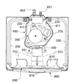
次に、本発明の実施形態について説明する。まず、図1の分解斜視図、図2の平面透視図および図3の側面透視図を参照して、この実施形態に係る室外機が備える基本的な構成要素について説明する。
【0026】
この室外機は、ほぼ矩形状に形成されたベース板100と、ベース板100の左右両側に配置される左右一対の熱交換器200,200とを備えている。この実施形態において、ベース板100は金属板からなり、その四隅の各々に下側に向けて凸とされた設置用脚部110が形成されている。図3には、四隅に設けられる設置用脚部110の内の2つが示されている。
【0027】
各熱交換器200は、その一端側の一部分がベース板100の背面側に回り込むようにほぼL字状に折り曲げられており、この実施形態では左右対称形である。すなわち、部品コスト低減のため、一つの熱交換器200を左側熱交換器と右側熱交換器とに兼用している。
【0028】
ベース板100の背面側のほぼ中央部に、圧縮機300が設けられる。また、ベース板100には、圧縮機300の周りを囲むように仕切り板400が設置される。この実施形態において、仕切り板400は板金製であって、熱交換器200,200の背面側端部間に配置される開口部410を備えている。
【0029】
仕切り板400の開口部410内には、電装品箱430と操作弁取付基板450とが取り付けられる。仕切り板400の前面側(反開口部410側)には、モータ支持台500を介して送風機550が取り付けられる。送風機550は、ファンモータ551とプロペラファン553とからなる。
【0030】
ベース板100の前面側には、プロペラファン553と対向する位置にベルマウス610を有するファンリング600が配置される。ファンリング600の上部に天井補強板620がネジ止めされる。ベース板100には、組み立て最終工程で、外胴700が熱交換器200,200およびファンリング600に被せられるとともに、ファンリング600の前面に吹出しグリル800が取り付けられる。なお、外胴700を被せるにあたって、熱交換器200,200の上部にはパッキング材230,230が配置される。また、図示されていないが、天井補強板620の上部にも同様のパッキング材が配置される。
【0031】
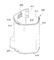
図4を参照して、天井補強板620の端部には係止片621が下方に向けてほぼ直角に折り曲げられており、これに対して、熱交換器200の前方管寄せ板210の上端角部には係止スリット211が設けられている。係止片621を係止スリット211に差し込むことにより、天井補強板620と熱交換器200とが連結される。
【0032】
図1を参照して、各熱交換器200の前方管寄せ板210には、雌ネジ穴212が例えば2箇所に設けられている。これに対応して、ファンリング600側にもネジ挿通孔602が穿設されており、ファンリング600側からネジ込まれる図示しない雄ネジにより、各熱交換器200がファンリング600にネジ止めされる。
【0033】
熱交換器200の後方管寄せ板220は、仕切り板400の開口部410にある端板411にネジ止めされる。ネジはいずれもタッピンネジであってよい。このようにして、熱交換器200,200、ファンリング600および仕切り板400が一体的に連結される。
【0034】
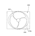
天井補強板620は、天面側からの荷重に対する強度向上ために設けられるが、本発明において、天井補強板620は別の役割を担っている。通常、プロペラファン553の送風性能上、ファンリング600のベルマウス610は環状に連続して形成される。
【0035】
これに反して、この実施形態では、室外機の高さ寸法を低くするため、図1およびファンリング600の正面図である図5に示すように、ベルマウス610の上側の一部分をカットし、そのカットされた部分を補完するため、天井補強板620にベルマウス610に連続する円弧状の補完凹部622を形成している。
【0036】
これにより、より大径のプロペラファン553を使用し、その送風性能を落とすことなく、室外機の高さ寸法を低くしてコンパクト化を図ることができる。図6の斜視図に、ベルマウス610の組み立て状態を示す。なお、室外機の高さ寸法をより低くするため、ベルマウス610の下側の一部分をもカットする必要がある場合には、ベース板100側にもベルマウス610に連続する円弧状の補完凹部を設ければよい。
【0037】
また、別の方法として、高さ寸法の制約などから、例えば天井補強板620自体を用いることができず、ベルマウス610の補完凹部622を形成できない場合には、図7に模式的に示すように、本来円形に形成されるベルマウス610を参照符号610aで示す楕円形に変更して、プロペラファン553とのクリアランスを調整することにより、空気吹出し方向の風速のバランスの均等化を図ることもできる。
【0038】
次に、図8を追加的に参照して、仕切り板400は、ベース板100から外胴700の天井面710までの高さにほぼ等しい高さを有し、その上端には上記天井面710を支持する上部フランジ412が形成されている。また、仕切り板400の下端側にも、ベース板100に対する設置安定性を得るための下部フランジ415が形成されている。
【0039】
この場合、上部フランジ412には、モータ支持台500の上端がネジ止めされる受け板413が連設されている。受け板413は、モータ支持台500に対する位置決め用の凹部414を備えている。なお、外胴700を被せる際、熱交換器200と同じく、上部フランジ412にもパッキング材が装着される。
【0040】
下部フランジ415には、ベース板100に対するネジ止め片420が形成されるが、好ましくは図9に例示するように、ネジ止め片420の一部分にベース板100側に向けて斜め下方に折り曲げられた位置決め兼ネジ止め用の係止片421を形成し、これに対応して、ベース板100側には、係止片421の相手方となる受け板120を形成するとよい。
【0041】
また、より正確な位置決めを行なうようにするため、ネジ止め片420に例えば菱形の位置決め孔422を穿設し、これに対応して、ベース板100側には、位置決め孔422内に嵌合する切り起こし舌片121を形成するとよい。
【0042】
図示されていないが、仕切り板400の内面には遮音材が設けられる。遮音材は樹脂塗膜や発泡樹脂シートであってよい。また、この実施形態においては、仕切り板400内の温度を適正に維持して圧縮機300の付属電気部品の長寿命化を図るため、仕切り板400の一部分には、放熱用のルーバー423が形成されている。
【0043】
この実施形態においては、圧縮機300の側方にアキュムレータ310が付設されているため、図2に例示されているように、仕切り板400は左側壁がフラットであるのに対して、アキュムレータ310が存在する右側壁側が出っ張る左右非対称形となっている。
【0044】
したがって、右側熱交換器200側の通風抵抗が左側熱交換器200の通風抵抗よりも高くなり、左右の熱交換器で吸込風量が異なることになる。そこで、本発明では、吸込風量が多い方の熱交換器側(この例では左側熱交換器200)の熱交換能力を吸込風量が少ない方の熱交換器側(この例では右側熱交換器200)の熱交換能力よりも大きく設定して、熱交換能力の適正化と低騒音化を図るようにしている。
【0045】
その一つの方法として、この実施形態では図2のように、冷媒配管を左側熱交換器200側では例えば2列(2パス)とし、右側熱交換器200側では例えば1列(1パス)としているが、別の方法として、熱交換器のフィンピッチもしくはフィン幅を異ならせてもよく、また、熱交換器のフィンに設けられるスリットもしくはルーバーの数や形状を異ならせるようにしてもよい。
【0046】
なお、この実施形態とは異なり、アキュムレータ310を圧縮機の背面側もしくは前面側に配置して、仕切り板400を左右対称形状とすることにより、左右の熱交換器200,200を通過する吸込風量がほぼ等しくなるため、各熱交換器に熱交換能力の等しい同一の熱交換器を用いることができる。したがって、その分、部品点数を削減できコスト低減が図れる。
【0047】
図10を追加的に参照して、モータ支持台500は仕切り板400の前面側に配置され、筐体の剛体化を図るため、仕切り板400とともに外胴700の天井面710を支持するように、その上端が仕切り板400の上端に固定され、下端側がベース板100に固定される。
【0048】
この実施形態において、モータ支持台500は梯子状に形成され、その中央部にファンモータ551の取付孔510を備えている。モータ支持台500の上部には、仕切り板400の受け板413に被せるようにして取り付けられる上枠520が設けられている。上枠520のほぼ中央には、受け板413の凹部414に嵌合する位置決め凹部521が形成されており、凹部414と凹部521とがタッピンネジによって固定される。
【0049】
また、モータ支持台500の側枠530には、ファンモータ551の振動を抑えるため、仕切り板400の前面に当接して同仕切り板400との間隔を一定に保つスペーサ531が設けられている。
【0050】
この場合、スペーサ531は、側枠530から一体に折り曲げられた板材からなるが、仕切り板400に対する振動伝達面を小さするため、図11に示すように、絞り加工による凸部532が形成されている。なお、図10には一方の側枠530側のスペーサ531しか示されていないが、他方の側枠530側にも同様に設けられている。
【0051】
また、モータ支持台500の下枠540には、ベース板100に対する固定フランジ541が連設されている。固定フランジ541は、ベース板100に対して広い面積で接触するように下枠540から前方に向けてほぼ直角に折り曲げられているとともに、モータ支持台500の幅よりも広幅となるように左右に広がる翼片542,542を備えている。
【0052】
モータ支持台500は、固定フランジ541およびその左右の翼片542,542を介してベース板100に対してネジ止めされ、これにより、ベース板100との一体化が図れ、ファンモータ551の振動がより効果的に抑えられる。
【0053】
先に説明したように、ベース板100の四隅には設置台に対する設置用脚部110(図3参照)が設けられているが、図12を参照して、ベース板100には設置用脚部110とは別に、圧縮機300の周りに、同ベース板100を下側に例えば断面半円状(樋状)に凹ませてなる圧縮機用支持脚130が少なくとも3箇所に設けられている。
【0054】
圧縮機用支持脚130は、圧縮機300の周りに同心円上に等間隔で配置されるとともに、その各々が平面視で圧縮機300を中心とする所定曲率の円弧状に形成されることが好ましい。圧縮機用支持脚130の高さは、設置用脚部110よりも低く、圧縮機300の重量によるベース板100の撓みにより設置台に接する高さに設定される。
【0055】
この圧縮機用支持脚130により、圧縮機300によるベース板100の振動が抑制され、また、仮にベース板100に搬送時などの落下衝撃により歪が生じたとしても、圧縮機100が傾いて設置されるおそれがなくなる。
【0056】
図13の背面側斜視図を参照して、電装品箱430と操作弁取付基板450は、仕切り板400の開口部410内に電装品箱430を上として縦一列に並ぶように装着されている。
【0057】
電装品箱430は、主な電気部品として、ターミナル(配線接続部)431、圧縮機用キャパシタ432およびファンモータ用キャパシタ433などを備えており、また、操作弁取付基板450には、二方操作弁451と三方操作弁452とが設けられている。
【0058】
本発明によると、二方操作弁451と三方操作弁452は、水平方向に所定の間隔をもって離された上で、三方操作弁452が上側に、そして二方操作弁451がそれよりも下側に配置され、これにより三方操作弁452のサービスバルブ付近をオープンにし、図示しないチャージホースを接続しやすくしている。なお、二方操作弁451の取付角度は三方操作弁452側に傾けることが好ましい。
【0059】
また、電装品箱430側については、ターミナル431が三方操作弁452側ではなく、二方操作弁451の上方に配置される。このような配置形態をとることにより、図14に示されているように、室内機と接続する接続配管CPの二方操作弁451と三方操作弁452とに対する接続作業が容易に行えるとともに、電気コードCAについても、三方操作弁452に接続される太管に邪魔されることなくターミナル431に容易に接続することが可能となる。
【0060】
次に、ファンリング600に取り付けられる吹出しグリル800について説明する。この室外機では、例えば図6に示されているように、吹出しグリル800のグリル中央部810を外側に向けて円弧状に膨出させ、その形状に合わせてプロペラファン533の翼後縁を延長することにより、送風性能の改善を図っている。なお、プロペラファン533の翼後縁とは、送風方向の下流側に位置する縁である。
【0061】
この実施形態において、プロペラファン533は3枚羽根であるが、図15(a)にその内の1枚を斜視図にて示し、そのA−A線に沿った螺旋方向の断面を図15(b)に示す。これらの図において、斜線部分がプロペラファン533の延長部分534であり、実際にこの延長部分534の螺旋方向に沿った幅W1を20mm(プロペラファンの軸線方向に沿った幅W2で16mm)として、延長部分のないプロペラファン(比較例)と送風性能を比較した。
【0062】
その結果、図16の風量−回転数の対比グラフから分かるように、同じ回転数では本発明例の方が風量80m3/h分増加しているが、図17の回転数−騒音の対比グラフからすると、騒音値は同じ回転数では本発明例の方が0.8dBだけ高い。しかしながら、図18の風量−騒音の対比グラフからすると、同じ風量で本発明例の方が騒音値は0.6dB低い。したがって、全体的評価では送風性能が改善されたと言える。
【0063】
【発明の効果】
以上説明したように、本発明によれば、その基本的な構成として、ほぼ矩形状に形成されたベース板の左右両側に、各一端側の一部分が背面側に回り込むようにほぼL字状に折り曲げられた左右一対の熱交換器を配置するとともに、ベース板の背面側のほぼ中央部に圧縮機を配置して、この圧縮機の周りを各熱交換器の背面側端部間に配置される開口部を有する仕切り板で囲い、この仕切り板の前面側にモータ支持台を介して送風機を配置するとともに、ベース板の前面側にファンリングを配置して、外胴をファンリングおよび熱交換器の上から被せて抑える一方で、仕切り板で外胴の天井面を支持し、仕切り板の開口部内に電装品箱と操作弁取付基板を装着するようにしたことにより、剛性が高い筐体構造を有するとともに、運転時の騒音・振動がともに少なく、しかも高性能でよりコンパクト化されたスプリット型エアコンの室外機が提供される。
【図面の簡単な説明】
【図1】本発明の実施形態に係る室外機の分解斜視図。
【図2】上記室外機の平面透視図。
【図3】上記室外機の側面透視図。
【図4】上記室外機に用いられる天井補強板と熱交換器の係止手段の構成を示した要部分解斜視図。
【図5】上記室外機に用いられるファンリングの正面図。
【図6】上記ファンリング周りの組み立て状態を示した斜視図。
【図7】上記ファンリングの変形例を模式的に示した正面図。
【図8】上記室外機に用いられる仕切り板を示した斜視図。
【図9】上記仕切り板の好適な位置決め要素を示した斜視図。
【図10】上記仕切り板にモータ支持台を取り付けた状態を示す斜視図。
【図11】上記モータ支持台が備える当接板の断面図。
【図12】圧縮機周りのベース基板に形成される圧縮機用支持脚を示した平面図。
【図13】上記仕切り板に電装品箱と操作弁取付基板を装着した状態を示す背面図。
【図14】配管および配線状態を示した図13と同様の背面図。
【図15】上記室外機に用いられるプロペラファンの好適例を示した斜視図およびその断面図。
【図16】上記プロペラファンの風量−回転数の対比グラフ。
【図17】上記プロペラファンの回転数−騒音の対比グラフ。
【図18】上記プロペラファンの風量−騒音の対比グラフ。
【図19】従来の室外機の内部配置構造を示した模式的平面図。
【符号の説明】
100 ベース板
110 設置用脚部
130 圧縮機用支持脚
200 熱交換器
210 前方管寄せ
220 後方管寄せ
300 圧縮機
310 アキュムレータ
400 仕切り板
410 開口部
430 電装品箱
431 ターミナル
450 操作弁取付基板
451 二方操作弁
452 三方操作弁
500 モータ支持台
510 モータ取付孔
520 上枠
530 側枠
531 スペーサ
540 下枠
541 固定フランジ
550 送風機
551 ファンモータ
553 プロペラファン
600 ファンリング
610 ベルマウス
620 天井補強板
621 係止片
622 補完凹部
700 外胴
710 天井面
800 吹出しグリル
810 グリル中央部[0001]
BACKGROUND OF THE INVENTION
The present invention relates to an outdoor unit of a split type air conditioner, and more particularly to an outdoor unit of a split type air conditioner that has a highly rigid casing structure, has less noise and vibration during operation, and can be made more compact. is there.
[0002]
[Prior art]
In a split type air conditioner (air conditioner), an indoor unit and an outdoor unit are connected via a pipe, and the outdoor unit is installed outdoors, for example, in a garden, on a veranda, or on a roof. FIG. 19 schematically shows the internal structure of a general outdoor unit in plan view.
[0003]
Usually, an outdoor unit is provided with a box-
[0004]
For this reason, the compressor 4 is installed at the corner of the
[0005]
[Problems to be solved by the invention]
However, such component arrangement has the following problems. First, the casing is weak and easily deformed with respect to the load from the ceiling surface side. Since no partition plate is provided around the compressor, noise tends to go out during operation.
[0006]
Also, since the blower fan is mainly supported on the base plate side of the housing, vibration during operation is amplified by the base plate and then transmitted to the entire housing. appear. In addition, for example, when the base plate is deformed due to a drop impact during transportation, the compressor may be tilted and installed and operated as it is.
[0007]
Since the compressor is arranged at the corner of the casing, the center of gravity of the outdoor unit is biased. In other words, it is difficult to carry because the weight balance is poor, and it imposes an extra burden on the operator, especially when lifting to a high place with a ladder or the like.
[0008]
In addition, since there is one heat exchanger and an L-shaped arrangement, there is a limit to downsizing without reducing performance. Therefore, for example, when a split-type air conditioner is replaced with an integrated air conditioner that has been used up to now, the outdoor unit is installed on an existing installation stand that is designed to project from the wall hole to the outdoor side for installation of the integrated air conditioner. However, since the conventional outdoor unit is too large, there was an inconvenience that the existing installation base had to be modified.
[0009]
The present invention has been made in order to solve such problems, and its purpose is to have a highly rigid housing structure, reduce noise and vibration during operation, and achieve high performance and compactness. It is to provide an outdoor unit of a split type air conditioner.
[0010]
[Means for Solving the Problems]
In order to achieve the above object, an outdoor unit of a split type air conditioner according to the present invention is provided with a base plate formed in a substantially rectangular shape and on both the left and right sides of the base plate, and a part of each one end side wraps around the back side approximately mounting the L-shape bent pair of heat exchangers, a compressor provided in the substantially central portion of the rear side of the base plate, to the base plate on to surround the periphery of the compressor Covering the partition plate, the blower attached to the front side of the partition plate via a motor support, the fan ring disposed on the front side of the base plate, the fan ring and the heat exchanger An outer cylinder fixed to the base plate, and the partition plate has a height substantially equal to a height from the base plate to the ceiling surface of the outer cylinder, and a rear side end of each heat exchanger. Placed between Has an opening, it is characterized in that the operating valve mounting board and the electrical component box along the opening surface of the opening portion is disposed.
[0011]
In this way, the compressor and the blower are arranged in the approximate center of the base plate, the two heat exchangers are arranged symmetrically on both sides thereof, and the fan ring and both heat exchangers are fixed by the outer cylinder. By doing so, the rigidity of the casing is increased, and the overall weight balance is good, and it is possible to design a compact while maintaining high performance. Further, since a partition plate is provided around the compressor, the noise is low.
[0012]
Further, in the present invention, the upper Symbol partition plate, with a height substantially equal to the height from the base plate to the ceiling surface of the outer cylinder, are arranged between the rear side end portion of each heat exchanger By having an opening and arranging the electrical component box and operation valve mounting board along the opening surface of the opening , the rigidity of the housing can be further increased and further noise reduction is possible. It becomes.
[0013]
Furthermore, in order to make the casing rigid, it is preferable to provide a ceiling reinforcing plate provided with a locking means for the heat exchanger on the upper part of the fan ring. Also, an upper flange may be formed at the upper end of the partition plate to support the ceiling surface of the outer trunk.
[0014]
Also, from the viewpoint of assembly workability, a locking piece for positioning and screwing that is bent obliquely downward toward the base plate side is provided on the lower end side of the partition plate, and the locking piece is screwed to the base plate side. It is preferable to form a receiving plate.
[0015]
In order to enhance the sound insulation effect, a sound insulation material may be provided on the inner surface of the partition plate. Moreover, the lifetime of the electrical components around a compressor can be lengthened by forming the louver for heat dissipation in a part of the partition plate.
[0016]
By making the partition plate a symmetrical shape, the amount of air sucked into the housing becomes substantially equal on the left and right, so the same heat exchanger can be used for the two heat exchangers. That is, the heat exchanger can be shared.
[0017]
In order to make the housing rigid, it is preferable that the motor support base is fixed to the upper end of the partition plate and the lower end side is fixed to the base plate so as to support the ceiling surface of the outer trunk together with the partition plate.
[0018]
According to a preferred aspect of the present invention, in order to suppress vibration of the blower, a spacer is provided on the motor support so as to contact the partition plate and keep a constant distance from the partition plate. The spacer is made of a plate material bent integrally from the motor support base, but the vibration transmitting surface can be made small by forming a convex portion by drawing on the contact surface with the partition plate.
[0019]
Also, a fixed flange that is wider than the motor support base is connected to the lower end of the motor support base that is fixed to the base plate so that it can be integrated with the base plate. Can be suppressed.
[0020]
In addition to the installation legs for the installation bases provided at the four corners of the base plate, at least three support legs for the compressor are provided around the compressor with the base plate recessed downward. This is also a feature of the present invention, in which the compressor vibration is damped by its support legs.
[0021]
The support legs for the compressor are lower than the installation legs, and are preferably in contact with the installation base due to the deflection of the base plate due to the weight of the compressor. Even if distortion occurs due to impact, there is no risk that the compressor will be installed at an angle. More preferably, the support legs for the compressor are arranged concentrically around the compressor at equal intervals, and are formed in an arc shape having a predetermined curvature centered on the compressor.
[0022]
Further, according to a preferred aspect of the present invention, in order to facilitate piping and electrical wiring work, the electrical component box is on the upper side, and the operation valve mounting board is disposed on the lower side thereof. In a state where the two operation valves, the operation valve and the three-way operation valve, are separated from each other in the horizontal direction at a predetermined interval, the three-way operation valve is disposed at an upper position than the two-way operation valve. Moreover, the wiring connection part in the electrical component box is disposed above the two-way operation valve.
[0023]
If the partition plate is asymmetrical and the suction air volume is different between the left and right heat exchangers, the heat exchange capacity on the heat exchanger side with the larger suction air volume is the heat exchange on the heat exchanger side with the smaller suction air volume. It is preferable to set larger than the capacity.
[0024]
The method may be based on the number of rows of refrigerant piping, the fin pitch or fin width of the heat exchanger, or the slit or louver provided on the fin of the heat exchanger.
[0025]
DETAILED DESCRIPTION OF THE INVENTION
Next, an embodiment of the present invention will be described. First, basic components included in the outdoor unit according to this embodiment will be described with reference to an exploded perspective view of FIG. 1, a plan perspective view of FIG. 2, and a side perspective view of FIG. 3.
[0026]
This outdoor unit includes a
[0027]
Each
[0028]
A
[0029]
In the
[0030]
On the front side of the
[0031]
Referring to FIG. 4, a
[0032]
Referring to FIG. 1, female screw holes 212 are provided in, for example, two locations in the
[0033]
The
[0034]
The
[0035]
On the other hand, in this embodiment, in order to reduce the height dimension of the outdoor unit, as shown in FIG. 5 which is a front view of FIG. 1 and the
[0036]
As a result, the
[0037]
As another method, for example, when the
[0038]
Next, referring additionally to FIG. 8, the
[0039]
In this case, the
[0040]
The
[0041]
In order to perform more accurate positioning, for example, a diamond-shaped
[0042]
Although not shown, a sound insulating material is provided on the inner surface of the
[0043]
In this embodiment, since the
[0044]
Therefore, the ventilation resistance on the right
[0045]
As one of the methods, in this embodiment, as shown in FIG. 2, the refrigerant piping is, for example, in two rows (two passes) on the
[0046]
Unlike this embodiment, the
[0047]
Referring additionally to FIG. 10, the
[0048]
In this embodiment, the
[0049]
Further, the
[0050]
In this case, the
[0051]
A fixing
[0052]
The
[0053]
As described above, installation legs 110 (see FIG. 3) for the installation table are provided at the four corners of the
[0054]
The
[0055]
The
[0056]
With reference to the rear perspective view of FIG. 13, the
[0057]
The
[0058]
According to the present invention, the two-
[0059]
Further, on the
[0060]
Next, the blowing
[0061]
In this embodiment, the
[0062]
As a result, as can be seen from the air volume-rotation speed comparison graph of FIG. 16, the example of the present invention increases the air volume by 80 m 3 / h at the same rotation speed, but the rotation speed-noise comparison graph of FIG. Therefore, the noise value is higher by 0.8 dB in the example of the present invention at the same rotational speed. However, according to the air volume-noise comparison graph of FIG. 18, the noise value of the present invention is 0.6 dB lower at the same air volume. Therefore, it can be said that the ventilation performance was improved in the overall evaluation.
[0063]
【The invention's effect】
As described above, according to the present invention, as a basic configuration, the left and right sides of the base plate formed in a substantially rectangular shape are substantially L-shaped so that a part of each one end side wraps around the back side. A pair of bent left and right heat exchangers are arranged, and a compressor is arranged at the central part on the back side of the base plate, and the periphery of this compressor is arranged between the back side ends of each heat exchanger. The fan is placed on the front side of the base plate, and the fan ring is placed on the front side of the base plate, and the outer body is fanned and heat exchanged. Highly rigid housing by supporting the ceiling surface of the outer trunk with a partition plate and mounting the electrical component box and operation valve mounting board in the opening of the partition plate Structure and noise during operation Vibration both reduced, yet more compacted split type air conditioner outdoor unit is provided with high performance.
[Brief description of the drawings]
FIG. 1 is an exploded perspective view of an outdoor unit according to an embodiment of the present invention.
FIG. 2 is a plan perspective view of the outdoor unit.
FIG. 3 is a side perspective view of the outdoor unit.
FIG. 4 is an exploded perspective view of a main part showing a configuration of a ceiling reinforcing plate and a heat exchanger locking means used in the outdoor unit.
FIG. 5 is a front view of a fan ring used in the outdoor unit.
6 is a perspective view showing an assembled state around the fan ring. FIG.
FIG. 7 is a front view schematically showing a modification of the fan ring.
FIG. 8 is a perspective view showing a partition plate used in the outdoor unit.
FIG. 9 is a perspective view showing a suitable positioning element of the partition plate.
FIG. 10 is a perspective view showing a state where a motor support is attached to the partition plate.
FIG. 11 is a cross-sectional view of a contact plate provided in the motor support.
FIG. 12 is a plan view showing compressor support legs formed on a base substrate around the compressor.
FIG. 13 is a rear view showing a state where an electrical component box and an operation valve mounting board are mounted on the partition plate.
14 is a rear view similar to FIG. 13, showing the piping and wiring state.
FIG. 15 is a perspective view and a cross-sectional view showing a preferred example of a propeller fan used in the outdoor unit.
FIG. 16 is a graph of the air volume vs. rotation speed of the propeller fan.
FIG. 17 is a graph of the rotation speed-noise of the propeller fan.
FIG. 18 is an air volume-noise comparison graph of the propeller fan.
FIG. 19 is a schematic plan view showing an internal arrangement structure of a conventional outdoor unit.
[Explanation of symbols]
100
Claims (6)
上記仕切り板は、上記ベース板から上記外胴の天井面までの高さにほぼ等しい高さであるとともに、上記各熱交換器の背面側端部間に配置される開口部を有し、上記開口部の開口面に沿って電装品箱と操作弁取付基板とが配置されていることを特徴とするスプリット型エアコンの室外機。A base plate formed in a substantially rectangular shape, a pair of left and right heat exchangers arranged on both the left and right sides of the base plate and bent in a substantially L shape so that a part of each one end side wraps around the back side; via a compressor provided in the substantially central portion of the rear side of the base plate, and a partition plate attached to the base board so as to surround the periphery of the compressor, the motor support table on the front side of the partition plate A fan mounted on the front side of the base plate, and an outer body that covers the fan ring and the heat exchanger and is fixed to the base plate .
The partition plate has a height that is substantially equal to a height from the base plate to the ceiling surface of the outer body, and has an opening that is disposed between rear side end portions of the heat exchangers. An outdoor unit for a split type air conditioner, wherein an electrical component box and an operation valve mounting board are arranged along an opening surface of the opening .
Priority Applications (6)
| Application Number | Priority Date | Filing Date | Title |
|---|---|---|---|
| JP2001067286A JP4671007B2 (en) | 2001-03-09 | 2001-03-09 | Split air conditioner outdoor unit |
| ARP020100836A AR032966A1 (en) | 2001-03-09 | 2002-03-07 | AN OUTDOOR UNIT OF A SPLIT TYPE AIR CONDITIONING EQUIPMENT |
| TW91104409A TW513545B (en) | 2001-03-09 | 2002-03-08 | Outdoor unit of a split type air conditioner |
| CN 02107019 CN1228575C (en) | 2001-03-09 | 2002-03-08 | Outdoor machine of separating air conditioner |
| BR0200735A BR0200735A (en) | 2001-03-09 | 2002-03-11 | Outdoor unit of a split type air conditioner |
| HK03100689.3A HK1048657A1 (en) | 2001-03-09 | 2003-01-27 | Outdoor unit of a split type air conditioner |
Applications Claiming Priority (1)
| Application Number | Priority Date | Filing Date | Title |
|---|---|---|---|
| JP2001067286A JP4671007B2 (en) | 2001-03-09 | 2001-03-09 | Split air conditioner outdoor unit |
Publications (2)
| Publication Number | Publication Date |
|---|---|
| JP2002267209A JP2002267209A (en) | 2002-09-18 |
| JP4671007B2 true JP4671007B2 (en) | 2011-04-13 |
Family
ID=18925663
Family Applications (1)
| Application Number | Title | Priority Date | Filing Date |
|---|---|---|---|
| JP2001067286A Expired - Fee Related JP4671007B2 (en) | 2001-03-09 | 2001-03-09 | Split air conditioner outdoor unit |
Country Status (6)
| Country | Link |
|---|---|
| JP (1) | JP4671007B2 (en) |
| CN (1) | CN1228575C (en) |
| AR (1) | AR032966A1 (en) |
| BR (1) | BR0200735A (en) |
| HK (1) | HK1048657A1 (en) |
| TW (1) | TW513545B (en) |
Families Citing this family (21)
| Publication number | Priority date | Publication date | Assignee | Title |
|---|---|---|---|---|
| CN100414202C (en) * | 2004-04-30 | 2008-08-27 | 乐金电子(天津)电器有限公司 | Air-conditioner outdoor set equipped with operation valve assembly |
| KR20050112234A (en) * | 2004-05-25 | 2005-11-30 | 삼성전자주식회사 | Outdoor unit of air conditioner |
| JP4521867B2 (en) * | 2004-10-19 | 2010-08-11 | 日立アプライアンス株式会社 | Air conditioner outdoor unit |
| CN100455922C (en) * | 2004-11-29 | 2009-01-28 | 乐金电子(天津)电器有限公司 | Outdoor unit of one dragging more ceiling air conditioner |
| WO2007091826A2 (en) * | 2006-02-08 | 2007-08-16 | Lg Electronics Inc. | Outdoor unit of air conditioner and blower of outdoor unit |
| JP2008121948A (en) * | 2006-11-10 | 2008-05-29 | Matsushita Electric Ind Co Ltd | Outdoor unit of air conditioner |
| CA2686078C (en) * | 2006-12-15 | 2019-02-19 | Voyage-Air Guitar | Travel stringed instrument system |
| JP2008267731A (en) * | 2007-04-23 | 2008-11-06 | Mitsubishi Electric Corp | Air-conditioning device |
| US20100251753A1 (en) * | 2007-06-22 | 2010-10-07 | Ole Thogersen | Refrigerating container for land, road and rail vehicles |
| JP2010029394A (en) * | 2008-07-28 | 2010-02-12 | Toshiba Electric Appliance Co Ltd | Beverage dispenser device |
| JP2010144990A (en) * | 2008-12-18 | 2010-07-01 | Panasonic Corp | Outdoor unit of air conditioner |
| JP5115540B2 (en) * | 2009-11-18 | 2013-01-09 | ダイキン工業株式会社 | Air conditioner outdoor unit |
| CN104279648A (en) * | 2013-07-09 | 2015-01-14 | 珠海格力电器股份有限公司 | Stop valve installation plate and air conditioner outdoor unit |
| CN103884131B (en) * | 2014-03-20 | 2016-05-11 | 陈万仁 | The wind source heat pump system of four side return air lateral orientation air-supplies |
| CN104456761A (en) * | 2014-12-24 | 2015-03-25 | 海信科龙电器股份有限公司 | Air conditioner outdoor unit and air conditioner |
| JP6475040B2 (en) * | 2015-02-25 | 2019-02-27 | シャープ株式会社 | Air conditioner outdoor unit |
| KR101872567B1 (en) | 2015-08-25 | 2018-06-28 | 엘지전자 주식회사 | An outdoor unit for a an air conditioner |
| EP3385626B1 (en) * | 2015-12-04 | 2022-10-26 | Mitsubishi Electric Corporation | Outdoor machine |
| CN106500201A (en) * | 2016-12-08 | 2017-03-15 | 广东欧科空调制冷有限公司 | The outer machine of compact ceiling type air conditioner |
| CN108731125A (en) * | 2018-06-25 | 2018-11-02 | 格力电器(石家庄)有限公司 | A kind of air-conditioning and outdoor unit |
| CN115917217A (en) * | 2020-09-08 | 2023-04-04 | 三菱电机株式会社 | Outdoor machine |
Citations (13)
| Publication number | Priority date | Publication date | Assignee | Title |
|---|---|---|---|---|
| JPH0369305U (en) * | 1990-10-26 | 1991-07-10 | ||
| JPH0650568A (en) * | 1992-07-30 | 1994-02-22 | Toshiba Corp | Air conditioner |
| JPH07198170A (en) * | 1994-01-07 | 1995-08-01 | Mitsubishi Heavy Ind Ltd | Outdoor unit for air conditioner |
| JPH0886474A (en) * | 1994-09-16 | 1996-04-02 | Hitachi Ltd | Outdoor machine of air conditioner |
| JPH08178366A (en) * | 1994-12-21 | 1996-07-12 | Sharp Corp | Heat exchanger |
| JPH08219492A (en) * | 1995-02-08 | 1996-08-30 | Fujitsu General Ltd | Outdoor device of air conditioner |
| JPH08313005A (en) * | 1995-05-18 | 1996-11-29 | Mitsubishi Heavy Ind Ltd | Outdoor unit of air conditioner |
| JPH09189462A (en) * | 1996-01-08 | 1997-07-22 | Mitsubishi Electric Corp | Air conditioning device |
| JPH09250780A (en) * | 1996-03-19 | 1997-09-22 | Fujitsu General Ltd | Outdoor equipment of air conditioner |
| JPH11148684A (en) * | 1997-11-20 | 1999-06-02 | Fujitsu General Ltd | Outdoor machine for air conditioner |
| JP2000111102A (en) * | 1998-09-30 | 2000-04-18 | Toshiba Corp | Outdoor unit for air conditioner |
| JP2000234886A (en) * | 1999-02-17 | 2000-08-29 | Matsushita Electric Ind Co Ltd | Finned heat exchanger |
| JP2001033064A (en) * | 1999-07-22 | 2001-02-09 | Sanyo Electric Co Ltd | Outdoor unit for air conditioner |
-
2001
- 2001-03-09 JP JP2001067286A patent/JP4671007B2/en not_active Expired - Fee Related
-
2002
- 2002-03-07 AR ARP020100836A patent/AR032966A1/en not_active Application Discontinuation
- 2002-03-08 TW TW91104409A patent/TW513545B/en not_active IP Right Cessation
- 2002-03-08 CN CN 02107019 patent/CN1228575C/en not_active Expired - Fee Related
- 2002-03-11 BR BR0200735A patent/BR0200735A/en not_active Application Discontinuation
-
2003
- 2003-01-27 HK HK03100689.3A patent/HK1048657A1/en unknown
Patent Citations (13)
| Publication number | Priority date | Publication date | Assignee | Title |
|---|---|---|---|---|
| JPH0369305U (en) * | 1990-10-26 | 1991-07-10 | ||
| JPH0650568A (en) * | 1992-07-30 | 1994-02-22 | Toshiba Corp | Air conditioner |
| JPH07198170A (en) * | 1994-01-07 | 1995-08-01 | Mitsubishi Heavy Ind Ltd | Outdoor unit for air conditioner |
| JPH0886474A (en) * | 1994-09-16 | 1996-04-02 | Hitachi Ltd | Outdoor machine of air conditioner |
| JPH08178366A (en) * | 1994-12-21 | 1996-07-12 | Sharp Corp | Heat exchanger |
| JPH08219492A (en) * | 1995-02-08 | 1996-08-30 | Fujitsu General Ltd | Outdoor device of air conditioner |
| JPH08313005A (en) * | 1995-05-18 | 1996-11-29 | Mitsubishi Heavy Ind Ltd | Outdoor unit of air conditioner |
| JPH09189462A (en) * | 1996-01-08 | 1997-07-22 | Mitsubishi Electric Corp | Air conditioning device |
| JPH09250780A (en) * | 1996-03-19 | 1997-09-22 | Fujitsu General Ltd | Outdoor equipment of air conditioner |
| JPH11148684A (en) * | 1997-11-20 | 1999-06-02 | Fujitsu General Ltd | Outdoor machine for air conditioner |
| JP2000111102A (en) * | 1998-09-30 | 2000-04-18 | Toshiba Corp | Outdoor unit for air conditioner |
| JP2000234886A (en) * | 1999-02-17 | 2000-08-29 | Matsushita Electric Ind Co Ltd | Finned heat exchanger |
| JP2001033064A (en) * | 1999-07-22 | 2001-02-09 | Sanyo Electric Co Ltd | Outdoor unit for air conditioner |
Also Published As
| Publication number | Publication date |
|---|---|
| CN1374483A (en) | 2002-10-16 |
| JP2002267209A (en) | 2002-09-18 |
| TW513545B (en) | 2002-12-11 |
| CN1228575C (en) | 2005-11-23 |
| AR032966A1 (en) | 2003-12-03 |
| BR0200735A (en) | 2003-01-07 |
| HK1048657A1 (en) | 2003-04-11 |
Similar Documents
| Publication | Publication Date | Title |
|---|---|---|
| JP4671007B2 (en) | Split air conditioner outdoor unit | |
| JP4623253B2 (en) | Split air conditioner outdoor unit | |
| CN106765654B (en) | Air conditioner | |
| JP6488886B2 (en) | Duct type air conditioner | |
| EP1050720B1 (en) | Air conditioner | |
| JPWO2006068210A1 (en) | Air conditioner outdoor unit | |
| US11480346B2 (en) | Air conditioner | |
| US20170248330A1 (en) | Outdoor unit of air conditioner | |
| US6877331B2 (en) | Air conditioner | |
| JP4555712B2 (en) | Air conditioner outdoor unit | |
| JP5496697B2 (en) | Air conditioner outdoor unit | |
| JP2008267727A (en) | Refrigerating air conditioner | |
| JP3315317B2 (en) | Air conditioner | |
| JPH10153192A (en) | Turbo fan and ceiling arrangement type air conditioner mounted it | |
| WO2016208567A1 (en) | Ceiling installation type air conditioner and heat exchanger | |
| JP2003202119A (en) | Air conditioner | |
| JP5128221B2 (en) | Indoor heat exchanger and air conditioner | |
| JP3106628B2 (en) | Outdoor unit of air conditioner | |
| JP3009047U (en) | Air conditioner outdoor unit | |
| JP5755166B2 (en) | Blower | |
| JP3846403B2 (en) | Air conditioner outdoor unit | |
| CN216620016U (en) | Wall-mounted air conditioner | |
| JP3009045U (en) | Air conditioner outdoor unit | |
| JP4915100B2 (en) | Air conditioner indoor unit | |
| JP3009046U (en) | Air conditioner outdoor unit |
Legal Events
| Date | Code | Title | Description |
|---|---|---|---|
| A621 | Written request for application examination |
Free format text: JAPANESE INTERMEDIATE CODE: A621 Effective date: 20070731 |
|
| A977 | Report on retrieval |
Free format text: JAPANESE INTERMEDIATE CODE: A971007 Effective date: 20100624 |
|
| A131 | Notification of reasons for refusal |
Free format text: JAPANESE INTERMEDIATE CODE: A131 Effective date: 20100811 |
|
| A521 | Written amendment |
Free format text: JAPANESE INTERMEDIATE CODE: A523 Effective date: 20101008 |
|
| TRDD | Decision of grant or rejection written | ||
| A01 | Written decision to grant a patent or to grant a registration (utility model) |
Free format text: JAPANESE INTERMEDIATE CODE: A01 Effective date: 20101222 |
|
| A01 | Written decision to grant a patent or to grant a registration (utility model) |
Free format text: JAPANESE INTERMEDIATE CODE: A01 |
|
| A61 | First payment of annual fees (during grant procedure) |
Free format text: JAPANESE INTERMEDIATE CODE: A61 Effective date: 20110104 |
|
| FPAY | Renewal fee payment (event date is renewal date of database) |
Free format text: PAYMENT UNTIL: 20140128 Year of fee payment: 3 |
|
| LAPS | Cancellation because of no payment of annual fees |