EP1867904B1 - Sealing device for wall lead-throughs, pipes and ducts - Google Patents
Sealing device for wall lead-throughs, pipes and ducts Download PDFInfo
- Publication number
- EP1867904B1 EP1867904B1 EP06017206A EP06017206A EP1867904B1 EP 1867904 B1 EP1867904 B1 EP 1867904B1 EP 06017206 A EP06017206 A EP 06017206A EP 06017206 A EP06017206 A EP 06017206A EP 1867904 B1 EP1867904 B1 EP 1867904B1
- Authority
- EP
- European Patent Office
- Prior art keywords
- sealing
- media
- flat tubular
- valve
- tubular pad
- Prior art date
- Legal status (The legal status is an assumption and is not a legal conclusion. Google has not performed a legal analysis and makes no representation as to the accuracy of the status listed.)
- Not-in-force
Links
- 238000007789 sealing Methods 0.000 title claims description 170
- 239000004033 plastic Substances 0.000 claims description 37
- 229920003023 plastic Polymers 0.000 claims description 37
- 239000002184 metal Substances 0.000 claims description 33
- 239000007788 liquid Substances 0.000 claims description 15
- 238000000034 method Methods 0.000 claims description 14
- 239000000463 material Substances 0.000 claims description 11
- 238000003466 welding Methods 0.000 claims description 11
- 239000000203 mixture Substances 0.000 claims description 10
- 230000008569 process Effects 0.000 claims description 8
- XLYOFNOQVPJJNP-UHFFFAOYSA-N water Substances O XLYOFNOQVPJJNP-UHFFFAOYSA-N 0.000 claims description 8
- 239000000853 adhesive Substances 0.000 claims description 7
- 230000001070 adhesive effect Effects 0.000 claims description 7
- 239000004814 polyurethane Substances 0.000 claims description 7
- 239000012209 synthetic fiber Substances 0.000 claims description 6
- 229920002994 synthetic fiber Polymers 0.000 claims description 6
- 239000006260 foam Substances 0.000 claims description 5
- 239000004264 Petrolatum Substances 0.000 claims description 4
- 229940066842 petrolatum Drugs 0.000 claims description 4
- 238000004804 winding Methods 0.000 claims description 4
- 239000006004 Quartz sand Substances 0.000 claims description 3
- VYPSYNLAJGMNEJ-UHFFFAOYSA-N Silicium dioxide Chemical compound O=[Si]=O VYPSYNLAJGMNEJ-UHFFFAOYSA-N 0.000 claims description 3
- 239000010426 asphalt Substances 0.000 claims description 3
- 239000008187 granular material Substances 0.000 claims description 3
- 238000012423 maintenance Methods 0.000 claims description 2
- 235000019271 petrolatum Nutrition 0.000 claims description 2
- 238000004079 fireproofing Methods 0.000 claims 11
- 239000000758 substrate Substances 0.000 claims 4
- 239000011796 hollow space material Substances 0.000 claims 3
- 229920000642 polymer Polymers 0.000 claims 3
- 239000000945 filler Substances 0.000 claims 2
- 239000010454 slate Substances 0.000 claims 2
- 244000025254 Cannabis sativa Species 0.000 claims 1
- 235000012766 Cannabis sativa ssp. sativa var. sativa Nutrition 0.000 claims 1
- 235000012765 Cannabis sativa ssp. sativa var. spontanea Nutrition 0.000 claims 1
- 229920000742 Cotton Polymers 0.000 claims 1
- 239000000654 additive Substances 0.000 claims 1
- 235000009120 camo Nutrition 0.000 claims 1
- 235000005607 chanvre indien Nutrition 0.000 claims 1
- 239000011248 coating agent Substances 0.000 claims 1
- 238000000576 coating method Methods 0.000 claims 1
- 239000011487 hemp Substances 0.000 claims 1
- 239000002245 particle Substances 0.000 claims 1
- 230000002093 peripheral effect Effects 0.000 claims 1
- 239000006223 plastic coating Substances 0.000 claims 1
- 229920000728 polyester Polymers 0.000 claims 1
- 229920001296 polysiloxane Polymers 0.000 claims 1
- 229920002635 polyurethane Polymers 0.000 claims 1
- 239000002699 waste material Substances 0.000 claims 1
- 239000002759 woven fabric Substances 0.000 claims 1
- 238000005192 partition Methods 0.000 description 14
- 239000002131 composite material Substances 0.000 description 13
- 239000007789 gas Substances 0.000 description 12
- 239000010408 film Substances 0.000 description 11
- 238000010276 construction Methods 0.000 description 6
- 238000013461 design Methods 0.000 description 6
- 239000003063 flame retardant Substances 0.000 description 5
- RNFJDJUURJAICM-UHFFFAOYSA-N 2,2,4,4,6,6-hexaphenoxy-1,3,5-triaza-2$l^{5},4$l^{5},6$l^{5}-triphosphacyclohexa-1,3,5-triene Chemical compound N=1P(OC=2C=CC=CC=2)(OC=2C=CC=CC=2)=NP(OC=2C=CC=CC=2)(OC=2C=CC=CC=2)=NP=1(OC=1C=CC=CC=1)OC1=CC=CC=C1 RNFJDJUURJAICM-UHFFFAOYSA-N 0.000 description 4
- 238000005452 bending Methods 0.000 description 4
- 230000006835 compression Effects 0.000 description 4
- 238000007906 compression Methods 0.000 description 4
- 238000003825 pressing Methods 0.000 description 4
- 239000011888 foil Substances 0.000 description 3
- 230000009467 reduction Effects 0.000 description 3
- 239000000523 sample Substances 0.000 description 3
- 239000003566 sealing material Substances 0.000 description 3
- 239000000126 substance Substances 0.000 description 3
- 206010053648 Vascular occlusion Diseases 0.000 description 2
- 230000004888 barrier function Effects 0.000 description 2
- 229920005601 base polymer Polymers 0.000 description 2
- 230000008901 benefit Effects 0.000 description 2
- 239000002775 capsule Substances 0.000 description 2
- 150000001875 compounds Chemical class 0.000 description 2
- 238000009826 distribution Methods 0.000 description 2
- 239000002689 soil Substances 0.000 description 2
- 238000003860 storage Methods 0.000 description 2
- 229940099259 vaseline Drugs 0.000 description 2
- 241000196324 Embryophyta Species 0.000 description 1
- 241000209035 Ilex Species 0.000 description 1
- 244000089486 Phragmites australis subsp australis Species 0.000 description 1
- 229920005830 Polyurethane Foam Polymers 0.000 description 1
- 239000003570 air Substances 0.000 description 1
- 230000005540 biological transmission Effects 0.000 description 1
- 230000008859 change Effects 0.000 description 1
- 239000003795 chemical substances by application Substances 0.000 description 1
- 239000013039 cover film Substances 0.000 description 1
- 230000007423 decrease Effects 0.000 description 1
- 238000009792 diffusion process Methods 0.000 description 1
- 238000007599 discharging Methods 0.000 description 1
- 239000013013 elastic material Substances 0.000 description 1
- 238000005538 encapsulation Methods 0.000 description 1
- 238000005516 engineering process Methods 0.000 description 1
- 230000007613 environmental effect Effects 0.000 description 1
- 239000000835 fiber Substances 0.000 description 1
- 230000009970 fire resistant effect Effects 0.000 description 1
- 229920002457 flexible plastic Polymers 0.000 description 1
- 235000013312 flour Nutrition 0.000 description 1
- 238000005187 foaming Methods 0.000 description 1
- 238000010438 heat treatment Methods 0.000 description 1
- 239000001307 helium Substances 0.000 description 1
- 229910052734 helium Inorganic materials 0.000 description 1
- SWQJXJOGLNCZEY-UHFFFAOYSA-N helium atom Chemical compound [He] SWQJXJOGLNCZEY-UHFFFAOYSA-N 0.000 description 1
- 239000002650 laminated plastic Substances 0.000 description 1
- 230000035515 penetration Effects 0.000 description 1
- 239000011496 polyurethane foam Substances 0.000 description 1
- 239000000843 powder Substances 0.000 description 1
- 239000010734 process oil Substances 0.000 description 1
- 239000011435 rock Chemical group 0.000 description 1
- 238000010008 shearing Methods 0.000 description 1
- 238000005382 thermal cycling Methods 0.000 description 1
- 238000012546 transfer Methods 0.000 description 1
- 238000009827 uniform distribution Methods 0.000 description 1
- 238000013022 venting Methods 0.000 description 1
Images


Classifications
-
- F—MECHANICAL ENGINEERING; LIGHTING; HEATING; WEAPONS; BLASTING
- F16—ENGINEERING ELEMENTS AND UNITS; GENERAL MEASURES FOR PRODUCING AND MAINTAINING EFFECTIVE FUNCTIONING OF MACHINES OR INSTALLATIONS; THERMAL INSULATION IN GENERAL
- F16L—PIPES; JOINTS OR FITTINGS FOR PIPES; SUPPORTS FOR PIPES, CABLES OR PROTECTIVE TUBING; MEANS FOR THERMAL INSULATION IN GENERAL
- F16L5/00—Devices for use where pipes, cables or protective tubing pass through walls or partitions
- F16L5/02—Sealing
- F16L5/10—Sealing by using sealing rings or sleeves only
-
- F—MECHANICAL ENGINEERING; LIGHTING; HEATING; WEAPONS; BLASTING
- F16—ENGINEERING ELEMENTS AND UNITS; GENERAL MEASURES FOR PRODUCING AND MAINTAINING EFFECTIVE FUNCTIONING OF MACHINES OR INSTALLATIONS; THERMAL INSULATION IN GENERAL
- F16L—PIPES; JOINTS OR FITTINGS FOR PIPES; SUPPORTS FOR PIPES, CABLES OR PROTECTIVE TUBING; MEANS FOR THERMAL INSULATION IN GENERAL
- F16L59/00—Thermal insulation in general
- F16L59/10—Bandages or covers for the protection of the insulation, e.g. against the influence of the environment or against mechanical damage
-
- F—MECHANICAL ENGINEERING; LIGHTING; HEATING; WEAPONS; BLASTING
- F16—ENGINEERING ELEMENTS AND UNITS; GENERAL MEASURES FOR PRODUCING AND MAINTAINING EFFECTIVE FUNCTIONING OF MACHINES OR INSTALLATIONS; THERMAL INSULATION IN GENERAL
- F16L—PIPES; JOINTS OR FITTINGS FOR PIPES; SUPPORTS FOR PIPES, CABLES OR PROTECTIVE TUBING; MEANS FOR THERMAL INSULATION IN GENERAL
- F16L7/00—Supporting pipes or cables inside other pipes or sleeves, e.g. for enabling pipes or cables to be inserted or withdrawn from under roads or railways without interruption of traffic
- F16L7/02—Supporting pipes or cables inside other pipes or sleeves, e.g. for enabling pipes or cables to be inserted or withdrawn from under roads or railways without interruption of traffic and sealing the pipes or cables inside the other pipes, cables or sleeves
-
- H—ELECTRICITY
- H02—GENERATION; CONVERSION OR DISTRIBUTION OF ELECTRIC POWER
- H02G—INSTALLATION OF ELECTRIC CABLES OR LINES, OR OF COMBINED OPTICAL AND ELECTRIC CABLES OR LINES
- H02G15/00—Cable fittings
- H02G15/013—Sealing means for cable inlets
-
- H—ELECTRICITY
- H02—GENERATION; CONVERSION OR DISTRIBUTION OF ELECTRIC POWER
- H02G—INSTALLATION OF ELECTRIC CABLES OR LINES, OR OF COMBINED OPTICAL AND ELECTRIC CABLES OR LINES
- H02G3/00—Installations of electric cables or lines or protective tubing therefor in or on buildings, equivalent structures or vehicles
- H02G3/22—Installations of cables or lines through walls, floors or ceilings, e.g. into buildings
Definitions
- the invention relates to a device for gas- and pressure-water tight sealing of cavities between wall openings and jacket and media pipes and cavities between cable ducts, casing (sleeve) and multiple media pipes or multiple cables and for sealing gaps in partitions, in addition to the sealing Function can take a fire barrier function, according to the preamble of claim 1 ( GB 2 151 723 A ).
- seals between pipe and multi-media pipe, as well as masonry between casing (sleeve) to multiple media pipes or multiple cables is in the EP 0899 493 A1 and DE 197 36 494 A1 described.
- These seals consist of a rubber-elastic material which are configured on both sides of the sealing ring with pressing elements and are passed through the sealing ring tie rods. The gasket is compressed by tightening nuts on the tension rods so that the outer surface of the inner surface of the sleeve is full and energized.
- a disadvantage of this method is that on an area of 19-35 mm, an extremely high pressure point surface pressure on the media tube made of plastic or the cable loads.
- sealing elements for interstices of cable duct and pipes with internal diameter of 50 to 200 mm is in the DE 41 056 25 C2 and DE 692 20 786 T2 described.
- the seal is realized here from a plastic laminate with metal insert, which is filled by air pressure of about 300 KPa and formed into a sealing body.
- this sealing element remains limited in scope to cable and pipe seals with small pipe inside diameter and pressure differences to the cable of 35 kPa - 70 kPa. This circumstance is given by the mean width of the sealing element of 120 mm and the probe hole.
- the sealing system has a limited useful life due to the initial filling pressure of 300 Kpa of the sealing member being creeping modules of the sealing member sealing compounds, the cable cavities to be filled, the buckling behavior of plastic pipes, the sealing element material used and the creep condition , decreases in the ratio good leak rate of ⁇ 4.4 x 10 -6 mbar 1 / sec (He) and leads to leakage of the probe hole and thus the sealing system.
- a further disadvantage is that the sealing element adheres to its outer surface which is in contact with the cable protection tube and with its inner surface to the cables inserted in the cable protection tube and thus causes a considerable amount of work when replacing the sealing element, eg with new cable assignment.
- a major disadvantage is that the sealing element has no pressure inlet / outlet valve and thus can not be refilled at a later time, nor is it reusable.
- the filling valve is formed in this element in the form of a tube that automatically seals a probe after the initial filling when pulling out. A second filling valve is not provided,
- DE 37 28 009 A1 shows a sealing device for wall bushings, which consists essentially of a compressed gas valve connection with hose connection, check valve for introducing an expandable elastic hardening foam filling medium or a crushing capsule inside the bag.
- This hollow body consists of two coaxial film tube sections whose edge sections are connected by adhesive or welding technology together and thereby do not withstand high shear forces.
- a further disadvantage of this crushing capsule system is that, in a sealing member, the pressure differential between one or more cables to be sealed is either too low or too high, resulting in either leakage of the sealing system or buckling and damage of the cables or pipes to be sealed.
- the object of the invention is to provide a sealing device according to the type mentioned in the preamble of claim 1, for sealing the cavities between wall openings and sheath and media pipes, between cable ducts / casings (sleeve) and cables / pipes, as well as interspaces Partitions, in horizontal wells (under crossings) and in district heating, gas, (Ab-) water or cable ducts against gas and oppressive water is suitable and can be equipped depending on the requirements additionally with a fire-barrier function.
- the sealing device should be universally suitable for a wide range of applications and apply by means of high surface contact pressure only a small effective surface pressure to avoid mechanical or transfer technical property changes of media pipes or cables. Furthermore, with this sealing wall openings, casings and channels in diameter up to about 600 mm and a length of up to 10 m economically, without external help, can be sealed quickly and reliably.
- the seal should have an increased useful life, be reused several times and also under environmental conditions, for example, during normal relative movements of pipes and cables, storage in chemical mixtures pH2 to pH12 and with thermal cycling still reliably seal.
- the present invention should also be used for gas- and watertight sealing of smooth or wavy round or rectangular cable ducts, as well as gaps in partitions and, depending on the requirements in addition fire retardant function (eg in the building cabling) can take.
- a sealing device for gas and pressurized water-tight sealing of gaps formed as a flat hose cushion sealing element depending on the application on the outside of a sealing tape, which is provided with a chemical application base liner optimized for the respective application area, and which is the outside of the flat hose cushion completely or partially covered to protect it from damage from bumps or stones in the masonry or in the pipe.
- a sealing compound of petrolatum-vaseline mixture or petrolatum-bitumen mixture is selected for the sealing tapes, which is applied on both sides to the chemical fiber carrier insert of the sealing tape and which has either a low or a high adhesive force to the flat tube cushion.
- the flat tube cushion On the inside of the flat tube cushion, which points to the inner cable / media tube, the flat tube cushion in turn contains a sealing tape, which partially covered the flat hose cushion to achieve a complete seal of the cavities between the wall opening, jacket, media tube and cable, etc.
- each individual media pipe or cable to be sealed must be enclosed with a permanent adhesive sealing tape or, if there are fewer than three cables / pipes, enclosed with the flat hose cushion.
- the cables and pipes to be enclosed can be filled on site with an elastic, split sealing star or sealing block, which does not permanently bond with the cables or pipes, depending on the application.
- the flat hose cushion is inserted in two layers in a circle on the inside of the jacket pipe or the wall duct.
- the filling of the flat tube pad via one or two metal valves, which are connected to plastic-coated metal extensions, which are welded into the flat hose cushion.
- a perforated plastic pipe is attached to the metal, plastic-coated valve extension inside the flat hose cushion to ensure optimum pressure distribution.
- the valve design consists of a metal compressed air valve with a plastic and heat shrink tubing coated metal valve extension, which is thermally welded on one or both sides of the flat hose cushion.
- This valve construction allows a high bending stability when forming the valve extension and has a, according to the state of the art lower leakage rate of ⁇ 5.8 x 10 -8 mbar I / sec (helium), which corresponds to the, the current state of the art useful life of 20 years is exceeded.
- the extended useful life of the invention is ensured by, on the one hand, significantly improving the leaking rate of the prior art flat tube pad and, on the other hand, allowing the pressure loss due to diffusion through the flat tube pad and the creep modulus of the sealing materials by replenishing the inflation pressure through the valve during plant maintenance cycles is.
- the surface pressure corresponding to the requirement profile can be variably adjusted to a ring pressure length (flat tube cushion width) of 40 to approx. 300 mm and a corresponding surface pressure of 15 and 40 N / cm 2 , which corresponds to a filling pressure of the flat tube cushion between 1, 5 bar and 5 bar corresponds.
- Another advantage of the construction of the invention is that when desired filling the flat tube cushion with liquid or powdered media, the flat-tube cushion is equipped with two pieces of metal, plastic-coated valve extensions to bring the media without air cushion can.
- the filling with liquid or powdered media may be desired for reasons of sealing, e.g. at desired weight load when sealing gaps in partitions.
- sealing rectangular cable ducts such as those used in building cabling or cable ducts, which are covered with multiple tubes and / or with more than one cable, is in the area where the cables and / or cable protection tubes touch, a preformed split elastic Inserted sealing block.
- a significant advantage of the construction of the invention is that the flat hose cushion can be factory-filled with a fire-barrier material, which at temperatures of about 200 ° C by strong foaming of the material (up to factor 10 of its original dimension) completely seals the gap, and the burst As a result, the flat pillow again completely seals against air or gases.
- the flat tube cushion is inserted longitudinally in a layer, wherein the flat-tube cushion is designed so that the / the filling valve (s) are mounted depending on the application area in the longitudinal weld or on the transverse side. The transverse sides are protected by additional metal or Kunststoffverpressonne against the shearing forces acting from the inside to the ends up to 100 N / cm.
- the filling of the flat tube pad is done analogously as in the sealing of round channels via one or two metal valves, which are connected to a, welded in the flat-tube cushion, metal, plastic-coated extension.
- the flat-tube cushion When used as a fire-barrier seal, the flat-tube cushion includes elastic fire-barrier tapes inside and outside the cushion.
- the cavity between the wall opening and media tube / cable channel or cable can be filled immediately before or after the sealing element with brandabschottendem agent.
- the sealing tapes and the inserted sealing stars or sealing blocks are pressed into the interstices and the cable, cable protection tube, cable channel tube sealed so that under ambient conditions tensile and shear resistant gas and water pressure tightness of min 0.5 to 1.5 bar or 5 to 15 m water column is achieved and yet relative movements of media pipe and cable can be intercepted by setting the soil, temperature changes, construction work, etc.
- the disassembly of the reusable device is easily possible depending on the application, for example by discharging the filling via the valve.
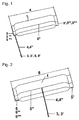
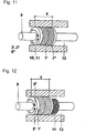
- the Fig. 1 shows the device consisting of a cut flat hose bag [1, 6] with a compressed air valve [3, 3 '] which is connected to a metal, plastic-coated valve extension [4,4 "], which is located on one of the transverse sides of the flat hose cushion and at
- the design as a flat hose cushion is achieved by producing pressure-tight closures at both ends (lateral sides) [5, 5 ', 5 "', 5""] and in longitudinal direction [5"].
- the flat hose cushion [1] is inserted in a circular manner between the wall opening and jacket pipe, cable duct and media pipe or multiple media pipe, multiple cable.
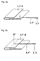
- the Fig. 2 shows one of the Fig. 1 similar device for longitudinal use in rectangular cable ducts or for sealing gaps in partition walls, wherein the compressed air valve [3, 3 '] after Fig. 6b can be attached to the longitudinal side [5 "] of the flat tube cushion.
- the Fig. 3 shows one of the Fig. 1 and 2 similar device, which has two compressed air valves [3, 3 '] with valve extension [4] and is suitable for filling the flat tubular bag with gaseous, powdered or liquid media. While the first compressed air valve is used for filling, the second compressed air valve [3, 3 '] can be used to discharge the compressed air during filling.
- Fig. 4 shows a similar device of Fig. 1, 2 and 3 which is limited in length [6] to the entire inner circumference of the wall breakthrough, casing tube, Lucaskanalohrs or the length of the gap in partitions and in the width [1 '] to be filled cavity to the media tube or the partition wall.
- Upper [2] and lower surface [2 '] of the flat tubular bag can be prefabricated partially or completely with a sealing tape [7], which may have elongated projections [7'].
- the full-surface application or stringing the Abdichtb species [7 "] on the flat hose cushion is advantageous when used in wall breakthroughs.
- Fig. 5a to 5h show perspectively various embodiments of a pressure-tight flat-tube cushion closure with valve, and in particular how the metal, plastic-coated valve extension [4] in the flat hose cushion [1, 1 ', 6] can be introduced.
- Fig. 5a shows a partial perspective view of the in Fig. 1 . 3 . 4 and 16a described end closure [1, 1 ', 6] on the transverse side of the flat tube pad manufactured from an overlapping folded composite foil. The end was shown here in the unlocked state to show the position of the special valve [4, 3, 3 '] on the pressure-tight closure.
- Fig. 5b shows a partial perspective view of the in Fig. 2 .
- the plastic-coated valve extension [4] of the special valve [3, 3 '] is inserted in the longitudinal welding [5 "] of the overlapping folded composite film of the flat tube cushion to the location of the special valve of the Fig. 2 inside the pressure-tight longitudinal welding [5 "] of the flat hose cushion [1].
- Fig. 5c shows a perspective view of the in Fig. 1 . 3 . 4 . 5a . 5d . 5g . 5h and 16a described Flachschlauchkissens [1, 1 ', 6] formed from a composite film with pressure-tight fasteners on the transverse sides [5, 5', 5 "] and the film overlap in the longitudinal direction [5"].
- the end closure [5, 5 ', 5 ", 5"'] produced by means of heat-sealing or high-frequency welding processes has a smooth design Fig. 5a with a composite film thickness of 250 to 600 .mu.m, accommodates an inserted special valve [4, 3, 3 '] Fig. 6a and with a circular application of a bending shear stress of the composite foil-plastic-metal compound of 100 - 120 N / cm withstand.
- Fig. 5d shows a perspective view of the in Fig. 1 . 3 and 4 described flat hose pad [1, 1 ', 6] with two, produced in heat-sealing or high-frequency welding process, pressure-tight fasteners [5, 5', 5 "] on the two transverse sides of the flat hose cushion and a pressure-tight welded metal, plastic-coated valve extension [4 '] which is connected in the interior of the flat hose cushion, with a perforated, flexible plastic hose extending over the entire length of the flat hose cushion [6], which serves for uniform distribution of the filling in the case of long flat hose cushions a passenger car compressed air valve [3, 3 '] for filling the flat tube pad with filling media [8, 8'] attached.
- the flat-tube cushion [1, 1 ', 6] has been shown here in the cut-open state in order to show the position of the valve extension [4, 4'] within the flat-tube cushion.
- Fig. 5e shows a perspective view of the in the FIGS. 1 . 3 . 4 . 5d and 16a for the circular application which is formed from a composite film with pressure-tight closures on the two transverse sides [5, 5 '] and from an overlap [5 "] in the longitudinal direction
- the end closure produced by means of heat-stamp welding [5, 5 '] has a honeycomb or corrugated design Fig. 5g and 5h on.
- the honeycomb or corrugated closure surface [5 ""] allows for increased flat-tube cushion inflation pressure and shear stress resistance of 120-140 N / cm.
- One or two special valves [4, 3, 3 '] can be welded into the end closure.
- Fig. 5f shows a perspective view of the in the Fig.
- the flat-tube cushion [1, 1 ', 6] which is formed from a composite film with pressure-tight closures on the transverse sides [5, 5', 5 ""] and an overlap [5 "] in the longitudinal direction
- the end closure produced by means of a hot-stamp welding process on the transverse sides [5, 5 ', 5 "] has a smooth, honeycomb-shaped or corrugated configuration and an additional metal or Kunststoffverpressung [5"'], which withstand longitudinal longitudinal application of the flat hose cushion additional internal overpressure shear forces In the overlap [ 5 "] of the composite foil, one or two special valves [4, 3, 3 '] can be welded.
- Fig. 5g shows a cross section of the Fig. 5c . 5e and 5f a pressure-tight end closure [5, 5 '] with a metal plastic-coated special valve [4, 4 ", 3, 3'] after Fig. 6a or 6b and a honeycomb-shaped or wavy configuration of the closure upper or lower surface [5 ""] under shear stress [18] with a flat-tube cushion filling pressure of ⁇ 2 bar.
- the end closure is shown here in the extended state as in longitudinal application as a lifting and sealing element for spaces in partitions.
- Fig. 5h shows a cross section of the Fig. 5g a pressure-tight end closure [5, 5 '] with plastic-metal compound at a flat hose pad filling pressure of ⁇ 4 bar.
- the pressure-tight end closure on the transverse side [5,5 '] has a plastic-coated, metal special valve [4, 4 ", 3, 3'] and a honeycomb-shaped or corrugated configuration of the closure upper or lower surface [5""]
- End closure is here shown in the bent state as in the circular application as a sealing element in pipe runs.
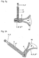
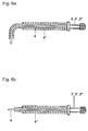
- the Fig. 6a and 6b show a perspective view of the in the Fig. 5a . 5c . 5d . 5e . 5g and 5h shown special valve in the bent state or in the Fig. 5b and 5f shown special valve in the straight state, consisting of a compressed air valve [3, 3 ', 3 "] with metallic valve extension [4], which is plastic-coated for mechanical thermic reasons of the connection between metal [4] and flat hose cushion [1] with PE, PUR or PA and as a bending protection of the metal valve extension [4 '] additionally comprises a heat-shrinkable tube [4 "].
- FIGS. 7 to 14 show different embodiments of in Fig. 1 . 3 . 4 and 16a described apparatus for the circular arrangement of the device as a sealing element in wall openings [10], smooth or corrugated liners (sleeve) [1o] or cable channels [11].
- Fig. 7 shows a cross section of in Fig. 1 . 4 .
- the device consists of one or two prefabricated flat hose cushions [1, 1 ', 6] with a metal compressed air valve [3, 3', 8, 8 "] which is provided with a plastic-coated valve extension [4, 4"].
- the Fig. 8 shows one of the Fig. 7 similar device, in which the flat tubular bag [1] for filling with liquid filling media [8 '] at each pressure-tight closure on the transverse sides [5, 5'] of Fig. 3 and 16b is equipped with a metal, plastic-coated valve extension [4, 4 "] and a compressed air valve [3 ']
- a valve adapter with shut-off valve can be used to drain off the liquid filling media.
- Fig. 9 is one of the Fig. 7 Similar design of the seal for multi-media pipes or multi-cable [12] shown in which each individual media tube and / or cable before filling the flat tubular bag [1, 6] outside the sealing with sealing tape [7 "'] wrapped and this winding then under the Flat hose cushion [1] is pushed with prefabricated sealing tape [7, 7 "]. After filling the flat hose cushion [1] via the compressed air valve [3, 3 ', 3 ", 4, 4"] and pressing the sealing tapes [7, 7'"], all cavities [13] are sealed under pressure gas and water tight.
- Fig. 10 shows one who Fig. 8 similar perspective view of the sealing device with brandabschottender additional function.
- sealing device is located in the center of the wall duct [10], around the media tube [9], multi-media tube [12] or the cable duct [11] wound band or hose with fire-barrier function [14].
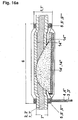
- Fig. 11 shows one of the Fig. 8 Similar sealing device consisting of a flat hose cushion [1 '] with a width of 550 mm 3 or 4 The device is used for sealing cavities [13] for wall penetrations up to 600 mm in diameter or a particularly high, flexible, friction-resistant pressure seal between wall breakthrough [10], Jacket tube / cable duct [11] and the media tube [9] .Filling of the flat tube cushion [1 '] via the compressed air valves [3'] with liquid media [8 '] achieves an increased seal.
- Fig. 12 shows one who Fig. 10 or 11 similar perspective view of the sealing device with fire-barrier additional function, in which deviates from Fig. 11 and 16b in addition to the gas-tight, watertight and flame-retardant sealing of the intermediate space [13], a fire-sealing filling hose [14] or tape is wound over the media pipe [9] and the flat hose cushion [1 '], if necessary, after Fig. 16b with fire-barrier filling [14 '. 14 "] is filled.
- the Fig. 13 shows a cross section of in Fig. 1, 2 . 3, 4 . 5d . 7 . 9 and 16a shown fully circular arranged device for sealing in the jacket tube / conduit [11] or wall breakthrough [10] laid cable or multiple and / or conduit ducts [12].
- the device is as in Fig.
- the 0.5 to 2.5 bar gas- or watertight sealing of the jacket or cable duct pipe is by increasing the internal pressure by introducing air or a liquid through the compressed air valve [3] and pressing the sealing tape [7, 2] and the flexible sealing stars [15] achieved in the gusset.
- By subsequent pressure reduction is the pressure-voltage-deformation ratio of the flat tube cushion [1] in the elastic range.
- Fig. 14 shows a cross section of the view of Fig. 13 in which the flat hose cushion [1 "] is placed semicircularly around a large outer diameter cable / tube assembly [12] which is located in a jacket / conduit channel [11] or a wall opening [10] pressure-tight and watertight sealing of the cable / pipe assembly [12] in the cable duct / jacket pipe [11] or wall opening [10] by inserting the pipe / cable assembly into the sealing star [15], the sealing tape [2 , 2 ', 7] and the compression achieved by the flat-tube cushion [1 "].
- FIGS. 15a to 15b show various possible embodiments of in Fig. 13 and 14 described two-part sealing stars [15] for standard multi-tubes or multi-cable with defined outer diameter, which are used in the cable duct / jacket tube [11].
- Fig. 15a shows a cross section through an unclosed two-part sealing star [15, 15 '] for four pipes or cables.
- Fig. 15b shows a cross section through an unclosed two-part sealing star [15, 15 '] for five pipes or cables
- Fig. 16a and 16b show a perspective view of the ins Fig. 1-4 .
- 5d shown Flachschlauchkissens [1,1 ', 1 "', 6] in the cut state, the factory with a fire-barrier filling and a Brandabschottenden wrapping was provided.
- Fig. 16a shows a perspective view of the in Fig. 1 . 4 . 5d . 7 . 9-13 shown apparatus for fully circular arrangement in the jacket tube, cable duct pipe or in the wall opening.
- the device is as in Fig. 1 . 4 . 5d . 7 . 9-13 from a prefabricated flat hose cushion [1, 1 ', 6] with factory-integrated fire-barrier filling made of an elastic fire-barrier base polymer tape [14'] or a granulate [14 "] and a metal compressed air valve [3, 3 '] Fig. 6a with plastic-coated valve extension [4, 4 "].
- the ends of the flat-tube bag were closed by a suitable process to form corrugated, honeycomb-shaped [5""] or smooth [5, 5 '] closures shear resistant [18] to 5 bar filling pressure.
- conduit or wall breakthrough in the middle of the device was a pre-assembled, not permanently bonded to the components sealing tape [2, 2 ', 7, 7'] and on both outer sides of a fire-barrier sealing tape [14 "'] around the flat hose cushion [1, 1', 6]
- the gas- and water-tight sealing of the jacket or cable duct pipe is achieved by increasing the filling pressure by introducing air or a liquid via the compressed air valve [3, 3 '] and compression of the sealing band [7, 2] or the flexible sealing stars in the gusset achieved by subsequent pressure reduction, the pressure-voltage-deformation ratio of the flat tube pad [1] is in the elastic range.
- Fig. 16b shows a perspective view of the in Fig. 1-4 . 5d shown device in the cut state for longitudinal application in the rectangular cable duct or in wall ducts with laid cables / media tubes.
- the device is as in Fig. 1-5 . 5d and 16a from a prefabricated flat hose cushion [1, 1 ', 6] with factory-integrated fire-barrier filling [14', 14 "] and external fire-barrier tape winding [14 '"'] and gas-tight and waterproof sealing tape winding [2, 2 ', 7, 7 '] and one or two plastic-coated metal Compressed air valves [3, 3 ', 4, 4 "] Fig.
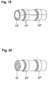
- Fig. 17 shows a perspective view of the in Fig. 2 . 3 . 4 and 16b rectangularly arranged device for sealing the cables and / or pipes laid in the cable duct [11] or between separating / partitions [9].
- the device is as in Fig. 2 . 3 . 4 and 16b described prefabricated flat hose cushion [1, 1 ', 6] with a compressed air valve [3, 3'] after Fig. 6b , which is provided with a plastic-coated valve extension [4.4 "] at the longitudinal weld [5"].
- the ends [5, 5 ', 5 "', 5""] of the flat-tube cushion were closed by means of a suitable method to internal over-pressure shear-resistant closures [5"', 5 "”].
- a prefabricated sealing tape [7, 7 ', 7 "] not permanently bonded to the components was wound around the flat hose cushion [1, 1', 6].
- a two-part sealing block [15 "] or slotted rows of single blocks [16] with anchorages to the outer sealing block [15] is used to seal the cables and / or pipes [9] laid in the cable duct or between partition walls [11] '] / Single block sides [16'] and anchors, recesses on the inner sealing block sides [15 "", 16 "] and on the outer side of the cable / pipe, blind plug [17] or the cable / pipe adapter [17 '].
- the tensile / compression-resistant and fire-resistant 0.5 bar gas or watertight sealing of the cable duct [11] is achieved by increasing the internal pressure by introducing air or a liquid via the compressed air valve [3, 3 '] and pressing the sealing tape [7 ] and the sealing block [15, 16, 17] achieved in the gussets.
- By subsequent pressure reduction is the pressure-strain-deformation ratio of the flat tube cushion [1, 1 ', 6] in the elastic region.
- Fig. 18 shows a perspective view of the in Fig. 17 described sealing device made of a two-part sealing block [15 "] with juxtaposed single blocks [16] shown in pulled-apart state to show the position of the anchors on the upper and lower sides [15"'] of the sealing block and single block.
- Fig. 19 shows a perspective view of the in Fig. 17 slotted cable / pipe adapter [17 '] with anchors on the outside [17 "] for absorbing tensile and shear forces.
- Fig. 20 shows a perspective view of the in Fig. 17 Blind stopper [17] with anchors on the outside [17 "] for use as a sealing element for uncovered sealing or single blocks.
Landscapes
- Engineering & Computer Science (AREA)
- General Engineering & Computer Science (AREA)
- Mechanical Engineering (AREA)
- Architecture (AREA)
- Civil Engineering (AREA)
- Structural Engineering (AREA)
- Rigid Pipes And Flexible Pipes (AREA)
Description
Die Erfindung betrifft eine Vorrichtung zum gas- und druckwasserdichten Verschließen von Hohlräumen zwischen Mauerdurchbrüchen und Mantel- und Medienrohren sowie von Hohlräumen zwischen Kabelkanälen, Futterrohr (Hülse) und Mehrfach-Medienrohren oder Mehrfach-Kabeln und zur Abdichtung von Zwischenräumen bei Stellwänden, die zusätzlich zur abdichtenden Funktion eine brandabschottende Funktion einnehmen kann, gemäß dem Oberbegriff des Anspruchs 1 (
Aus Patentanmeldung
Eine der bekanntesten Abdichtungen zwischen Rohr und Mehrfachmedienrohr, sowie bei Mauerwerken zwischen Futterrohr (Hülse) zu Mehrfach-Medienrohren oder Mehrfach-Kabeln ist in der
Aus der Patentanmeldung
Eines der bekanntesten Abdichtelemente für Zwischenräume von Kabelkanal und Rohren mit Innendurchmesser von 50 bis 200 mm ist in der
Ein weiterer Nachteil ist, dass das Abdichtelement an seiner mit dem Kabelschutzrohr in Kontakt stehenden Außenfläche und mit seiner Innenfläche mit den im Kabelschutzrohr eingelegten Kabeln verklebt und somit einen erheblichen Arbeitsaufwand beim Auswechseln des Abdichtelements, z.B. bei neuer Kabelbelegung, verursacht. Ein großer Nachteil ist, dass das Abdichtelement kein Druck- Ein-/ Auslaßventil besitzt und somit weder zu einem späteren Zeitpunkt nachbefüllt werden kann, noch wieder verwendbar ist. Das Einfüllventil ist bei diesem Element in Form eines Schlauches ausgebildet, der nach der Erstbefüllung beim Herausziehen automatisch eine Sonde abdichtet. Ein zweites Einfüllventil ist nicht vorgesehen,One of the most well-known sealing elements for interstices of cable duct and pipes with internal diameter of 50 to 200 mm is in the
A further disadvantage is that the sealing element adheres to its outer surface which is in contact with the cable protection tube and with its inner surface to the cables inserted in the cable protection tube and thus causes a considerable amount of work when replacing the sealing element, eg with new cable assignment. A major disadvantage is that the sealing element has no pressure inlet / outlet valve and thus can not be refilled at a later time, nor is it reusable. The filling valve is formed in this element in the form of a tube that automatically seals a probe after the initial filling when pulling out. A second filling valve is not provided,
Ein weiterer Nachteil bei diesem System mit Brechkapsel ist, dass bei einem Abdicht- elementbauteil die Druckdifferenz zwischen einem oder mehreren abzudichtenden Kabeln entweder zu niedrig oder zu hoch ist und demzufolge entweder zur Undichtheit des Abdichtsystems oder zur Einbeulung und Schädigung der abzudichtenden Kabel oder Rohre führt.
A further disadvantage of this crushing capsule system is that, in a sealing member, the pressure differential between one or more cables to be sealed is either too low or too high, resulting in either leakage of the sealing system or buckling and damage of the cables or pipes to be sealed.
Die Aufgabe der Erfindung besteht darin, eine Abdichtvorrichtung gemäß der im Oberbegriff des Anspruchs 1 genannten Art zu schaffen, die zum Abdichten der Hohlräume zwischen Mauerdurchbrüchen und Mantel- und Medienrohren, zwischen Kabelkanälen/ Futterrohren (Hülse) und Kabeln/ Rohren, sowie von Zwischenräumen von Stellwänden, bei Horizontalbohrungen (Unterquerungen) und bei Fernwärme-, Gas-, (Ab-)Wasser- oder Kabelkanälen gegen Gas und drückende Wasser geeignet ist und die je nach Anforderung zusätzlich mit einer brandabschottenden Funktion ausgerüstet sein kann.The object of the invention is to provide a sealing device according to the type mentioned in the preamble of
Die Abdichtvorrichtung soll universell für ein breites Anwendungsspektrum geeignet sein und mittels hoher Flächenanpressdruckbreite nur einen geringen wirksamen Flächenanpressdruck aufbringen, um mechanische oder übertragungstechnische Eigenschaftsänderungen von Medienrohren oder Kabeln zu vermeiden. Desweiteren sollen mit dieser Abdichtvorrichtung Mauerdurchbrüche, Mantelrohre und Kanäle im Durchmesser bis etwa 600 mm und einer Länge von bis zu 10 m wirtschaftlich, ohne fremde Hilfe, schnell und zuverlässig abgedichtet werden können.
Die Abdichtung soll eine erhöhte Brauchbarkeitsdauer besitzen, mehrfach wieder verwendbar sein und auch unter Umweltbedingungen z.B. bei normalen Relativbewegungen von Rohren und Kabeln, Lagerung in Chemikaliengemischen pH2 bis pH12 und bei Temperaturwechselbeanspruchung noch zuverlässig abdichten.
Darüber hinaus soll die vorliegende Erfindung auch zum gas- und wasserdichten Verschließen von glatten oder gewellten Rund- oder Rechteck-Kabelkanälen, sowie von Zwischenräumen bei Stellwänden eingesetzt werden können und je nach Anforderung zusätzlich eine brandabschottende Funktion (z.B. bei der Gebäudeverkabelung) einnehmen können.The sealing device should be universally suitable for a wide range of applications and apply by means of high surface contact pressure only a small effective surface pressure to avoid mechanical or transfer technical property changes of media pipes or cables. Furthermore, with this sealing wall openings, casings and channels in diameter up to about 600 mm and a length of up to 10 m economically, without external help, can be sealed quickly and reliably.
The seal should have an increased useful life, be reused several times and also under environmental conditions, for example, during normal relative movements of pipes and cables, storage in chemical mixtures pH2 to pH12 and with thermal cycling still reliably seal.
In addition, the present invention should also be used for gas- and watertight sealing of smooth or wavy round or rectangular cable ducts, as well as gaps in partitions and, depending on the requirements in addition fire retardant function (eg in the building cabling) can take.
Diese Aufgaben werden mit den Merkmalen des Anspruchs 1 gelöst:These objects are achieved with the features of claim 1:
Bei den aus den Patentanmeldungen
Bei Verwendung als Abdichtvorrichtung zum gas- und druckwasserdichten Verschließen von Zwischenräumen enthält das als Flachschlauchkissen ausgebildete Abdichtelement je nach Anwendungsbereich auf der Außenseite ein Abdichtband, das aus einer Chemiefaser-Trägereinlage mit einer dem jeweiligen Anwendungsbereich optimierten Beschichtung versehen ist, besteht und welches die Außenseite des Flachschlauchkissens ganz oder teilweise bedeckt, um dieses vor Beschädigungen durch Unebenheiten oder Steine im Mauerwerk oder im Rohr zu schützen.
Für die Abdichtbänder wird je nach Anwendungsbereich eine Abdichtmasse aus Petrolat-Vaseline-Gemisch oder Petrolat-Bitumen-Gemisch gewählt, die beidseitig auf die Chemifaser-Trägereinlage des Abdichtbandes aufgebracht ist und die entweder eine geringe oder eine hohe Adhäsionskraft zum Flachschlauchkissen aufweist.
Auf der Innenseite des Flachschlauchkissens, die zum innenliegenden Kabel-/ Medienrohr zeigt, enthält das Flachschlauchkissen wiederum ein Abdichtband, welches das Flachschlauchkissen teilweise bedeckt, um eine völlige Abdichtung der Hohlräume zwischen Mauerdurchbruch, Mantel-, Medienrohr und Kabel etc. zu erzielen.In the case of the patent applications
When used as a sealing device for gas and pressurized water-tight sealing of gaps formed as a flat hose cushion sealing element depending on the application on the outside of a sealing tape, which is provided with a chemical application base liner optimized for the respective application area, and which is the outside of the flat hose cushion completely or partially covered to protect it from damage from bumps or stones in the masonry or in the pipe.
Depending on the field of application, a sealing compound of petrolatum-vaseline mixture or petrolatum-bitumen mixture is selected for the sealing tapes, which is applied on both sides to the chemical fiber carrier insert of the sealing tape and which has either a low or a high adhesive force to the flat tube cushion.
On the inside of the flat tube cushion, which points to the inner cable / media tube, the flat tube cushion in turn contains a sealing tape, which partially covered the flat hose cushion to achieve a complete seal of the cavities between the wall opening, jacket, media tube and cable, etc.
Bei mehrfach belegten Mauerdurchführungen, Mantelrohren oder Kabelkanälen ist jedes einzelne abzudichtende Medienrohr oder Kabel mit einem dauerhaft verklebenden Dichtband zu umschließen oder bei weniger als drei Kabeln/ Rohren mit dem Flachschlauchkissen zu umlegen.For multi-use wall ducts, jacket pipes or cable ducts, each individual media pipe or cable to be sealed must be enclosed with a permanent adhesive sealing tape or, if there are fewer than three cables / pipes, enclosed with the flat hose cushion.
Beim Abdichten von Standard-Mehrfachrohren oder -kabeln zur Mauerdurchführung oder Mantelrohr können die zu umschließenden Kabel und Rohre bauseitig mit einem elastischen, geteilten Dichtstern oder Dichtblock ausgefüllt werden, der je nach Anwendungsfall nicht dauerhaft mit den Kabeln oder Rohren verklebt.When sealing standard multiple pipes or cables to the wall duct or jacket pipe, the cables and pipes to be enclosed can be filled on site with an elastic, split sealing star or sealing block, which does not permanently bond with the cables or pipes, depending on the application.
Für eine gleichmäßige Druckverteilung wird das Flachschlauchkissen in zwei Lagen kreisförmig an der Innenseite des Mantelrohres oder der Mauerdurchführung eingelegt. Die Befüllung des Flachschlauchkissens erfolgt über ein oder zwei metallene Ventile, welche mit kunststoffbeschichteten metallenen Verlängerungen verbunden sind, die in das Flachschlauchkissen eingeschweißt sind. Bei Anwendungen wo das Flachschlauchkissen in zwei Lagen eingebracht wird, ist an der metallenen, kunststoffbeschichteten Ventilverlängerung im Inneren des Flachschlauchkissens eine perforierte Kunststoffleitung angebracht, die eine optimale Druckverteilung gewährleistet.For a uniform pressure distribution, the flat hose cushion is inserted in two layers in a circle on the inside of the jacket pipe or the wall duct. The filling of the flat tube pad via one or two metal valves, which are connected to plastic-coated metal extensions, which are welded into the flat hose cushion. In applications where the flat hose cushion is placed in two layers, a perforated plastic pipe is attached to the metal, plastic-coated valve extension inside the flat hose cushion to ensure optimum pressure distribution.
Die Ventilkonstruktion besteht aus einem metallenen Druckluftventil mit einer Kunststoff- und Wärmeschrumpfschlauch beschichteten metallenen Ventilverlängerung, die an einer oder an beiden Querseiten thermisch am Flachschlauchkissen eingeschweißt ist. Diese Ventilkonstruktion ermöglicht eine hohe Biegestabilität beim Ausformen der Ventilverlängerung und besitzt eine, nach dem heutigen Stand der Technik geringere Leckrate von < 5,8 x 10⁻⁸ mbar I/sec (Helium), womit die, dem heutigen Stand der Technik entsprechende Brauchbarkeitsdauer von 20 Jahren übertroffen wird.The valve design consists of a metal compressed air valve with a plastic and heat shrink tubing coated metal valve extension, which is thermally welded on one or both sides of the flat hose cushion. This valve construction allows a high bending stability when forming the valve extension and has a, according to the state of the art lower leakage rate of <5.8 x 10 -8 mbar I / sec (helium), which corresponds to the, the current state of the art useful life of 20 years is exceeded.
Die erweiterte Brauchbarkeitsdauer der Erfindung wird dadurch gewährleistet, dass einerseits die Leckrate des Flachschlauchkissens zum Stand der Technik wesentlich verbessert wurde und andererseits der Druckverlust bedingt durch Diffusion durch das Flachschlauchkissen und dem Kriechmodul der Abdichtmaterialien durch Nachfüllen des Fülldrucks über das Ventil während der Anlagen-Wartungszyklen möglich ist.
Mit der Konstruktion der Erfindung kann einerseits erstmals der Flächenanpressdruck entsprechend dem Anforderungsprofil variabel auf einer Ringdrucklänge (Flachschlauchkissenbreite) von 40 bis ca. 300 mm und einem korrespondierenden Flächenanpressdruck von 15 und 40 N/cm2 angepasst werden, welches einem Fülldruck des Flachschlauchkissens zwischen 1,5 bar und 5 bar entspricht.The extended useful life of the invention is ensured by, on the one hand, significantly improving the leaking rate of the prior art flat tube pad and, on the other hand, allowing the pressure loss due to diffusion through the flat tube pad and the creep modulus of the sealing materials by replenishing the inflation pressure through the valve during plant maintenance cycles is.
With the construction of the invention, on the one hand, for the first time, the surface pressure corresponding to the requirement profile can be variably adjusted to a ring pressure length (flat tube cushion width) of 40 to approx. 300 mm and a corresponding surface pressure of 15 and 40 N / cm 2 , which corresponds to a filling pressure of the flat tube cushion between 1, 5 bar and 5 bar corresponds.
Ein weiterer Vorteil der Konstruktion der Erfindung ist, dass bei gewünschter Befüllung des Flachschlauchkissen mit flüssigen oder pulverisierten Medien, das Flachschlauch-kissen mit zwei Stück metallenen, kunststoffbeschichteten Ventilverlängerungen ausgestattet ist, um die Medien ohne Luftpolster einbringen zu können. Die Befüllung mit flüssigen oder pulverisierten Medien kann aus Gründen der Abdichtung gewünscht sein, z.B. bei gewünschter Gewichtsbelastung beim Abdichten von Zwischenräumen bei Stellwänden.Another advantage of the construction of the invention is that when desired filling the flat tube cushion with liquid or powdered media, the flat-tube cushion is equipped with two pieces of metal, plastic-coated valve extensions to bring the media without air cushion can. The filling with liquid or powdered media may be desired for reasons of sealing, e.g. at desired weight load when sealing gaps in partitions.
Durch die Breite des Flachschlauchkissens von 100 bis über 370 mm ist erstmals ein hoher Reibschluß zwischen Mauerdurchbruch, Mantel- / Medienrohr und Kabel möglich und ein zum Abdichten von Hohlräumen benötigter Schlauch im Durchmesser von etwa 60 bis 236 mm ist herstellbar.Due to the width of the flat hose cushion from 100 to more than 370 mm, for the first time a high frictional engagement between wall breakthrough, sheath / media pipe and cable is possible and a hose for sealing cavities required in the diameter of about 60 to 236 mm can be produced.
Beim Abdichten von rechteckigen Kabelkanälen wie sie z.B. bei Gebäudeverkabelungen eingesetzt werden oder bei Kabelkanälen, die mit Mehrfachrohren und/ oder mit mehr als einem Kabel belegt sind, wird im Bereich der Stellen, wo sich die Kabel und/ oder Kabelschutzrohre berühren, ein vorgeformter geteilter elastischer Dichtblock eingelegt.When sealing rectangular cable ducts such as those used in building cabling or cable ducts, which are covered with multiple tubes and / or with more than one cable, is in the area where the cables and / or cable protection tubes touch, a preformed split elastic Inserted sealing block.
Ein wesentlicher Vorteil der Konstruktion der Erfindung ist, dass das Flachschlauchkissen werkseitig mit einem brandabschottenden Material gefüllt sein kann, welches bei Temperaturen von etwa 200°C durch starkes Aufschäumen des Materials (bis Faktor 10 seiner ursprünglichen Dimension) den Zwischenraum vollständig abdichtet, und das aufgeplatzte Flachschlauchkissen dadurch wieder vollständig gegen Luft oder Gase abdichtet. Bei Abdichten von Rechteckkanälen oder Zwischenräumen von Stellwänden wird das Flachschlauchkissen in einer Lage längsförmig eingelegt, wobei das Flachschlauch-kissen hierbei so ausgebildet ist, dass das/die Füllventil(e) je nach Anwend- ungsbereich in der Längsschweißnaht oder an der Querseite angebracht sind. Die Querseiten sind durch zusätzliche Metall- oder Kunststoffverpressungen gegen die von Innen auf die Enden wirkenden Abscherkräfte bis 100 N/cm abgesichert.
Die Befüllung des Flachschlauchkissens erfolgt sinngemäß wie bei der Abdichtung von runden Kanälen über ein oder zwei metallene Ventile, welche mit einer, in das Flach-schlauchkissen eingeschweißten, metallenen, kunststoffbeschichteten Verlängerung verbunden sind.A significant advantage of the construction of the invention is that the flat hose cushion can be factory-filled with a fire-barrier material, which at temperatures of about 200 ° C by strong foaming of the material (up to factor 10 of its original dimension) completely seals the gap, and the burst As a result, the flat pillow again completely seals against air or gases. When sealing rectangular channels or spaces of partitions, the flat tube cushion is inserted longitudinally in a layer, wherein the flat-tube cushion is designed so that the / the filling valve (s) are mounted depending on the application area in the longitudinal weld or on the transverse side. The transverse sides are protected by additional metal or Kunststoffverpressungen against the shearing forces acting from the inside to the ends up to 100 N / cm.
The filling of the flat tube pad is done analogously as in the sealing of round channels via one or two metal valves, which are connected to a, welded in the flat-tube cushion, metal, plastic-coated extension.
Bei Verwendung als brandabschottende Abdichtung enthält das Flachschlauchkissen im Inneren und Außen um das Kissen herum elastische brandabschottende Bänder. Zusätzlich kann der Hohlraum zwischen Mauerdurchbruch und Medienrohr/ Kabelkanal oder Kabel unmittelbar vor oder nach dem Abdichtelement mit brandabschottendem Mittel aufgefüllt werden.
Beim Aufpumpen des Flachschlauchkissens mit Luft, Gas, Pulver oder einer Flüssigkeit werden die Abdichtbänder und die eingesetzten Dichtsterne oder Dichtblöcke in die Zwischenräume gepresst und das Kabel, Kabelschutzrohr, Kabelkanalrohr so verschlossen, dass eine unter Umweltbedingungen zug- und schubfeste Gas- und Wasserdruckdichtigkeit von mind. 0,5 bis 1,5 bar oder 5 bis 15 m Wassersäule erzielt wird und dennoch Relativbewegungen von Medienrohr und Kabel durch Setzen des Erdreichs, Temperaturwechsel, Bauarbeiten etc. abgefangen werden können. Die Demontage der wieder verwendbaren Vorrichtung ist je nach Anwendungsfall z.B. durch Ablassen der Füllung über das Ventil einfach möglich.When used as a fire-barrier seal, the flat-tube cushion includes elastic fire-barrier tapes inside and outside the cushion. In addition, the cavity between the wall opening and media tube / cable channel or cable can be filled immediately before or after the sealing element with brandabschottendem agent.
When inflating the flat hose cushion with air, gas, powder or a liquid, the sealing tapes and the inserted sealing stars or sealing blocks are pressed into the interstices and the cable, cable protection tube, cable channel tube sealed so that under ambient conditions tensile and shear resistant gas and water pressure tightness of min 0.5 to 1.5 bar or 5 to 15 m water column is achieved and yet relative movements of media pipe and cable can be intercepted by setting the soil, temperature changes, construction work, etc. The disassembly of the reusable device is easily possible depending on the application, for example by discharging the filling via the valve.
Zur Abdichtung von mit Kabeln oder Rohren belegten Mauerdurchführungen werden Abdichtbänder aus einer unverrottbaren Chemiefaser-Trägereinlage eingesetzt, die beidseitig mit einem unter Druck klebenden dauerplastischen Kunststoffgemisch beschichtet sind. Mindestens eine dieser Dichtbandseiten besitzt eine nicht lösbare, hochflexible Deckfolie um eine dauerhafte Verklebung ohne Druckbeaufschlagung zwischen den Dichtbändern zu garantieren. Die Dichtbänder mit Chemiefaser-Trägereinlage garantieren eine Formbeständigkeit (Dickenänderung von 13%) bei einer Druckbelastung von 130 N/cm2. Dadurch werden Unebenheiten, Rückstände im Mauerwerk in der Rohranlage, Wellen-Tiefen-/ Höhenunterschiede bei Wellrohren, Erdreichablagerungen, Senkungen im Betrieb oder bei der Montage etc. ausgeglichen und Beschädigungen (Undichtheit) des Flachschlauchkissen unter Innenüberdruck bis 5,0 ± 0,2 bar vermieden.
Je nach Anwendungsbereich bestehen die v.g. einseitig klebenden dauerplastischen Kunststoffgemische z.B. aus einem tropf- und auspressfreien Petrolatum-Vaseline-gemisch, welches mit Quarzsand, Gesteinsmehl etc. modifiziert ist oder für Temperaturbereiche -40°C bis +90°C mit einem Zusatz von Bitumen und Prozessöl, mit Gelmassen oder flammwidrig-halogenfreiem PUR-Weichschaum modifiziert sind.
Die Erfindung wird an Hand von Ausführungsbeispielen näher erläutert.
Es zeigen:
- Fig. 1
- eine perspektivische Ansicht eines Flachschlauchkissens gemäß der Erfindung mit einem PKW-Ventil mit metallener, kunststoffbeschichteter Ventilverlängerung an der Querseite
- Fig. 2
- eine perspektivische Ansicht einer der
Fig. 1 ähnlichen Vorrichtung, die zur längsförmigen Verwendung bei Rechteckkanälen oder zum Abdichten von Zwischenräumen bei Stellwänden ein Druckluftventil an der Längsseite enthält. - Fig. 3
- eine perspektivische Ansicht einer der
Fig. 1 ähnlichen Vorrichtung die zur Befüllung mit flüssigen oder pulverisierten Medien an beiden VerschlußQuerseiten mit einem PKW-Druckluftventil versehen ist, die zumgleichzeitigen Befüllen und Entlüften des Flachschlauchkissens dienen. - Fig. 4
- eine perspektivische Ansicht einer der
Fig. 1, 2 oder 3 ähnlichen Vorrichtung, die in der Länge auf den inneren Umfang des Mauerdurchbruchs, Kabelkanals oder des Zwischenraums bei Stellwänden und in der Breite auf den auszufüllenden Hohlraum begrenzt ist, und die auf der Ober-und Unterfläche teil- oder vollflächig mit einem Abdichtband versehen ist. - Fig. 5 a
- eine perspektivische Ansicht eines aufgeschnittenen Endteils des in
Fig. 1 undbis 416a gezeigten Flachschlauchkissens, hergestellt aus einem gefalteten Band einer Verbundfolie und einer kunststoffbeschichteten, metallenen Ventilverlängerung, die an der Querseite des Flachschlauchkissenverschlusses eingebracht ist. - Fig. 5 b
- eine perspektivische Ansicht eines aufgeschnittenen Endteils des in
Fig. 5a und16b gezeigten Flachschlauchkissens, hergestellt aus einem gefalteten Band einer Verbundfolie und einer kunststoffbeschichteten, metallenen Ventilverlängerung, die an der Längsseite des Flachschlauch-kissens eingebracht ist. - Fig. 5 c
- eine perspektivische Ansicht des Endteils des in
Fig. 1, 2 ,3, 4 ,5a und 5b beschriebenen kunststoffbeschichteten Ventil-Endverschlusses, der mittels Heißsiegel-/ Hochfrequenzschweißverfahren hergestellt wurde und eine glatte Ober- / Unterseite aufweist. - Fig. 5 d
- eine perspektivische Ansicht des in
Fig. 1, 2 ,3 und 4 beschriebenen Flachschlauchkissens im aufgeschnittenen Zustand, mit einer kunststoffbeschichteten, metallenen Ventilverlängerung, die an der Querseite des Flachschlauchkissenverschlusses eingebracht ist und welche im Inneren des Flachschlauchkissens mit einem, über die gesamte Flachschlauchkissenlänge reichenden, perforierten Kunststoffschlauch versehen ist. - Fig. 5e
- eine perspektivische Ansicht des in
den Figuren 1, 2 ,3, 4 ,5a und5c gezeigten Endenverschlusses, der mittels eines Heizstempel-Schweißverfahrens hergestellt wurde und für kreisförmige Anwendungen des Flachschlauchkissens mit erhöhten Anforderungen an den Kissen-Fülldruck (Scherspannung) eine waabenförmige oder gewellte Verschluß-Ober- und -unterseite aufweist. - Fig. 5f
- eine perspektivische Ansicht des in
den Figuren 1, 2 ,3 ,5b ,5c, 5d und5e gezeigten druckdichten Verschlusses, der für längsförmige Anwendungen mit erhöhten Anforderungen an den Kissen-Fülldruck zusätzliche Metall-oder Kunststoffverpressungen aufweist - Fig. 5g
- einen Querschnitt eines druckdichten Flachschlauchkissen-Enden- verschlusses mit Ventil der
Fig. 5a ,5c und5e mit waabenförmiger oder gewellter Ausgestaltung der Verschluß- Ober- bzw. Unterseite unter Scherspannung an der Ventilverlängerung bei einem Flachschlauchkissen-Fülldruck von 3 bar - Fig. 5h
- einen Querschnitt eines druckdichten Flachschlauchkissen- Endenverschlusses der
Fig. 5g mit waabenförmiger oder gewellter Ausgestaltung der Verschluß- Ober- bzw. Unterseite unter Biege-Scherspannung an der Ventilverlängerung bei einem Flachschlauchkissen-Fülldruck von 3 bar - Fig. 6a und 6b
- eine perspektivische Ansicht des in
den Figuren 1 gezeigten, im Flachschlauchkissen eingelegten Sonderventilsbis 5 - Fig. 7
bis 14 - zeigen verschiedene Ausgestaltungen der in
Fig. 1 ,3 und 4 beschriebenen Adichtvorrichtung - Fig. 7
- zeigt die perspektivische Ansicht der in
Fig. 1 ,3 ,4 und16a beschriebenen Abdichtvorrichtung zur kreisförmigen Anordnung, mit einem Ventil zur Befüllung des Flachschlauchkissens zum gas-, druckwasserdichten und ggfs. brandabschottenden Verschließen von Hohlräumen zwischen Mauerdurchbruch und Kabel- und/oder Medienrohr, glattem oder gewelltem Futterrohr (Hülse) und glattem oder gewelltem Kabel- und/ oder Medienrohr. - Fig. 8
- zeigt die perspektivische Ansicht der
Fig. 7 mit zwei Ventilen zur Befüllung des Flachschlauchkissens mit pulverisierten oder flüssigen Füllmedien. - Fig. 9
- zeigt die perspektivische Ansicht der
Fig. 7 und 8 bei dem jedes Kabel und/oder Medienrohr mit einem Abdichtband oder einem brandabschottenden Band umwickelt wurde - Fig. 10
- zeigt die perspektivische Ansicht der
Fig. 7, 8 und9 bei dem zusätzlich ein Schlauch mit brandabschottender Abdichtung eingebracht ist. - Fig. 11
- zeigt die perspektivische Ansicht der
Fig. 1, 2 ,3, 4 und16a in der Ausgestaltung, dass das Flachschlauchkissen auf der Außenseite in der Breite vollflächig mit Abdichtband bedeckt ist, um das Flachschlauchkissen vor Beschädigungen durch Steine oder Unebenheiten etc. im Mauerwerk, Rohr etc. zu schützen. - Fig. 12
- zeigt die perspektivische Ansicht der
Fig. 10 und 11 mit der Ausgestaltung, dass zusätzlich zum Flachschlauchkissen eine brandabschottendes Medium eingebracht ist. - Fig. 13
- einen Querschnitt der in
Fig. 1 ,3 ,4 ,5d und16a gezeigten Vorrichtung, die im Kabelkanalrohr zum Abdichten von Standard-Mehrfachrohren und/oder -Kabeln kreisförmig in einer Lage um einen Dichtstern zur Aufnahme der Standard-Mehrfachrohre und/oder -Kabel angeordnet ist. - Fig. 14
- einen Querschnitt der in
Fig.. 1 ,3 ,4 ,5d und16a gezeigten Vorrichtung, die im Kabelkanalrohr zum Abdichten von Anwendungen mit Standard-Mehrfachrohren , und/oder -Kabeln mit großem Außendurchmesser halbkreisförmig um einen Dichtstern zur Aufnahme der Standard-Mehrfachrohre und/oder -Kabel angeordnet ist. - Fig. 15a
- einen Querschnitt der in
Fig. 13 und14 gezeigten zweigeteilten Dichtsterne zum Abdichten von Zwischenräumen bei Vierfach-Standard-Mehrfachrohren und/oder Kabeln. - Fig. 15b
- einen Querschnitt eines zweigeteilten Dichtsterns in ungeschlossener Ausführung zum Abdichten von Zwischenräumen bei Fünffach-Standard-Mehrfachrohren und/oder Kabeln.
- Fig. 16a
- eine perspektivische Ansicht der
Fig. 1 ,3 ,4 und5d zur kreisförmigen Anwendung im aufgeschnittenen Zustand, die bereits werkseitig mit einem brandabschottenden elastischen Grundpolymer gefüllt wurde - Fig. 16b
- zeigt wie
Fig. 2 ,5d und16a ein Flachschlauchkissen zur längsförmigen Anwendung in Rechteckkanälen oder bei Zwischenwänden, welches bereits werkseitig mit einem brandabschottenden Werkstoff gefüllt wurde - Fig. 17
- eine perspektivische Ansicht der in
Fig. 2 ,5d und16b gezeigten Vorrichtung die zum gas-, wasserdichten und brandabschottenden Verschließen von Hohlräumen zwischen Kabelkanäle und Dichtblöcke (Module) eingelegt ist - Fig. 18
- eine perspektivische Ansicht der in
Fig. 17 gezeigten Vorrichtung die zum gas-, wasserdichten und brandabschottenden Verschließen von Hohlräumen zwischen Kabelkanälen und zweigeteilten elastischen Dichtblöcken eingelegt ist - Fig. 19
- eine perspektivische Ansicht der in
Fig. 17 gezeigten Vorrichtung die zum gas-, wasserdichten und brandabschottenden Verschließen von Hohlräumen zwischen Kabelkanälen und elastischen Dicht- und Einzelblöcken eingelegt ist - Fig. 20
- eine perspektivische Ansicht des in
Fig. 17 beschriebenen Blindstopfens mit Verankerungen an der Außenseite zur Verwendung als Abdichtelement bei unbelegten Dicht- oder Einzelblöcken.
Depending on the field of application, the above-mentioned one-sided adhesive permanent plastic mixtures such as a drip and auspressfreien Petrolatum Vaseline mixture, which is modified with quartz sand, rock flour, etc. or for temperature ranges -40 ° C to + 90 ° C with an addition of bitumen and Process oil, with gel mass or flame retardant halogen-free flexible polyurethane foam are modified.
The invention will be explained in more detail with reference to exemplary embodiments.
Show it:
- Fig. 1
- a perspective view of a flat hose cushion according to the invention with a passenger car valve with metal, plastic-coated valve extension on the transverse side
- Fig. 2
- a perspective view of the one
Fig. 1 similar device, which includes a longitudinal air pressure valve for longitudinal use in rectangular channels or for sealing gaps in partitions. - Fig. 3
- a perspective view of the one
Fig. 1 similar device which is provided for filling with liquid or powdered media on both VerschlußQuerseiten with a passenger car compressed air valve, which serve for the simultaneous filling and venting of the flat tube cushion. - Fig. 4
- a perspective view of the one
Fig. 1, 2 or3 similar device which is limited in length to the inner circumference of the wall opening, cable channel or the gap in partitions and in the width of the cavity to be filled, and which is provided on the upper and lower surface partially or full surface with a Abdichtband. - Fig. 5 a
- a perspective view of a cut end portion of the in
Fig. 1 to 4 and16a shown flat tube pad, made of a folded strip of a composite foil and a plastic-coated, metal valve extension, which is introduced at the transverse side of the flat tube pad closure. - Fig. 5 b
- a perspective view of a cut end portion of the in
Fig. 5a and16b shown flat tube pad, made of a folded strip of a composite film and a plastic-coated, metal valve extension, which is introduced on the longitudinal side of the flat-tube cushion. - Fig. 5 c
- a perspective view of the end portion of in
Fig. 1, 2 .3, 4 .5a and 5b described plastic-coated valve end closure, which was produced by means of heat seal / high frequency welding process and has a smooth top / bottom. - Fig. 5 d
- a perspective view of the in
Fig. 1, 2 .3 and 4 described Flachschlauchkissens in the cut state, with a plastic-coated, metal valve extension, which is introduced at the transverse side of the flat tube pad closure and which is provided in the interior of the flat tube pad with a, over the entire flat tube pad length reaching, perforated plastic tube. - Fig. 5e
- a perspective view of the in the
FIGS. 1, 2 .3, 4 .5a and5c shown end closure, which has been produced by means of a hot stamp welding process and for circular applications of the flat hose cushion with increased requirements on the pad filling pressure (shear stress) has a waabenförmige or undulating closure top and bottom. - Fig. 5f
- a perspective view of the in the
FIGS. 1, 2 .3 .5b .5c, 5d and5e shown pressure-tight closure, which has additional metal or plastic encapsulation for longitudinal applications with increased requirements for the cushion filling pressure - Fig. 5g
- a cross-section of a pressure-tight flat-tube cushion end closure with valve
Fig. 5a .5c and5e with waabenförmiger or corrugated configuration of the closure top or bottom under shear stress on the valve extension at a flat hose pad filling pressure of 3 bar - Fig. 5h
- a cross-section of a pressure-tight Flachschlauchkissen- end closure of
Fig. 5g with a honeycomb or corrugated configuration of the closure top or bottom under bending shear stress on the valve extension at a flat hose pad filling pressure of 3 bar - Fig. 6a and 6b
- a perspective view of the in the
FIGS. 1 to 5 shown, inserted in the flat hose cushion special valve - Fig. 7 to 14
- show different embodiments of in
Fig. 1 .3 and 4 described Adichtvorrichtung - Fig. 7
- shows the perspective view of in
Fig. 1 .3 .4 and16a sealing device for circular arrangement, with a valve for filling the flat tubular bag for gas-, pressure-water tight and possibly. Brandabschottenden closing of cavities between the wall opening and cable and / or media tube, smooth or wavy casing (sleeve) and smooth or wavy cable and / or or media tube. - Fig. 8
- shows the perspective view of
Fig. 7 with two valves for filling the flat bag with powdered or liquid filling media. - Fig. 9
- shows the perspective view of
FIGS. 7 and 8 in which each cable and / or media tube was wrapped with a sealing tape or a fire-barrier tape - Fig. 10
- shows the perspective view of
Fig. 7, 8 and9 in addition, a hose is introduced with fire-barrier sealing. - Fig. 11
- shows the perspective view of
Fig. 1, 2 .3, 4 and16a in the embodiment that the flat tube cushion is covered on the outside in width over its entire surface with sealing tape to the flat tube cushion to protect against damage by stones or bumps etc. in the masonry, pipe etc. - Fig. 12
- shows the perspective view of
Fig. 10 and11 with the configuration that, in addition to the flat tube cushion a Brandabschottendes medium is introduced. - Fig. 13
- a cross section of in
Fig. 1 .3 .4 .5d and16a shown device which is arranged in the cable duct tube for sealing standard multi-tubes and / or cables circular in a position around a sealing star for receiving the standard multi-tubes and / or cables. - Fig. 14
- a cross section of in
Fig. 1 .3 .4 .5d and16a shown device which is arranged in the cable duct tube for sealing applications with standard multi-tubes, and / or cables with a large outer diameter semicircular around a sealing star for receiving the standard multi-tubes and / or cables. - Fig. 15a
- a cross section of in
Fig. 13 and14 shown two-part sealing stars for sealing gaps in quadruple standard multi-tubes and / or cables. - Fig. 15b
- a cross section of a two-part sealing star in open-circuit design for sealing gaps in five-fold standard multi-tubes and / or cables.
- Fig. 16a
- a perspective view of
Fig. 1 .3 .4 and5d for circular application in the cut state, which was already factory-filled with a fire-barrier elastic base polymer - Fig. 16b
- shows how
Fig. 2 .5d and16a a flat tube cushion for longitudinal application in rectangular channels or in partitions, which has already been factory-filled with a fire-barrier material - Fig. 17
- a perspective view of in
Fig. 2 .5d and16b The device shown for gas-, waterproof and flameproof closing of Cavities between cable channels and sealing blocks (modules) is inserted - Fig. 18
- a perspective view of in
Fig. 17 shown device for gas-tight, watertight and flame-retardant sealing of cavities between cable channels and two-part elastic sealing blocks is inserted - Fig. 19
- a perspective view of in
Fig. 17 shown device for gas-tight, watertight and flame-retardant sealing of cavities between cable channels and elastic sealing and single blocks is inserted - Fig. 20
- a perspective view of the in
Fig. 17 Blind stopper described with anchors on the outside for use as a sealing element in uncovered sealing or individual blocks.
Die
Je nach Anwendungsbereich wird das Flachschlauchkissen [1] kreisförmig zwischen Mauerdurchbruch und Mantelrohr, Kabelkanal und Medienrohr oder Mehrfach- Medien-rohr, Mehrfach-Kabel eingelegt.
Durch Befüllen der Vorrichtung [1] über das Druckluftventil [3] nach
Depending on the area of application, the flat hose cushion [1] is inserted in a circular manner between the wall opening and jacket pipe, cable duct and media pipe or multiple media pipe, multiple cable.
By filling the device [1] with the compressed air valve [3]
Die
Die
Die
Die
Die Vorrichtung besteht aus einem oder zwei vorkonfektionierten Flachschlauchkissen
[1, 1', 6] mit einem metallenen Druckluftventil [3, 3', 8, 8"] das mit einer kunststoffbeschichteten Ventilverlängerung [4, 4"] versehen ist. Zum gas- und wasserdichten Verschließen des Hohlraums [13] wurde ein vorkonfektioniertes, nicht dauerhaft mit den Bauteilen verklebendes Dichtband [7] um die Ober- [2] und Unterseite [2'] des Flachschlauchkissens [1] gewickelt.
Durch Befüllen der Vorrichtung über das Druckluftventil [3, 3', 3"] mit gasförmigen Medien [8] oder flexibel aushärtenden und/ oder auflösenden Füllmedien [8"] werden die Zwischenräume [13] ausgefüllt. Nach Ablassen des Drucks aus dem Flachschlauchkissen [1] ist eine einfache Demontage möglich und das Flachschlauchkissen [1] kann wieder verwendet werden.The
The device consists of one or two prefabricated flat hose cushions
[1, 1 ', 6] with a metal compressed air valve [3, 3', 8, 8 "] which is provided with a plastic-coated valve extension [4, 4"]. For gas and watertight Closing the cavity [13], a prefabricated, not permanently bonded to the components sealing tape [7] around the top [2] and bottom [2 '] of the flat tube bag [1] was wound.
By filling the device via the compressed air valve [3, 3 ', 3 "] with gaseous media [8] or flexible hardening and / or dissolving filling media [8"], the intermediate spaces [13] are filled. After releasing the pressure from the flat hose cushion [1], a simple disassembly is possible and the flat hose cushion [1] can be reused.
Die
In
Die
Die
Zum druckgas- und wasserdichten Verschließen mit brandabschottender Funktion eines Mantelrohrs, Kabelkanalrohrs oder Mauerdurchbruchs wurde in der Mitte der Vorrichtung ein vorkonfektioniertes, nicht dauerhaft mit den Bauteilen verklebendes Abdichtband [2, 2', 7, 7'] und an den beiden Außenseiten ein brandabschottendes Abdichtband [14"'] um das Flachschlauchkissen [1, 1', 6] gewickelt. Die gas- und wasserdruckdichte Abdichtung des Mantel- oder Kabelkanalrohres wird durch Erhöhung des Fülldrucks durch Einbringen von Luft oder einer Flüssigkeit über das Druckluftventil [3, 3'] und Verpressen des Dichtbands [7, 2] oder der flexiblen Dichtsterne in den Zwickel erzielt. Durch anschließende Druckreduzierung befindet sich das Druck-Spannungs-Verformungsverhältnis des Flachschlauchkissens [1] im elastischen Bereich.
For pressurized gas and watertight sealing with fire barrier function of a jacket tube, conduit or wall breakthrough in the middle of the device was a pre-assembled, not permanently bonded to the components sealing tape [2, 2 ', 7, 7'] and on both outer sides of a fire-barrier sealing tape [14 "'] around the flat hose cushion [1, 1', 6] The gas- and water-tight sealing of the jacket or cable duct pipe is achieved by increasing the filling pressure by introducing air or a liquid via the compressed air valve [3, 3 '] and compression of the sealing band [7, 2] or the flexible sealing stars in the gusset achieved by subsequent pressure reduction, the pressure-voltage-deformation ratio of the flat tube pad [1] is in the elastic range.
Durch anschließende mechanische Metall- oder Kunststoffverpressung [5"'] der Verschlüsse [5, 5', 5""] wird die Scherfestigkeit [18] der Verschlüsse für einen erhöhten Fülldruck bei längsförmiger Anwendung erhöht.
Subsequent mechanical metal or plastic compression [5 "] of the closures [5, 5 ', 5""] increases the shear strength [18] of the closures for increased inflation pressure during longitudinal application.
[1, 1', 6] mit einem Druckluftventil [3, 3'] nach
Je nach Anwendungsbereich wird zur Abdichtung der im Kabelkanal oder zwischen Trenn-/Zwischenwänden [11] verlegten Kabel und/oder Rohre [9] ein zweigeteilter Dichtblock [15"] oder aus geschlitzten aneinandergereihten Einzelblöcken [16] mit Verankerungen an den äußeren Dichtblock [15']/ Einzelblockseiten [16'] und Verankerungen, Aussparungen an den inneren Dichtblockseiten [15"", 16"] und der äußeren Seite vom Kabel/Rohr, Blindstopfen [17] oder vom Kabel-/ Rohradapter [17'] eingelegt. Die zug-/ stauch- und brandbeständige 0,5 bar gas- oder wasserdichte Abschottung des Kabelkanals [11] wird durch Erhöhung des Innendrucks durch Einbringung von Luft, oder einer Flüssigkeit über das Druckluftventil [3, 3'] und Verpressen des Dichtbands [7] und des Dichtblocks [15, 16, 17] in den Zwickeln erzielt. Durch anschließende Druckreduzierung befindet sich das Druck-Spannungs-VerformungsVerhältnis des Flachschlauchkissens [1, 1', 6] im elastischen Bereich.
[1, 1 ', 6] with a compressed air valve [3, 3'] after
Depending on the area of application, a two-part sealing block [15 "] or slotted rows of single blocks [16] with anchorages to the outer sealing block [15] is used to seal the cables and / or pipes [9] laid in the cable duct or between partition walls [11] '] / Single block sides [16'] and anchors, recesses on the inner sealing block sides [15 "", 16 "] and on the outer side of the cable / pipe, blind plug [17] or the cable / pipe adapter [17 ']. The tensile / compression-resistant and fire-resistant 0.5 bar gas or watertight sealing of the cable duct [11] is achieved by increasing the internal pressure by introducing air or a liquid via the compressed air valve [3, 3 '] and pressing the sealing tape [7 ] and the sealing block [15, 16, 17] achieved in the gussets. By subsequent pressure reduction is the pressure-strain-deformation ratio of the flat tube cushion [1, 1 ', 6] in the elastic region.
Claims (22)
- An apparatus for gas- and pressurized-watertight closure of hollow spaces in wall lead-throughs (10), insulated pipes (11), cable conduits (11, 11', 11 ") which are occupied by pipes carrying various media, such as gas, (waste) water, distance heat, etc., or conduits (9), the apparatus comprising a flat tubular pad (1) cut to a length (6) and width (1') for the intended use, which on its longitudinal side (5") and transverse sides has pressuretight closures (5, 5', 5"', 5"") and is filled via at least one plastic-coated metal valve (3, 3') with a valve extension (4, 4', 4") and is additionally sealed off outside the flat tubular pad (1) with a gas- and pressurized-watertight sealing tape,
characterized by
a two-ply circular arrangement (13) of the flat tubular pad (1), in which, inside the flat tubular pad, over the entire length of the flat tubular pad, the valve (3', 3") communicates with a perforated plastic tube (4'). - The apparatus according to claim 1,
characterized in that
the hollow spaces are occupied by smooth or corrugated media-carrying pipes. - The apparatus according to claim 1 or 2,
characterized in that
the flat tubular pad (1) is filled with gaseous (8), powdered or liquid (8') or flexibly hardening or dissolving media (8"). - The apparatus according to one of the foregoing claims,
characterized in that
the flat tubular pad (1, 1') can be produced in widths of up to 550 mm in length (6) to suit the circumference of the wall opening (10) or of the insulated pipe/cable conduit (11, 11') or to suit the interstice in the case of adjustable walls (11") and in width (1') as a function of the size of the hollow space (13) to be sealed off, in order, depending on the intended use, with a low fill pressure of 2.0-5.0 bar and a substantially reduced transverse pressure load on the media-carrying pipe (9) of from 20 to < 90 N/cm2, to attain sealing off of the hollow space without affecting the flow properties of the media as a consequence of denting of the media-carrying pipe. - The apparatus according to one of the foregoing claims,
characterized in that
the pressuretight closures (5, 5") of the flat tubular pad, in a standard version, have a smooth structure (5, 5'), and for a higher internal overpressure shear strength (18), they have a honeycomblike or corrugated structure (5""). - The apparatus according to one of the foregoing claims,
characterized in that
the valve comprises a metal compressed-air valve (3, 3', 3") with a plastic-coated metal valve extension (4, 4"), and the plastic coating comprises a material that is the same as the tubular pad, such as PE, PU, PA or a material equally well suited to the welding process, and as a result greater durability of the apparatus is attained by refilling during the maintenance cycles. - The apparatus according to one of the foregoing claims,
characterized in that
the valve (3, 3', 3") is disposed on the transverse side (5, 5') or on the longitudinal side (5"') of the flat tubular pad (1, 1', 6), depending on the field of use, and is embodied as a passenger car or motorcycle compressed-air valve (3) or as a special valve (3', 3") and is capable of being filled with gaseous filling media (8) or powdered or liquid filling media (8'). - The apparatus according to claims 1-6,
characterized in that
the flat tubular pad (1, 1', 6), in the field of use as a single element, is disposed in two plies in a circle in the circumference of the wall lead-through (10) or media-carrying pipe (11) or sewer pipe (11, 11'), and the valve (3, 3', 3") is located on one end (5, 5', 5"") of the flat tubular pad (1, 1', 6), and by means of the plastic-coated metal valve extension (4, 4"), a special valve (3, 3', 3") that is bendable in all directions is produced, which can be laid in protected fashion in the interstice in the sealing means (13). - The apparatus according to one of the foregoing claims,
characterized in that
the flat tubular pad (1, 1', 6), for a sealing means for filling with powdered or liquid media (8') or with flexibly hardening and/or dissolving filling material (8"), includes two valves (3', 3") for air-bubble-free filling of the flat tubular pad. - The apparatus according to one of claims 1-5 and 8,
characterized in that
the flat tubular pad (1, 1', 6) in the longitudinal or transverse direction additionally has an elastic (non-) permanently adhesive sealing tape with a synthetic fiber substrate inlay (7) in a winding row or in sealing tapes (7") arranged in side-by-side rows. - The apparatus according to one of claims 1-5 and 8-10,
characterized in that
in the sealing of wall lead-throughs (10), insulated pipes (11), cable conduit (11, 11', 11 "), media-carrying pipes (9) and bundles of cables (12), a sealing tape wrapping (7, 7", 7"') with or without separating film is inserted in the vicinity of the contact points of wall lead-throughs (10), flat tubular pads (1, 1'), cable conduit (11, 11', 11") or multiple insulated pipes/multiple cables (12), and a permanently plastic sealing star (15, 15'), sealing block (15", 15"', 15""), sealing module (16, 16') or sealing tape wrapping (7) is located in the nip. - The apparatus according to claim 10 or 11,
characterized in that
in the sealing tape (7) for gastight and pressurized-watertight sealing under pressure, the sealing tape wrapping (7', 7"), depending on the field of use, comprises a modified vaseline-petrolatum mixture or a petrolatum or asphalt mixture or gel compositions or a closed-cell hard PUR foam which in the temperature range from -30°C to +70°C is permanently elastic and pressure-resistant up to 100 N/cm2 and has fillers that comprise polymers, quartz sand, or powdered slate, and which has a thickness of approximately 1.0 to 3 mm and a width of from 40 to 80% of the width of the flat tubular pad (1), given a partial-surface (7) or full-surface (7") covering of the flat tubular pad. - The apparatus according to one of claims 10-12,
characterized in that
for gastight and pressurized-watertight sealing with a fireproofing function, the sealing tape (7) located in the middle and the sealing tape wrapping (7', 7") for media-carrying pipe and cables comprise a permanently elastic woven-fabric tape that is pressure-resistant up to 100 N/cm2 and comprises a rotproof synthetic fiber substrate inlay (7) and that on both sides comprises a vaseline-petrolatum mixture, modified with fillers of polymer, quartz sand or powdered slate, or a closed-cell hard PUR foam on the synthetic fiber substrate inlay (7), the inlay having a thickness of from 2.0 to approximately 3.0 mm, and in width they cover between 20 and 40% of the surface area of the flat tubular pad (1) and of the media-carrying pipes/cables, and the remaining peripheral surfaces are covered with fireproofing tapes (14'). - The apparatus according to claims 12 and 13,
characterized in that
the sealing tapes (7, 7', 7", 7"') are enveloped on one or both sides by a soft, stretchable separating film. - The apparatus according to one of claims 10-12 and 14,
characterized in that
the sealing tapes (6) comprising a rotproof synthetic fiber substrate inlay are made from a material that is stretchable in the longitudinal and transverse directions, such as cotton, hemp, PP polyester filaments, etc. - The apparatus according to one of claims 10-13,
characterized in that
the sealing tapes (6) are embodied of a strip of closed-cell hard foam, preferably PUR or silicone, with adhesive coating on one side. - The apparatus according to one of the foregoing claims,
characterized by
being occupied by multiple media-carrying pipes/multiple cables (12), and the apparatus includes a sealing tape wrapping (7"') or a sealing star/sealing block (15, 16), which is placed between the individual cables or pipes that are to be sealed off. - The apparatus according to claim 17,
characterized in that
the sealing star (15), sealing block (15", 15"', 15""), or individual sealing block module (16, 16', 16"), split in two and unclosed (15') or closed and slit, is embodied of a transversely variable, halide-free, flame-resistant material, such as PUR polyurethane hard foam. - The apparatus according to one of the foregoing claims,
characterized by
an optionally integrated fireproofing filling (14', 14") of the flat tubular pad, for additional fireproofing closure of hollow spaces. - The apparatus according to one of the foregoing claims,
characterized in that
the apparatus is additionally sealed off, outside the flat tubular pad (1), by a fireproofing tape (14, 14', 14"), for additional fireproofing closure of hollow spaces. - The apparatus according to claim 19 or 20,
characterized in that
a fireproofing medium (14) is located ahead of the flat tubular pad or in the hollow space in the wall lead-through (13) behind or between two flat tubular pads (1, 1') in a tubular tape (14) and is embodied as a fireproofing elastic tape (14') or as a fireproofing granulate (14"). - The apparatus according to claim 19, 20 or 21,
characterized in that
the fireproofing medium or media inside and outside the flat tubular pad (14'), the fireproofing sealing tape (7) located around the media-carrying pipe/cable comprises a soft elastic tape or in the tube (14') comprises a granulate with a particle size of 2 to 3 mm, and the sealing stars (15, 15'), sealing blocks (15", 15"', 15"'), the individual sealing block module (16, 16', 16"), and the blind plugs and pipe plugs (17, 17') comprise an extruded profile section of a material which is formed of a basic polymer and expandable additives.
Applications Claiming Priority (1)
| Application Number | Priority Date | Filing Date | Title |
|---|---|---|---|
| DE102006027888 | 2006-06-17 |
Publications (2)
| Publication Number | Publication Date |
|---|---|
| EP1867904A1 EP1867904A1 (en) | 2007-12-19 |
| EP1867904B1 true EP1867904B1 (en) | 2012-11-14 |
Family
ID=38335547
Family Applications (1)
| Application Number | Title | Priority Date | Filing Date |
|---|---|---|---|
| EP06017206A Not-in-force EP1867904B1 (en) | 2006-06-17 | 2006-08-18 | Sealing device for wall lead-throughs, pipes and ducts |
Country Status (1)
| Country | Link |
|---|---|
| EP (1) | EP1867904B1 (en) |
Cited By (7)
| Publication number | Priority date | Publication date | Assignee | Title |
|---|---|---|---|---|
| EP3056621A1 (en) | 2015-02-11 | 2016-08-17 | Fibre Optics CT GmbH, Consulting & Testing | Reusable protection device to prevent water infiltration |
| EP3263964A1 (en) | 2016-07-01 | 2018-01-03 | Fibre Optics CT GmbH, Consulting & Testing | Sealing against water |
| DE202017006970U1 (en) | 2017-10-19 | 2019-01-30 | Roland Wolf | Reusable seal |
| EP3474402A1 (en) | 2017-10-19 | 2019-04-24 | Roland Wolf | Multipath seal |
| EP4140708A1 (en) | 2021-08-25 | 2023-03-01 | Roland Wolf | Device and method for producing a film tube from a film strip in a moulding collar welding method |
| EP4488559A1 (en) | 2023-07-07 | 2025-01-08 | Roland Wolf | Reusable sealing element |
| DE102023117934A1 (en) | 2023-07-07 | 2025-01-09 | Roland Wolf | Reusable sealing element |
Families Citing this family (5)
| Publication number | Priority date | Publication date | Assignee | Title |
|---|---|---|---|---|
| CN108167482A (en) * | 2018-01-18 | 2018-06-15 | 深圳市万居科技股份有限公司 | A kind of fire-preventing check valve |
| US12492551B2 (en) * | 2023-04-18 | 2025-12-09 | Dupont Safety & Construction, Inc. | Foam envelope for sealing large volumes |
| US12492550B2 (en) * | 2023-04-18 | 2025-12-09 | Dupont Safety & Construction, Inc. | Foam envelope for sealing large volumes |
| US12559935B2 (en) * | 2023-04-18 | 2026-02-24 | Dupont Safety & Construction, Inc. | Foam envelope for sealing large volumes |
| US12454822B2 (en) * | 2023-04-18 | 2025-10-28 | Ddp Specialty Electronic Materials Us, Llc | Foam envelope for sealing large volumes |
Family Cites Families (9)
| Publication number | Priority date | Publication date | Assignee | Title |
|---|---|---|---|---|
| DE41005C (en) | 1887-03-12 | 1887-10-07 | W. BAUR in Brooklyn, Staat New-York, V. St. A | Innovation in filter presses |
| US3038732A (en) * | 1958-04-07 | 1962-06-12 | Texas Pipe Line Company | Inflatable seal bushing for pipeline casing |
| GB8333722D0 (en) * | 1983-12-19 | 1984-01-25 | Raychem Gmbh | Expansible seal |
| GB9201069D0 (en) * | 1992-01-17 | 1992-03-11 | Raychem Sa Nv | Environmental sealing |
| DE19736494A1 (en) | 1997-08-22 | 1999-02-25 | Hauff Technik Gmbh & Co Kg | Sealing packing for insertion into a wall opening for the purpose of passing cables through |
| DE19803958C1 (en) | 1998-02-03 | 1999-05-06 | Hauff Technik Gmbh & Co Kg | Building wall through opening for services |
| WO2001090607A2 (en) * | 2000-05-23 | 2001-11-29 | Tdm Industries, Inc. | Flexible seal forming member |
| DE10341005A1 (en) * | 2003-09-05 | 2005-03-31 | Fibre Optics Ct Gmbh | Device for sealing, lifting objects and securing goods during transport and storage comprises a flat-hose cushion with a required length and a pressure resistant closure section at each end |
| DE502005004936D1 (en) * | 2005-01-28 | 2008-09-18 | Fibre Optics Ct Gmbh | Reusable sealing, lifting and / or securing device |
-
2006
- 2006-08-18 EP EP06017206A patent/EP1867904B1/en not_active Not-in-force
Cited By (13)
| Publication number | Priority date | Publication date | Assignee | Title |
|---|---|---|---|---|
| EP3056621A1 (en) | 2015-02-11 | 2016-08-17 | Fibre Optics CT GmbH, Consulting & Testing | Reusable protection device to prevent water infiltration |
| WO2016128435A1 (en) | 2015-02-11 | 2016-08-18 | Fibre Optics Ct Gmbh Consulting & Testing | Reusable device for protecting against water conduction |
| CN107208414A (en) * | 2015-02-11 | 2017-09-26 | R·沃尔夫 | Reusable Waterproof Conductive Guards |
| EP3263964A1 (en) | 2016-07-01 | 2018-01-03 | Fibre Optics CT GmbH, Consulting & Testing | Sealing against water |
| WO2018001896A1 (en) | 2016-07-01 | 2018-01-04 | Roland Wolf | Seal against water transmission |
| DE202017006970U1 (en) | 2017-10-19 | 2019-01-30 | Roland Wolf | Reusable seal |
| EP3474402A1 (en) | 2017-10-19 | 2019-04-24 | Roland Wolf | Multipath seal |
| DE202018006655U1 (en) | 2017-10-19 | 2022-01-12 | Roland Wolf | reusable seal |
| EP4140708A1 (en) | 2021-08-25 | 2023-03-01 | Roland Wolf | Device and method for producing a film tube from a film strip in a moulding collar welding method |
| DE102021121988A1 (en) | 2021-08-25 | 2023-03-02 | Roland Wolf | Device for producing a tubular film from a strip of film using the form shoulder welding process |
| DE102021121988B4 (en) | 2021-08-25 | 2024-06-06 | Roland Wolf | Device for producing film tubes from a film strip using the form-shoulder welding process |
| EP4488559A1 (en) | 2023-07-07 | 2025-01-08 | Roland Wolf | Reusable sealing element |
| DE102023117934A1 (en) | 2023-07-07 | 2025-01-09 | Roland Wolf | Reusable sealing element |
Also Published As
| Publication number | Publication date |
|---|---|
| EP1867904A1 (en) | 2007-12-19 |
Similar Documents
| Publication | Publication Date | Title |
|---|---|---|
| DE69220786T2 (en) | ENVIRONMENTAL SEAL | |
| EP3256656B1 (en) | Reusable protection device to prevent water infiltration | |
| DE69303610T2 (en) | SEALING DEVICE AGAINST ENVIRONMENTAL INFLUENCES | |
| EP1867904B1 (en) | Sealing device for wall lead-throughs, pipes and ducts | |
| EP0952382B1 (en) | Flexible conduit | |
| DE1525658C3 (en) | Thermally insulated conduit | |
| EP1867910A1 (en) | Conduit pipe with thermal insulation | |
| DE102009061082B4 (en) | System and method for installing a pipe in a wall opening | |
| EP2427693A2 (en) | Insulating cartridge | |
| EP3474402A1 (en) | Multipath seal | |
| EP0634602A1 (en) | Thermally insulated pipe | |
| EP1909012A2 (en) | Insulation sleeve | |
| DE4105625C2 (en) | Sealing for an interspace between a cable duct and a line laid therein, which is inflatable and impermeable to gas | |
| EP2314903B1 (en) | System and method for installing a tube in a wall opening and expanded reaction resin and cuff for the same | |
| EP2113702B1 (en) | Coupling for connecting two ends of a pipe with secondary source seal | |
| DE9407409U1 (en) | Flexible thermally insulated pipe | |
| AT510139B1 (en) | DEVICE FOR SEALING AND FIXING A PIPE INSERTED IN A BOREOUR HOLE | |
| EP3478997B1 (en) | Sealing against water | |
| DE102014009318B4 (en) | System and method for installing a pipe in a wall opening and its use | |
| EP1686670B1 (en) | Reusable sealing, lifting and/or safety device | |
| DE29815912U1 (en) | Device for partitioning cables, lines or the like | |
| CH703167A2 (en) | Composite pipe for use in remote heating pipeline above ditch on road for guiding of two separated fluid stream at different temperature, has thermal insulation layer arranged between fluid flow channels and guiding elements | |
| DE202017006970U1 (en) | Reusable seal | |
| DE9404814U1 (en) | Compensator with protective layer for pipeline construction | |
| DE202007004606U1 (en) | Device for producing a branch on a laid pipeline |
Legal Events
| Date | Code | Title | Description |
|---|---|---|---|
| PUAI | Public reference made under article 153(3) epc to a published international application that has entered the european phase |
Free format text: ORIGINAL CODE: 0009012 |
|
| AK | Designated contracting states |
Kind code of ref document: A1 Designated state(s): AT BE BG CH CY CZ DE DK EE ES FI FR GB GR HU IE IS IT LI LT LU LV MC NL PL PT RO SE SI SK TR |
|
| AX | Request for extension of the european patent |
Extension state: AL BA HR MK YU |
|
| 17P | Request for examination filed |
Effective date: 20080619 |
|
| 17Q | First examination report despatched |
Effective date: 20080728 |
|
| AKX | Designation fees paid |
Designated state(s): AT BE BG CH CY CZ DE DK EE ES FI FR GB GR HU IE IS IT LI LT LU LV MC NL PL PT RO SE SI SK TR |
|
| GRAP | Despatch of communication of intention to grant a patent |
Free format text: ORIGINAL CODE: EPIDOSNIGR1 |
|
| GRAS | Grant fee paid |
Free format text: ORIGINAL CODE: EPIDOSNIGR3 |
|
| GRAA | (expected) grant |
Free format text: ORIGINAL CODE: 0009210 |
|
| AK | Designated contracting states |
Kind code of ref document: B1 Designated state(s): AT BE BG CH CY CZ DE DK EE ES FI FR GB GR HU IE IS IT LI LT LU LV MC NL PL PT RO SE SI SK TR |
|
| REG | Reference to a national code |
Ref country code: GB Ref legal event code: FG4D Free format text: NOT ENGLISH |
|
| REG | Reference to a national code |
Ref country code: CH Ref legal event code: EP Ref country code: AT Ref legal event code: REF Ref document number: 584192 Country of ref document: AT Kind code of ref document: T Effective date: 20121115 |
|
| REG | Reference to a national code |
Ref country code: IE Ref legal event code: FG4D Free format text: LANGUAGE OF EP DOCUMENT: GERMAN |
|
| REG | Reference to a national code |
Ref country code: DE Ref legal event code: R096 Ref document number: 502006012201 Country of ref document: DE Effective date: 20130110 |
|
| REG | Reference to a national code |
Ref country code: NL Ref legal event code: VDEP Effective date: 20121114 |
|
| REG | Reference to a national code |
Ref country code: LT Ref legal event code: MG4D |
|
| PG25 | Lapsed in a contracting state [announced via postgrant information from national office to epo] |
Ref country code: ES Free format text: LAPSE BECAUSE OF FAILURE TO SUBMIT A TRANSLATION OF THE DESCRIPTION OR TO PAY THE FEE WITHIN THE PRESCRIBED TIME-LIMIT Effective date: 20130225 Ref country code: SE Free format text: LAPSE BECAUSE OF FAILURE TO SUBMIT A TRANSLATION OF THE DESCRIPTION OR TO PAY THE FEE WITHIN THE PRESCRIBED TIME-LIMIT Effective date: 20121114 Ref country code: LT Free format text: LAPSE BECAUSE OF FAILURE TO SUBMIT A TRANSLATION OF THE DESCRIPTION OR TO PAY THE FEE WITHIN THE PRESCRIBED TIME-LIMIT Effective date: 20121114 Ref country code: FI Free format text: LAPSE BECAUSE OF FAILURE TO SUBMIT A TRANSLATION OF THE DESCRIPTION OR TO PAY THE FEE WITHIN THE PRESCRIBED TIME-LIMIT Effective date: 20121114 |
|
| PG25 | Lapsed in a contracting state [announced via postgrant information from national office to epo] |
Ref country code: SI Free format text: LAPSE BECAUSE OF FAILURE TO SUBMIT A TRANSLATION OF THE DESCRIPTION OR TO PAY THE FEE WITHIN THE PRESCRIBED TIME-LIMIT Effective date: 20121114 Ref country code: PT Free format text: LAPSE BECAUSE OF FAILURE TO SUBMIT A TRANSLATION OF THE DESCRIPTION OR TO PAY THE FEE WITHIN THE PRESCRIBED TIME-LIMIT Effective date: 20130314 Ref country code: PL Free format text: LAPSE BECAUSE OF FAILURE TO SUBMIT A TRANSLATION OF THE DESCRIPTION OR TO PAY THE FEE WITHIN THE PRESCRIBED TIME-LIMIT Effective date: 20121114 Ref country code: LV Free format text: LAPSE BECAUSE OF FAILURE TO SUBMIT A TRANSLATION OF THE DESCRIPTION OR TO PAY THE FEE WITHIN THE PRESCRIBED TIME-LIMIT Effective date: 20121114 Ref country code: GR Free format text: LAPSE BECAUSE OF FAILURE TO SUBMIT A TRANSLATION OF THE DESCRIPTION OR TO PAY THE FEE WITHIN THE PRESCRIBED TIME-LIMIT Effective date: 20130215 |
|
| PG25 | Lapsed in a contracting state [announced via postgrant information from national office to epo] |
Ref country code: BG Free format text: LAPSE BECAUSE OF FAILURE TO SUBMIT A TRANSLATION OF THE DESCRIPTION OR TO PAY THE FEE WITHIN THE PRESCRIBED TIME-LIMIT Effective date: 20130214 Ref country code: SK Free format text: LAPSE BECAUSE OF FAILURE TO SUBMIT A TRANSLATION OF THE DESCRIPTION OR TO PAY THE FEE WITHIN THE PRESCRIBED TIME-LIMIT Effective date: 20121114 Ref country code: DK Free format text: LAPSE BECAUSE OF FAILURE TO SUBMIT A TRANSLATION OF THE DESCRIPTION OR TO PAY THE FEE WITHIN THE PRESCRIBED TIME-LIMIT Effective date: 20121114 Ref country code: CZ Free format text: LAPSE BECAUSE OF FAILURE TO SUBMIT A TRANSLATION OF THE DESCRIPTION OR TO PAY THE FEE WITHIN THE PRESCRIBED TIME-LIMIT Effective date: 20121114 Ref country code: EE Free format text: LAPSE BECAUSE OF FAILURE TO SUBMIT A TRANSLATION OF THE DESCRIPTION OR TO PAY THE FEE WITHIN THE PRESCRIBED TIME-LIMIT Effective date: 20121114 |
|
| PG25 | Lapsed in a contracting state [announced via postgrant information from national office to epo] |
Ref country code: IT Free format text: LAPSE BECAUSE OF FAILURE TO SUBMIT A TRANSLATION OF THE DESCRIPTION OR TO PAY THE FEE WITHIN THE PRESCRIBED TIME-LIMIT Effective date: 20121114 Ref country code: RO Free format text: LAPSE BECAUSE OF FAILURE TO SUBMIT A TRANSLATION OF THE DESCRIPTION OR TO PAY THE FEE WITHIN THE PRESCRIBED TIME-LIMIT Effective date: 20121114 Ref country code: NL Free format text: LAPSE BECAUSE OF FAILURE TO SUBMIT A TRANSLATION OF THE DESCRIPTION OR TO PAY THE FEE WITHIN THE PRESCRIBED TIME-LIMIT Effective date: 20121114 |
|
| PLBE | No opposition filed within time limit |
Free format text: ORIGINAL CODE: 0009261 |
|
| STAA | Information on the status of an ep patent application or granted ep patent |
Free format text: STATUS: NO OPPOSITION FILED WITHIN TIME LIMIT |
|
| 26N | No opposition filed |
Effective date: 20130815 |
|
| PG25 | Lapsed in a contracting state [announced via postgrant information from national office to epo] |
Ref country code: CY Free format text: LAPSE BECAUSE OF FAILURE TO SUBMIT A TRANSLATION OF THE DESCRIPTION OR TO PAY THE FEE WITHIN THE PRESCRIBED TIME-LIMIT Effective date: 20121114 |
|
| REG | Reference to a national code |
Ref country code: DE Ref legal event code: R097 Ref document number: 502006012201 Country of ref document: DE Effective date: 20130815 |
|
| BERE | Be: lapsed |
Owner name: FIBRE OPTICS CT GMBH, CONSULTING & TESTING Effective date: 20130831 |
|
| REG | Reference to a national code |
Ref country code: CH Ref legal event code: PL |
|
| PG25 | Lapsed in a contracting state [announced via postgrant information from national office to epo] |
Ref country code: MC Free format text: LAPSE BECAUSE OF FAILURE TO SUBMIT A TRANSLATION OF THE DESCRIPTION OR TO PAY THE FEE WITHIN THE PRESCRIBED TIME-LIMIT Effective date: 20121114 Ref country code: CH Free format text: LAPSE BECAUSE OF NON-PAYMENT OF DUE FEES Effective date: 20130831 Ref country code: LI Free format text: LAPSE BECAUSE OF NON-PAYMENT OF DUE FEES Effective date: 20130831 |
|
| REG | Reference to a national code |
Ref country code: IE Ref legal event code: MM4A |
|
| PG25 | Lapsed in a contracting state [announced via postgrant information from national office to epo] |
Ref country code: BE Free format text: LAPSE BECAUSE OF NON-PAYMENT OF DUE FEES Effective date: 20130831 |
|
| PG25 | Lapsed in a contracting state [announced via postgrant information from national office to epo] |
Ref country code: IE Free format text: LAPSE BECAUSE OF NON-PAYMENT OF DUE FEES Effective date: 20130818 |
|
| REG | Reference to a national code |
Ref country code: AT Ref legal event code: MM01 Ref document number: 584192 Country of ref document: AT Kind code of ref document: T Effective date: 20130818 |
|
| PG25 | Lapsed in a contracting state [announced via postgrant information from national office to epo] |
Ref country code: AT Free format text: LAPSE BECAUSE OF NON-PAYMENT OF DUE FEES Effective date: 20130818 |
|
| PG25 | Lapsed in a contracting state [announced via postgrant information from national office to epo] |
Ref country code: TR Free format text: LAPSE BECAUSE OF FAILURE TO SUBMIT A TRANSLATION OF THE DESCRIPTION OR TO PAY THE FEE WITHIN THE PRESCRIBED TIME-LIMIT Effective date: 20121114 |
|
| PG25 | Lapsed in a contracting state [announced via postgrant information from national office to epo] |
Ref country code: LU Free format text: LAPSE BECAUSE OF NON-PAYMENT OF DUE FEES Effective date: 20130818 Ref country code: HU Free format text: LAPSE BECAUSE OF FAILURE TO SUBMIT A TRANSLATION OF THE DESCRIPTION OR TO PAY THE FEE WITHIN THE PRESCRIBED TIME-LIMIT; INVALID AB INITIO Effective date: 20060818 |
|
| REG | Reference to a national code |
Ref country code: FR Ref legal event code: PLFP Year of fee payment: 10 |
|
| PG25 | Lapsed in a contracting state [announced via postgrant information from national office to epo] |
Ref country code: IS Free format text: LAPSE BECAUSE OF FAILURE TO SUBMIT A TRANSLATION OF THE DESCRIPTION OR TO PAY THE FEE WITHIN THE PRESCRIBED TIME-LIMIT Effective date: 20121114 |
|
| REG | Reference to a national code |
Ref country code: FR Ref legal event code: PLFP Year of fee payment: 11 |
|
| PGFP | Annual fee paid to national office [announced via postgrant information from national office to epo] |
Ref country code: DE Payment date: 20160822 Year of fee payment: 11 Ref country code: GB Payment date: 20160819 Year of fee payment: 11 |
|
| PGFP | Annual fee paid to national office [announced via postgrant information from national office to epo] |
Ref country code: FR Payment date: 20160822 Year of fee payment: 11 |
|
| REG | Reference to a national code |
Ref country code: DE Ref legal event code: R119 Ref document number: 502006012201 Country of ref document: DE |
|
| GBPC | Gb: european patent ceased through non-payment of renewal fee |
Effective date: 20170818 |
|
| REG | Reference to a national code |
Ref country code: FR Ref legal event code: ST Effective date: 20180430 |
|
| PG25 | Lapsed in a contracting state [announced via postgrant information from national office to epo] |
Ref country code: DE Free format text: LAPSE BECAUSE OF NON-PAYMENT OF DUE FEES Effective date: 20180301 Ref country code: GB Free format text: LAPSE BECAUSE OF NON-PAYMENT OF DUE FEES Effective date: 20170818 |
|
| PG25 | Lapsed in a contracting state [announced via postgrant information from national office to epo] |
Ref country code: FR Free format text: LAPSE BECAUSE OF NON-PAYMENT OF DUE FEES Effective date: 20170831 |