EP1867617A1 - Opto-ceramics, optical elements prepared therefrom as well as mapping optics - Google Patents
Opto-ceramics, optical elements prepared therefrom as well as mapping optics Download PDFInfo
- Publication number
- EP1867617A1 EP1867617A1 EP07011364A EP07011364A EP1867617A1 EP 1867617 A1 EP1867617 A1 EP 1867617A1 EP 07011364 A EP07011364 A EP 07011364A EP 07011364 A EP07011364 A EP 07011364A EP 1867617 A1 EP1867617 A1 EP 1867617A1
- Authority
- EP
- European Patent Office
- Prior art keywords
- oxide
- opto
- ceramic
- mapping
- ceramics
- Prior art date
- Legal status (The legal status is an assumption and is not a legal conclusion. Google has not performed a legal analysis and makes no representation as to the accuracy of the status listed.)
- Withdrawn
Links
- 239000000919 ceramic Substances 0.000 title claims abstract description 87
- 230000003287 optical effect Effects 0.000 title claims abstract description 45
- 238000013507 mapping Methods 0.000 title claims abstract description 44
- 239000011521 glass Substances 0.000 claims abstract description 34
- 239000000203 mixture Substances 0.000 claims abstract description 25
- PJXISJQVUVHSOJ-UHFFFAOYSA-N indium(III) oxide Inorganic materials [O-2].[O-2].[O-2].[In+3].[In+3] PJXISJQVUVHSOJ-UHFFFAOYSA-N 0.000 claims abstract description 22
- RUDFQVOCFDJEEF-UHFFFAOYSA-N yttrium(III) oxide Inorganic materials [O-2].[O-2].[O-2].[Y+3].[Y+3] RUDFQVOCFDJEEF-UHFFFAOYSA-N 0.000 claims abstract description 19
- 239000013078 crystal Substances 0.000 claims abstract description 17
- 229910052688 Gadolinium Inorganic materials 0.000 claims abstract description 10
- 229910052738 indium Inorganic materials 0.000 claims abstract description 9
- 229910052706 scandium Inorganic materials 0.000 claims abstract description 8
- 229910052769 Ytterbium Inorganic materials 0.000 claims abstract description 7
- 229910052765 Lutetium Inorganic materials 0.000 claims abstract description 6
- 229910052746 lanthanum Inorganic materials 0.000 claims abstract description 5
- 230000005855 radiation Effects 0.000 claims abstract description 4
- MRELNEQAGSRDBK-UHFFFAOYSA-N lanthanum(3+);oxygen(2-) Chemical compound [O-2].[O-2].[O-2].[La+3].[La+3] MRELNEQAGSRDBK-UHFFFAOYSA-N 0.000 claims description 48
- 239000006185 dispersion Substances 0.000 claims description 22
- CMIHHWBVHJVIGI-UHFFFAOYSA-N gadolinium(iii) oxide Chemical compound [O-2].[O-2].[O-2].[Gd+3].[Gd+3] CMIHHWBVHJVIGI-UHFFFAOYSA-N 0.000 claims description 22
- 229910001938 gadolinium oxide Inorganic materials 0.000 claims description 20
- 229940075613 gadolinium oxide Drugs 0.000 claims description 20
- 229910003443 lutetium oxide Inorganic materials 0.000 claims description 20
- UZLYXNNZYFBAQO-UHFFFAOYSA-N oxygen(2-);ytterbium(3+) Chemical compound [O-2].[O-2].[O-2].[Yb+3].[Yb+3] UZLYXNNZYFBAQO-UHFFFAOYSA-N 0.000 claims description 20
- HYXGAEYDKFCVMU-UHFFFAOYSA-N scandium oxide Chemical compound O=[Sc]O[Sc]=O HYXGAEYDKFCVMU-UHFFFAOYSA-N 0.000 claims description 20
- 229910003454 ytterbium oxide Inorganic materials 0.000 claims description 20
- 229940075624 ytterbium oxide Drugs 0.000 claims description 20
- SIWVEOZUMHYXCS-UHFFFAOYSA-N oxo(oxoyttriooxy)yttrium Chemical compound O=[Y]O[Y]=O SIWVEOZUMHYXCS-UHFFFAOYSA-N 0.000 claims description 19
- MCMNRKCIXSYSNV-UHFFFAOYSA-N Zirconium dioxide Chemical compound O=[Zr]=O MCMNRKCIXSYSNV-UHFFFAOYSA-N 0.000 claims description 18
- 229910003437 indium oxide Inorganic materials 0.000 claims description 18
- MPARYNQUYZOBJM-UHFFFAOYSA-N oxo(oxolutetiooxy)lutetium Chemical compound O=[Lu]O[Lu]=O MPARYNQUYZOBJM-UHFFFAOYSA-N 0.000 claims description 16
- CJNBYAVZURUTKZ-UHFFFAOYSA-N hafnium(IV) oxide Inorganic materials O=[Hf]=O CJNBYAVZURUTKZ-UHFFFAOYSA-N 0.000 claims description 8
- 239000012780 transparent material Substances 0.000 claims description 5
- 229910052727 yttrium Inorganic materials 0.000 claims description 4
- 101100018566 Neurospora crassa (strain ATCC 24698 / 74-OR23-1A / CBS 708.71 / DSM 1257 / FGSC 987) tif-1 gene Proteins 0.000 claims 1
- 229910010347 TiF2 Inorganic materials 0.000 claims 1
- YOBCTIIWHLYFII-UHFFFAOYSA-L difluorotitanium Chemical compound F[Ti]F YOBCTIIWHLYFII-UHFFFAOYSA-L 0.000 claims 1
- FIXNOXLJNSSSLJ-UHFFFAOYSA-N ytterbium(III) oxide Inorganic materials O=[Yb]O[Yb]=O FIXNOXLJNSSSLJ-UHFFFAOYSA-N 0.000 abstract description 5
- QCWXUUIWCKQGHC-UHFFFAOYSA-N Zirconium Chemical compound [Zr] QCWXUUIWCKQGHC-UHFFFAOYSA-N 0.000 abstract description 4
- 229910000449 hafnium oxide Inorganic materials 0.000 abstract description 3
- WIHZLLGSGQNAGK-UHFFFAOYSA-N hafnium(4+);oxygen(2-) Chemical compound [O-2].[O-2].[Hf+4] WIHZLLGSGQNAGK-UHFFFAOYSA-N 0.000 abstract description 3
- 238000000386 microscopy Methods 0.000 abstract description 3
- 229910001928 zirconium oxide Inorganic materials 0.000 abstract description 3
- 230000004075 alteration Effects 0.000 abstract description 2
- 238000013500 data storage Methods 0.000 abstract description 2
- 238000001393 microlithography Methods 0.000 abstract description 2
- 239000000463 material Substances 0.000 description 28
- 238000000034 method Methods 0.000 description 20
- 239000000843 powder Substances 0.000 description 18
- 238000005245 sintering Methods 0.000 description 15
- 238000004519 manufacturing process Methods 0.000 description 11
- 230000008569 process Effects 0.000 description 11
- 239000012071 phase Substances 0.000 description 10
- 238000001556 precipitation Methods 0.000 description 10
- 238000002834 transmittance Methods 0.000 description 10
- KTUFCUMIWABKDW-UHFFFAOYSA-N oxo(oxolanthaniooxy)lanthanum Chemical compound O=[La]O[La]=O KTUFCUMIWABKDW-UHFFFAOYSA-N 0.000 description 8
- 239000011148 porous material Substances 0.000 description 8
- 238000010521 absorption reaction Methods 0.000 description 7
- 238000010586 diagram Methods 0.000 description 7
- 238000000227 grinding Methods 0.000 description 7
- MUBZPKHOEPUJKR-UHFFFAOYSA-N Oxalic acid Chemical compound OC(=O)C(O)=O MUBZPKHOEPUJKR-UHFFFAOYSA-N 0.000 description 6
- 239000000654 additive Substances 0.000 description 5
- 238000001035 drying Methods 0.000 description 5
- 239000011230 binding agent Substances 0.000 description 4
- 238000005516 engineering process Methods 0.000 description 4
- 150000002500 ions Chemical class 0.000 description 4
- LFQSCWFLJHTTHZ-UHFFFAOYSA-N Ethanol Chemical compound CCO LFQSCWFLJHTTHZ-UHFFFAOYSA-N 0.000 description 3
- PNEYBMLMFCGWSK-UHFFFAOYSA-N aluminium oxide Inorganic materials [O-2].[O-2].[O-2].[Al+3].[Al+3] PNEYBMLMFCGWSK-UHFFFAOYSA-N 0.000 description 3
- 230000015572 biosynthetic process Effects 0.000 description 3
- 238000005266 casting Methods 0.000 description 3
- 229910052593 corundum Inorganic materials 0.000 description 3
- 238000001514 detection method Methods 0.000 description 3
- 238000010438 heat treatment Methods 0.000 description 3
- 239000012535 impurity Substances 0.000 description 3
- 238000002844 melting Methods 0.000 description 3
- 230000008018 melting Effects 0.000 description 3
- 238000001694 spray drying Methods 0.000 description 3
- 238000005496 tempering Methods 0.000 description 3
- 229910001845 yogo sapphire Inorganic materials 0.000 description 3
- XKRFYHLGVUSROY-UHFFFAOYSA-N Argon Chemical compound [Ar] XKRFYHLGVUSROY-UHFFFAOYSA-N 0.000 description 2
- IMNFDUFMRHMDMM-UHFFFAOYSA-N N-Heptane Chemical class CCCCCCC IMNFDUFMRHMDMM-UHFFFAOYSA-N 0.000 description 2
- 229910002651 NO3 Inorganic materials 0.000 description 2
- NHNBFGGVMKEFGY-UHFFFAOYSA-N Nitrate Chemical compound [O-][N+]([O-])=O NHNBFGGVMKEFGY-UHFFFAOYSA-N 0.000 description 2
- 229910004369 ThO2 Inorganic materials 0.000 description 2
- 230000009471 action Effects 0.000 description 2
- 150000001298 alcohols Chemical class 0.000 description 2
- 238000000149 argon plasma sintering Methods 0.000 description 2
- 239000011805 ball Substances 0.000 description 2
- QVQLCTNNEUAWMS-UHFFFAOYSA-N barium oxide Chemical compound [Ba]=O QVQLCTNNEUAWMS-UHFFFAOYSA-N 0.000 description 2
- 230000005540 biological transmission Effects 0.000 description 2
- 238000001354 calcination Methods 0.000 description 2
- 239000000470 constituent Substances 0.000 description 2
- 238000011161 development Methods 0.000 description 2
- 238000007599 discharging Methods 0.000 description 2
- 238000004108 freeze drying Methods 0.000 description 2
- 238000007496 glass forming Methods 0.000 description 2
- 238000001513 hot isostatic pressing Methods 0.000 description 2
- 229910052747 lanthanoid Inorganic materials 0.000 description 2
- 150000002602 lanthanoids Chemical class 0.000 description 2
- 239000007788 liquid Substances 0.000 description 2
- 239000011858 nanopowder Substances 0.000 description 2
- 239000011164 primary particle Substances 0.000 description 2
- 239000002994 raw material Substances 0.000 description 2
- 238000007569 slipcasting Methods 0.000 description 2
- 239000000243 solution Substances 0.000 description 2
- 230000003595 spectral effect Effects 0.000 description 2
- 239000000725 suspension Substances 0.000 description 2
- ZCUFMDLYAMJYST-UHFFFAOYSA-N thorium dioxide Chemical compound O=[Th]=O ZCUFMDLYAMJYST-UHFFFAOYSA-N 0.000 description 2
- 230000001988 toxicity Effects 0.000 description 2
- 231100000419 toxicity Toxicity 0.000 description 2
- XLYOFNOQVPJJNP-UHFFFAOYSA-N water Substances O XLYOFNOQVPJJNP-UHFFFAOYSA-N 0.000 description 2
- OBOSXEWFRARQPU-UHFFFAOYSA-N 2-n,2-n-dimethylpyridine-2,5-diamine Chemical compound CN(C)C1=CC=C(N)C=N1 OBOSXEWFRARQPU-UHFFFAOYSA-N 0.000 description 1
- VHUUQVKOLVNVRT-UHFFFAOYSA-N Ammonium hydroxide Chemical compound [NH4+].[OH-] VHUUQVKOLVNVRT-UHFFFAOYSA-N 0.000 description 1
- OKTJSMMVPCPJKN-UHFFFAOYSA-N Carbon Chemical compound [C] OKTJSMMVPCPJKN-UHFFFAOYSA-N 0.000 description 1
- BVKZGUZCCUSVTD-UHFFFAOYSA-L Carbonate Chemical compound [O-]C([O-])=O BVKZGUZCCUSVTD-UHFFFAOYSA-L 0.000 description 1
- VEXZGXHMUGYJMC-UHFFFAOYSA-M Chloride anion Chemical compound [Cl-] VEXZGXHMUGYJMC-UHFFFAOYSA-M 0.000 description 1
- FBPFZTCFMRRESA-JGWLITMVSA-N D-glucitol Chemical compound OC[C@H](O)[C@@H](O)[C@H](O)[C@H](O)CO FBPFZTCFMRRESA-JGWLITMVSA-N 0.000 description 1
- 229910052692 Dysprosium Inorganic materials 0.000 description 1
- 229910052691 Erbium Inorganic materials 0.000 description 1
- 229910052693 Europium Inorganic materials 0.000 description 1
- 229910052689 Holmium Inorganic materials 0.000 description 1
- UFHFLCQGNIYNRP-UHFFFAOYSA-N Hydrogen Chemical compound [H][H] UFHFLCQGNIYNRP-UHFFFAOYSA-N 0.000 description 1
- 229910052779 Neodymium Inorganic materials 0.000 description 1
- 229910052777 Praseodymium Inorganic materials 0.000 description 1
- 229910052772 Samarium Inorganic materials 0.000 description 1
- 229920002125 Sokalan® Polymers 0.000 description 1
- 229910052771 Terbium Inorganic materials 0.000 description 1
- 229910052775 Thulium Inorganic materials 0.000 description 1
- 238000005411 Van der Waals force Methods 0.000 description 1
- 238000005299 abrasion Methods 0.000 description 1
- 239000002253 acid Substances 0.000 description 1
- 150000007513 acids Chemical class 0.000 description 1
- 238000005054 agglomeration Methods 0.000 description 1
- 230000002776 aggregation Effects 0.000 description 1
- 229910052786 argon Inorganic materials 0.000 description 1
- 239000012298 atmosphere Substances 0.000 description 1
- QVGXLLKOCUKJST-UHFFFAOYSA-N atomic oxygen Chemical compound [O] QVGXLLKOCUKJST-UHFFFAOYSA-N 0.000 description 1
- MSMNVXKYCPHLLN-UHFFFAOYSA-N azane;oxalic acid;hydrate Chemical compound N.N.O.OC(=O)C(O)=O MSMNVXKYCPHLLN-UHFFFAOYSA-N 0.000 description 1
- 238000010533 azeotropic distillation Methods 0.000 description 1
- 229910052788 barium Inorganic materials 0.000 description 1
- DSAJWYNOEDNPEQ-UHFFFAOYSA-N barium atom Chemical compound [Ba] DSAJWYNOEDNPEQ-UHFFFAOYSA-N 0.000 description 1
- 230000008901 benefit Effects 0.000 description 1
- 238000010504 bond cleavage reaction Methods 0.000 description 1
- 238000009750 centrifugal casting Methods 0.000 description 1
- 230000008859 change Effects 0.000 description 1
- 238000009388 chemical precipitation Methods 0.000 description 1
- 238000006243 chemical reaction Methods 0.000 description 1
- 239000003795 chemical substances by application Substances 0.000 description 1
- 238000002485 combustion reaction Methods 0.000 description 1
- 150000001875 compounds Chemical class 0.000 description 1
- 238000009833 condensation Methods 0.000 description 1
- 230000005494 condensation Effects 0.000 description 1
- 230000003750 conditioning effect Effects 0.000 description 1
- 238000010276 construction Methods 0.000 description 1
- 238000011109 contamination Methods 0.000 description 1
- 238000001816 cooling Methods 0.000 description 1
- 238000012937 correction Methods 0.000 description 1
- 239000002178 crystalline material Substances 0.000 description 1
- 230000000593 degrading effect Effects 0.000 description 1
- 230000001419 dependent effect Effects 0.000 description 1
- 238000013461 design Methods 0.000 description 1
- 238000002845 discoloration Methods 0.000 description 1
- 238000009826 distribution Methods 0.000 description 1
- 239000003814 drug Substances 0.000 description 1
- NLQFUUYNQFMIJW-UHFFFAOYSA-N dysprosium(III) oxide Inorganic materials O=[Dy]O[Dy]=O NLQFUUYNQFMIJW-UHFFFAOYSA-N 0.000 description 1
- 230000000694 effects Effects 0.000 description 1
- VQCBHWLJZDBHOS-UHFFFAOYSA-N erbium(III) oxide Inorganic materials O=[Er]O[Er]=O VQCBHWLJZDBHOS-UHFFFAOYSA-N 0.000 description 1
- 239000012065 filter cake Substances 0.000 description 1
- 239000007789 gas Substances 0.000 description 1
- 239000002241 glass-ceramic Substances 0.000 description 1
- 239000008187 granular material Substances 0.000 description 1
- 239000010439 graphite Substances 0.000 description 1
- 229910002804 graphite Inorganic materials 0.000 description 1
- 239000010440 gypsum Substances 0.000 description 1
- 229910052602 gypsum Inorganic materials 0.000 description 1
- 229910052735 hafnium Inorganic materials 0.000 description 1
- VBJZVLUMGGDVMO-UHFFFAOYSA-N hafnium atom Chemical compound [Hf] VBJZVLUMGGDVMO-UHFFFAOYSA-N 0.000 description 1
- JYTUFVYWTIKZGR-UHFFFAOYSA-N holmium oxide Inorganic materials [O][Ho]O[Ho][O] JYTUFVYWTIKZGR-UHFFFAOYSA-N 0.000 description 1
- 238000007731 hot pressing Methods 0.000 description 1
- 229930195733 hydrocarbon Natural products 0.000 description 1
- 150000002430 hydrocarbons Chemical class 0.000 description 1
- 239000001257 hydrogen Substances 0.000 description 1
- 229910052739 hydrogen Inorganic materials 0.000 description 1
- 230000007062 hydrolysis Effects 0.000 description 1
- 238000006460 hydrolysis reaction Methods 0.000 description 1
- 238000001027 hydrothermal synthesis Methods 0.000 description 1
- XLYOFNOQVPJJNP-UHFFFAOYSA-M hydroxide Chemical compound [OH-] XLYOFNOQVPJJNP-UHFFFAOYSA-M 0.000 description 1
- 230000001771 impaired effect Effects 0.000 description 1
- 238000001746 injection moulding Methods 0.000 description 1
- 230000003993 interaction Effects 0.000 description 1
- 238000000608 laser ablation Methods 0.000 description 1
- 239000007791 liquid phase Substances 0.000 description 1
- 230000007246 mechanism Effects 0.000 description 1
- 229910052751 metal Inorganic materials 0.000 description 1
- 239000002184 metal Substances 0.000 description 1
- 229910052750 molybdenum Inorganic materials 0.000 description 1
- 239000002105 nanoparticle Substances 0.000 description 1
- 210000003739 neck Anatomy 0.000 description 1
- 239000005304 optical glass Substances 0.000 description 1
- 235000006408 oxalic acid Nutrition 0.000 description 1
- 239000001301 oxygen Substances 0.000 description 1
- 229910052760 oxygen Inorganic materials 0.000 description 1
- 238000012856 packing Methods 0.000 description 1
- 229920003023 plastic Polymers 0.000 description 1
- 239000004033 plastic Substances 0.000 description 1
- 229920000098 polyolefin Polymers 0.000 description 1
- 238000012805 post-processing Methods 0.000 description 1
- 238000002360 preparation method Methods 0.000 description 1
- 238000003825 pressing Methods 0.000 description 1
- 238000012545 processing Methods 0.000 description 1
- 230000009467 reduction Effects 0.000 description 1
- 230000007017 scission Effects 0.000 description 1
- 230000035939 shock Effects 0.000 description 1
- 239000002002 slurry Substances 0.000 description 1
- 238000003980 solgel method Methods 0.000 description 1
- 239000002904 solvent Substances 0.000 description 1
- 239000007921 spray Substances 0.000 description 1
- 239000007858 starting material Substances 0.000 description 1
- 238000003860 storage Methods 0.000 description 1
- 239000000126 substance Substances 0.000 description 1
- 239000000758 substrate Substances 0.000 description 1
- 238000003786 synthesis reaction Methods 0.000 description 1
- ZIKATJAYWZUJPY-UHFFFAOYSA-N thulium (III) oxide Inorganic materials [O-2].[O-2].[O-2].[Tm+3].[Tm+3] ZIKATJAYWZUJPY-UHFFFAOYSA-N 0.000 description 1
- 229910052723 transition metal Inorganic materials 0.000 description 1
- 150000003624 transition metals Chemical class 0.000 description 1
- YWYZEGXAUVWDED-UHFFFAOYSA-N triammonium citrate Chemical compound [NH4+].[NH4+].[NH4+].[O-]C(=O)CC(O)(CC([O-])=O)C([O-])=O YWYZEGXAUVWDED-UHFFFAOYSA-N 0.000 description 1
- 229910052721 tungsten Inorganic materials 0.000 description 1
- 229910052726 zirconium Inorganic materials 0.000 description 1
Images




Classifications
-
- C—CHEMISTRY; METALLURGY
- C04—CEMENTS; CONCRETE; ARTIFICIAL STONE; CERAMICS; REFRACTORIES
- C04B—LIME, MAGNESIA; SLAG; CEMENTS; COMPOSITIONS THEREOF, e.g. MORTARS, CONCRETE OR LIKE BUILDING MATERIALS; ARTIFICIAL STONE; CERAMICS; REFRACTORIES; TREATMENT OF NATURAL STONE
- C04B35/00—Shaped ceramic products characterised by their composition; Ceramics compositions; Processing powders of inorganic compounds preparatory to the manufacturing of ceramic products
- C04B35/50—Shaped ceramic products characterised by their composition; Ceramics compositions; Processing powders of inorganic compounds preparatory to the manufacturing of ceramic products based on rare-earth compounds
- C04B35/505—Shaped ceramic products characterised by their composition; Ceramics compositions; Processing powders of inorganic compounds preparatory to the manufacturing of ceramic products based on rare-earth compounds based on yttrium oxide
-
- C—CHEMISTRY; METALLURGY
- C04—CEMENTS; CONCRETE; ARTIFICIAL STONE; CERAMICS; REFRACTORIES
- C04B—LIME, MAGNESIA; SLAG; CEMENTS; COMPOSITIONS THEREOF, e.g. MORTARS, CONCRETE OR LIKE BUILDING MATERIALS; ARTIFICIAL STONE; CERAMICS; REFRACTORIES; TREATMENT OF NATURAL STONE
- C04B35/00—Shaped ceramic products characterised by their composition; Ceramics compositions; Processing powders of inorganic compounds preparatory to the manufacturing of ceramic products
- C04B35/01—Shaped ceramic products characterised by their composition; Ceramics compositions; Processing powders of inorganic compounds preparatory to the manufacturing of ceramic products based on oxide ceramics
-
- C—CHEMISTRY; METALLURGY
- C04—CEMENTS; CONCRETE; ARTIFICIAL STONE; CERAMICS; REFRACTORIES
- C04B—LIME, MAGNESIA; SLAG; CEMENTS; COMPOSITIONS THEREOF, e.g. MORTARS, CONCRETE OR LIKE BUILDING MATERIALS; ARTIFICIAL STONE; CERAMICS; REFRACTORIES; TREATMENT OF NATURAL STONE
- C04B35/00—Shaped ceramic products characterised by their composition; Ceramics compositions; Processing powders of inorganic compounds preparatory to the manufacturing of ceramic products
- C04B35/01—Shaped ceramic products characterised by their composition; Ceramics compositions; Processing powders of inorganic compounds preparatory to the manufacturing of ceramic products based on oxide ceramics
- C04B35/48—Shaped ceramic products characterised by their composition; Ceramics compositions; Processing powders of inorganic compounds preparatory to the manufacturing of ceramic products based on oxide ceramics based on zirconium or hafnium oxides, zirconates, zircon or hafnates
- C04B35/486—Fine ceramics
-
- C—CHEMISTRY; METALLURGY
- C04—CEMENTS; CONCRETE; ARTIFICIAL STONE; CERAMICS; REFRACTORIES
- C04B—LIME, MAGNESIA; SLAG; CEMENTS; COMPOSITIONS THEREOF, e.g. MORTARS, CONCRETE OR LIKE BUILDING MATERIALS; ARTIFICIAL STONE; CERAMICS; REFRACTORIES; TREATMENT OF NATURAL STONE
- C04B35/00—Shaped ceramic products characterised by their composition; Ceramics compositions; Processing powders of inorganic compounds preparatory to the manufacturing of ceramic products
- C04B35/50—Shaped ceramic products characterised by their composition; Ceramics compositions; Processing powders of inorganic compounds preparatory to the manufacturing of ceramic products based on rare-earth compounds
-
- C—CHEMISTRY; METALLURGY
- C04—CEMENTS; CONCRETE; ARTIFICIAL STONE; CERAMICS; REFRACTORIES
- C04B—LIME, MAGNESIA; SLAG; CEMENTS; COMPOSITIONS THEREOF, e.g. MORTARS, CONCRETE OR LIKE BUILDING MATERIALS; ARTIFICIAL STONE; CERAMICS; REFRACTORIES; TREATMENT OF NATURAL STONE
- C04B35/00—Shaped ceramic products characterised by their composition; Ceramics compositions; Processing powders of inorganic compounds preparatory to the manufacturing of ceramic products
- C04B35/622—Forming processes; Processing powders of inorganic compounds preparatory to the manufacturing of ceramic products
- C04B35/64—Burning or sintering processes
- C04B35/645—Pressure sintering
- C04B35/6455—Hot isostatic pressing
-
- C—CHEMISTRY; METALLURGY
- C04—CEMENTS; CONCRETE; ARTIFICIAL STONE; CERAMICS; REFRACTORIES
- C04B—LIME, MAGNESIA; SLAG; CEMENTS; COMPOSITIONS THEREOF, e.g. MORTARS, CONCRETE OR LIKE BUILDING MATERIALS; ARTIFICIAL STONE; CERAMICS; REFRACTORIES; TREATMENT OF NATURAL STONE
- C04B2235/00—Aspects relating to ceramic starting mixtures or sintered ceramic products
- C04B2235/02—Composition of constituents of the starting material or of secondary phases of the final product
- C04B2235/30—Constituents and secondary phases not being of a fibrous nature
- C04B2235/32—Metal oxides, mixed metal oxides, or oxide-forming salts thereof, e.g. carbonates, nitrates, (oxy)hydroxides, chlorides
- C04B2235/3224—Rare earth oxide or oxide forming salts thereof, e.g. scandium oxide
-
- C—CHEMISTRY; METALLURGY
- C04—CEMENTS; CONCRETE; ARTIFICIAL STONE; CERAMICS; REFRACTORIES
- C04B—LIME, MAGNESIA; SLAG; CEMENTS; COMPOSITIONS THEREOF, e.g. MORTARS, CONCRETE OR LIKE BUILDING MATERIALS; ARTIFICIAL STONE; CERAMICS; REFRACTORIES; TREATMENT OF NATURAL STONE
- C04B2235/00—Aspects relating to ceramic starting mixtures or sintered ceramic products
- C04B2235/02—Composition of constituents of the starting material or of secondary phases of the final product
- C04B2235/30—Constituents and secondary phases not being of a fibrous nature
- C04B2235/32—Metal oxides, mixed metal oxides, or oxide-forming salts thereof, e.g. carbonates, nitrates, (oxy)hydroxides, chlorides
- C04B2235/3224—Rare earth oxide or oxide forming salts thereof, e.g. scandium oxide
- C04B2235/3225—Yttrium oxide or oxide-forming salts thereof
-
- C—CHEMISTRY; METALLURGY
- C04—CEMENTS; CONCRETE; ARTIFICIAL STONE; CERAMICS; REFRACTORIES
- C04B—LIME, MAGNESIA; SLAG; CEMENTS; COMPOSITIONS THEREOF, e.g. MORTARS, CONCRETE OR LIKE BUILDING MATERIALS; ARTIFICIAL STONE; CERAMICS; REFRACTORIES; TREATMENT OF NATURAL STONE
- C04B2235/00—Aspects relating to ceramic starting mixtures or sintered ceramic products
- C04B2235/02—Composition of constituents of the starting material or of secondary phases of the final product
- C04B2235/30—Constituents and secondary phases not being of a fibrous nature
- C04B2235/32—Metal oxides, mixed metal oxides, or oxide-forming salts thereof, e.g. carbonates, nitrates, (oxy)hydroxides, chlorides
- C04B2235/3224—Rare earth oxide or oxide forming salts thereof, e.g. scandium oxide
- C04B2235/3227—Lanthanum oxide or oxide-forming salts thereof
-
- C—CHEMISTRY; METALLURGY
- C04—CEMENTS; CONCRETE; ARTIFICIAL STONE; CERAMICS; REFRACTORIES
- C04B—LIME, MAGNESIA; SLAG; CEMENTS; COMPOSITIONS THEREOF, e.g. MORTARS, CONCRETE OR LIKE BUILDING MATERIALS; ARTIFICIAL STONE; CERAMICS; REFRACTORIES; TREATMENT OF NATURAL STONE
- C04B2235/00—Aspects relating to ceramic starting mixtures or sintered ceramic products
- C04B2235/02—Composition of constituents of the starting material or of secondary phases of the final product
- C04B2235/30—Constituents and secondary phases not being of a fibrous nature
- C04B2235/32—Metal oxides, mixed metal oxides, or oxide-forming salts thereof, e.g. carbonates, nitrates, (oxy)hydroxides, chlorides
- C04B2235/3231—Refractory metal oxides, their mixed metal oxides, or oxide-forming salts thereof
- C04B2235/3244—Zirconium oxides, zirconates, hafnium oxides, hafnates, or oxide-forming salts thereof
-
- C—CHEMISTRY; METALLURGY
- C04—CEMENTS; CONCRETE; ARTIFICIAL STONE; CERAMICS; REFRACTORIES
- C04B—LIME, MAGNESIA; SLAG; CEMENTS; COMPOSITIONS THEREOF, e.g. MORTARS, CONCRETE OR LIKE BUILDING MATERIALS; ARTIFICIAL STONE; CERAMICS; REFRACTORIES; TREATMENT OF NATURAL STONE
- C04B2235/00—Aspects relating to ceramic starting mixtures or sintered ceramic products
- C04B2235/02—Composition of constituents of the starting material or of secondary phases of the final product
- C04B2235/30—Constituents and secondary phases not being of a fibrous nature
- C04B2235/32—Metal oxides, mixed metal oxides, or oxide-forming salts thereof, e.g. carbonates, nitrates, (oxy)hydroxides, chlorides
- C04B2235/3286—Gallium oxides, gallates, indium oxides, indates, thallium oxides, thallates or oxide forming salts thereof, e.g. zinc gallate
-
- C—CHEMISTRY; METALLURGY
- C04—CEMENTS; CONCRETE; ARTIFICIAL STONE; CERAMICS; REFRACTORIES
- C04B—LIME, MAGNESIA; SLAG; CEMENTS; COMPOSITIONS THEREOF, e.g. MORTARS, CONCRETE OR LIKE BUILDING MATERIALS; ARTIFICIAL STONE; CERAMICS; REFRACTORIES; TREATMENT OF NATURAL STONE
- C04B2235/00—Aspects relating to ceramic starting mixtures or sintered ceramic products
- C04B2235/65—Aspects relating to heat treatments of ceramic bodies such as green ceramics or pre-sintered ceramics, e.g. burning, sintering or melting processes
- C04B2235/658—Atmosphere during thermal treatment
-
- C—CHEMISTRY; METALLURGY
- C04—CEMENTS; CONCRETE; ARTIFICIAL STONE; CERAMICS; REFRACTORIES
- C04B—LIME, MAGNESIA; SLAG; CEMENTS; COMPOSITIONS THEREOF, e.g. MORTARS, CONCRETE OR LIKE BUILDING MATERIALS; ARTIFICIAL STONE; CERAMICS; REFRACTORIES; TREATMENT OF NATURAL STONE
- C04B2235/00—Aspects relating to ceramic starting mixtures or sintered ceramic products
- C04B2235/65—Aspects relating to heat treatments of ceramic bodies such as green ceramics or pre-sintered ceramics, e.g. burning, sintering or melting processes
- C04B2235/658—Atmosphere during thermal treatment
- C04B2235/6581—Total pressure below 1 atmosphere, e.g. vacuum
-
- C—CHEMISTRY; METALLURGY
- C04—CEMENTS; CONCRETE; ARTIFICIAL STONE; CERAMICS; REFRACTORIES
- C04B—LIME, MAGNESIA; SLAG; CEMENTS; COMPOSITIONS THEREOF, e.g. MORTARS, CONCRETE OR LIKE BUILDING MATERIALS; ARTIFICIAL STONE; CERAMICS; REFRACTORIES; TREATMENT OF NATURAL STONE
- C04B2235/00—Aspects relating to ceramic starting mixtures or sintered ceramic products
- C04B2235/65—Aspects relating to heat treatments of ceramic bodies such as green ceramics or pre-sintered ceramics, e.g. burning, sintering or melting processes
- C04B2235/658—Atmosphere during thermal treatment
- C04B2235/6582—Hydrogen containing atmosphere
-
- C—CHEMISTRY; METALLURGY
- C04—CEMENTS; CONCRETE; ARTIFICIAL STONE; CERAMICS; REFRACTORIES
- C04B—LIME, MAGNESIA; SLAG; CEMENTS; COMPOSITIONS THEREOF, e.g. MORTARS, CONCRETE OR LIKE BUILDING MATERIALS; ARTIFICIAL STONE; CERAMICS; REFRACTORIES; TREATMENT OF NATURAL STONE
- C04B2235/00—Aspects relating to ceramic starting mixtures or sintered ceramic products
- C04B2235/65—Aspects relating to heat treatments of ceramic bodies such as green ceramics or pre-sintered ceramics, e.g. burning, sintering or melting processes
- C04B2235/658—Atmosphere during thermal treatment
- C04B2235/6588—Water vapor containing atmospheres
-
- C—CHEMISTRY; METALLURGY
- C04—CEMENTS; CONCRETE; ARTIFICIAL STONE; CERAMICS; REFRACTORIES
- C04B—LIME, MAGNESIA; SLAG; CEMENTS; COMPOSITIONS THEREOF, e.g. MORTARS, CONCRETE OR LIKE BUILDING MATERIALS; ARTIFICIAL STONE; CERAMICS; REFRACTORIES; TREATMENT OF NATURAL STONE
- C04B2235/00—Aspects relating to ceramic starting mixtures or sintered ceramic products
- C04B2235/65—Aspects relating to heat treatments of ceramic bodies such as green ceramics or pre-sintered ceramics, e.g. burning, sintering or melting processes
- C04B2235/66—Specific sintering techniques, e.g. centrifugal sintering
- C04B2235/661—Multi-step sintering
-
- C—CHEMISTRY; METALLURGY
- C04—CEMENTS; CONCRETE; ARTIFICIAL STONE; CERAMICS; REFRACTORIES
- C04B—LIME, MAGNESIA; SLAG; CEMENTS; COMPOSITIONS THEREOF, e.g. MORTARS, CONCRETE OR LIKE BUILDING MATERIALS; ARTIFICIAL STONE; CERAMICS; REFRACTORIES; TREATMENT OF NATURAL STONE
- C04B2235/00—Aspects relating to ceramic starting mixtures or sintered ceramic products
- C04B2235/70—Aspects relating to sintered or melt-casted ceramic products
- C04B2235/74—Physical characteristics
- C04B2235/76—Crystal structural characteristics, e.g. symmetry
- C04B2235/762—Cubic symmetry, e.g. beta-SiC
-
- C—CHEMISTRY; METALLURGY
- C04—CEMENTS; CONCRETE; ARTIFICIAL STONE; CERAMICS; REFRACTORIES
- C04B—LIME, MAGNESIA; SLAG; CEMENTS; COMPOSITIONS THEREOF, e.g. MORTARS, CONCRETE OR LIKE BUILDING MATERIALS; ARTIFICIAL STONE; CERAMICS; REFRACTORIES; TREATMENT OF NATURAL STONE
- C04B2235/00—Aspects relating to ceramic starting mixtures or sintered ceramic products
- C04B2235/70—Aspects relating to sintered or melt-casted ceramic products
- C04B2235/96—Properties of ceramic products, e.g. mechanical properties such as strength, toughness, wear resistance
- C04B2235/9646—Optical properties
- C04B2235/9653—Translucent or transparent ceramics other than alumina
Definitions
- the present invention relates to opto-ceramics and refractive, transmittive or diffractive optical elements prepared therefrom. These opto-ceramics and optical elements are transmittive for visible light and/or for infrared radiation.
- the opto-ceramics consist of a crystal combination wherein the single crystallites have a cubic structure of the type Y 2 O 3 , comprising alternatively the oxide In 2 O 3 , or a mixture of two or more oxides of the type X 2 O 3 , wherein X is selected from the group consisting of Y, Lu, Sc, Yb, In, Gd and La.
- an opto-ceramic (or ceramic) is, as mentioned above, highly transparent, poly crystalline single phase material comprising an oxide.
- Opto-ceramics are to be understood as a particular sub group of a ceramic.
- Single phase means that more than 95 % by weight, preferably at least 97 % by weight and more preferably 99 % by weight and most preferred 99.5 to 99.9 % by weight are in the crystalline form of the intended composition.
- optical elements which may be prepared from said opto-ceramics are particularly suitable for use in mapping optics, such as for example objectives having reduced chromatic aberrations, in particular with approximately apochromatic mapping behaviour.
- the optical elements of the opto-ceramic according to the present invention may be applied in lens systems in combination with lenses of glass, but also with other ceramic lenses, in particular also in digital cameras, mobile phone cameras, in the field of microscopy, microlithography, optical data storage or other applications in the field of consumer or industry applications.
- mapping optics The main target in the development of mapping optics is to attain a sufficient optical quality with a compact set-up of the optic which is as light as possible.
- the mapping optic has to be constructed very small and lightweight. In other words, the total amount of lenses has to be minimal. This requires transparent materials with high refractive index and a dispersion which is as low as possible to thus allow the design of very compact mapping optics having approximately apochromatic mapping behaviour.
- mapping optics are necessary, for the ocular as well as the objective.
- transparent optics In the field of defence, transparent optics are required which have high transmittance in the visible (380 to 800 nm) and also the infrared spectral range, up to 8,000 nm, ideally up to 10,000 nm and, in addition, which are resistant against influences from outside, such as mechanical action, shock, temperature, change of temperature, pressure etc.
- mapping optics is limited by the optical parameters of the available materials.
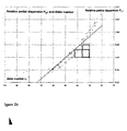
- This imaginary line is shown in Fig. 2a by a dotted line.
- glasses having a refractive index of between about 1.9 and about 2.2 and an Abbe number in a range of between about 30 and 40 tend to instability, so that it is very difficult to produce such glasses in higher amounts and with sufficient quality.
- glasses having a refractive index of between about 1.8 and about 2.1 and an Abbe number in a range of between about 30 and 55 tend to instability.
- refractive index refractive number
- Abbe number ⁇ d Abbe number ⁇ d
- relative partial dispersion for example P g,F
- the terms are used according to the definitions in " The properties of optical glass; Bach, Hans; Neuroth, Norbert (Ed.), Berlin (i.a.): Springer, 1995 . - (Schott series on glass and glass ceramics: science, technology, and applications; 1); XVII, 410 p. - 2., corr. print., 1998, XVII, 414 p.”.
- the relative partial dispersion plays an important role in the selection of an optical material. If it is desired to prepare approximately apochromatic optics, the combination of materials having approximately the same relative partial dispersion, but a high difference in the Abbe number is necessary. If the partial dispersion P g,F is plotted against the Abbe number ( Figure 2b), most glasses are on one line ("normal line"). Therefore materials are desired having a behaviour with a different combination of Abbe number and relative partial dispersion.
- polycrystalline ceramics have only been used in limited extent in optical applications till today.
- the Japanese Patent Publication JP 2000-203933 discloses the production of polycrystalline YAG by means of a special sintering process.
- the production of polycrystalline YAG of optical quality as a laser host material has been achieved, for example for doping with laser-active ions, such as for example Nd.
- US 3,640,887 describes the production of opto-ceramics on the basis of cubic oxides of the stoichiometry X 2 O 3 ("sesquioxides"). In an exemplary way, only optically active oxides are mentioned which are coloured owing to absorption bands in the visible (range of wave lengths of ca. 380 nm to 800 nm). As a sintering aid, i.a., ThO 2 is used. This one is not desired due to toxicity respectively radioactivity. The like belongs to US 3,545,987 .
- US 4,761,390 relates to a cover plate which substantially consists of a Y 2 O 3 ceramic.
- US 4,755,492 describes a transparent ceramic Y 2 O 3 as well as its production from powders which itself are produced by oxalate precipitation processes.
- the applications relate to discharging vessels for high pressure discharge lamps.
- US 4,098,612 describes transparent ceramics of mixed oxides of Y 2 O 3 and Al 2 O 3 for discharging vessels.
- Al 2 O 3 may be contained in an amount of up to 5 % by weight which results in the absence of a cubic structure.
- the like belongs to transparent ceramic Y 2 O 3 having high contents of La 2 O 3 from US 4,147,744 .
- US 4,571,312 as well as US 4,747,973 describe opto-ceramics of the system Y 2 O 3 -Gd 2 O 3 which, doped with lanthanides being optically active in the UV-VIS ( u ltra v iolet-visible range), are used as optically active scintillator materials for medicine technique.
- JP 2003-128465 respectively WO 06/03726 describe the production of opto-ceramics on the basis of Sc 2 O 3 respectively Lu 2 O 3 . To them are added optically active additives and thus, they are of interest for laser systems.
- the ceramic lens has to be connected with a glass lens, as well as the light scattering has to be reduced respectively distributed homogenously over the image detector by a special arrangement of this glass-ceramic-putty member in the optical mapping system.
- the object of the present invention is to provide a material having a high refractive index, a high Abbe number and/or an excellent, special relative partial dispersion, which parameters cannot be achieved with conventional glasses, single crystal materials or polycrystalline ceramics respectively materials.
- an optical element of the mentioned material should be provided which preferably has a high transparency in the visible and/or the infrared range of wave lengths.
- a mapping optic with an optical element which is formed of such a material should be provided.
- a mapping optic with approximately apochromatic mapping behaviour should be provided.
- Transparency in the visible means an internal transmittance (i.e. the light transmittance minus reflection losses) which is, within a window having a width of at least 200 nm, for example within a window of 400 to 600 nm, a window of 450 to 750 nm or preferably a window of 400 to 800 nm, in the range of the visible light having wave lengths of 380 nm to 800 nm, higher than 70 %, preferably > 80 %, more preferably > 90 %, particularly preferably > 95 %, at a layer thickness of 2 mm, preferably even at a layer thickness of 3 mm, particularly preferably at a layer thickness of 5 mm.
- an internal transmittance i.e. the light transmittance minus reflection losses
- Transparency in the infrared means an internal transmittance (i.e. the light transmittance minus reflection losses) which is, within a window having a width of at least 1,000 nm, for example within a window of 1,000 to 2,000 nm, a window of 1,500 to 2,500 nm or preferably a window of 3,000 to 4,000 nm, in the range of the infrared light having wave lengths of 800 nm to 5,000 nm, higher than 70 %, preferably > 80 %, more preferably > 90 %, particularly preferably > 95 %, at a layer thickness of 2 mm, preferably even at a layer thickness of 3 mm, particularly preferably at a layer thickness of 5 mm.
- an internal transmittance i.e. the light transmittance minus reflection losses
- the material has within a window of wave lengths of more than 200 nm between 5,000 nm and 8,000 nm at a thickness of 3 mm a transmittance (incl. reflection losses) of more than 20 %.
- the opto-ceramics according to the present invention are prepared by sintering of at least one oxide or a mixture of oxides of the type X 2 O 3 . Insofar the oxide is in pure form, X is In.
- X is selected from the group consisting of Y, Lu, Sc, Yb, In, Gd and La.
- a ceramic having cubic structure means a ceramic which consists of a crystal combination wherein the individual crystallites have a cubic structure.
- the material consists of a cubic phase of more than 95 %, further preferably > 98 %, even more preferably > 99 %.
- Mixtures of the above described oxides of the type X 2 O 3 with oxides of other stoichiometry, such as that of zirconium respectively hafnium, are also suitable as materials for the opto-ceramics according to the present invention, wherein here also the amount of the additives ZrO 2 respectively HfO 2 is chosen such that the cubic structure of the type Y 2 O 3 of the ceramic is maintained.
- the cubic crystals are packed as dense as possible as in a structure without imperfection.
- All mixed crystal phases have a cubic crystal structure which is isotypic to that of pure Y 2 O 3 .
- the present invention also comprises pure oxides of the type X 2 O 3 which have the cubic crystal structure analogous to that of Y 2 O 3 , namely In 2 O 3 and Yb 2 O 3 .
- the crystallites, from which the polycrystalline opto-ceramics are composed of, have cubic crystal structure. This results in isotropic optical behaviour without double refraction. They have dielectric behaviour, i.e. because of their cubic structure there are no permanent dipoles, and the material has the property of optical isotropy.
- the single crystallites are, as mentioned above, packed as dense as possible and regarding the theoretic densities values of at least 99 %, preferably at least 99.9 % and more preferred at least 99.99 % can be achieved.
- the ceramics according to the invention nearly do not comprise any pores.
- mapping optics with lenses of at least two different transparent materials, wherein at least one lens consists of an optical ceramic respectively is formed from that, as described above. Therefore, the invention is based on the finding that novel mapping properties can be provided by the use of two different transparent materials in one mapping optic, such as for example an objective.
- one aspect is also the possibility of achromatisation of the mapping optic with a relatively low number of refractive optical elements which cannot be realized with known glass kinds. For example in this case, there is contemplated the use of only three refractive optical elements in total for forming an objective having approximately apochromatic mapping properties.
- compact mapping optics having very low weight, low construction depth and with low costs for colour correction compared with the use of multi lens systems according to prior art may thus be achieved.
- the lenses may have pure refractive behaviour.
- the lenses may be arranged singly or with distances between them. Few of the lenses may in principle also be summarized to a group of lenses, for example as duplet of lenses, triplet of lenses etc.
- At least one of the lenses may also have diffractive structures which are for example stamped respectively pressed onto or written into the surface of the lens or a volume of the lens, for example in the form of Fresnel zone plates, diffraction gratings and also blazed diffraction gratings.
- the mapping optic comprises at least one lens of a glass; thus the mapping optic comprises a lens of the transparent opto-ceramic, as described above, and a lens of a glass which is adjusted to that.
- the relative partial dispersions (P g,F ) of the respective glass and the ceramic are approximately similar to one another; preferably the difference between them is less than about 10 %, wherein the difference of the Abbe numbers of the respective glass and the ceramic is higher than 10, preferably higher than 20.
- Approximately apochromatic mapping properties of the mapping optic may be achieved by simultaneously providing a comparatively high difference between the Abbe numbers with substantially identical relative partial dispersion.
- the opto-ceramics according to the present invention are transparent ceramics which have a refractive index of between about 1.85 and 2.0 and which have simultaneously an Abbe number in the range of between about 30 and 45. This provides the possibility of using novel material combinations for achromatisation of lens systems.
- opto-ceramics with Abbe numbers and relative partial dispersions in the above mentioned parameter ranges can be produced. This provides the possibility of using novel material combinations for achromatisation and/or apochromatisation of lens systems, wherein the opto-ceramics according to the present invention are formed as optical elements.
- mixtures of at least two oxides of the type X 2 O 3 wherein X is selected from the group consisting of Y, Lu, Sc, Yb, In, Gd and La, have good properties.
- Preferred mixtures are yttrium oxide with lutetium oxide, yttrium oxide with scandium oxide, yttrium oxide with indium oxide, lutetium oxide with scandium oxide, lutetium oxide with ytterbium oxide, lutetium oxide with indium oxide, lutetium oxide with gadolinium oxide, lutetium oxide with lanthanum oxide, scandium oxide with ytterbium oxide, scandium oxide with indium oxide, scandium oxide with gadolinium oxide, scandium oxide with lanthanum oxide, ytterbium oxide with indium oxide, ytterbium oxide with gadolinium oxide, ytterbium oxide with lanthanum oxide, indium oxide with gadolinium oxide, indium oxide with lanthanum oxide, yttrium oxide with ytterbium oxide, wherein ytterbium oxide is present in an amount of higher than 20 % by mol, yttrium oxide with gadolinium oxide, wherein gad
- More preferred mixtures are of, yttrium oxide with scandium oxide, yttrium oxide with indium oxide, lutetium oxide with scandium oxide, lutetium oxide with indium oxide, lutetium oxide with gadolinium oxide, lutetium oxide with lanthanum oxide, scandium oxide with ytterbium oxide, scandium oxide with indium oxide, scandium oxide with gadolinium oxide, scandium oxide with lanthanum oxide, ytterbium oxide with indium oxide, ytterbium oxide with gadolinium oxide, ytterbium oxide with lanthanum oxide, indium oxide with gadolinium oxide, indium oxide with lanthanum oxide, yttrium oxide with gadolinium oxide, wherein gadolinium oxide is present in an amount of higher than 20 % by mol, yttrium oxide with lanthanum oxide, wherein lanthanum oxide is present in an amount of higher than 10 % by mol.
- the proportions of the amounts of the individual oxides depend on the stability of the cubic basis phase. So for example Gd 2 O 3 can be doped into Yb 2 O 3 or Lu 2 O 3 in a maximum amount of ca. 80 % by mol, but into Y 2 O 3 in a maximum amount of only up to ca. 70 % by mol. Above these values, the crystal structure is formed as a monoclinic crystal system with low symmetry which is not desired according to the present invention. La 2 O 3 can be doped into Yb 2 O 3 , Lu 2 O 3 or Y 2 O 3 in a maximum amount of 20 % by mol. Also the oxides of other stoichiometries (such as zirconium and hafnium oxide) can be added, as long as the cubic structure is maintained.
- other stoichiometries such as zirconium and hafnium oxide
- the opto-ceramics according to the present invention are the following mixtures, based on the oxides each:
- the oxides which can be used according to the present invention form compounds which normally do not have any optical activity in the visible spectral range, i.e. at ca. 380 to 800 nm, i.e. light in this wave length range is neither absorbed nor emitted. Substantially, the ceramics are not coloured; no fluorescence is present in this case.
- the content of optically active impurities has to be reduced to a minimum.
- this is ⁇ 100 ppm, further preferably ⁇ 10 ppm, particularly preferably ⁇ 1 ppm and most preferably, the opto-ceramics are free of these ions, such as Pr, Nd, Sm, Eu, Tb, Dy, Ho, Er, Tm.
- these ions may be added in amounts such that the optical activity (efficiency of the laser action) is impaired which applies to amounts of 15 % by mol or higher.
- ZrO 2 or HfO 2 may be added in distinct amounts to the a.m. oxides respectively oxide mixtures, as mentioned above. For example, these are up to 50 % by mol of HfO 2 or ZrO 2 in Yb 2 O 3 or Lu 2 O 3 respectively up to 40 % by mol of HfO 2 or ZrO 2 in Sc 2 O 3 or Y 2 O 3 . Generally, the content of ZrO 2 should not exceed 55 % by mol.
- HfO 2 is possible as raw material, e.g. incorporated via ZrO 2 .
- ThO 2 is not suitable, because of toxicity respectively radioactivity.
- the refractive index is noticeably increased by the use of HfO 2 and/or ZrO 2 .
- optical properties such as transparency, refractive number, Abbe number and partial dispersion can be adjusted to the respective needs by a suitable combination of the oxides.
- the refractive values of the opto-ceramics according to the present invention are in the range of 1.80 and 2.1, further preferably 1.85 and 2.05 and particularly preferably 1.89 and 2.02, die Abbe number is between 30 and 45, preferably 33 to 40, and the relative partial dispersion (P g,F ) is in the range of 0.560 and 0.580, preferably of 0.565 and 0.575.
- Fig. 3 shows a group of lenses which can for example be inserted into a compact objective of an electronic apparatus, such as for example a mobile phone.
- the group of lenses comprises, from the side of the subject to the side of the image, a first lens L1, a lens aperture stop S, a second lens L2 and a third lens L3.
- Lens L1 has a positive refractive power and its convex surface is oriented to the side of the subject.
- the meniscus-shaped second lens L2 has a positive refractive power and its convex surface is oriented to the side of the subject.
- the third lens L3 has a negative refractive power and its concave surface is oriented to the side of the subject.
- the lens aperture stop S is arranged between the first lens L1 and the second lens L2 and substantially defines together with the diameter of the lenses the F number of the objective.
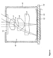
- Fig. 4 shows a typical set-up of an objective, for example as a mapping optic for a mobile phone, with a group of lenses according to Fig. 3.
- the objective had an F number of 2.88 with a focal length of 3.789 mm and a total length of the facility (up to the photo chip) of 5.55 mm.
- the material according to the present invention is the use in infrared applications.
- these materials have high transparency for wave lengths in the range of 800 nm up to 8,000 nm, but at least in the range of 800 up to 5,000 nm.
- the optical elements according to the present invention may be lenses of an optical ceramic of the above mentioned type which lead to mapping of both, the visible light (ca. 380 nm to ca. 800 nm) and also thermal radiation (infrared) of up to 8,000 nm.
- the production of the opto-ceramic is effected by the use of suitable powders.
- Methods for that are (co)precipitations, flame hydrolysis, gas condensation, laser ablation, plasma spray methods (CVS processes), sol gel methods, hydrothermal methods, combustions etc.
- the shape of the grain is preferably round-shaped respectively preferably spherical; the grains are only in loose contact with each other via van der Waals forces (soft agglomerates). Ideally, the grains are connected with each other via small bridges in the form of sintering necks.
- chemical precipitation reactions there is a high dependency of the grain fraction and grain shape of the precipitation conditions.
- a broad spectrum of different starting powders may be produced by the selection of the precipitation medium (carbonate precipitation, hydroxide precipitation, oxalate precipitations) of an e.g. nitrate or chloride solution of e.g. Y nitrate respectively yttrium chloride.
- Powders having different qualities and starting properties may also be achieved by different drying methods of the filter cake (simple drying on air, lyophilization, azeotropic distillation).
- additional parameters pH value, rate of rotation of the stirrer, temperature, precipitation volume etc.
- the purity of the powder is a substantial criterion.
- Each impurity may result in changed sintering conditions or in inhomogeneous distribution of the optical properties. Impurities may lead to the formation of liquid phases which in worst case may result in broad inhomogeneous grain boundary regions. However the formation of intergranular phases (amorph or cryst.) should be avoided, because of this differences of the refractive value may be the result which in the case of light passage leads to scattering losses.
- hard agglomerates i.e. primary particles which have multiply formed bridges during the precipitation respectively the calcination respectively are "fused” together due to that in a more or less scope, is possible according to the choice of the method.
- So e.g. J. Mouzon describes in a published Licenciate Thesis "Synthesis of Yb:Y 2 O 3 nanoparticles and Fabrication of Transparent Polycrystalline Yttria Ceramic", Lulea University of Technology, Int. No. 2005:29, that for the avoidance of intragranular pores, i.e. pores inside the grain, differential sintering is advantageous.
- hard agglomerates i.e. the primary particles within an agglomerate first are sintering into a dense state, wherein remaining pores are preferably located in the grain boundary region. Those could be removed from the structure by the method of "hot isostatic pressing".
- the powders are processed in different ways due to the forming. Normally, the powder is ground with the aim a) to disintegrate yet present agglomerates and b) to homogenize the powders during the addition of additives.
- the grinding may be performed in dry or wet condition, with the latter being e.g. alcohols or media on water basis. The times of grinding may be up to 24 hours, but should be selected such that no abrasion of the grinding bodies (Al 2 O 3 , ZrO 2 ) respectively of the lining of the grinding drum can take place. Ring scission, Attritor, ball grinders etc. are suitable as grinding mills.
- liquid alcohols respectively liquid hydrocarbons, such as heptanes or others may be used.
- the drying of the mixtures may again be carried out on air at low temperatures, wherein in the most convenient case the grinding suspension is dried by the means of spray drying. In this case, granules having defined size and quality can be produced.
- spray drying the use of binders is recommended, wherein the spray drying preferably results in soft agglomerates.
- the size of the agglomerates should not exceed 100 ⁇ m, wherein agglomerates in the order of 10 to 50 ⁇ m are convenient and agglomerates ⁇ 10 ⁇ m are ideal. Also lyophilization or turbulent flow drying are possible.
- the nanopowder respectively the nanopowder agglomerate has to be pressed.
- the powder mixture has to be dispersed in suitable liquefiers.
- suitable liquefiers for example, Darvan, Dolapix, polyaryl acids, polyacrylic acids, ammonium oxalate monohydrate, oxalic acid, sorbite ammonium citrate or others are suitable.
- organic binders of the type polyolefin e.g. HOSTAMOND ® of the company Clariant
- catalytically degrading binders e.g. of the type CATAMOLD ® of the company BASF
- Vacuum sintering allows the removal of open porosity from the compact powder.
- it can also be sintered in specific atmospheres (He, hydrogen (dry or wet), N 2 , Ar).
- the growth of the grains is not too fast and uncontrolled.
- the aim is, not to incorporate pores into the grains. For that, e.g. the sintering temperatures can be kept very low.
- the sample is yet opaque due to the high pore density, but the pores are closed.
- the closed porosity between the grain boundaries may be pressed out of the structure by a subsequent HIP process.
- Exemplary conditions are 1,500°C to 1,800°C, pressures between 100 MPa (1,000 bar) and 200 MPa (2,000 bar). Tempering times of between 1 and 10 hours (without heating and cooling time) are common. W or Mo, optionally also graphite may be used as a heating element.
- Argon may be used as a pressure medium.
- the sample may be encapsulated respectively embedded in a powder of its own kind to avoid the solution of Ar in the grain boundaries, e.g. in glass-like intermediate phases.
- Intragranular fine porosity can also be reduced by a special process run. This is effected by targeted growth of the grains which takes place in such a manner that newly build grain boundaries "grow beyond" the region of the pore volume enclosed in the grain.
- the sample is again subjected to a sintering process after the HIP process.
- vacuum hot pressing instead of vacuum sintering and the subsequent HIP process, also the combined process of "vacuum hot pressing" may be used.
- High purity Y 2 O 3 , La 2 O 3 and HfO 2 powders were used as starting material.
- the powders were mixed with additives and binders and ball milled for 12 h in ethanol. Then, the alcohol solvent was removed by drying the milled slurry on a hot plate. The so-obtained powder was pressed with low pressure into required shapes in a metal mould and then cold isostatically pressed at 98 MPa.
- Transparent Y 2 O 3 ceramics were obtained after sintering under vacuum (1x10 -3 Pa) at 1700°C for 3h followed by hot isostatic pressing at 1780°C for 2h at a pressure of 196 Mpa in Ar atmosphere.
- T in-line I in - line
- I 0 10 - ( k in - line ) d
- I in-line and I 0 are the specularly transmitted intensity leaving the sample and the incident intensity, respectively and k in-line is the absorption coefficient.
Landscapes
- Chemical & Material Sciences (AREA)
- Engineering & Computer Science (AREA)
- Ceramic Engineering (AREA)
- Manufacturing & Machinery (AREA)
- Materials Engineering (AREA)
- Structural Engineering (AREA)
- Organic Chemistry (AREA)
- Inorganic Chemistry (AREA)
- Composite Materials (AREA)
- Compositions Of Oxide Ceramics (AREA)
- Diffracting Gratings Or Hologram Optical Elements (AREA)
- Glass Compositions (AREA)
Abstract
Description
- The present invention relates to opto-ceramics and refractive, transmittive or diffractive optical elements prepared therefrom. These opto-ceramics and optical elements are transmittive for visible light and/or for infrared radiation. The opto-ceramics consist of a crystal combination wherein the single crystallites have a cubic structure of the type Y2O3, comprising alternatively the oxide In2O3, or a mixture of two or more oxides of the type X2O3, wherein X is selected from the group consisting of Y, Lu, Sc, Yb, In, Gd and La.
- Also mixtures of X2O3 with oxides having a different stoichiometry such as zirconium and hafnium oxide are possible, as long as the cubic structure of the ceramic will be maintained.
- In the following the ceramic is also referred to as opto-ceramic. According to the present invention, an opto-ceramic (or ceramic) is, as mentioned above, highly transparent, poly crystalline single phase material comprising an oxide. Opto-ceramics are to be understood as a particular sub group of a ceramic. "Single phase" means that more than 95 % by weight, preferably at least 97 % by weight and more preferably 99 % by weight and most preferred 99.5 to 99.9 % by weight are in the crystalline form of the intended composition.
- The optical elements which may be prepared from said opto-ceramics are particularly suitable for use in mapping optics, such as for example objectives having reduced chromatic aberrations, in particular with approximately apochromatic mapping behaviour. The optical elements of the opto-ceramic according to the present invention may be applied in lens systems in combination with lenses of glass, but also with other ceramic lenses, in particular also in digital cameras, mobile phone cameras, in the field of microscopy, microlithography, optical data storage or other applications in the field of consumer or industry applications.
- The main target in the development of mapping optics is to attain a sufficient optical quality with a compact set-up of the optic which is as light as possible. In particular for applications in the field of digital image detection in electronic apparatuses, such as for example digital cameras, objectives of mobile phones and the like, the mapping optic has to be constructed very small and lightweight. In other words, the total amount of lenses has to be minimal. This requires transparent materials with high refractive index and a dispersion which is as low as possible to thus allow the design of very compact mapping optics having approximately apochromatic mapping behaviour.
- In the case of microscopy, nearly diffraction-limited mapping optics are necessary, for the ocular as well as the objective.
- In the field of defence, transparent optics are required which have high transmittance in the visible (380 to 800 nm) and also the infrared spectral range, up to 8,000 nm, ideally up to 10,000 nm and, in addition, which are resistant against influences from outside, such as mechanical action, shock, temperature, change of temperature, pressure etc.
- For many other technologies the same applies, such as for example for digital projection and further display techniques. But also in predominantly monochromatic applications, such as the optical storage technologies, compact systems can be realized by means of materials having high refractive index.
- At the moment, the development of mapping optics is limited by the optical parameters of the available materials. By the available techniques of glass melting and glass forming, only such kinds of glasses having high quality can be produced which are in an Abbe diagram plotting the refractive number against the Abbe number below a line which approximately passes through the points Abbe number = 80/refractive index = 1.7 and Abbe number = 10/refractive index = 2.0. This imaginary line is shown in Fig. 2a by a dotted line. In more detail, glasses having a refractive index of between about 1.9 and about 2.2 and an Abbe number in a range of between about 30 and 40 tend to instability, so that it is very difficult to produce such glasses in higher amounts and with sufficient quality. Also glasses having a refractive index of between about 1.8 and about 2.1 and an Abbe number in a range of between about 30 and 55 tend to instability.
- The definitions of refractive index (refractive number) nd, Abbe number νd and relative partial dispersion (for example Pg,F) are in principle well known by a person skilled in the art and may be defined in more detail by the means of specialized literature. In the sense of the present invention, the terms are used according to the definitions in "The properties of optical glass; Bach, Hans; Neuroth, Norbert (Ed.), Berlin (i.a.): Springer, 1995. - (Schott series on glass and glass ceramics: science, technology, and applications; 1); XVII, 410 p. - 2., corr. print., 1998, XVII, 414 p.".
- In addition to refractive number and Abbe number, the relative partial dispersion plays an important role in the selection of an optical material. If it is desired to prepare approximately apochromatic optics, the combination of materials having approximately the same relative partial dispersion, but a high difference in the Abbe number is necessary. If the partial dispersion Pg,F is plotted against the Abbe number (Figure 2b), most glasses are on one line ("normal line"). Therefore materials are desired having a behaviour with a different combination of Abbe number and relative partial dispersion.
- At the moment, materials which are above the before mentioned imaginary line in an Abbe diagram are exclusively single crystals or polycrystalline materials. However, the production of single crystals by means of the known crystal-pulling processes is extremely costly and has enormous limitations with respect to the chemical composition. Furthermore, for most applications crystals cannot be produced close to the final format, so that this results in an enormous effort of post-processing. Although polycrystalline ceramics can be produced with a broader range of compositions, normally they have insufficient optical qualities, in particular with respect to the homogeneity of the refractive index and the transparency. Till today, only few ranges of compositions and structure types are known, in which transparent ceramics having sufficient optical quality can be produced.
- Therefore, polycrystalline ceramics have only been used in limited extent in optical applications till today. Thus for example, the
Japanese Patent Publication JP 2000-203933 - In
US Patent 6,908,872 a translucent ceramic is described which uses barium oxide as an oxide which has to be present in the ceramic. The thus obtained ceramics have a perovskite structure and are para-electric. However, ceramics containing such barium-containing phases having perovskite structure often have an insufficient optical mapping quality. This is a result of the tendency of many perovskites to form distorted ferro-electric crystal structures and thus to loos their optical isotropy. Inter alia, this results in undesired double refraction of the crystals, from which the ceramic is built, and, in addition, the transmittance in the range of blue light (about 380 nm) is insufficient. -
US 3,640,887 describes the production of opto-ceramics on the basis of cubic oxides of the stoichiometry X2O3 ("sesquioxides"). In an exemplary way, only optically active oxides are mentioned which are coloured owing to absorption bands in the visible (range of wave lengths of ca. 380 nm to 800 nm). As a sintering aid, i.a., ThO2 is used. This one is not desired due to toxicity respectively radioactivity. The like belongs toUS 3,545,987 . -
US 4,761,390 relates to a cover plate which substantially consists of a Y2O3 ceramic. - Also
US 4,755,492 describes a transparent ceramic Y2O3 as well as its production from powders which itself are produced by oxalate precipitation processes. The applications relate to discharging vessels for high pressure discharge lamps. -
US 4,098,612 describes transparent ceramics of mixed oxides of Y2O3 and Al2O3 for discharging vessels. Al2O3 may be contained in an amount of up to 5 % by weight which results in the absence of a cubic structure. The like belongs to transparent ceramic Y2O3 having high contents of La2O3 fromUS 4,147,744 .US 4,571,312 as well asUS 4,747,973 describe opto-ceramics of the system Y2O3-Gd2O3 which, doped with lanthanides being optically active in the UV-VIS (ultraviolet-visible range), are used as optically active scintillator materials for medicine technique. -
JP 2003-128465 WO 06/03726 -
US 2006-061880 respectivelyUS 2006-062569 describe the combination of optical mapping systems consisting of at least one lens of ceramic and additional lenticular components of glass, but the advantageous effect of the ceramic (owing to e.g. a convenient dispersion behaviour) for the whole system is not mentioned. The ceramic lens with extremely high refractive index (nd = 2.08) is in direct contact with a glass lens (nd = 1.62). Particular and thus costly measures have to be taken to avoid the problem of light scattering associated with the high difference in nd. Thus e.g. inUS 2006-062569 , the ceramic lens has to be connected with a glass lens, as well as the light scattering has to be reduced respectively distributed homogenously over the image detector by a special arrangement of this glass-ceramic-putty member in the optical mapping system. - The object of the present invention is to provide a material having a high refractive index, a high Abbe number and/or an excellent, special relative partial dispersion, which parameters cannot be achieved with conventional glasses, single crystal materials or polycrystalline ceramics respectively materials. According to a further aspect of the present invention, further an optical element of the mentioned material should be provided which preferably has a high transparency in the visible and/or the infrared range of wave lengths. According to a further aspect of the present invention, a mapping optic with an optical element which is formed of such a material should be provided. According to a further aspect of the present invention, in particular a mapping optic with approximately apochromatic mapping behaviour should be provided.
- Transparency in the visible means an internal transmittance (i.e. the light transmittance minus reflection losses) which is, within a window having a width of at least 200 nm, for example within a window of 400 to 600 nm, a window of 450 to 750 nm or preferably a window of 400 to 800 nm, in the range of the visible light having wave lengths of 380 nm to 800 nm, higher than 70 %, preferably > 80 %, more preferably > 90 %, particularly preferably > 95 %, at a layer thickness of 2 mm, preferably even at a layer thickness of 3 mm, particularly preferably at a layer thickness of 5 mm.
- Transparency in the infrared means an internal transmittance (i.e. the light transmittance minus reflection losses) which is, within a window having a width of at least 1,000 nm, for example within a window of 1,000 to 2,000 nm, a window of 1,500 to 2,500 nm or preferably a window of 3,000 to 4,000 nm, in the range of the infrared light having wave lengths of 800 nm to 5,000 nm, higher than 70 %, preferably > 80 %, more preferably > 90 %, particularly preferably > 95 %, at a layer thickness of 2 mm, preferably even at a layer thickness of 3 mm, particularly preferably at a layer thickness of 5 mm.
- Ideally, the material has within a window of wave lengths of more than 200 nm between 5,000 nm and 8,000 nm at a thickness of 3 mm a transmittance (incl. reflection losses) of more than 20 %.
- These and other objects are solved according to the present invention by the opto-ceramics according to
claim 1 as well as by optical elements according toclaim 10 and a mapping optic having the features according toclaim 11. Additional advantageous embodiments are the subject matter of the dependent claims. - The opto-ceramics according to the present invention are prepared by sintering of at least one oxide or a mixture of oxides of the type X2O3. Insofar the oxide is in pure form, X is In.
- If a mixture of two or more oxides of the type X2O3 is present, X is selected from the group consisting of Y, Lu, Sc, Yb, In, Gd and La.
- In this case it is essential, that the ratios of the components of the mixture are chosen such that the cubic structure type of the type Y2O3 is maintained. In the sense of the invention, a ceramic having cubic structure means a ceramic which consists of a crystal combination wherein the individual crystallites have a cubic structure. Preferably, the material consists of a cubic phase of more than 95 %, further preferably > 98 %, even more preferably > 99 %.
- Mixtures of the above described oxides of the type X2O3 with oxides of other stoichiometry, such as that of zirconium respectively hafnium, are also suitable as materials for the opto-ceramics according to the present invention, wherein here also the amount of the additives ZrO2 respectively HfO2 is chosen such that the cubic structure of the type Y2O3 of the ceramic is maintained. Preferably, the cubic crystals are packed as dense as possible as in a structure without imperfection.
- All mixed crystal phases have a cubic crystal structure which is isotypic to that of pure Y2O3.
- As mentioned above, the present invention also comprises pure oxides of the type X2O3 which have the cubic crystal structure analogous to that of Y2O3, namely In2O3 and Yb2O3.
- The crystallites, from which the polycrystalline opto-ceramics are composed of, have cubic crystal structure. This results in isotropic optical behaviour without double refraction. They have dielectric behaviour, i.e. because of their cubic structure there are no permanent dipoles, and the material has the property of optical isotropy. The single crystallites are, as mentioned above, packed as dense as possible and regarding the theoretic densities values of at least 99 %, preferably at least 99.9 % and more preferred at least 99.99 % can be achieved. Hence, the ceramics according to the invention (opto-ceramics) nearly do not comprise any pores.
- According to a further aspect of the present invention which may also be independently claimed, there is provided a mapping optic with lenses of at least two different transparent materials, wherein at least one lens consists of an optical ceramic respectively is formed from that, as described above. Therefore, the invention is based on the finding that novel mapping properties can be provided by the use of two different transparent materials in one mapping optic, such as for example an objective. In particular, one aspect is also the possibility of achromatisation of the mapping optic with a relatively low number of refractive optical elements which cannot be realized with known glass kinds. For example in this case, there is contemplated the use of only three refractive optical elements in total for forming an objective having approximately apochromatic mapping properties. Overall, according to the present invention compact mapping optics having very low weight, low construction depth and with low costs for colour correction compared with the use of multi lens systems according to prior art may thus be achieved.
- In this case, according to a further aspect of the present invention the lenses may have pure refractive behaviour. The lenses may be arranged singly or with distances between them. Few of the lenses may in principle also be summarized to a group of lenses, for example as duplet of lenses, triplet of lenses etc.
- According to a further alternative aspect of the present invention, at least one of the lenses may also have diffractive structures which are for example stamped respectively pressed onto or written into the surface of the lens or a volume of the lens, for example in the form of Fresnel zone plates, diffraction gratings and also blazed diffraction gratings.
- According to a further preferable embodiment, the mapping optic comprises at least one lens of a glass; thus the mapping optic comprises a lens of the transparent opto-ceramic, as described above, and a lens of a glass which is adjusted to that.
- According to a further aspect of the present invention, in this case the relative partial dispersions (Pg,F) of the respective glass and the ceramic are approximately similar to one another; preferably the difference between them is less than about 10 %, wherein the difference of the Abbe numbers of the respective glass and the ceramic is higher than 10, preferably higher than 20. Approximately apochromatic mapping properties of the mapping optic may be achieved by simultaneously providing a comparatively high difference between the Abbe numbers with substantially identical relative partial dispersion.
- In the following, the invention will be described in exemplary way and with reference to the accompanying figures from which further features, advantages and objects to be solved will follow.
- Fig. 1
- shows four examples for optical elements which can be produced from the optoceramics according to the present invention;
- Fig.
- 2a presents an Abbe diagram wherein the properties of different glasses and optoceramics according to the present invention are summarized;
- Fig. 2b
- is a diagram which summarizes the relation of the positions (relative partial dispersion against Abbe number) of glasses and opto-ceramics according to the present invention;
- Fig. 3
- shows a mapping optic according to an embodiment example of the present invention.
- Fig. 4
- shows a compact image detection facility with a mapping optic according to Fig. 3.
- In the Abbe diagram according to Fig. 2a, points marked with a circular symbol represent in an exemplary way kinds of glasses which can be prepared in high optical quality by the glass melting techniques which are available today. As is clearly obvious from Fig. 2a, with the present techniques of glass melting and glass forming glasses which are above the dotted line which passes through the points Abbe number = 80/refractive index = 1.7 and Abbe number = 10/refractive index = 2.0 can only be produced with limitations. In particular, glasses having a refractive index in the range of between 1.85 and 2.1 in combination with an Abbe number of between about 30 and 45 are instable (see rectangle in Fig. 2a). As explained below, the opto-ceramics according to the present invention are transparent ceramics which have a refractive index of between about 1.85 and 2.0 and which have simultaneously an Abbe number in the range of between about 30 and 45. This provides the possibility of using novel material combinations for achromatisation of lens systems.
- In the diagram according to Fig. 2b, the Abbe number of various glasses and single crystalline materials are plotted against the relative partial dispersion (Pg,F). As can be clearly seen in Fig. 2b, the combination of an Abbe number of between about 30 and 42 and a relative partial dispersion of between about 0.56 and 0.58 cannot be achieved with glasses (see rectangle in Fig. 2b).
- As set forth below in more detail, according to the present invention opto-ceramics with Abbe numbers and relative partial dispersions in the above mentioned parameter ranges can be produced. This provides the possibility of using novel material combinations for achromatisation and/or apochromatisation of lens systems, wherein the opto-ceramics according to the present invention are formed as optical elements.
- Within the composition range, different excellent mixtures of the oxides result in cubic phases which are particularly suitable for the production of an opto-ceramic according to the present invention. So for example, mixtures of at least two oxides of the type X2O3, wherein X is selected from the group consisting of Y, Lu, Sc, Yb, In, Gd and La, have good properties.
- Preferred mixtures are yttrium oxide with lutetium oxide, yttrium oxide with scandium oxide, yttrium oxide with indium oxide, lutetium oxide with scandium oxide, lutetium oxide with ytterbium oxide, lutetium oxide with indium oxide, lutetium oxide with gadolinium oxide, lutetium oxide with lanthanum oxide, scandium oxide with ytterbium oxide, scandium oxide with indium oxide, scandium oxide with gadolinium oxide, scandium oxide with lanthanum oxide, ytterbium oxide with indium oxide, ytterbium oxide with gadolinium oxide, ytterbium oxide with lanthanum oxide, indium oxide with gadolinium oxide, indium oxide with lanthanum oxide, yttrium oxide with ytterbium oxide, wherein ytterbium oxide is present in an amount of higher than 20 % by mol, yttrium oxide with gadolinium oxide, wherein gadolinium oxide is present in an amount of higher than 20 % by mol, yttrium oxide with lanthanum oxide, wherein lanthanum oxide is present in an amount of higher than 10 % by mol.
- More preferred mixtures are of, yttrium oxide with scandium oxide, yttrium oxide with indium oxide, lutetium oxide with scandium oxide, lutetium oxide with indium oxide, lutetium oxide with gadolinium oxide, lutetium oxide with lanthanum oxide, scandium oxide with ytterbium oxide, scandium oxide with indium oxide, scandium oxide with gadolinium oxide, scandium oxide with lanthanum oxide, ytterbium oxide with indium oxide, ytterbium oxide with gadolinium oxide, ytterbium oxide with lanthanum oxide, indium oxide with gadolinium oxide, indium oxide with lanthanum oxide, yttrium oxide with gadolinium oxide, wherein gadolinium oxide is present in an amount of higher than 20 % by mol, yttrium oxide with lanthanum oxide, wherein lanthanum oxide is present in an amount of higher than 10 % by mol.
- The proportions of the amounts of the individual oxides depend on the stability of the cubic basis phase. So for example Gd2O3 can be doped into Yb2O3 or Lu2O3 in a maximum amount of ca. 80 % by mol, but into Y2O3 in a maximum amount of only up to ca. 70 % by mol. Above these values, the crystal structure is formed as a monoclinic crystal system with low symmetry which is not desired according to the present invention. La2O3 can be doped into Yb2O3, Lu2O3 or Y2O3 in a maximum amount of 20 % by mol. Also the oxides of other stoichiometries (such as zirconium and hafnium oxide) can be added, as long as the cubic structure is maintained.
- Preferable for the opto-ceramics according to the present invention are the following mixtures, based on the oxides each:
- Y-Lu, Y-Sc, Y-In;
- Lu-Sc, Lu-Yb, Lu-In, Lu-Gd, Lu-La;
- Sc-Yb, Sc-In, Sc-Gd, Sc-La;
- Yb-In, Yb-Gd, Yb-La;
- In-Gd, In-La.
- Possible are also mixtures of yttrium oxide with ytterbium oxide, wherein ytterbium oxide is present in an amount of higher than 20 % by mol, preferably higher than 30 % by mol and further preferably higher than 40 % by mol; yttrium oxide with gadolinium oxide, wherein gadolinium oxide is present in an amount of higher than 20 % by mol, preferably higher than 30 % by mol and further preferably higher than 40 % by mol; yttrium oxide with lanthanum oxide, wherein lanthanum oxide is present in an amount of higher than 10 % by mol, preferably higher than 20 % by mol.
- Alternatives with three or more than three oxide constituents are also possible.
- The oxides which can be used according to the present invention form compounds which normally do not have any optical activity in the visible spectral range, i.e. at ca. 380 to 800 nm, i.e. light in this wave length range is neither absorbed nor emitted. Substantially, the ceramics are not coloured; no fluorescence is present in this case.
- For a series of passive optical elements, possible fluorescence has to be suppressed in a targeted way. This can be guaranteed by the use of raw materials with especially high purity. According to an embodiment, the content of optically active impurities (for example active ions of the group of rare earths or transition metals) has to be reduced to a minimum. Preferably, this is < 100 ppm, further preferably < 10 ppm, particularly preferably < 1 ppm and most preferably, the opto-ceramics are free of these ions, such as Pr, Nd, Sm, Eu, Tb, Dy, Ho, Er, Tm.
- According to an alternative embodiment, these ions may be added in amounts such that the optical activity (efficiency of the laser action) is impaired which applies to amounts of 15 % by mol or higher.
- A prerequisite for that is that for the distinct application self-colour or fluorescence does not play a role. As long as this is the case, also further element oxides of the lanthanides series may be used, for example it may be supplemented with Tb2O3, Dy2O3, Er2O3, Ho2O3, Tm2O3. The last mentioned oxides also form cubic phases as pure oxides.
- ZrO2 or HfO2 may be added in distinct amounts to the a.m. oxides respectively oxide mixtures, as mentioned above. For example, these are up to 50 % by mol of HfO2 or ZrO2 in Yb2O3 or Lu2O3 respectively up to 40 % by mol of HfO2 or ZrO2 in Sc2O3 or Y2O3. Generally, the content of ZrO2 should not exceed 55 % by mol.
- HfO2 is possible as raw material, e.g. incorporated via ZrO2. ThO2 is not suitable, because of toxicity respectively radioactivity.
- The refractive index is noticeably increased by the use of HfO2 and/or ZrO2.
- The optical properties, such as transparency, refractive number, Abbe number and partial dispersion can be adjusted to the respective needs by a suitable combination of the oxides.
- Preferably, the refractive values of the opto-ceramics according to the present invention are in the range of 1.80 and 2.1, further preferably 1.85 and 2.05 and particularly preferably 1.89 and 2.02, die Abbe number is between 30 and 45, preferably 33 to 40, and the relative partial dispersion (Pg,F) is in the range of 0.560 and 0.580, preferably of 0.565 and 0.575.
- Fig. 3 shows a group of lenses which can for example be inserted into a compact objective of an electronic apparatus, such as for example a mobile phone. According to Fig. 3, the group of lenses comprises, from the side of the subject to the side of the image, a first lens L1, a lens aperture stop S, a second lens L2 and a third lens L3. Lens L1 has a positive refractive power and its convex surface is oriented to the side of the subject. The meniscus-shaped second lens L2 has a positive refractive power and its convex surface is oriented to the side of the subject. The third lens L3 has a negative refractive power and its concave surface is oriented to the side of the subject. The lens aperture stop S is arranged between the first lens L1 and the second lens L2 and substantially defines together with the diameter of the lenses the F number of the objective.
- Fig. 4 shows a typical set-up of an objective, for example as a mapping optic for a mobile phone, with a group of lenses according to Fig. 3. In an embodiment example, the objective had an F number of 2.88 with a focal length of 3.789 mm and a total length of the facility (up to the photo chip) of 5.55 mm.
- An additional use of the material according to the present invention is the use in infrared applications. Preferably, these materials have high transparency for wave lengths in the range of 800 nm up to 8,000 nm, but at least in the range of 800 up to 5,000 nm. Absolutely preferably, the optical elements according to the present invention may be lenses of an optical ceramic of the above mentioned type which lead to mapping of both, the visible light (ca. 380 nm to ca. 800 nm) and also thermal radiation (infrared) of up to 8,000 nm.
- Applications for that are windows and lenses for so called "Forward looking Infrared" which are transmittive for infrared, for aeroplanes for antiballistic missile defence, cover crowns of antiballistic missiles for infrared wave lengths of up to 8,000 nm. In this case, it is particularly convenient that at the same time the material has high transmittance for both, visible and also infrared light. This facilitates uses in the field of defence.
- Production of opto-ceramics of the type "X2O3"
- The production of the opto-ceramic is effected by the use of suitable powders. Methods for that are (co)precipitations, flame hydrolysis, gas condensation, laser ablation, plasma spray methods (CVS processes), sol gel methods, hydrothermal methods, combustions etc. In view of high packing densities, the shape of the grain is preferably round-shaped respectively preferably spherical; the grains are only in loose contact with each other via van der Waals forces (soft agglomerates). Ideally, the grains are connected with each other via small bridges in the form of sintering necks. Regarding to chemical precipitation reactions, there is a high dependency of the grain fraction and grain shape of the precipitation conditions. Thus a broad spectrum of different starting powders may be produced by the selection of the precipitation medium (carbonate precipitation, hydroxide precipitation, oxalate precipitations) of an e.g. nitrate or chloride solution of e.g. Y nitrate respectively yttrium chloride. Powders having different qualities and starting properties (e.g. specific surface) may also be achieved by different drying methods of the filter cake (simple drying on air, lyophilization, azeotropic distillation). Furthermore, a great amount of additional parameters (pH value, rate of rotation of the stirrer, temperature, precipitation volume etc.) have to be considered during the precipitations.
- The purity of the powder is a substantial criterion. Each impurity may result in changed sintering conditions or in inhomogeneous distribution of the optical properties. Impurities may lead to the formation of liquid phases which in worst case may result in broad inhomogeneous grain boundary regions. However the formation of intergranular phases (amorph or cryst.) should be avoided, because of this differences of the refractive value may be the result which in the case of light passage leads to scattering losses.
- The use also of hard agglomerates, i.e. primary particles which have multiply formed bridges during the precipitation respectively the calcination respectively are "fused" together due to that in a more or less scope, is possible according to the choice of the method. So e.g. J. Mouzon describes in a published Licenciate Thesis "Synthesis of Yb:Y2O3 nanoparticles and Fabrication of Transparent Polycrystalline Yttria Ceramic", Lulea University of Technology, Int. No. 2005:29, that for the avoidance of intragranular pores, i.e. pores inside the grain, differential sintering is advantageous. This will be guaranteed by hard agglomerates, i.e. the primary particles within an agglomerate first are sintering into a dense state, wherein remaining pores are preferably located in the grain boundary region. Those could be removed from the structure by the method of "hot isostatic pressing".
- Furthermore, in the production of (co)precipitated powders there is the possibility of reducing the tendency to agglomeration by the targeted addition of agents. So the necessity of a grinding process is avoided. For that, there is the possibility of adding NH4OH before the calcination of a precipitated oxalate suspension.
- The powders are processed in different ways due to the forming. Normally, the powder is ground with the aim a) to disintegrate yet present agglomerates and b) to homogenize the powders during the addition of additives. The grinding may be performed in dry or wet condition, with the latter being e.g. alcohols or media on water basis. The times of grinding may be up to 24 hours, but should be selected such that no abrasion of the grinding bodies (Al2O3, ZrO2) respectively of the lining of the grinding drum can take place. Ring scission, Attritor, ball grinders etc. are suitable as grinding mills. As a medium for example water, liquid alcohols respectively liquid hydrocarbons, such as heptanes or others may be used.
- The drying of the mixtures may again be carried out on air at low temperatures, wherein in the most convenient case the grinding suspension is dried by the means of spray drying. In this case, granules having defined size and quality can be produced. In the case of spray drying, the use of binders is recommended, wherein the spray drying preferably results in soft agglomerates. The size of the agglomerates should not exceed 100 µm, wherein agglomerates in the order of 10 to 50 µm are convenient and agglomerates < 10 µm are ideal. Also lyophilization or turbulent flow drying are possible.
- Occasionally, also additives are required, if the nanopowder respectively the nanopowder agglomerate has to be pressed. For forming by casting, e.g. slip casting, pressure casting, centrifugal casting, the powder mixture has to be dispersed in suitable liquefiers. For that for example, Darvan, Dolapix, polyaryl acids, polyacrylic acids, ammonium oxalate monohydrate, oxalic acid, sorbite ammonium citrate or others are suitable.
- For plastic forming (extruding, injection moulding, heat casting), organic binders of the type polyolefin, e.g. HOSTAMOND® of the company Clariant, or catalytically degrading binders, e.g. of the type CATAMOLD® of the company BASF, have to be introduced into the powder and have to be homogenized in suitable form.
- Pressing allows a quick and cheap forming.
- For slip casting, the use of moulds of gypsum is recommended.
- Vacuum sintering allows the removal of open porosity from the compact powder. The vacuum conditions are above 10-3 mbar (= 10-3 hPa), wherein preferably pressures between 10-5 and 10-6 mbar (= 10-5 and 10-6 hPa) are used. The sintering conditions vary according to the material, wherein for example regimes, such as T = 1,500°C to 1,800°C and sintering times of between 1 and 10 hours should be mentioned.
- Alternatively, it can also be sintered in specific atmospheres (He, hydrogen (dry or wet), N2, Ar).
- In the case of vacuum sintering, it is important that the growth of the grains is not too fast and uncontrolled. The aim is, not to incorporate pores into the grains. For that, e.g. the sintering temperatures can be kept very low. Optionally, thereafter the sample is yet opaque due to the high pore density, but the pores are closed.
- The closed porosity between the grain boundaries may be pressed out of the structure by a subsequent HIP process. Exemplary conditions are 1,500°C to 1,800°C, pressures between 100 MPa (1,000 bar) and 200 MPa (2,000 bar). Tempering times of between 1 and 10 hours (without heating and cooling time) are common. W or Mo, optionally also graphite may be used as a heating element.
- Argon may be used as a pressure medium. The sample may be encapsulated respectively embedded in a powder of its own kind to avoid the solution of Ar in the grain boundaries, e.g. in glass-like intermediate phases.
- By the latter, discolouration by reduction of material at the surface respectively contamination of the sample with constituents of the heating element which are inside the furnace chamber can be avoided, wherein thus "post tempering" on air is not necessary. If yet required, it should be conducted on air or in oxygen. Exemplary conditions are 1 to 48 hours at up to 1,400°C.
- Intragranular fine porosity can also be reduced by a special process run. This is effected by targeted growth of the grains which takes place in such a manner that newly build grain boundaries "grow beyond" the region of the pore volume enclosed in the grain.
- For that, the sample is again subjected to a sintering process after the HIP process.
- Instead of vacuum sintering and the subsequent HIP process, also the combined process of "vacuum hot pressing" may be used.
- High purity Y2O3, La2O3 and HfO2 powders were used as starting material. The powders were mixed with additives and binders and ball milled for 12 h in ethanol. Then, the alcohol solvent was removed by drying the milled slurry on a hot plate. The so-obtained powder was pressed with low pressure into required shapes in a metal mould and then cold isostatically pressed at 98 MPa.
- Transparent Y2O3 ceramics were obtained after sintering under vacuum (1x10⁻³Pa) at 1700°C for 3h followed by hot isostatic pressing at 1780°C for 2h at a pressure of 196 Mpa in Ar atmosphere.
- The Interaction of light with an optically transparent material is given by the addition of Reflection, Absorption, Scattering and specular transmission. The reflection losses are inherent to the material due to Snells law. The total amount of light emerging from a material is termed as "total transmittance", while its specularly transmitted portion is termed as in-line transmittance (Tin-line), after taking into account scattering as possible loss mechanism.

Where Iin-line and I0 are the specularly transmitted intensity leaving the sample and the incident intensity, respectively and kin-line is the absorption coefficient. A graphic representation can be seen from figure 5. - All prepared samples were transparent. The samples containing few to no La2O3 showed yellow discoloration. In figure 5 the linear absorption of Y2O3 opto-ceramics containing different amounts of La2O3 is shown. Clearly a broad absorption band at ~ 400nm is seen for the opto-ceramics containing 0 and 0.7 mole% La2O3. Surprisingly it was observed that a sample with ~ 10 mole % La2O3 does not show this yellow coloration, transmitting in the UV-Vis absorption diagram in not showing any absorption band in the visible.
- Therefore La2O3 has been shown to promote transmission towards optical quality for lens applications.
-
- 1
- Biconvex lens
- 2
- Biconcave lens
- 3
- Substrate
- 4
- Spherical lens
- 10
- Image detection facility
- 11
- Casing
- 12
- Cover plate/IR filter
- 13
- Photo sensor
- 14
- Signal processing circuit
- 15
- Support plate
Claims (22)
- An opto-ceramic, consisting of a crystal combination, wherein the single crystallites have a cubic structure of the type Y2O3, comprising alternatively an oxide, selected from the group consisting of In2O3 or a mixture of two or more oxides of the type X2O3, wherein X is selected from the group consisting of Y, Lu, Sc, Yb, In, Gd and La, wherein the opto-ceramic is transparent for visible light and/or for infrared radiation.
- An opto-ceramic according to claim 1, wherein X in X2O3 is selected from Sc, In, Gd, or La.
- The opto-ceramic according to claim 1 and/or 2, wherein the oxides are mixtures of two oxides, selected from the group consisting of yttrium oxide with lutetium oxide , yttrium oxide with scandium oxide, yttrium oxide with indium oxide, lutetium oxide with scandium oxide, lutetium oxide with ytterbium oxide , lutetium oxide with indium oxide, lutetium oxide with gadolinium oxide, lutetium oxide with lanthanum oxide, scandium oxide with ytterbium oxide, scandium oxide with indium oxide, scandium oxide with gadolinium oxide, scandium oxide with lanthanum oxide, ytterbium oxide with indium oxide, ytterbium oxide with gadolinium oxide, ytterbium oxide with lanthanum oxide, indium oxide with gadolinium oxide, indium oxide with lanthanum oxide, yttrium oxide with ytterbium oxide, wherein ytterbium oxide is present in an amount of higher than 20 % by mol, yttrium oxide with gadolinium oxide, wherein gadolinium oxide is present in an amount of higher than 20 % by mol, yttrium oxide with lanthanum oxide, wherein lanthanum oxide is present in an amount of higher than 10 % by mol.
- The opto-ceramic according to one or more of the preceding claims, further comprising ZrO2 and/or HfO2.
- The opto-ceramic according to one or more of the preceding claims, wherein the refractive index is higher than or equal to 1.80, preferably in the range of between 1.85 and 2.05 and wherein the Abbe number is higher than 30 and preferably in the range of between 30 and 45.
- The opto-ceramic according to one or more of the preceding claims, wherein the Abbe number is in the range of between 30 and 42 and wherein the relative partial dispersion is in the range of between 0.56 and 0.58.
- The opto-ceramic according to one or more of the preceding claims, wherein three or more oxides are present as a mixture.
- The opto-ceramic according to one or more of the preceding claims, wherein it is transparent for visible light.
- The opto-ceramic according to one or more of the preceding claims, wherein it is transparent for infrared light.
- The opto-ceramic according to one or more of the preceding claims, wherein it is transparent for both, visible light and also infrared light.
- A refractive, transmittive or diffractive optical element, comprising an opto-ceramic as defined in one or more of the preceding claims 1 to 9.
- Mapping optic with lenses of at least two different transparent materials, wherein at least one lens is formed as an optical element according to the preceding claim.
- Mapping optic according to the preceding claim, wherein the lenses are only refractive.
- Mapping optic according to claim 11, wherein at least one lens has diffractive structures.
- Mapping optic according to one of claims 11 to 13, further comprising at least one lens of a glass.
- Mapping optic according to one or more of the preceding claims, wherein the relative partial dispersions of the respective glass and the ceramic are approximately similar to one another, preferably with a difference of less than 10 %, and wherein the difference of the Abbe numbers of the respective glass and the ceramic is higher than 10.
- Mapping optic according to one or more of the preceding claims, wherein the ceramic has a relative partial dispersion in the range of between 0.56 and 0.58 and an Abbe number in the range of between 30 and 40 and wherein the respective glass has a relative partial dispersion of between 0.555 and 0.585 and an Abbe number of lower than 45.
- Mapping optic according to one or more of the preceding claims, wherein the glass is selected from a group consisting of N-BAF4, N-BaF10, N-SSK8, N-SSK5, N-KF9, LLF1, TiF1, TiF2 or glasses which are comparable with respect to their optical position.
- Mapping optic according to one or more of the preceding claims, wherein the ceramic has a relative partial dispersion in the range of between 0.56 and 0.58 and an Abbe number in the range of between 30 and 40 and wherein the respective glass has a relative partial dispersion in the range of between 0.555 and 0.575 and an Abbe number of lower than 50.
- Mapping optic according to one or more of the preceding claims, wherein the lenses are arranged to a compact objective having a predetermined focal length.
- Mapping optic according to one or more of the preceding claims, wherein a first lens which is arranged on the side of the subject of the mapping optic is formed as a pure refractive lens.
- Mapping object according to the preceding claim, wherein the first lens is a spherical lens.
Applications Claiming Priority (1)
| Application Number | Priority Date | Filing Date | Title |
|---|---|---|---|
| DE102006027958A DE102006027958A1 (en) | 2006-06-14 | 2006-06-14 | Optoceramics, optical elements produced therefrom and imaging optics |
Publications (1)
| Publication Number | Publication Date |
|---|---|
| EP1867617A1 true EP1867617A1 (en) | 2007-12-19 |
Family
ID=38564565
Family Applications (1)
| Application Number | Title | Priority Date | Filing Date |
|---|---|---|---|
| EP07011364A Withdrawn EP1867617A1 (en) | 2006-06-14 | 2007-06-11 | Opto-ceramics, optical elements prepared therefrom as well as mapping optics |
Country Status (5)
| Country | Link |
|---|---|
| US (1) | US7700510B2 (en) |
| EP (1) | EP1867617A1 (en) |
| JP (1) | JP2007332023A (en) |
| CN (1) | CN101088961A (en) |
| DE (1) | DE102006027958A1 (en) |
Cited By (3)
| Publication number | Priority date | Publication date | Assignee | Title |
|---|---|---|---|---|
| EP2360511A1 (en) * | 2010-01-25 | 2011-08-24 | Shin-Etsu Chemical Co., Ltd. | Optical isolator based on a Faraday rotator consisting of ytterbium oxide |
| WO2012099481A3 (en) * | 2011-01-18 | 2012-09-27 | WROCŁAWSKIE CENTRUM BADAŃ EIT+ Sp z o.o. | Luminescent material as well as a method of obtaining it |
| US9238773B2 (en) | 2011-09-22 | 2016-01-19 | Lawrence Livermore National Security, Llc | Lutetium oxide-based transparent ceramic scintillators |
Families Citing this family (18)
| Publication number | Priority date | Publication date | Assignee | Title |
|---|---|---|---|---|
| JP3974152B2 (en) * | 2006-01-26 | 2007-09-12 | Towa株式会社 | Low adhesion materials, resin molds and antifouling materials |
| DE102006027957A1 (en) * | 2006-06-14 | 2007-12-20 | Schott Ag | Optical elements and imaging optics |
| JP2010249873A (en) * | 2009-04-10 | 2010-11-04 | Canon Inc | Optical system and imaging apparatus using the same |
| CN102020470B (en) * | 2009-09-17 | 2013-03-13 | 中国科学院上海硅酸盐研究所 | Preparation method of transparent yttria ceramics with high optical quality |
| US20140098411A1 (en) * | 2011-09-28 | 2014-04-10 | Woohong Kim | RARE EARTH DOPED Lu2O3 POLYCRYSTALLINE CERAMIC LASER GAIN MEDIUM |
| CN102807368B (en) * | 2012-09-03 | 2014-06-11 | 上海应用技术学院 | A kind of preparation method of Nd3+: Lu2O3 translucent nano-ceramics |
| US9785185B2 (en) | 2012-09-11 | 2017-10-10 | Apple Inc. | Removable adhesive joint for computing device |
| CN102815945B (en) * | 2012-09-13 | 2014-09-10 | 中国科学院上海硅酸盐研究所 | Lanthanum gadolinium zirconate transparent ceramic material and preparation method thereof |
| US9787345B2 (en) | 2014-03-31 | 2017-10-10 | Apple Inc. | Laser welding of transparent and opaque materials |
| US10200516B2 (en) | 2014-08-28 | 2019-02-05 | Apple Inc. | Interlocking ceramic and optical members |
| EP3191810A4 (en) * | 2014-09-09 | 2018-03-21 | The Government of the United States of America as represented by the Secretary of the Navy | Multispectral imaging system comprising new multispectral optics |
| CN105732118B (en) * | 2014-12-11 | 2020-03-24 | 深圳光峰科技股份有限公司 | Diffuse reflection material, diffuse reflection layer, wavelength conversion device and light source system |
| CN104944954B (en) * | 2015-06-19 | 2017-03-15 | 中国科学院上海光学精密机械研究所 | Infrared transmitting cermaics and preparation method thereof |
| JP6415480B2 (en) * | 2016-06-07 | 2018-10-31 | 三井金属鉱業株式会社 | Sintered body |
| CN112526743B (en) * | 2016-11-18 | 2022-08-05 | 玉晶光电(厦门)有限公司 | Eyepiece optical system |
| CN110590371A (en) * | 2019-09-25 | 2019-12-20 | 重庆利迈陶瓷技术有限公司 | Composite material for ceramic electric heating body |
| DE102021125476A1 (en) | 2021-09-30 | 2023-03-30 | Schott Ag | Method of modifying at least a portion of a surface or portion of a substrate and substrate |
| CN114230314B (en) * | 2021-12-15 | 2023-04-04 | 先导薄膜材料(广东)有限公司 | Indium oxide ytterbium yttrium powder and preparation method and application thereof |
Citations (14)
| Publication number | Priority date | Publication date | Assignee | Title |
|---|---|---|---|---|
| GB1202032A (en) * | 1966-09-28 | 1970-08-12 | Gen Electric | Improvements in transparent ceramics and method for producing same |
| US4147744A (en) * | 1977-07-11 | 1979-04-03 | Gte Laboratories Incorporated | Transparent yttria ceramics and method for producing same |
| EP0263662A2 (en) * | 1986-10-06 | 1988-04-13 | General Electric Company | Yttrium oxide ceramic body |
| EP0277811A2 (en) * | 1987-02-02 | 1988-08-10 | Raytheon Company | Optically transparent yttrium oxide |
| JPH06211573A (en) * | 1993-01-18 | 1994-08-02 | Kurosaki Refract Co Ltd | Production of transparent y2o3 sintered compact |
| JPH0813140A (en) * | 1994-07-04 | 1996-01-16 | Hitachi Metals Ltd | Indium oxide sputtering target, its production, indium oxide film, and production of indium oxide film |
| JP2003128465A (en) * | 2001-10-18 | 2003-05-08 | Konoshima Chemical Co Ltd | Translucent scandium oxide sintered body and method for producing the same |
| CN1660716A (en) * | 2005-01-17 | 2005-08-31 | 上海大学 | Method for preparing transparent polycrystal ceramics and laser ceramics in Y2O3 base with La3+ being mixed into |
| WO2006003726A1 (en) * | 2004-07-02 | 2006-01-12 | Konoshima Chemical Co., Ltd. | Light transmitting lutetium oxide sintering product and process for producing the same |
| US20060012885A1 (en) * | 2003-12-15 | 2006-01-19 | Carl Zeiss Smt Ag | Projection objective having a high aperture and a planar end surface |
| US20060061880A1 (en) * | 2004-09-17 | 2006-03-23 | Casio Computer Co., Ltd. | Lens system utilizing light-transmitting ceramic and camera assembly using lens system utilizing light-transmitting ceramic |
| JP2006091482A (en) * | 2004-09-24 | 2006-04-06 | Casio Comput Co Ltd | Ceramic lenses for optical equipment |
| JP2006091430A (en) * | 2004-09-24 | 2006-04-06 | Casio Comput Co Ltd | Lens unit |
| CN1760157A (en) * | 2005-06-28 | 2006-04-19 | 中国科学院上海硅酸盐研究所 | A kind of preparation method of lutecia based transparent ceramics |
Family Cites Families (22)
| Publication number | Priority date | Publication date | Assignee | Title |
|---|---|---|---|---|
| US3432314A (en) * | 1966-08-02 | 1969-03-11 | Us Air Force | Transparent zirconia composition and process for making same |
| US3545987A (en) | 1966-09-28 | 1970-12-08 | Gen Electric | Transparent yttria-based ceramics and method for producing same |
| US3640887A (en) | 1970-04-06 | 1972-02-08 | Gen Electric | Transparent zirconia- hafnia- and thoria-rare earth ceramics |
| US4098612A (en) | 1977-07-11 | 1978-07-04 | Gte Laboratories Incorporated | Transparent yttria ceramics and method for producing same |
| US4571312A (en) * | 1982-06-18 | 1986-02-18 | General Electric Company | Preparation of yttria-gadolinia ceramic scintillators by sintering and gas hot isostatic pressing |
| US4466930A (en) * | 1982-06-18 | 1984-08-21 | General Electric Company | Preparation of yttria-gadolinia ceramic scintillators by vacuum hot pressing |
| JPS5930882A (en) * | 1982-06-18 | 1984-02-18 | ゼネラル・エレクトリツク・カンパニイ | Rare earth element-added yttria-gadolinia ceramic scintillator and manufacture |
| US4518545A (en) | 1982-06-18 | 1985-05-21 | General Electric Company | Method for sintering high density yttria-gadolinia ceramic scintillators |
| US4473513A (en) * | 1982-06-18 | 1984-09-25 | General Electric Company | Method for sintering high density yttria-gadolinia ceramic scintillators |
| US4421671A (en) * | 1982-06-18 | 1983-12-20 | General Electric Company | Rare-earth-doped yttria-gadolinia ceramic scintillators |
| US4747973A (en) * | 1982-06-18 | 1988-05-31 | General Electric Company | Rare-earth-doped yttria-gadolina ceramic scintillators |
| IL80333A (en) * | 1985-12-30 | 1991-01-31 | Gen Electric | Radiation detector employing solid state scintillator material and preparation methods therefor |
| US5100598A (en) * | 1991-02-19 | 1992-03-31 | General Electric Company | Method of forming yttria-gadolinia ceramic scintillator from ammonium dispersed oxalate precipitates |
| US5116559A (en) * | 1991-02-26 | 1992-05-26 | General Electric Company | Method of forming yttria-gadolinia ceramic scintillator using hydroxide coprecipitation step |
| JP3401553B2 (en) | 1999-01-14 | 2003-04-28 | 独立行政法人物質・材料研究機構 | Manufacturing method of transparent yttrium aluminum garnet sintered body by dry mixing method |
| AU2002222688A1 (en) | 2000-12-20 | 2002-07-01 | Murata Manufacturing Co., Ltd. | Transparent ceramic and method for production thereof, and optical element |
| WO2003004437A1 (en) * | 2001-07-05 | 2003-01-16 | Konoshima Chemical Co., Ltd. | Translucent rare earth oxide sintered article and method for production thereof |
| US6989930B2 (en) * | 2001-10-10 | 2006-01-24 | Sony Corporation | Optical lens, condenser lens, optical pickup, and optical recording/reproducing apparatus |
| US7258707B2 (en) * | 2003-02-05 | 2007-08-21 | 3M Innovative Properties Company | AI2O3-La2O3-Y2O3-MgO ceramics, and methods of making the same |
| KR100542262B1 (en) * | 2003-10-22 | 2006-01-11 | 한국과학기술원 | Translucent polycrystalline ceramic scintillator composition and preparation method thereof |
| JP4501065B2 (en) * | 2004-09-17 | 2010-07-14 | カシオ計算機株式会社 | Lens device |
| DE102006027957A1 (en) * | 2006-06-14 | 2007-12-20 | Schott Ag | Optical elements and imaging optics |
-
2006
- 2006-06-14 DE DE102006027958A patent/DE102006027958A1/en not_active Withdrawn
-
2007
- 2007-06-11 EP EP07011364A patent/EP1867617A1/en not_active Withdrawn
- 2007-06-12 US US11/761,766 patent/US7700510B2/en not_active Expired - Fee Related
- 2007-06-13 JP JP2007156034A patent/JP2007332023A/en active Pending
- 2007-06-14 CN CNA2007101086762A patent/CN101088961A/en active Pending
Patent Citations (15)
| Publication number | Priority date | Publication date | Assignee | Title |
|---|---|---|---|---|
| GB1202032A (en) * | 1966-09-28 | 1970-08-12 | Gen Electric | Improvements in transparent ceramics and method for producing same |
| US4147744A (en) * | 1977-07-11 | 1979-04-03 | Gte Laboratories Incorporated | Transparent yttria ceramics and method for producing same |
| EP0263662A2 (en) * | 1986-10-06 | 1988-04-13 | General Electric Company | Yttrium oxide ceramic body |
| EP0277811A2 (en) * | 1987-02-02 | 1988-08-10 | Raytheon Company | Optically transparent yttrium oxide |
| JPH06211573A (en) * | 1993-01-18 | 1994-08-02 | Kurosaki Refract Co Ltd | Production of transparent y2o3 sintered compact |
| JPH0813140A (en) * | 1994-07-04 | 1996-01-16 | Hitachi Metals Ltd | Indium oxide sputtering target, its production, indium oxide film, and production of indium oxide film |
| JP2003128465A (en) * | 2001-10-18 | 2003-05-08 | Konoshima Chemical Co Ltd | Translucent scandium oxide sintered body and method for producing the same |
| US20060012885A1 (en) * | 2003-12-15 | 2006-01-19 | Carl Zeiss Smt Ag | Projection objective having a high aperture and a planar end surface |
| WO2006003726A1 (en) * | 2004-07-02 | 2006-01-12 | Konoshima Chemical Co., Ltd. | Light transmitting lutetium oxide sintering product and process for producing the same |
| EP1775273A1 (en) * | 2004-07-02 | 2007-04-18 | Konoshima Chemical Co., Ltd. | Light transmitting lutetium oxide sintering product and process for producing the same |
| US20060061880A1 (en) * | 2004-09-17 | 2006-03-23 | Casio Computer Co., Ltd. | Lens system utilizing light-transmitting ceramic and camera assembly using lens system utilizing light-transmitting ceramic |
| JP2006091482A (en) * | 2004-09-24 | 2006-04-06 | Casio Comput Co Ltd | Ceramic lenses for optical equipment |
| JP2006091430A (en) * | 2004-09-24 | 2006-04-06 | Casio Comput Co Ltd | Lens unit |
| CN1660716A (en) * | 2005-01-17 | 2005-08-31 | 上海大学 | Method for preparing transparent polycrystal ceramics and laser ceramics in Y2O3 base with La3+ being mixed into |
| CN1760157A (en) * | 2005-06-28 | 2006-04-19 | 中国科学院上海硅酸盐研究所 | A kind of preparation method of lutecia based transparent ceramics |
Non-Patent Citations (3)
| Title |
|---|
| DATABASE WPI Week 200355, Derwent World Patents Index; AN 2003-581197, XP002452724 * |
| DATABASE WPI Week 200631, Derwent World Patents Index; AN 2006-295039, XP002452725 * |
| DATABASE WPI Week 200662, Derwent World Patents Index; AN 2006-595678, XP002452726 * |
Cited By (4)
| Publication number | Priority date | Publication date | Assignee | Title |
|---|---|---|---|---|
| EP2360511A1 (en) * | 2010-01-25 | 2011-08-24 | Shin-Etsu Chemical Co., Ltd. | Optical isolator based on a Faraday rotator consisting of ytterbium oxide |
| US8625197B2 (en) | 2010-01-25 | 2014-01-07 | Shin-Etsu Chemical Co., Ltd. | Optical isolator |
| WO2012099481A3 (en) * | 2011-01-18 | 2012-09-27 | WROCŁAWSKIE CENTRUM BADAŃ EIT+ Sp z o.o. | Luminescent material as well as a method of obtaining it |
| US9238773B2 (en) | 2011-09-22 | 2016-01-19 | Lawrence Livermore National Security, Llc | Lutetium oxide-based transparent ceramic scintillators |
Also Published As
| Publication number | Publication date |
|---|---|
| JP2007332023A (en) | 2007-12-27 |
| CN101088961A (en) | 2007-12-19 |
| US20070291378A1 (en) | 2007-12-20 |
| US7700510B2 (en) | 2010-04-20 |
| DE102006027958A1 (en) | 2007-12-20 |
Similar Documents
| Publication | Publication Date | Title |
|---|---|---|
| US7700510B2 (en) | Opto-ceramics made from In2O3 or oxides Y, Lu, Sc, Yb, In, Gd, and La, optical elements made therefrom, and mapping optics including the optical elements | |
| US7751123B2 (en) | Optical elements made from ceramics comprising one or more oxides of Y, Sc, in and/or lanthanide elements and mapping optics including the optical elements | |
| EP1992599B1 (en) | Optoceramics, optical elements manufactured thereof and their use as imaging optics | |
| EP2246317B1 (en) | Passive optoceramics with cubic crystal structure, process for producing the same and their use | |
| JP5563766B2 (en) | Transparent spinel ceramics, method for producing the same, and optical material using the transparent spinel ceramics | |
| JP5351147B2 (en) | Sintered product with cubic structure | |
| JP5325518B2 (en) | Transparent ceramic, manufacturing method thereof, and optical element using the transparent ceramic | |
| US8679996B2 (en) | Spinel optoceramics | |
| US7324285B2 (en) | Optical elements and imaging optics comprising them | |
| CN104968633A (en) | Light transmitting metal oxide sintered body manufacturing method and light transmitting metal oxide sintered body | |
| CN100447106C (en) | Method for preparing transparent polycrystal ceramics and laser ceramics in Y2O3 base with La3+ being mixed into | |
| David et al. | Transparent Ceramics |
Legal Events
| Date | Code | Title | Description |
|---|---|---|---|
| PUAI | Public reference made under article 153(3) epc to a published international application that has entered the european phase |
Free format text: ORIGINAL CODE: 0009012 |
|
| 17P | Request for examination filed |
Effective date: 20070611 |
|
| AK | Designated contracting states |
Kind code of ref document: A1 Designated state(s): AT BE BG CH CY CZ DE DK EE ES FI FR GB GR HU IE IS IT LI LT LU LV MC MT NL PL PT RO SE SI SK TR |
|
| AX | Request for extension of the european patent |
Extension state: AL BA HR MK YU |
|
| 17Q | First examination report despatched |
Effective date: 20080219 |
|
| AKX | Designation fees paid |
Designated state(s): AT BE BG CH CY CZ DE DK EE ES FI FR GB GR HU IE IS IT LI LT LU LV MC MT NL PL PT RO SE SI SK TR |
|
| STAA | Information on the status of an ep patent application or granted ep patent |
Free format text: STATUS: THE APPLICATION IS DEEMED TO BE WITHDRAWN |
|
| 18D | Application deemed to be withdrawn |
Effective date: 20130103 |