EP1867566A2 - Shift apparatus for inboard-outboard drive - Google Patents
Shift apparatus for inboard-outboard drive Download PDFInfo
- Publication number
- EP1867566A2 EP1867566A2 EP07290720A EP07290720A EP1867566A2 EP 1867566 A2 EP1867566 A2 EP 1867566A2 EP 07290720 A EP07290720 A EP 07290720A EP 07290720 A EP07290720 A EP 07290720A EP 1867566 A2 EP1867566 A2 EP 1867566A2
- Authority
- EP
- European Patent Office
- Prior art keywords
- clutch
- oil
- hydraulic
- inboard
- shift
- Prior art date
- Legal status (The legal status is an assumption and is not a legal conclusion. Google has not performed a legal analysis and makes no representation as to the accuracy of the status listed.)
- Granted
Links
Images



Classifications
-
- B—PERFORMING OPERATIONS; TRANSPORTING
- B63—SHIPS OR OTHER WATERBORNE VESSELS; RELATED EQUIPMENT
- B63H—MARINE PROPULSION OR STEERING
- B63H20/00—Outboard propulsion units, e.g. outboard motors or Z-drives; Arrangements thereof on vessels
-
- B—PERFORMING OPERATIONS; TRANSPORTING
- B63—SHIPS OR OTHER WATERBORNE VESSELS; RELATED EQUIPMENT
- B63H—MARINE PROPULSION OR STEERING
- B63H20/00—Outboard propulsion units, e.g. outboard motors or Z-drives; Arrangements thereof on vessels
- B63H20/14—Transmission between propulsion power unit and propulsion element
- B63H20/16—Transmission between propulsion power unit and propulsion element allowing movement of the propulsion element in a horizontal plane only, e.g. for steering
-
- B—PERFORMING OPERATIONS; TRANSPORTING
- B63—SHIPS OR OTHER WATERBORNE VESSELS; RELATED EQUIPMENT
- B63H—MARINE PROPULSION OR STEERING
- B63H20/00—Outboard propulsion units, e.g. outboard motors or Z-drives; Arrangements thereof on vessels
- B63H20/14—Transmission between propulsion power unit and propulsion element
- B63H20/20—Transmission between propulsion power unit and propulsion element with provision for reverse drive
-
- B—PERFORMING OPERATIONS; TRANSPORTING
- B63—SHIPS OR OTHER WATERBORNE VESSELS; RELATED EQUIPMENT
- B63H—MARINE PROPULSION OR STEERING
- B63H21/00—Use of propulsion power plant or units on vessels
- B63H21/22—Use of propulsion power plant or units on vessels the propulsion power units being controlled from exterior of engine room, e.g. from navigation bridge; Arrangements of order telegraphs
-
- B—PERFORMING OPERATIONS; TRANSPORTING
- B63—SHIPS OR OTHER WATERBORNE VESSELS; RELATED EQUIPMENT
- B63H—MARINE PROPULSION OR STEERING
- B63H23/00—Transmitting power from propulsion power plant to propulsive elements
- B63H23/22—Transmitting power from propulsion power plant to propulsive elements with non-mechanical gearing
- B63H23/24—Transmitting power from propulsion power plant to propulsive elements with non-mechanical gearing electric
Definitions
- the present invention relates to a shift apparatus which shifts a clutch into forward, neutral and reverse and is provided in an outer drive apparatus of an inboard-outboard drive.
- An inboard-outboard drive (a.k.a., stern drive) is a form of marine propulsion in which a main engine (a.k.a., inboard motor) is provided inside the hull and an outer drive apparatus is provided on the outside of the hull.
- the outer drive apparatus is a propulsion unit which integrally incorporates a reverse reduction gear, clutch mechanism, steering mechanism, propellers and is attached to a transom portion.
- a shift mechanism for switching the clutch mechanism into forward, neutral or reverse generally employs a mechanical mechanism in which a shift operation lever in the vessel and a clutch lever in the outer drive apparatus are connected by a cable such as a wire (for example, Japanese Unexamined Patent Publication No. 4-254289 ).
- a pressure oil discharged from a gear pump 30 which receives a drive force from an output shaft of a main engine is transferred to a clutch 8 through a forward/reverse directional control valve 50.
- the forward/reverse directional control valve 50 is a mechanically operated valve and switched by a shifter 51.
- the shifter 51 is operated by a clutch lever (not shown), and the clutch lever is connected with a shift operation lever (not shown) in the vessel by a wire cable.
- the oil-hydraulic circuit is provided with a relief valve 56 having a slowly engaging function to reduce the impact of rapid engagement on the clutch 8.
- the relief valve 56 is provided with two spring bearings 56a, 56b which are in the form of hydraulic pistons capable of compressing a pressure regulating spring 56s and disposed serially in a cylinder 56c.
- the relief valve 56 is additionally provided with a pressure-regulating circuit formed by connecting throttling passages split from a forward output port and reverse output port of the forward/reverse directional control valve 50 to oil chambers 56d, 56e of the spring bearings 56a, 56b, respectively.
- the forward/reverse directional control valve 50 is in the neutral position (as in Fig. 7)
- the spring bearings 56a, 56b are in the most retracted positions due to a biasing force of the pressure-regulating spring 56s and the relief valve 56 operates as a relief valve having a low setting pressure.
- the spring bearing 56a or 56b moves to compress the pressure-regulating spring 56s with a time delay.
- the setting pressure of the relief valve 56 gradually increases and the spring bearing 56a or 56b reaches a specified stroke, the maximum pressure of hydraulic operating fluid for the clutch is obtained.
- the pressure of the hydraulic operating fluid for the clutch is gradually increased.
- the drive force of the main engine is transmitted in this order: the clutch 8, the forward side gear 5 or reverse side gear 6 which is engaged with the clutch 8, a bevel gear 24, a drive shaft 23, a bevel gear 7, a propeller shaft 25, and a propeller 12.
- friction clutches such as a multiple disc clutch (for example, Japanese Unexamined Patent Publication No. 4-254289 ) or a cone clutch (for example, Japanese Unexamined Patent Publication No. 3-10990 ) or claw clutches such as a dog clutch are employed.
- an object of the present invention is to provide a shift apparatus of an inboard-outboard drive in which shift operation can be carried out by electrical means without using conventional cables such as wires.
- a solenoid valve which carries out shifting operation in an oil-hydraulic circuit which operates an hydraulic clutch is disposed within a casing of an outer drive apparatus.
- a connector is interposed into electric wires which electrically connect the solenoid valve and an inboard controller in a vessel.
- the connector is arranged on a joint portion between a bell housing and an upper casing.
- an oil-hydraulic control unit which controls hydraulic operating fluid for the clutch is disposed within the outer drive apparatus, and the solenoid valve is attached to the oil-hydraulic control unit.
- an electric actuator which shifts the clutch is disposed within the casing of the outer drive apparatus.
- the connector is interposed into electric wires which electrically connect the electric actuator and the inboard controller, and the connector is arranged on the joint portion between a bell housing and an upper casing.
- a waterproof cover which hermetically seals the solenoid valve is further attached.
- switching of the clutch is carried out by the solenoid valve or electric actuator. Therefore, mechanical shift wires for switching the clutch as in known shift apparatuses are unnecessary.
- the shift apparatus of the present invention can be thus installed without positioning of the cable which has been conventionally carried out. Moreover, choosing passages for the cables inside the outer drive apparatus is facilitated.
- the inboard-outboard drive 1 is provided with a main engine 2 inside a hull 3 and an outer drive apparatus 4 outside the hull 3.
- the outer drive apparatus 4 integrally incorporates a reverse reduction gear comprising a forward gear 5, a reverse gear 6, a bevel gear 7 and others, a clutch 8, a steering mechanism (9, 10, 11) (refer to Fig. 3) and a pair of front and rear propellers 12 and other components.
- the outer drive apparatus 4 is attached to a transom portion 13.
- the outer drive apparatus 4 is provided with a casing comprising an upper casing 14 and a lower casing 15.
- the upper casing 14 further has an upper casing body 14a accommodating the forward gear 5, gear 6, clutch 8 and other components, and a cosmetic cover 14b which is attached to the upper casing body 14a.
- the outer drive apparatus 4 comprises a gimbal housing 9 fixed on the transom portion 13, a gimbal ring 10 supported by pivot shafts 16, 17 above and below the gimbal housing 9, and a bell housing 18 supported on the left and right side of the gimbal ring 10 via a pivot shaft (not shown).
- the upper casing 14 is fixed on the bell housing 18, and is thus supported freely movably vertically and horizontally. Vertical tilting of the outer drive apparatus 4 is carried out by an hydraulic cylinder 19 (Fig. 1), while horizontal tilting, i.e., steering, is carried out by a steering lever 11 (Fig. 3).
- an output shaft 20 powered by the main engine 2 is connected to a clutch shaft 22 disposed within the upper casing body 14a of the outer drive apparatus 4 via a universal joint 21.
- the clutch shaft 22 is provided with the forward gear 5 and reverse gear 6 which are rotatably fitted thereon, and a hydraulic multiple-disc clutch 8 which connects either of the forward gear 5 or reverse gear 6 to the clutch shaft 22.
- the forward gear 5 and reverse gear 6 engage the bevel gear 24 fixed on the upper end of the drive shaft 23 extending in the vertical direction.
- the lower end of the drive shaft 23 is connected to a propeller shaft 25 consisting of a contra-rotating shaft comprising a solid shaft 25a and hollow shaft 25b via a plurality of bevel gears 7.
- the solid shaft 25a and hollow shaft 25b are always driven in directions opposite to each other to rotate two front and rear propellers 12.
- An hydraulic pump 30 (Fig. 3) is disposed on the aft side edge of the clutch shaft 22.
- the hydraulic pump 30 in the example illustrated is a gear pump comprising a pair of gears.
- One of the gears constituting the gear pump, a gear 30a is engaged with the edge of the clutch shaft 22 and rotates with the clutch shaft 22, whereby the oil is pumped up from an oil sump formed in the casing so that hydraulic operating fluid is supplied to the clutch 8.
- a trochoidal pump can be also used as a hydraulic pump.
- An oil-hydraulic control unit 31 integrating the hydraulic pump 30 and a hydraulic control circuit which controls hydraulic operating fluid for the clutch, is attached to the aft side of the upper casing body 14a.
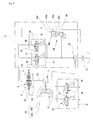
- Fig. 5 shows a block diagram of the oil-hydraulic circuit.
- the basic constitution of the oil-hydraulic circuit is similar to that of the known oil-hydraulic circuit shown in Fig. 7, except that the forward/reverse directional control valve comprises solenoid valves 35, 36.
- the forward/reverse directional control valve comprises solenoid valves 35, 36.
- the same components as in Fig. 7 will be referred to by the same numerals and their repeated explanation will be omitted.
- the oil-hydraulic control unit 31 has a relief valve 56 built therein which contains the spring bearings 56a, 56b, in addition to the solenoid valves 35, 36, and an oil passage is bored therein.
- the forward/reverse directional control valve can also comprise proportional solenoid valves 35, 36 (chain-line square B) instead of on/off type solenoid valves (chain-line square A), which enables trolling sailing.
- the solenoid valves 35, 36 are so constituted that, when they are not energized, they shift to the side so as to discontinue oil supply to the clutch 8 by return springs 37, 38. If the solenoid valves 35, 36 cannot be energized because of electric trouble such as broken electric wires, the hydraulic operating fluid supply to the clutch 8 is discharged into a drain by the return springs 37, 38, and therefore the clutch 8 is disengaged and the vessel stops.
- Each of the solenoid valves 35, 36 is provided with an emergency pin 39 which can be used to push the valve plate so as to manually supply the clutch with hydraulic operating fluid. Accordingly, the solenoid valves 35, 36 can be shifted manually to the side, so as to supply the clutch 8 with hydraulic operating fluid, against the force of the return springs 37, 38.
- the oil-hydraulic control unit 31 is positioned within a dead space of the cosmetic cover 14b, and is sealed against fluid by a waterproof cover 40, together with the solenoid valves 35, 36.
- the waterproof cover 40 is attached to the upper casing body 14a via a sealing packing (not shown) with bolts or the like.
- an electric wire 41 of the solenoid valves 35, 36 is brought into the vessel through a passage for conventional shift wire cables, and is connected to a control panel (controller) 43 on which a shift operation lever 42 (Fig. 1) is disposed.
- the electric wire 41 is brought into the vessel through a through hole 14c formed on the upper casing body 14a, and inside a flexible hose 44 which is seal-connected between the bell housing 18 and gimbal housing 9.
- This causes the inner space of the waterproof cover 40 and through hole 14c to be open to the inside of the vessel in a fluid-tight manner, thereby preventing the occurrence of harmful condensation.
- the electric wire 41 is provided with a connector 45 which separably connects a male side terminal and female side terminal.
- the male side terminal and female side terminal are disposed in a recess provided on each of the two joint surfaces of the bell housing 18 with the upper casing 14 and a male side terminal and female side terminal disposed on the bell housing 18 side and the upper casing 14 side, respectively.
- the connector 45 can be connected and accommodated inside the bell housing 18 and upper casing 14 prior to joining these components.
- the male side terminal and female side terminal of the connector 45 can be fixed in the recesses on the joint surface of the bell housing 18 and upper casing 14.
- the male side of the connector 45 is fixed on the upper casing body 14a, and the female side of the connector 45 is fixed on the bell housing 18.
- the solenoid valves 35, 36 for conducting shifting operation in the oil-hydraulic circuit which operates the hydraulic clutch 8 are disposed in the upper casing 14 of the outer drive apparatus 4, whereby adjustment of shift positions of the electric wire 41 connected to the solenoid valves 35, 36 as in known shift wire cables is unnecessary.
- the electric wires brought from the solenoid valves 35, 36 into the vessel itself does not slide by shift operation, and thus a greater allowable bending radius is ensured, which allows more freedom than in known shift wire cables. This allows more freedom in the design.
- a form comprising an hydraulic multiple-disc clutch is described, but the present invention can be also applied to forms comprising other clutches.
- a shifter 51 which operates the conventional clutch 8 shown in Fig. 7 by an electric-powered linear actuator, electric motor or other electric actuator and dispose the electric actuator in the upper housing.
- it can be also applied not only to a form comprising a friction clutch but also to that comprising a claw clutch such as a cone clutch.
Landscapes
- Engineering & Computer Science (AREA)
- Chemical & Material Sciences (AREA)
- Combustion & Propulsion (AREA)
- Mechanical Engineering (AREA)
- Ocean & Marine Engineering (AREA)
- Radar, Positioning & Navigation (AREA)
- Remote Sensing (AREA)
- Gear-Shifting Mechanisms (AREA)
- Reduction Or Emphasis Of Bandwidth Of Signals (AREA)
Abstract
Description
- The present invention relates to a shift apparatus which shifts a clutch into forward, neutral and reverse and is provided in an outer drive apparatus of an inboard-outboard drive.
- An inboard-outboard drive (a.k.a., stern drive) is a form of marine propulsion in which a main engine (a.k.a., inboard motor) is provided inside the hull and an outer drive apparatus is provided on the outside of the hull. The outer drive apparatus is a propulsion unit which integrally incorporates a reverse reduction gear, clutch mechanism, steering mechanism, propellers and is attached to a transom portion.
- In known inboard-outboard drives, a shift mechanism for switching the clutch mechanism into forward, neutral or reverse generally employs a mechanical mechanism in which a shift operation lever in the vessel and a clutch lever in the outer drive apparatus are connected by a cable such as a wire (for example,
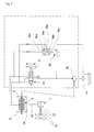
Japanese Unexamined Patent Publication No. 4-254289 - The case where an hydraulic clutch is employed in an inboard-outboard drive of this type will be described with reference to Fig. 7 as an example of the oil-hydraulic circuit:, a pressure oil discharged from a
gear pump 30 which receives a drive force from an output shaft of a main engine is transferred to aclutch 8 through a forward/reversedirectional control valve 50. The forward/reversedirectional control valve 50 is a mechanically operated valve and switched by ashifter 51. Theshifter 51 is operated by a clutch lever (not shown), and the clutch lever is connected with a shift operation lever (not shown) in the vessel by a wire cable. The oil-hydraulic circuit is provided with arelief valve 56 having a slowly engaging function to reduce the impact of rapid engagement on theclutch 8. Therelief valve 56 is provided with twospring bearings pressure regulating spring 56s and disposed serially in acylinder 56c. Therelief valve 56 is additionally provided with a pressure-regulating circuit formed by connecting throttling passages split from a forward output port and reverse output port of the forward/reversedirectional control valve 50 tooil chambers spring bearings directional control valve 50 is in the neutral position (as in Fig. 7), thespring bearings spring 56s and therelief valve 56 operates as a relief valve having a low setting pressure. When the forward/reversedirectional control valve 50 is switched to forward or reverse, the spring bearing 56a or 56b moves to compress the pressure-regulatingspring 56s with a time delay. When the setting pressure of therelief valve 56 gradually increases and the spring bearing 56a or 56b reaches a specified stroke, the maximum pressure of hydraulic operating fluid for the clutch is obtained. Thus, the pressure of the hydraulic operating fluid for the clutch is gradually increased. The drive force of the main engine is transmitted in this order: theclutch 8, theforward side gear 5 orreverse side gear 6 which is engaged with theclutch 8, abevel gear 24, adrive shaft 23, abevel gear 7, apropeller shaft 25, and apropeller 12. - As the clutch mechanism of the outer drive apparatus, friction clutches such as a multiple disc clutch (for example,
Japanese Unexamined Patent Publication No. 4-254289 Japanese Unexamined Patent Publication No. 3-10990 - Although more and more control systems for inboard-outboard drives are electronically controlled in recent years, mechanical mechanisms using a wire cable are still employed for shift mechanisms. When shift switching signals need to be electrical signals, the wire cable is operated by an actuator such as an electric motor installed in the vessel and controlled by electrical signals from a controller in the vessel.
- However, in installing the actuator, there have been problems with the numerous man hours required to couple the main engine inside the vessel and the outer drive apparatus outside the vessel, such as for example, positioning of the wire cable for the forward, neutral and reverse positions.
- Furthermore, since the wire cable has minimum bend radius and the wire cables themselves slide during switch operation, passage for the wire cable inside the outer drive apparatus is limited. Requirements for the passage in the outer drive apparatus, which has no extra space, have thus been considerably difficult to fulfil.
- Accordingly, an object of the present invention is to provide a shift apparatus of an inboard-outboard drive in which shift operation can be carried out by electrical means without using conventional cables such as wires.
- To solve the above problems, in the shift apparatus of the inboard-outboard drive according to the present invention, a solenoid valve which carries out shifting operation in an oil-hydraulic circuit which operates an hydraulic clutch is disposed within a casing of an outer drive apparatus. A connector is interposed into electric wires which electrically connect the solenoid valve and an inboard controller in a vessel. The connector is arranged on a joint portion between a bell housing and an upper casing.
- In one embodiment, an oil-hydraulic control unit which controls hydraulic operating fluid for the clutch is disposed within the outer drive apparatus, and the solenoid valve is attached to the oil-hydraulic control unit.
- Moreover, in the shift apparatus of the inboard-outboard drive according to the present invention, an electric actuator which shifts the clutch is disposed within the casing of the outer drive apparatus. The connector is interposed into electric wires which electrically connect the electric actuator and the inboard controller, and the connector is arranged on the joint portion between a bell housing and an upper casing.
- In one embodiment, a waterproof cover which hermetically seals the solenoid valve is further attached.
- According to the present invention, switching of the clutch is carried out by the solenoid valve or electric actuator. Therefore, mechanical shift wires for switching the clutch as in known shift apparatuses are unnecessary. The shift apparatus of the present invention can be thus installed without positioning of the cable which has been conventionally carried out. Moreover, choosing passages for the cables inside the outer drive apparatus is facilitated.
-
- Fig. 1 is a partial sectional view of the shift apparatus of the inboard-outboard drive according to the present invention.
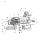
- Fig. 2 is a longitudinal sectional view showing a relevant part of the outer drive apparatus of the inboard-outboard drive in Fig. 1, and is a sectional view taken along the line II-II in Fig. 4.
- Fig. 3 is a longitudinal sectional view showing relevant parts of the outer drive apparatus of the inboard-outboard drive in Fig. 1, and is a sectional view taken along the line III-III in Fig. 4.
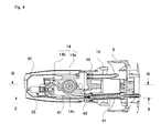
- Fig. 4 is a horizontal sectional view showing relevant parts of the outer drive apparatus of the inboard-outboard drive in Fig. 1, and is a sectional view taken along the line IV-IV in Fig. 3.
- Fig. 5 is a diagram of the oil-hydraulic circuit of the outer drive apparatus in Fig. 1.
- Fig. 6 is an expanded longitudinal sectional view of a connector of an electric wire.
- Fig. 7 is a diagram of an oil-hydraulic circuit of a known outer drive apparatus.
- Regarding the shift apparatus of the inboard-outboard drive according to the present invention, its suitable embodiments will be described with reference to Figs. 1 to 6.
- As shown in Fig. 1, the inboard-
outboard drive 1 is provided with amain engine 2 inside ahull 3 and anouter drive apparatus 4 outside thehull 3. Theouter drive apparatus 4 integrally incorporates a reverse reduction gear comprising aforward gear 5, areverse gear 6, abevel gear 7 and others, aclutch 8, a steering mechanism (9, 10, 11) (refer to Fig. 3) and a pair of front andrear propellers 12 and other components. Theouter drive apparatus 4 is attached to atransom portion 13. - The
outer drive apparatus 4 is provided with a casing comprising anupper casing 14 and alower casing 15. In the example illustrated, theupper casing 14 further has anupper casing body 14a accommodating theforward gear 5,gear 6,clutch 8 and other components, and acosmetic cover 14b which is attached to theupper casing body 14a. Theouter drive apparatus 4 comprises agimbal housing 9 fixed on thetransom portion 13, agimbal ring 10 supported bypivot shafts gimbal housing 9, and abell housing 18 supported on the left and right side of thegimbal ring 10 via a pivot shaft (not shown). Theupper casing 14 is fixed on thebell housing 18, and is thus supported freely movably vertically and horizontally. Vertical tilting of theouter drive apparatus 4 is carried out by an hydraulic cylinder 19 (Fig. 1), while horizontal tilting, i.e., steering, is carried out by a steering lever 11 (Fig. 3). - As shown in Fig. 3, an
output shaft 20 powered by themain engine 2 is connected to aclutch shaft 22 disposed within theupper casing body 14a of theouter drive apparatus 4 via auniversal joint 21. Theclutch shaft 22 is provided with theforward gear 5 andreverse gear 6 which are rotatably fitted thereon, and a hydraulic multiple-disc clutch 8 which connects either of theforward gear 5 orreverse gear 6 to theclutch shaft 22. - The
forward gear 5 andreverse gear 6 engage thebevel gear 24 fixed on the upper end of thedrive shaft 23 extending in the vertical direction. The lower end of thedrive shaft 23 is connected to apropeller shaft 25 consisting of a contra-rotating shaft comprising asolid shaft 25a andhollow shaft 25b via a plurality ofbevel gears 7. Thesolid shaft 25a andhollow shaft 25b are always driven in directions opposite to each other to rotate two front andrear propellers 12. - An hydraulic pump 30 (Fig. 3) is disposed on the aft side edge of the
clutch shaft 22. Thehydraulic pump 30 in the example illustrated is a gear pump comprising a pair of gears. One of the gears constituting the gear pump, agear 30a, is engaged with the edge of theclutch shaft 22 and rotates with theclutch shaft 22, whereby the oil is pumped up from an oil sump formed in the casing so that hydraulic operating fluid is supplied to theclutch 8. A trochoidal pump can be also used as a hydraulic pump. - An oil-
hydraulic control unit 31, integrating thehydraulic pump 30 and a hydraulic control circuit which controls hydraulic operating fluid for the clutch, is attached to the aft side of theupper casing body 14a. - Fig. 5 shows a block diagram of the oil-hydraulic circuit. The basic constitution of the oil-hydraulic circuit is similar to that of the known oil-hydraulic circuit shown in Fig. 7, except that the forward/reverse directional control valve comprises
solenoid valves - The oil-
hydraulic control unit 31 has arelief valve 56 built therein which contains thespring bearings solenoid valves proportional solenoid valves 35, 36 (chain-line square B) instead of on/off type solenoid valves (chain-line square A), which enables trolling sailing. - The
solenoid valves solenoid valves clutch 8 is discharged into a drain by the return springs 37, 38, and therefore theclutch 8 is disengaged and the vessel stops. Each of thesolenoid valves emergency pin 39 which can be used to push the valve plate so as to manually supply the clutch with hydraulic operating fluid. Accordingly, thesolenoid valves clutch 8 with hydraulic operating fluid, against the force of the return springs 37, 38. - The oil-
hydraulic control unit 31 is positioned within a dead space of thecosmetic cover 14b, and is sealed against fluid by awaterproof cover 40, together with thesolenoid valves waterproof cover 40 is attached to theupper casing body 14a via a sealing packing (not shown) with bolts or the like. As shown in Figs. 2 and 4, anelectric wire 41 of thesolenoid valves electric wire 41 is brought into the vessel through a throughhole 14c formed on theupper casing body 14a, and inside aflexible hose 44 which is seal-connected between thebell housing 18 andgimbal housing 9. This causes the inner space of thewaterproof cover 40 and throughhole 14c to be open to the inside of the vessel in a fluid-tight manner, thereby preventing the occurrence of harmful condensation. - As shown in Fig. 4, the
electric wire 41 is provided with aconnector 45 which separably connects a male side terminal and female side terminal. The male side terminal and female side terminal are disposed in a recess provided on each of the two joint surfaces of thebell housing 18 with theupper casing 14 and a male side terminal and female side terminal disposed on thebell housing 18 side and theupper casing 14 side, respectively. Theconnector 45 can be connected and accommodated inside thebell housing 18 andupper casing 14 prior to joining these components. - As shown in Fig. 6, the male side terminal and female side terminal of the
connector 45 can be fixed in the recesses on the joint surface of thebell housing 18 andupper casing 14. In the example illustrated, the male side of theconnector 45 is fixed on theupper casing body 14a, and the female side of theconnector 45 is fixed on thebell housing 18. By placing theconnector 45 in this position, positioning theupper casing 14 and thebell housing 18 during assembly and attaching of the former to the latter, theconnector 45 is connected, thereby facilitating the installing operation. - As can be seen from the above description, according to the shift apparatus of the inboard-outboard drive having the above constitution, the
solenoid valves hydraulic clutch 8 are disposed in theupper casing 14 of theouter drive apparatus 4, whereby adjustment of shift positions of theelectric wire 41 connected to thesolenoid valves solenoid valves - In the above embodiment, a form comprising an hydraulic multiple-disc clutch is described, but the present invention can be also applied to forms comprising other clutches. For example, it is also possible to operate a
shifter 51 which operates theconventional clutch 8 shown in Fig. 7 by an electric-powered linear actuator, electric motor or other electric actuator and dispose the electric actuator in the upper housing. Moreover, it can be also applied not only to a form comprising a friction clutch but also to that comprising a claw clutch such as a cone clutch.
Claims (5)
- A shift apparatus for an inboard-outboard drive having an outer drive apparatus (4), comprising:an hydraulic clutch (8) disposed within a casing (14) of the outer drive apparatus;an oil-hydraulic circuit for operating the hydraulic clutch (8) ;at least one solenoid valve (35, 36) for performing a switching operation of the oil-hydraulic circuit ;electric wires (41) which electrically connect the solenoid valve (35, 36) and an inboard controller ; anda connector interposed between electric wires, and arranged on a joint portion between a bell housing (18) and an upper casing (14).
- The shift apparatus according to claim 1, further comprising an oil-hydraulic control unit (31), for controlling hydraulic operating fluid for the clutch, is disposed in the outer drive apparatus, wherein the solenoid valve (35, 36) is attached to the oil-hydraulic control unit (31).
- The shift apparatus according to claim 1, further comprising a waterproof cover (40) which hermetically seals the solenoid valve (35, 36).
- A shift apparatus for an inboard-outboard drive having an outer drive apparatus (4) comprising:a clutch (8) disposed in a casing of the outer drive apparatus (4) ;at least one electric actuator (35, 36) for shifting the clutch (8) ;electric wires (41) which electrically connect the electric actuator (35, 36) and an inboard controller ; anda connector (45) interposed between the electric wires (41) and arranged on a joint portion between a bell housing (18) and an upper casing (14).
- The shift apparatus according to claim 4, further comprising a waterproof cover (40) which hermetically seals the solenoid valve (35, 36).
Applications Claiming Priority (1)
| Application Number | Priority Date | Filing Date | Title |
|---|---|---|---|
| JP2006166429A JP2007331603A (en) | 2006-06-15 | 2006-06-15 | Shift device for inboard and outboard engine |
Publications (3)
| Publication Number | Publication Date |
|---|---|
| EP1867566A2 true EP1867566A2 (en) | 2007-12-19 |
| EP1867566A3 EP1867566A3 (en) | 2011-08-10 |
| EP1867566B1 EP1867566B1 (en) | 2013-03-27 |
Family
ID=38515490
Family Applications (1)
| Application Number | Title | Priority Date | Filing Date |
|---|---|---|---|
| EP07290720A Not-in-force EP1867566B1 (en) | 2006-06-15 | 2007-06-11 | Shift apparatus for inboard-outboard drive |
Country Status (4)
| Country | Link |
|---|---|
| US (1) | US8020684B2 (en) |
| EP (1) | EP1867566B1 (en) |
| JP (1) | JP2007331603A (en) |
| NO (1) | NO337804B1 (en) |
Cited By (2)
| Publication number | Priority date | Publication date | Assignee | Title |
|---|---|---|---|---|
| EP2281744A1 (en) * | 2009-08-07 | 2011-02-09 | Yanmar Co., Ltd. | Outdrive unit for boats |
| EP2899114A4 (en) * | 2012-09-21 | 2016-08-03 | Yanmar Co Ltd | Marine gear device |
Families Citing this family (1)
| Publication number | Priority date | Publication date | Assignee | Title |
|---|---|---|---|---|
| US10118683B1 (en) | 2017-08-21 | 2018-11-06 | Brunswick Corporation | Outboard motors having flexible connector assembly for shift actuation |
Citations (1)
| Publication number | Priority date | Publication date | Assignee | Title |
|---|---|---|---|---|
| JPH04254289A (en) | 1991-02-06 | 1992-09-09 | Yamaha Motor Co Ltd | Shift device for inboard/outboard engine |
Family Cites Families (21)
| Publication number | Priority date | Publication date | Assignee | Title |
|---|---|---|---|---|
| US3919510A (en) * | 1973-05-29 | 1975-11-11 | Brunswick Corp | Electrically controlled shift mechanism for marine propulsion units |
| GB1474045A (en) | 1974-12-06 | 1977-05-18 | Buddrus C | Marine propulsion and guidance system |
| US4070926A (en) * | 1975-12-22 | 1978-01-31 | Twin Disc, Incorporated | Swing control for crane |
| US4186829A (en) * | 1977-11-14 | 1980-02-05 | Twin Disc, Incorporated | Modulatable power transmission clutch |
| JPS5534044U (en) * | 1978-08-25 | 1980-03-05 | ||
| GB2079705A (en) | 1980-07-15 | 1982-01-27 | Pumphrey Gordon Lloyd | Hydraulic power unit for an outboard motor |
| US4659315A (en) * | 1985-05-06 | 1987-04-21 | Outboard Marine Corporation | Hydraulic system for marine propulsion devices |
| US4871048A (en) * | 1987-09-21 | 1989-10-03 | Dresser Industries, Inc. | Control system for vehicle transmissions |
| US4836809A (en) * | 1988-03-11 | 1989-06-06 | Twin Disc, Incorporated | Control means for marine propulsion system |
| US5033983A (en) * | 1989-05-12 | 1991-07-23 | Outboard Marine Corporation | Marine propulsion device shift linkage |
| ZA918426B (en) | 1990-10-31 | 1992-12-30 | Akzo Nv | Chicken anemia virus vaccine and diagnostic |
| US5327793A (en) * | 1991-02-05 | 1994-07-12 | Yamaha Hatsudoki Kabushiki Kaisha | Thrust bearings and bevel gears arrangement of marine propulsion unit |
| JP3109606B2 (en) * | 1991-06-10 | 2000-11-20 | ヤマハ発動機株式会社 | Mounting structure for side covers of inboard and outboard motors |
| US5492493A (en) * | 1994-07-07 | 1996-02-20 | Sanshin Kogyo Kabushiki Kaisha | Remote control device for marine propulsion unit |
| US5476400A (en) * | 1994-10-12 | 1995-12-19 | Theophanides; Andy E. | Hydraulic power system for a boat |
| US5711742A (en) * | 1995-06-23 | 1998-01-27 | Brunswick Corporation | Multi-speed marine propulsion system with automatic shifting mechanism |
| JPH09315389A (en) * | 1996-05-30 | 1997-12-09 | Aisin Seiki Co Ltd | Power transmission device for inboard and outboard motors |
| WO1998029302A1 (en) * | 1996-12-30 | 1998-07-09 | Ab Volvo Penta | Valve assembly and a method of operating a power transmission |
| FR2782354B1 (en) * | 1998-07-28 | 2001-03-30 | Valeo Equip Electr Moteur | FRICTION CLUTCH CARRYING THE ROTOR OF AN ELECTRIC MACHINE, PARTICULARLY FOR A MOTOR VEHICLE |
| US6350165B1 (en) * | 2000-06-21 | 2002-02-26 | Bombardier Motor Corporation Of America | Marine stern drive two-speed transmission |
| JP4254289B2 (en) | 2003-03-20 | 2009-04-15 | 東レ株式会社 | Laminated polypropylene film and fusing sealed package comprising the same |
-
2006
- 2006-06-15 JP JP2006166429A patent/JP2007331603A/en active Pending
-
2007
- 2007-06-05 US US11/806,990 patent/US8020684B2/en not_active Expired - Fee Related
- 2007-06-11 EP EP07290720A patent/EP1867566B1/en not_active Not-in-force
- 2007-06-15 NO NO20073061A patent/NO337804B1/en unknown
Patent Citations (1)
| Publication number | Priority date | Publication date | Assignee | Title |
|---|---|---|---|---|
| JPH04254289A (en) | 1991-02-06 | 1992-09-09 | Yamaha Motor Co Ltd | Shift device for inboard/outboard engine |
Cited By (3)
| Publication number | Priority date | Publication date | Assignee | Title |
|---|---|---|---|---|
| EP2281744A1 (en) * | 2009-08-07 | 2011-02-09 | Yanmar Co., Ltd. | Outdrive unit for boats |
| US8277268B2 (en) | 2009-08-07 | 2012-10-02 | Yanmar Co., Ltd. | Outdrive unit for boats |
| EP2899114A4 (en) * | 2012-09-21 | 2016-08-03 | Yanmar Co Ltd | Marine gear device |
Also Published As
| Publication number | Publication date |
|---|---|
| JP2007331603A (en) | 2007-12-27 |
| NO337804B1 (en) | 2016-06-27 |
| US20070289838A1 (en) | 2007-12-20 |
| US8020684B2 (en) | 2011-09-20 |
| EP1867566B1 (en) | 2013-03-27 |
| NO20073061L (en) | 2007-12-17 |
| EP1867566A3 (en) | 2011-08-10 |
Similar Documents
| Publication | Publication Date | Title |
|---|---|---|
| EP1352178B1 (en) | Modulatable power transmission clutch and a marine transmission | |
| US6755703B1 (en) | Hydraulically assisted gear shift mechanism for a marine propulsion device | |
| US10215278B1 (en) | Shift system for a marine drive | |
| AU2002236785A1 (en) | Modulatable power transmission clutch and a marine transmission | |
| US7291048B1 (en) | Actuator device for a marine propulsion transmission | |
| JP2007530874A (en) | Opposing pump / motor | |
| US8047152B2 (en) | Hinge joint for cylinder actuators of watercraft trim tabs, trim tab and trim tab control system | |
| EP1499527B1 (en) | Modulatable power transmission clutch and a marine transmission | |
| US12241486B2 (en) | Hydraulic transmission unit, particularly for deep-sea use | |
| US6296535B1 (en) | Tilt-trim subsystem for boats using a stern drive system | |
| US9896177B1 (en) | Shift system for a marine drive | |
| EP1867566B1 (en) | Shift apparatus for inboard-outboard drive | |
| US5231890A (en) | Shifting system for outboard drive unit | |
| US20020034899A1 (en) | Parallel-operated hydraulic motor type stern propulsion apparatus for boats and hydraulic system for controlling the same | |
| US20150004855A1 (en) | Gear case assembly for an outboard engine | |
| EP3760533A1 (en) | Outboard motor | |
| JPH03273995A (en) | Assistor mechanism of ship propulsion machine | |
| JP2015199373A (en) | Marine gear device and ship equipped with the same | |
| KR101720713B1 (en) | Hybrid steering apparutus for a boat with outboard engine | |
| EP1681235A1 (en) | Marine reversing gear assembly provided with locking device | |
| US4449469A (en) | Mechanical clutch/decoupler for hydraulic pumps | |
| JP2001001992A (en) | Shift switching method of in-board and outboard motor | |
| EP2492187B1 (en) | Power transmission device of outboard motor | |
| JPH11182582A (en) | Shifting method of inboard/outboard motor | |
| JP2015199372A (en) | Marine gear device and vessel equipped with the same |
Legal Events
| Date | Code | Title | Description |
|---|---|---|---|
| PUAI | Public reference made under article 153(3) epc to a published international application that has entered the european phase |
Free format text: ORIGINAL CODE: 0009012 |
|
| AK | Designated contracting states |
Kind code of ref document: A2 Designated state(s): AT BE BG CH CY CZ DE DK EE ES FI FR GB GR HU IE IS IT LI LT LU LV MC MT NL PL PT RO SE SI SK TR |
|
| AX | Request for extension of the european patent |
Extension state: AL BA HR MK YU |
|
| RAP1 | Party data changed (applicant data changed or rights of an application transferred) |
Owner name: YANMAR CO., LTD. |
|
| PUAL | Search report despatched |
Free format text: ORIGINAL CODE: 0009013 |
|
| AK | Designated contracting states |
Kind code of ref document: A3 Designated state(s): AT BE BG CH CY CZ DE DK EE ES FI FR GB GR HU IE IS IT LI LT LU LV MC MT NL PL PT RO SE SI SK TR |
|
| AX | Request for extension of the european patent |
Extension state: AL BA HR MK RS |
|
| RIC1 | Information provided on ipc code assigned before grant |
Ipc: B63H 23/30 20060101ALI20110701BHEP Ipc: B63H 23/24 20060101ALI20110701BHEP Ipc: B63H 20/20 20060101ALI20110701BHEP Ipc: B63H 20/16 20060101ALI20110701BHEP Ipc: B63H 23/26 20060101AFI20110701BHEP |
|
| 17P | Request for examination filed |
Effective date: 20120210 |
|
| AKX | Designation fees paid |
Designated state(s): ES FI FR GB IT SE |
|
| REG | Reference to a national code |
Ref country code: DE Ref legal event code: R108 Effective date: 20120419 |
|
| GRAP | Despatch of communication of intention to grant a patent |
Free format text: ORIGINAL CODE: EPIDOSNIGR1 |
|
| RIC1 | Information provided on ipc code assigned before grant |
Ipc: B63H 23/30 20060101ALI20121019BHEP Ipc: B63H 23/24 20060101ALI20121019BHEP Ipc: B63H 20/16 20060101ALI20121019BHEP Ipc: B63H 23/26 20060101AFI20121019BHEP Ipc: B63H 20/20 20060101ALI20121019BHEP |
|
| GRAS | Grant fee paid |
Free format text: ORIGINAL CODE: EPIDOSNIGR3 |
|
| GRAA | (expected) grant |
Free format text: ORIGINAL CODE: 0009210 |
|
| AK | Designated contracting states |
Kind code of ref document: B1 Designated state(s): ES FI FR GB IT SE |
|
| REG | Reference to a national code |
Ref country code: GB Ref legal event code: FG4D |
|
| REG | Reference to a national code |
Ref country code: SE Ref legal event code: TRGR |
|
| PG25 | Lapsed in a contracting state [announced via postgrant information from national office to epo] |
Ref country code: FI Free format text: LAPSE BECAUSE OF FAILURE TO SUBMIT A TRANSLATION OF THE DESCRIPTION OR TO PAY THE FEE WITHIN THE PRESCRIBED TIME-LIMIT Effective date: 20130327 |
|
| PG25 | Lapsed in a contracting state [announced via postgrant information from national office to epo] |
Ref country code: ES Free format text: LAPSE BECAUSE OF FAILURE TO SUBMIT A TRANSLATION OF THE DESCRIPTION OR TO PAY THE FEE WITHIN THE PRESCRIBED TIME-LIMIT Effective date: 20130708 |
|
| PLBE | No opposition filed within time limit |
Free format text: ORIGINAL CODE: 0009261 |
|
| STAA | Information on the status of an ep patent application or granted ep patent |
Free format text: STATUS: NO OPPOSITION FILED WITHIN TIME LIMIT |
|
| 26N | No opposition filed |
Effective date: 20140103 |
|
| REG | Reference to a national code |
Ref country code: FR Ref legal event code: ST Effective date: 20140228 |
|
| PG25 | Lapsed in a contracting state [announced via postgrant information from national office to epo] |
Ref country code: FR Free format text: LAPSE BECAUSE OF NON-PAYMENT OF DUE FEES Effective date: 20130701 |
|
| PGFP | Annual fee paid to national office [announced via postgrant information from national office to epo] |
Ref country code: GB Payment date: 20240619 Year of fee payment: 18 |
|
| PGFP | Annual fee paid to national office [announced via postgrant information from national office to epo] |
Ref country code: SE Payment date: 20240619 Year of fee payment: 18 |
|
| PGFP | Annual fee paid to national office [announced via postgrant information from national office to epo] |
Ref country code: IT Payment date: 20240625 Year of fee payment: 18 |
|
| REG | Reference to a national code |
Ref country code: SE Ref legal event code: EUG |
|
| GBPC | Gb: european patent ceased through non-payment of renewal fee |
Effective date: 20250611 |
|
| PG25 | Lapsed in a contracting state [announced via postgrant information from national office to epo] |
Ref country code: GB Free format text: LAPSE BECAUSE OF NON-PAYMENT OF DUE FEES Effective date: 20250611 |
|
| PG25 | Lapsed in a contracting state [announced via postgrant information from national office to epo] |
Ref country code: IT Free format text: LAPSE BECAUSE OF NON-PAYMENT OF DUE FEES Effective date: 20250611 |