EP1352178B1 - Modulatable power transmission clutch and a marine transmission - Google Patents
Modulatable power transmission clutch and a marine transmission Download PDFInfo
- Publication number
- EP1352178B1 EP1352178B1 EP02703149A EP02703149A EP1352178B1 EP 1352178 B1 EP1352178 B1 EP 1352178B1 EP 02703149 A EP02703149 A EP 02703149A EP 02703149 A EP02703149 A EP 02703149A EP 1352178 B1 EP1352178 B1 EP 1352178B1
- Authority
- EP
- European Patent Office
- Prior art keywords
- clutch
- piston
- fluid
- modulatable
- power transmission
- Prior art date
- Legal status (The legal status is an assumption and is not a legal conclusion. Google has not performed a legal analysis and makes no representation as to the accuracy of the status listed.)
- Expired - Lifetime
Links
Images


Classifications
-
- B—PERFORMING OPERATIONS; TRANSPORTING
- B63—SHIPS OR OTHER WATERBORNE VESSELS; RELATED EQUIPMENT
- B63H—MARINE PROPULSION OR STEERING
- B63H23/00—Transmitting power from propulsion power plant to propulsive elements
- B63H23/30—Transmitting power from propulsion power plant to propulsive elements characterised by use of clutches
-
- F—MECHANICAL ENGINEERING; LIGHTING; HEATING; WEAPONS; BLASTING
- F16—ENGINEERING ELEMENTS AND UNITS; GENERAL MEASURES FOR PRODUCING AND MAINTAINING EFFECTIVE FUNCTIONING OF MACHINES OR INSTALLATIONS; THERMAL INSULATION IN GENERAL
- F16D—COUPLINGS FOR TRANSMITTING ROTATION; CLUTCHES; BRAKES
- F16D25/00—Fluid-actuated clutches
- F16D25/06—Fluid-actuated clutches in which the fluid actuates a piston incorporated in, i.e. rotating with the clutch
- F16D25/062—Fluid-actuated clutches in which the fluid actuates a piston incorporated in, i.e. rotating with the clutch the clutch having friction surfaces
- F16D25/063—Fluid-actuated clutches in which the fluid actuates a piston incorporated in, i.e. rotating with the clutch the clutch having friction surfaces with clutch members exclusively moving axially
- F16D25/0635—Fluid-actuated clutches in which the fluid actuates a piston incorporated in, i.e. rotating with the clutch the clutch having friction surfaces with clutch members exclusively moving axially with flat friction surfaces, e.g. discs
- F16D25/0638—Fluid-actuated clutches in which the fluid actuates a piston incorporated in, i.e. rotating with the clutch the clutch having friction surfaces with clutch members exclusively moving axially with flat friction surfaces, e.g. discs with more than two discs, e.g. multiple lamellae
-
- F—MECHANICAL ENGINEERING; LIGHTING; HEATING; WEAPONS; BLASTING
- F16—ENGINEERING ELEMENTS AND UNITS; GENERAL MEASURES FOR PRODUCING AND MAINTAINING EFFECTIVE FUNCTIONING OF MACHINES OR INSTALLATIONS; THERMAL INSULATION IN GENERAL
- F16D—COUPLINGS FOR TRANSMITTING ROTATION; CLUTCHES; BRAKES
- F16D25/00—Fluid-actuated clutches
- F16D25/12—Details not specific to one of the before-mentioned types
- F16D25/14—Fluid pressure control
-
- F—MECHANICAL ENGINEERING; LIGHTING; HEATING; WEAPONS; BLASTING
- F16—ENGINEERING ELEMENTS AND UNITS; GENERAL MEASURES FOR PRODUCING AND MAINTAINING EFFECTIVE FUNCTIONING OF MACHINES OR INSTALLATIONS; THERMAL INSULATION IN GENERAL
- F16D—COUPLINGS FOR TRANSMITTING ROTATION; CLUTCHES; BRAKES
- F16D48/00—External control of clutches
- F16D48/02—Control by fluid pressure
- F16D2048/0209—Control by fluid pressure characterised by fluid valves having control pistons, e.g. spools
Definitions
- This invention relates generally to modulatable power transmission clutches and, in particular, to those wherein a fluid-applied spring release piston operates on clutch plates which are disposed between a rotatable driving member and a rotatable driven member to effect clutch modulation.
- U.S. Patent No. 4,459,873, issued July 17, 1984 to Black shows a marine propulsion system and discusses a brake which is engaged to anchor a portion of the planetary gear system to drive the propeller in a forward direction, and the brake is disengaged when the torque converter is driving the propeller shaft in the reverse direction.
- This patent discusses prior art transmissions, which were not always satisfactory because of flutter failure of the forward drive clutch, when it was required to operate in the reverse direction for reversing the direction of the boat.
- U.S. Patent No. 4,836,809 issued June 6, 1989 to Pelligrino , discloses a marine vessel propulsion system having forward and reverse clutches in which each clutch can be fully engaged, Fully disengaged, and modulated.
- the present invention Is directed to a modulatable power transmission clutch as defined in the preamble of claim 1, a marine transmission for variable speed control of a boat according to the preamble of claim 3 and a power transmission according to the preamble of claim 4, cf. US 4,186,829 .
- US 4,186,829 describes a modulatable power transmission clutch including interleaved clutch plates.
- the clutch plates are compressed by a piston having a small and a large piston area. Fluid connection to the small area is open and modulatable, while fluid connection to the large piston area is openable and closable by a valve if the pressure in the fluid exceeds a predetermined amount.
- the valve is complicated in design and requires time consuming mounting, and is arranged in radial direction with respect to the shaft, thereby being subjected to gravity forces.
- US 4,969,546 describes a fluid operated clutch having a valve arranged axially slidably in an axially extending hole within the shaft
- the clutch includes a piston having only one operative piston area; the valve is adapted to limit the pressure acting on the piston. For that reason both sides of the valve are subjected to fluid pressure.
- the present invention provides a modulatable power transmission clutch and also a marine transmission system for variable speed control having dual area clutch pistons. Clutch capacity is varied by separate fluid areas of the clutch, one area being smaller than the other.
- the marine transmission clutch is modulated by means of the small area of the piston utilizing a selectively operable control resulting in variable propeller speed. Pressure fluid is supplied to the small area by controlling a proportional valve. Modulation of the clutch offers enhanced docking control and vessel positioning. At a predetermined pressure level at the source area of the piston, a spring biased trigger valve allows the flow of pressure fluid to the large area of the piston whereby the clutch can reach full clutch capacity.
- the system offers seamless transition from modulating operation of the clutch where engine speed can be increased slightly to full engagement of the clutch.
- the dual area clutch provided by the present invention provides smooth transition from the initial docking mode and provides for precise and rapid back and forth changes in speed for maneuvering in the docking procedure.
- the valve of the present invention is located in the central power transmission shaft that extends through the clutch, is much less complicated than the valves of the prior art, and is not affected by centrifugal pressure.
- the present invention relates to a forward clutch F of the type having interleaved friction plates some of which are splined respectively to a hollow cylinder housing 10 that is fixed to a power input shaft 11 on which it is mounted for rotation therewith and driven by engine E ( Fig. 2 ) through input coupling G splined to shaft 11.
- the other interleaved plates are splined to the output gear 12 as is conventional.
- a spring 14 mounted around shaft 11 and at one end bears against an axially fixed snap ring 15. The other end of the spring acts against the clutch piston 17 that is slidable in the chamber 18, to urge the piston to a clutch disengaged position.
- annular piston 17 has a smaller area 20, which defines with the housing 10 and small clutch actuating chamber 21.
- the piston 17 also has a larger area 24, which with the housing defines a large clutch actuating chamber 25.
- a fluid passage 30 is rifle drilled in shaft 11 for conducting pressure fluid from a proportional valve 70, and through a cross port 31 to the small piston area 20.
- a spring loaded trigger valve 35 shown on an enlarged scale in Figs. 4 and 5 , is located in passage 30 and the head 35 of the valve acts under the action of the spring 36 and against valve seat 37 formed in the passage 30.
- Fluid passage 40 places fluid passage 30 in communication with the large area of the chamber 25 when pressure fluid in passage 30 is great enough to compress spring 36.
- the forward clutch F and reverse clutch R are in constant mesh with one another through their annular external gears 50 and 51 formed around their housing.
- Gear 60 is fixed to the propeller shaft 61, which is suitably journaled in the gear transmission case 64.
- Shaft 62 of the reverse clutch R, shaft 11 of the forward shaft and the propeller shaft 61 are all suitably journaled in the gear casing 64 on conventional antifriction tapered roller bearings as shown.
- the forward clutch F shown and described in Fig. 1 is the same as the reverse clutch R and further description of the reverse clutch is deemed to be neither necessary nor desirable.
- the gears 12, 52 and 60 are in constant mesh.
- the reverse clutch R is used to reverse output direction.
- a control lever L is utilized, through an electronic controller EC, to select operation of the either the forward or the reverse clutch.
- the lever L When the lever L is moved to the right, it causes actuation of the forward clutch. Conversely, when the lever L is moved to the left, it causes actuation of the reverse clutch.
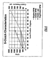
- the lever has a troll position in either forward or reverse. When the lever is moved from neutral to the troll position, the clutch operates in a troll mode. Then further movement of the lever acts to cause increase in engine speed. As shown in Fig. 6 , when the lever reaches the 40° mark, continued movement of the lever increases the engine/clutch rpm as shown.
- the proportional valve 70 is provided for the forward clutch F and a proportional valve 72 is provided for the reverse clutch R. Proportional valves 70 and 72 are similar and operate to draw pressure fluid from the source 73 and direct it to either clutch F or clutch R, respectively. Pressure fluid is also directed to a main regulator 75 ( Fig. 1 ) and lubrication passage 76 for lubricating the drive plates and bearings of the clutches via the rifle drilling 77 in the shaft and in the known manner.
- the electronic control (EC) is microprocessor-based and sends a pulse width modulated (PWM) signal to control the proportional valves 70 and 72 for each clutch.
- PWM pulse width modulated
- the level of the PWM signal sent to the valves is directly related to the position of lever L.
- the electronic control (EC) is programmable to allow the engine speed to match the propeller horsepower selected for clutch synchronization.
- the present invention provides for a marine Transmission system for variable speed control comprising an electronic control system and dual area clutch pistons. Clutch capacity is varied by separate fluid areas to the clutch, one area being smaller than the other.
- the marine transmission clutch is modulated via the small area of the piston utilizing a selectively operable control allowing variable propeller speed. Fluid is supplied to the small area by controlling a proportional valve via the control. Modulation offers enhanced docking control and vessel positioning. At a predetermined level, a spring biased trigger valve controls the fluid to the large area of the piston to reach full clutch capacity.
- the initial actuation or modulation of the clutch is utilized, for example, for marine boats for docking and vessel positioning.
- the fluid pump P ( Fig. 1 ) which supplies fluid to the proportional valves 70 or 72 provides fluid pressure.
- the lever L in the quadrant shown in Fig. 1 which is movable from a neutral position to a detent position and then to forward position, actuates the valves.
- the quadrant can be swung in the opposite direction for reverse of the transmission when fluid is directed to the other proportional valve 72 for reverse operation of the Transmission.
- pressure fluid is first admitted to the small area 20 behind the piston 17 and after it reaches a certain pressure, the piston is urged to open against the pressure of its spring 14 and permit pressure fluid to flow to the large area behind the piston.
- the arrangement provides for a variable speed control and clutch capacity is varied by separate fluid areas of the clutch, one area being smaller than the other area.
- the transmission clutches are modulated via the small area of the piston utilizing a selectively operable control allowing variable output speed.
- Modulation of the clutch offers docking control and vessel positioning. Then at a predetermined pressure level, the spring biased trigger valve controls the flow of fluid to the large area of the piston to thereby cause it to reach full clutch capacity. This system provides seamless transition from modulation to full engagement. During modulation, engine speed can be increased slightly. After modulation the engine throttle is controlled.
- the present trigger valve in its operation is much simpler than the prior art triggering valve. This provides for immediate response during modulation and the engine speed can be increased slightly and accurately in either direction to provide precise and rapid back and forth changes in speed for maneuvering, for example, of the boat during the docking procedure.
Description
- This invention relates generally to modulatable power transmission clutches and, in particular, to those wherein a fluid-applied spring release piston operates on clutch plates which are disposed between a rotatable driving member and a rotatable driven member to effect clutch modulation.
- Each of the following U.S. patents has been assigned to an assignee common with the present application.
-
U.S. Patent No. 4,451,238, issued May 29, 1984 to Arnold , discloses a multi-clutch transmission with forward and reverse shafts and gear trains between these shafts, and discusses the damaging shocks to the propulsion system which sometimes occur during maneuvering operations. -
U.S. Patent No. 4,459,873, issued July 17, 1984 to Black , shows a marine propulsion system and discusses a brake which is engaged to anchor a portion of the planetary gear system to drive the propeller in a forward direction, and the brake is disengaged when the torque converter is driving the propeller shaft in the reverse direction. This patent discusses prior art transmissions, which were not always satisfactory because of flutter failure of the forward drive clutch, when it was required to operate in the reverse direction for reversing the direction of the boat. -
U.S. Patent No. 4,836,809, issued June 6, 1989 to Pelligrino , discloses a marine vessel propulsion system having forward and reverse clutches in which each clutch can be fully engaged, Fully disengaged, and modulated. - The present invention Is directed to a modulatable power transmission clutch as defined in the preamble of claim 1, a marine transmission for variable speed control of a boat according to the preamble of claim 3 and a power transmission according to the preamble of claim 4, cf.
US 4,186,829 . -
US 4,186,829 describes a modulatable power transmission clutch including interleaved clutch plates. The clutch plates are compressed by a piston having a small and a large piston area. Fluid connection to the small area is open and modulatable, while fluid connection to the large piston area is openable and closable by a valve if the pressure in the fluid exceeds a predetermined amount. The valve is complicated in design and requires time consuming mounting, and is arranged in radial direction with respect to the shaft, thereby being subjected to gravity forces. -
US 4,969,546 describes a fluid operated clutch having a valve arranged axially slidably in an axially extending hole within the shaft The clutch includes a piston having only one operative piston area; the valve is adapted to limit the pressure acting on the piston. For that reason both sides of the valve are subjected to fluid pressure. - The present invention provides a modulatable power transmission clutch and also a marine transmission system for variable speed control having dual area clutch pistons. Clutch capacity is varied by separate fluid areas of the clutch, one area being smaller than the other. The marine transmission clutch is modulated by means of the small area of the piston utilizing a selectively operable control resulting in variable propeller speed. Pressure fluid is supplied to the small area by controlling a proportional valve. Modulation of the clutch offers enhanced docking control and vessel positioning. At a predetermined pressure level at the source area of the piston, a spring biased trigger valve allows the flow of pressure fluid to the large area of the piston whereby the clutch can reach full clutch capacity. The system offers seamless transition from modulating operation of the clutch where engine speed can be increased slightly to full engagement of the clutch.
- The dual area clutch provided by the present invention provides smooth transition from the initial docking mode and provides for precise and rapid back and forth changes in speed for maneuvering in the docking procedure. The valve of the present invention is located in the central power transmission shaft that extends through the clutch, is much less complicated than the valves of the prior art, and is not affected by centrifugal pressure.
- These and other objects and advantages of the invention will appear as this disclosure progresses.
-
-
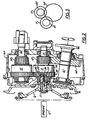
Fig. 1 is a longitudinal cross-sectional view through a clutch made in accordance with the present invention and also includes a schematic diagram of the control system therefor; -
Fig. 2 is a longitudinal cross-sectional view through a transmission of the present invention and includes a showing of both the forward and reverse clutches, the rear clutch being rotated around the input shaft from its normal position and into a plane with the forward clutch for clarity in the drawings; -
Fig. 3 is a transverse, cross-sectional, schematic view on a reduced scale showing the usual relative positions of the two clutches and the output shaft as shown inFig. 2 ; -
Figs. 4 and 5 are enlarged fragmentary views of the trigger valve shown inFigs. 1 and2 and shown, respectively, in the closed and open position; -
Fig. 6 is a graph showing the characteristics of the clutch wherein the position of the control lever in degrees is plotted against the engine rpm, the clutch rpm, and the engine/clutch rpm; and -
Fig..7 is a side elevational view of a marine craft utilizing the present invention. - As shown in
Fig. 1 , the present invention relates to a forward clutch F of the type having interleaved friction plates some of which are splined respectively to ahollow cylinder housing 10 that is fixed to a power input shaft 11 on which it is mounted for rotation therewith and driven by engine E (Fig. 2 ) through input coupling G splined to shaft 11. The other interleaved plates are splined to theoutput gear 12 as is conventional. A spring 14 mounted around shaft 11 and at one end bears against an axially fixedsnap ring 15. The other end of the spring acts against theclutch piston 17 that is slidable in thechamber 18, to urge the piston to a clutch disengaged position. - It will be noted that the
annular piston 17 has asmaller area 20, which defines with thehousing 10 and small clutch actuating chamber 21. Thepiston 17 also has alarger area 24, which with the housing defines a largeclutch actuating chamber 25. - A
fluid passage 30 is rifle drilled in shaft 11 for conducting pressure fluid from aproportional valve 70, and through across port 31 to thesmall piston area 20. - A spring loaded
trigger valve 35, shown on an enlarged scale inFigs. 4 and 5 , is located inpassage 30 and thehead 35 of the valve acts under the action of the spring 36 and against valve seat 37 formed in thepassage 30.Fluid passage 40places fluid passage 30 in communication with the large area of thechamber 25 when pressure fluid inpassage 30 is great enough to compress spring 36. - As shown in
Fig. 2 , the forward clutch F and reverse clutch R are in constant mesh with one another through their annularexternal gears propeller shaft 61, which is suitably journaled in thegear transmission case 64.Shaft 62 of the reverse clutch R, shaft 11 of the forward shaft and thepropeller shaft 61 are all suitably journaled in thegear casing 64 on conventional antifriction tapered roller bearings as shown. The forward clutch F shown and described inFig. 1 is the same as the reverse clutch R and further description of the reverse clutch is deemed to be neither necessary nor desirable. - As shown in schematic
Fig. 3 , thegears - Referring to the schematic diagram in the control system in
Fig. 1 , a control lever L is utilized, through an electronic controller EC, to select operation of the either the forward or the reverse clutch. When the lever L is moved to the right, it causes actuation of the forward clutch. Conversely, when the lever L is moved to the left, it causes actuation of the reverse clutch. It will be noted that the lever has a troll position in either forward or reverse. When the lever is moved from neutral to the troll position, the clutch operates in a troll mode. Then further movement of the lever acts to cause increase in engine speed. As shown inFig. 6 , when the lever reaches the 40° mark, continued movement of the lever increases the engine/clutch rpm as shown. It also increases the clutch pressure as shown on the right-hand side of the graph. Theproportional valve 70 is provided for the forward clutch F and a proportional valve 72 is provided for the reverse clutch R.Proportional valves 70 and 72 are similar and operate to draw pressure fluid from thesource 73 and direct it to either clutch F or clutch R, respectively. Pressure fluid is also directed to a main regulator 75 (Fig. 1 ) andlubrication passage 76 for lubricating the drive plates and bearings of the clutches via the rifle drilling 77 in the shaft and in the known manner. - Generally, the electronic control (EC) is microprocessor-based and sends a pulse width modulated (PWM) signal to control the
proportional valves 70 and 72 for each clutch. The level of the PWM signal sent to the valves is directly related to the position of lever L. By utilizing thesmall area 20 of the clutch, a wide pressure differential is realized to modulate the clutch. Thus, the electronic control (EC) is programmable to allow the engine speed to match the propeller horsepower selected for clutch synchronization. - The present invention provides for a marine Transmission system for variable speed control comprising an electronic control system and dual area clutch pistons. Clutch capacity is varied by separate fluid areas to the clutch, one area being smaller than the other. The marine transmission clutch is modulated via the small area of the piston utilizing a selectively operable control allowing variable propeller speed. Fluid is supplied to the small area by controlling a proportional valve via the control. Modulation offers enhanced docking control and vessel positioning. At a predetermined level, a spring biased trigger valve controls the fluid to the large area of the piston to reach full clutch capacity.
- The initial actuation or modulation of the clutch is utilized, for example, for marine boats for docking and vessel positioning. The fluid pump P (
Fig. 1 ) which supplies fluid to theproportional valves 70 or 72 provides fluid pressure. The lever L in the quadrant shown inFig. 1 , which is movable from a neutral position to a detent position and then to forward position, actuates the valves. Similarly, the quadrant can be swung in the opposite direction for reverse of the transmission when fluid is directed to the other proportional valve 72 for reverse operation of the Transmission. In either direction, pressure fluid is first admitted to thesmall area 20 behind thepiston 17 and after it reaches a certain pressure, the piston is urged to open against the pressure of its spring 14 and permit pressure fluid to flow to the large area behind the piston. The arrangement provides for a variable speed control and clutch capacity is varied by separate fluid areas of the clutch, one area being smaller than the other area. The transmission clutches are modulated via the small area of the piston utilizing a selectively operable control allowing variable output speed. - Modulation of the clutch offers docking control and vessel positioning. Then at a predetermined pressure level, the spring biased trigger valve controls the flow of fluid to the large area of the piston to thereby cause it to reach full clutch capacity. This system provides seamless transition from modulation to full engagement. During modulation, engine speed can be increased slightly. After modulation the engine throttle is controlled.
- By locating the trigger valve in the center shaft of the clutch, it is not influenced by centrifugal speed of the clutch. Furthermore, the present trigger valve in its operation is much simpler than the prior art triggering valve. This provides for immediate response during modulation and the engine speed can be increased slightly and accurately in either direction to provide precise and rapid back and forth changes in speed for maneuvering, for example, of the boat during the docking procedure.
Claims (10)
- A modulatable power transmission clutch (F; R) including interleaved clutch plates, said clutch having a central power transmitting shaft (11) extending axially through said clutch mounted thereon, said clutch including a fluid operated movable piston (17) for effecting clutch operation by compression of said plates, said piston (17)having smaller and larger piston areas (20, 24) thereon, the smaller piston area (20) being adapted to have fluid flow directed thereto at a variable fluid pressure whereby said clutch is modulatable, the larger piston area (24) being adapted to have fluid flow directed thereto to effect maximum and unmodulatable engagement of said clutch;
and a spring loaded normally closed valve (35) for controlling fluid flow to said larger piston area (24) in response to fluid pressure above a predetermined amount at said smaller piston area (20), said valve (35) being normally closed whereby pressure fluid is directed to said smaller piston area (20) at a variable fluid pressure whereby said clutch is modulatable, and when said valve (35) is open by said fluid pressure over a predetermined amount permits fluid flow to said larger piston area (24) to effect maximum and unmodulatable engagement of said clutch for full clutch capacity, characterized In that said valve (35) is axially slidably mounted in an axially extending hole (30) in said shaft (11). - A modulatable power transmission clutch according to claim 1, wherein a pressure fluid passage (30) is provided In said shaft (11) for conducting pressure fluid to said smaller area (20) and to said larger piston area (24), said trigger valve (35) being located in said shaft passage (30).
- A marine transmission for variable speed control of a boat having a propeller for providing modulatable lower speed in both forward and reverse direction for maneuvering during docking of said boat to provide enhanced docking control and boat positioning; said transmission providing seamless transition from modulation during which speed can be Increased slightly to full clutch engagement and capacity for driving said propeller;
said transmission including a modulatable power transmission clutch (F, R) including interleaved clutch plates, said clutch comprising a power transmitting shaft (11) extending axially and centrally through said clutch mounted thereon, said clutch including a fluid operated movable piston (17) for effecting clutch operation by compression of said plates, said piston (17) having two separate fluid application piston areas (20, 24) of different areas thereon, one smaller of said piston areas (20) being adapted to have fluid flow directed thereto at a variable fluid pressure whereby said clutch is modulatable for said docking, the other larger of said piston areas (24) being adapted to have fluid flow directed thereto to effect maximum and unmodulatable engagement of said clutch for driving said propeller,
and valve means (35) for controlling fluid flow to said other larger of said piston areas in response to fluid pressure above a predetermined amount at said one smaller of said piston areas, said valve means (35) being spring loaded to a normally closed position in which pressure fluid is directed to said one smaller piston area at a variable fluid pressure whereby said clutch is modulatable, and when said valve means is open it permits fluid flow to said other larger of said piston area to effect maximum and unmodulatable engagement of said clutch for full clutch capacity available to said propeller, characterized In that said valve means (35) is axially slidably mounted in an axially extending hole (30) in said shaft (11). - A power transmission including a forward modulatable power transmission clutch (F) and a rear modulatable power transmission clutch (R), said forward clutch connected in power receiving connection with a prime mover (E) and in power delivering connection with load (61) to be driven,
said rear clutch (R) being connected in driven engagement with said forward clutch (F) and engageable with said load to be driven for driving the latter in a reverse direction,
said forward and rear clutches each including clutch plates, a power transmitting shaft (11) extending axially and centrally therethrough, said clutch including a fluid operated movable piston (17) for effecting clutch operation by compression of said plates, said piston (17) having two separate fluid application piston areas (20, 24) of different areas thereon, one smaller of said piston areas being adapted to have fluid flow directed thereto at a variable fluid pressure whereby said clutch is modulatable, the other larger of said piston areas being adapted to have fluid flow directed thereto to effect maximum and unmodulatable engagement of said clutch;
and valve means (35) for controlling fluid flow to said other larger of said piston areas in response to fluid pressure above a predetermined amount at said one smaller of said piston areas, said valve means (35) being spring loaded to a normally closed position in which pressure fluid is directed to said one smaller piston area at a variable fluid pressure whereby said clutch is modulatable, and when said valve means (35) is open it permits fluid flow to said other larger of said piston area to effect maximum and unmodulatable engagement of said clutch for full clutch capacity, characterized in that said valve means (35) is axially slidably mounted in an axially extending hole (30) in said shaft (11). - A power transmission including according to claim 4, wherein
a pressure fluid passage (30) in said shaft (11) is provided for conducting pressure fluid to said smaller area (20) and to said larger piston area (24), said trigger valve (35) being located In said shaft passage (30). - A marine transmission according to claim 3, wherein said transmission includes a forward modulatable power transmission clutch (F) and a rear modulatable power transmission clutch (R), said forward clutch connected in power receiving connection with a prime mover and in power delivering connection with load (61) to be driven,
said rear clutch(R) being connected in driven engagement with said forward clutch (F) and engageable with said load to be driven for driving the latter in a reverse direction,
an electronic control circuit for said transmission is provided including a source of pressure fluid (73), a proportional valve (70) connected to said source for delivering pressure fluid to said rear clutch (R), said source connected to another proportional valve (72) for delivering pressure fluid to said forward clutch (F),
said circuit also including a control lever (L) operatively connected with said proportional valves (70, 72) for selective operation thereof to effect forward or reverse operation of said boat - The modulatable power transmission clutch of claim 1 or 2, wherein a single valve (35) is fluidly connected to each of the smaller and larger piston areas (20, 24).
- The modulatable power transmission clutch of claim 1 or 2, wherein modulating the clutch enhances docking control.
- The modulatable power transmission clutch of claim 1 or 2, wherein modulating the clutch enhances vessel positioning.
- The modulatable power transmission clutch of claim 1 or 2, wherein the power transmission clutch allows seamless transition from a modulation phase during which a clutch output speed can be increased slightly to a full clutch engagement and capacity phase.
Applications Claiming Priority (3)
| Application Number | Priority Date | Filing Date | Title |
|---|---|---|---|
| US09/765,117 US6443286B1 (en) | 2001-01-18 | 2001-01-18 | Modulatable power transmission clutch and a marine transmission |
| US765117 | 2001-01-18 | ||
| PCT/US2002/001414 WO2002057652A2 (en) | 2001-01-18 | 2002-01-15 | Modulatable power transmission clutch and a marine transmission |
Publications (3)
| Publication Number | Publication Date |
|---|---|
| EP1352178A2 EP1352178A2 (en) | 2003-10-15 |
| EP1352178A4 EP1352178A4 (en) | 2006-03-22 |
| EP1352178B1 true EP1352178B1 (en) | 2012-09-05 |
Family
ID=25072690
Family Applications (1)
| Application Number | Title | Priority Date | Filing Date |
|---|---|---|---|
| EP02703149A Expired - Lifetime EP1352178B1 (en) | 2001-01-18 | 2002-01-15 | Modulatable power transmission clutch and a marine transmission |
Country Status (11)
| Country | Link |
|---|---|
| US (1) | US6443286B1 (en) |
| EP (1) | EP1352178B1 (en) |
| JP (1) | JP4004406B2 (en) |
| KR (1) | KR100539039B1 (en) |
| CN (1) | CN1252397C (en) |
| AU (1) | AU2002236785B2 (en) |
| BR (1) | BR0206447B1 (en) |
| DK (1) | DK1352178T3 (en) |
| ES (1) | ES2394484T3 (en) |
| HK (1) | HK1059638A1 (en) |
| WO (1) | WO2002057652A2 (en) |
Cited By (1)
| Publication number | Priority date | Publication date | Assignee | Title |
|---|---|---|---|---|
| CN102913562A (en) * | 2012-10-15 | 2013-02-06 | 浙江大学 | Hydro-viscous speed regulation device |
Families Citing this family (42)
| Publication number | Priority date | Publication date | Assignee | Title |
|---|---|---|---|---|
| US6679740B1 (en) * | 1999-09-02 | 2004-01-20 | Yanmar Diesel Engine Co., Ltd. | Method of hydraulically controlling a marine speed reducing and reversing machine in crash astern operation |
| US6761600B2 (en) * | 2000-03-27 | 2004-07-13 | Reintjes Gmbh | Marine gear and a method for preventing a drop in motor speed when engaging a multi-plate clutch |
| JP2003301861A (en) * | 2002-04-05 | 2003-10-24 | Nsk Warner Kk | Multiple disc clutch |
| US6666312B2 (en) * | 2002-04-24 | 2003-12-23 | Twin Disc, Incorporated | Modulatable power transmission clutch and a marine transmission |
| US7059460B2 (en) * | 2003-02-14 | 2006-06-13 | Ford Motor Company | Hydraulic coupling system |
| US7007782B2 (en) * | 2003-02-14 | 2006-03-07 | Automotive Components Holdings Llc | Control of a hydraulic coupling system |
| GB0310969D0 (en) * | 2003-05-13 | 2003-06-18 | Ricardo Uk Linmited | Clutches |
| US7267365B2 (en) * | 2004-03-10 | 2007-09-11 | Automotive Systems Laboratory, Inc. | Inflator |
| US7387348B2 (en) * | 2005-02-11 | 2008-06-17 | Oshkosh Truck Company | Pump and roll system for a vehicle |
| WO2007081249A1 (en) * | 2006-01-16 | 2007-07-19 | Ab Volvo Penta | Method of measuring coupling ratios |
| US7793768B2 (en) * | 2006-02-27 | 2010-09-14 | George Reisch Aschauer | Motor driven ball and ramp clutching system for a marine transmission |
| US8608441B2 (en) | 2006-06-12 | 2013-12-17 | Energyield Llc | Rotatable blade apparatus with individually adjustable blades |
| US8157070B2 (en) * | 2006-07-25 | 2012-04-17 | Yanmar Co., Ltd. | Marine reduction and reverse gear unit |
| DE102006042078B4 (en) * | 2006-09-05 | 2012-04-26 | Ortlinghaus-Werke Gmbh | Clutch with a first and a second piston-cylinder unit |
| EP1900633A1 (en) | 2006-09-15 | 2008-03-19 | Yellowfin Limited | Marine propulsion and constructional details thereof |
| EP1900634A1 (en) | 2006-09-15 | 2008-03-19 | Yellowfin Limited | Marine propulsion and constructional details thereof |
| EP1900631A1 (en) | 2006-09-15 | 2008-03-19 | Yellowfin Limited | Marine propulsion and constructional details thereof |
| EP1900632A1 (en) | 2006-09-15 | 2008-03-19 | Yellowfin Limited | Marine propulsion and constructional details thereof |
| EP1900636A1 (en) | 2006-09-15 | 2008-03-19 | Yellowfin Limited | Marine propulsion and constructional details thereof |
| EP1900630A1 (en) | 2006-09-15 | 2008-03-19 | Yellowfin Limited | Marine propulsion and constructional details thereof |
| US20100144219A1 (en) * | 2008-12-05 | 2010-06-10 | Brunswick Corporation | Marine Vessel Hybrid Propulsion System |
| US8393926B2 (en) * | 2009-02-12 | 2013-03-12 | Twin Disc, Inc. | Hybrid marine power train system |
| US9533747B2 (en) * | 2010-02-08 | 2017-01-03 | Brunswick Corporation | Systems and methods for controlling battery performance in hybrid marine propulsion systems |
| US8682516B1 (en) | 2010-10-22 | 2014-03-25 | Brunswick Corporation | Systems and methods for powering hybrid marine propulsion systems |
| JP5634213B2 (en) * | 2010-10-27 | 2014-12-03 | ヤンマー株式会社 | Ship propulsion device |
| US9054555B1 (en) | 2011-03-22 | 2015-06-09 | Brunswick Corporation | Methods and systems for charging a rechargeable battery device on a marine vessel |
| US8608521B1 (en) | 2011-05-03 | 2013-12-17 | Brunswick Corporation | Mission-based systems and methods for operating hybrid propulsion systems for marine vessels |
| US8939270B2 (en) * | 2012-04-16 | 2015-01-27 | Gm Global Technology Operations, Llc | Tabbed separation clutch plate |
| US9751603B2 (en) * | 2012-05-10 | 2017-09-05 | Samsung Heavy Ind. Co., Ltd. | Propulsion device for ship and ship comprising the same |
| US8808139B1 (en) | 2012-05-18 | 2014-08-19 | Brunswick Corporation | Hybrid marine propulsion systems having programmable clutch operations |
| US8992274B1 (en) | 2012-06-15 | 2015-03-31 | Brunswick Corporation | Systems and methods for manually operating hybrid propulsion and regeneration systems for marine vessels |
| CN102788150B (en) * | 2012-07-28 | 2015-07-08 | 四川大学 | Novel hydraulic gear-shifting pressure regulating valve |
| US8762022B1 (en) | 2012-08-17 | 2014-06-24 | Brunswick Corporation | Marine propulsion system with efficient engine speed delta |
| CN102927266B (en) * | 2012-11-09 | 2015-06-17 | 四川大学 | Pressure control valve capable of shifting gears through hydraulic pressure |
| US8725329B1 (en) | 2013-02-07 | 2014-05-13 | Brunswick Corporation | Schedule-based methods and systems for controlling hybrid marine propulsion systems |
| CN103335030B (en) * | 2013-05-29 | 2015-09-02 | 中国人民解放军海军工程大学 | Marine impact cut-off type safety coupling |
| CN103671620A (en) * | 2013-12-03 | 2014-03-26 | 天津工程机械研究院 | Hydraulic pump clutch for engineering machines |
| JP6765531B2 (en) * | 2017-06-27 | 2020-10-07 | ジーケーエヌ オートモーティブ リミテッド | Fluid pressure clutch |
| JP6940368B2 (en) * | 2017-10-17 | 2021-09-29 | 川崎重工業株式会社 | Wet multi-plate clutch and marine propulsion device |
| WO2019158280A1 (en) * | 2018-02-19 | 2019-08-22 | Zf Friedrichshafen Ag | Disk clutch assembly |
| GB2574263B (en) * | 2018-06-01 | 2020-09-30 | Caterpillar Sarl | Disconnect clutch |
| DE102018222514B4 (en) * | 2018-12-20 | 2022-08-04 | Audi Ag | drive device |
Family Cites Families (10)
| Publication number | Priority date | Publication date | Assignee | Title |
|---|---|---|---|---|
| US3243026A (en) * | 1964-05-28 | 1966-03-29 | Twin Disc Clutch Co | Hydraulic clutch with multiple pistons |
| US4070926A (en) * | 1975-12-22 | 1978-01-31 | Twin Disc, Incorporated | Swing control for crane |
| US4186829A (en) | 1977-11-14 | 1980-02-05 | Twin Disc, Incorporated | Modulatable power transmission clutch |
| US4459873A (en) | 1982-02-22 | 1984-07-17 | Twin Disc, Incorporated | Marine propulsion system |
| US4451238A (en) | 1982-09-07 | 1984-05-29 | Twin Disc, Incorporated | Shaft brake for marine propulsion system |
| US4836809A (en) | 1988-03-11 | 1989-06-06 | Twin Disc, Incorporated | Control means for marine propulsion system |
| US4969546A (en) * | 1989-07-27 | 1990-11-13 | General Motors Corporation | Fluid operated clutch with a directional torque control |
| JP3111768B2 (en) * | 1993-08-24 | 2000-11-27 | トヨタ自動車株式会社 | Automatic transmission friction engagement device |
| JP3221329B2 (en) * | 1996-10-01 | 2001-10-22 | 日産自動車株式会社 | Rotary clutch device for automatic transmission |
| JPH1137176A (en) * | 1997-07-24 | 1999-02-09 | Exedy Corp | Clutch operating piston structure |
-
2001
- 2001-01-18 US US09/765,117 patent/US6443286B1/en not_active Expired - Lifetime
-
2002
- 2002-01-15 AU AU2002236785A patent/AU2002236785B2/en not_active Expired
- 2002-01-15 DK DK02703149.1T patent/DK1352178T3/en active
- 2002-01-15 ES ES02703149T patent/ES2394484T3/en not_active Expired - Lifetime
- 2002-01-15 JP JP2002557692A patent/JP4004406B2/en not_active Expired - Fee Related
- 2002-01-15 BR BRPI0206447-2A patent/BR0206447B1/en not_active IP Right Cessation
- 2002-01-15 WO PCT/US2002/001414 patent/WO2002057652A2/en active IP Right Grant
- 2002-01-15 CN CNB028032896A patent/CN1252397C/en not_active Expired - Fee Related
- 2002-01-15 KR KR10-2003-7007067A patent/KR100539039B1/en not_active IP Right Cessation
- 2002-01-15 EP EP02703149A patent/EP1352178B1/en not_active Expired - Lifetime
-
2004
- 2004-04-13 HK HK04102573.7A patent/HK1059638A1/en not_active IP Right Cessation
Cited By (2)
| Publication number | Priority date | Publication date | Assignee | Title |
|---|---|---|---|---|
| CN102913562A (en) * | 2012-10-15 | 2013-02-06 | 浙江大学 | Hydro-viscous speed regulation device |
| CN102913562B (en) * | 2012-10-15 | 2015-02-11 | 浙江大学 | Hydro-viscous speed regulation device |
Also Published As
| Publication number | Publication date |
|---|---|
| JP4004406B2 (en) | 2007-11-07 |
| US6443286B1 (en) | 2002-09-03 |
| JP2004518086A (en) | 2004-06-17 |
| HK1059638A1 (en) | 2004-07-09 |
| WO2002057652A3 (en) | 2002-12-27 |
| EP1352178A4 (en) | 2006-03-22 |
| BR0206447A (en) | 2003-12-30 |
| WO2002057652A2 (en) | 2002-07-25 |
| CN1252397C (en) | 2006-04-19 |
| ES2394484T3 (en) | 2013-02-01 |
| DK1352178T3 (en) | 2012-10-29 |
| US20020094903A1 (en) | 2002-07-18 |
| BR0206447B1 (en) | 2011-08-09 |
| KR20040011437A (en) | 2004-02-05 |
| KR100539039B1 (en) | 2005-12-27 |
| EP1352178A2 (en) | 2003-10-15 |
| AU2002236785B2 (en) | 2006-03-02 |
| CN1479844A (en) | 2004-03-03 |
Similar Documents
| Publication | Publication Date | Title |
|---|---|---|
| EP1352178B1 (en) | Modulatable power transmission clutch and a marine transmission | |
| AU2002236785A1 (en) | Modulatable power transmission clutch and a marine transmission | |
| EP1499527B1 (en) | Modulatable power transmission clutch and a marine transmission | |
| US8852049B2 (en) | Fast valve actuation system for an automatic transmission | |
| US4535652A (en) | Automatic transmission and direct coupling clutch for vehicle | |
| EP3419851B1 (en) | Transmission internal pto clutch and method of control | |
| EP3419850B1 (en) | Transmission internal pto clutch and method of control | |
| US6059534A (en) | Control system for hydraulic drive | |
| CA1039618A (en) | Combination pressure control selector valve | |
| US4262781A (en) | Hydraulic retarder for multi-speed power transmissions | |
| US3833100A (en) | Control system for a power transmission clutch | |
| EP3336382B1 (en) | Direct drive pivot and pivot lockup of a transmission system and method thereof | |
| CA1055806A (en) | Engine and transmission control system | |
| JP2007509292A (en) | Decoupling clutch especially for ships | |
| JP2018203170A (en) | Marine gear device | |
| JPH0343870B2 (en) |
Legal Events
| Date | Code | Title | Description |
|---|---|---|---|
| PUAI | Public reference made under article 153(3) epc to a published international application that has entered the european phase |
Free format text: ORIGINAL CODE: 0009012 |
|
| 17P | Request for examination filed |
Effective date: 20030717 |
|
| AK | Designated contracting states |
Kind code of ref document: A2 Designated state(s): AT BE CH CY DE DK ES FI FR GB GR IE IT LI LU MC NL PT SE TR |
|
| AX | Request for extension of the european patent |
Extension state: AL LT LV MK RO SI |
|
| REG | Reference to a national code |
Ref country code: HK Ref legal event code: DE Ref document number: 1059638 Country of ref document: HK |
|
| A4 | Supplementary search report drawn up and despatched |
Effective date: 20060202 |
|
| 17Q | First examination report despatched |
Effective date: 20080306 |
|
| GRAP | Despatch of communication of intention to grant a patent |
Free format text: ORIGINAL CODE: EPIDOSNIGR1 |
|
| GRAJ | Information related to disapproval of communication of intention to grant by the applicant or resumption of examination proceedings by the epo deleted |
Free format text: ORIGINAL CODE: EPIDOSDIGR1 |
|
| GRAP | Despatch of communication of intention to grant a patent |
Free format text: ORIGINAL CODE: EPIDOSNIGR1 |
|
| GRAC | Information related to communication of intention to grant a patent modified |
Free format text: ORIGINAL CODE: EPIDOSCIGR1 |
|
| GRAJ | Information related to disapproval of communication of intention to grant by the applicant or resumption of examination proceedings by the epo deleted |
Free format text: ORIGINAL CODE: EPIDOSDIGR1 |
|
| GRAP | Despatch of communication of intention to grant a patent |
Free format text: ORIGINAL CODE: EPIDOSNIGR1 |
|
| RBV | Designated contracting states (corrected) |
Designated state(s): DE DK ES FR GB IT |
|
| GRAC | Information related to communication of intention to grant a patent modified |
Free format text: ORIGINAL CODE: EPIDOSCIGR1 |
|
| GRAS | Grant fee paid |
Free format text: ORIGINAL CODE: EPIDOSNIGR3 |
|
| GRAA | (expected) grant |
Free format text: ORIGINAL CODE: 0009210 |
|
| AK | Designated contracting states |
Kind code of ref document: B1 Designated state(s): DE DK ES FR GB IT |
|
| REG | Reference to a national code |
Ref country code: GB Ref legal event code: FG4D |
|
| REG | Reference to a national code |
Ref country code: DK Ref legal event code: T3 |
|
| REG | Reference to a national code |
Ref country code: DE Ref legal event code: R096 Ref document number: 60243645 Country of ref document: DE Effective date: 20121031 |
|
| REG | Reference to a national code |
Ref country code: ES Ref legal event code: FG2A Ref document number: 2394484 Country of ref document: ES Kind code of ref document: T3 Effective date: 20130201 |
|
| REG | Reference to a national code |
Ref country code: HK Ref legal event code: GR Ref document number: 1059638 Country of ref document: HK |
|
| PLBE | No opposition filed within time limit |
Free format text: ORIGINAL CODE: 0009261 |
|
| STAA | Information on the status of an ep patent application or granted ep patent |
Free format text: STATUS: NO OPPOSITION FILED WITHIN TIME LIMIT |
|
| 26N | No opposition filed |
Effective date: 20130606 |
|
| REG | Reference to a national code |
Ref country code: DE Ref legal event code: R097 Ref document number: 60243645 Country of ref document: DE Effective date: 20130606 |
|
| PGFP | Annual fee paid to national office [announced via postgrant information from national office to epo] |
Ref country code: DK Payment date: 20150126 Year of fee payment: 14 |
|
| REG | Reference to a national code |
Ref country code: FR Ref legal event code: PLFP Year of fee payment: 15 |
|
| REG | Reference to a national code |
Ref country code: DK Ref legal event code: EBP Effective date: 20160131 |
|
| REG | Reference to a national code |
Ref country code: FR Ref legal event code: PLFP Year of fee payment: 16 |
|
| PG25 | Lapsed in a contracting state [announced via postgrant information from national office to epo] |
Ref country code: DK Free format text: LAPSE BECAUSE OF NON-PAYMENT OF DUE FEES Effective date: 20160131 |
|
| REG | Reference to a national code |
Ref country code: FR Ref legal event code: PLFP Year of fee payment: 17 |
|
| PGFP | Annual fee paid to national office [announced via postgrant information from national office to epo] |
Ref country code: FR Payment date: 20210120 Year of fee payment: 20 |
|
| PGFP | Annual fee paid to national office [announced via postgrant information from national office to epo] |
Ref country code: DE Payment date: 20210114 Year of fee payment: 20 Ref country code: ES Payment date: 20210217 Year of fee payment: 20 Ref country code: GB Payment date: 20210122 Year of fee payment: 20 |
|
| PGFP | Annual fee paid to national office [announced via postgrant information from national office to epo] |
Ref country code: IT Payment date: 20210129 Year of fee payment: 20 |
|
| REG | Reference to a national code |
Ref country code: DE Ref legal event code: R071 Ref document number: 60243645 Country of ref document: DE |
|
| REG | Reference to a national code |
Ref country code: GB Ref legal event code: PE20 Expiry date: 20220114 |
|
| REG | Reference to a national code |
Ref country code: ES Ref legal event code: FD2A Effective date: 20220426 |
|
| PG25 | Lapsed in a contracting state [announced via postgrant information from national office to epo] |
Ref country code: GB Free format text: LAPSE BECAUSE OF EXPIRATION OF PROTECTION Effective date: 20220114 |
|
| PG25 | Lapsed in a contracting state [announced via postgrant information from national office to epo] |
Ref country code: ES Free format text: LAPSE BECAUSE OF EXPIRATION OF PROTECTION Effective date: 20220116 |