EP1867423A1 - Procédé de réparation d'une pièce par brasage d'une tôle revêtue de brasure - Google Patents
Procédé de réparation d'une pièce par brasage d'une tôle revêtue de brasure Download PDFInfo
- Publication number
- EP1867423A1 EP1867423A1 EP06012072A EP06012072A EP1867423A1 EP 1867423 A1 EP1867423 A1 EP 1867423A1 EP 06012072 A EP06012072 A EP 06012072A EP 06012072 A EP06012072 A EP 06012072A EP 1867423 A1 EP1867423 A1 EP 1867423A1
- Authority
- EP
- European Patent Office
- Prior art keywords
- solder
- sheet metal
- sheet
- soldering
- turbine blade
- Prior art date
- Legal status (The legal status is an assumption and is not a legal conclusion. Google has not performed a legal analysis and makes no representation as to the accuracy of the status listed.)
- Withdrawn
Links
Images


Classifications
-
- B—PERFORMING OPERATIONS; TRANSPORTING
- B23—MACHINE TOOLS; METAL-WORKING NOT OTHERWISE PROVIDED FOR
- B23P—METAL-WORKING NOT OTHERWISE PROVIDED FOR; COMBINED OPERATIONS; UNIVERSAL MACHINE TOOLS
- B23P6/00—Restoring or reconditioning objects
- B23P6/002—Repairing turbine components, e.g. moving or stationary blades, rotors
- B23P6/005—Repairing turbine components, e.g. moving or stationary blades, rotors using only replacement pieces of a particular form
-
- B—PERFORMING OPERATIONS; TRANSPORTING
- B23—MACHINE TOOLS; METAL-WORKING NOT OTHERWISE PROVIDED FOR
- B23K—SOLDERING OR UNSOLDERING; WELDING; CLADDING OR PLATING BY SOLDERING OR WELDING; CUTTING BY APPLYING HEAT LOCALLY, e.g. FLAME CUTTING; WORKING BY LASER BEAM
- B23K1/00—Soldering, e.g. brazing, or unsoldering
- B23K1/0008—Soldering, e.g. brazing, or unsoldering specially adapted for particular articles or work
- B23K1/0018—Brazing of turbine parts
-
- B—PERFORMING OPERATIONS; TRANSPORTING
- B23—MACHINE TOOLS; METAL-WORKING NOT OTHERWISE PROVIDED FOR
- B23K—SOLDERING OR UNSOLDERING; WELDING; CLADDING OR PLATING BY SOLDERING OR WELDING; CUTTING BY APPLYING HEAT LOCALLY, e.g. FLAME CUTTING; WORKING BY LASER BEAM
- B23K1/00—Soldering, e.g. brazing, or unsoldering
- B23K1/19—Soldering, e.g. brazing, or unsoldering taking account of the properties of the materials to be soldered
-
- B—PERFORMING OPERATIONS; TRANSPORTING
- B23—MACHINE TOOLS; METAL-WORKING NOT OTHERWISE PROVIDED FOR
- B23K—SOLDERING OR UNSOLDERING; WELDING; CLADDING OR PLATING BY SOLDERING OR WELDING; CUTTING BY APPLYING HEAT LOCALLY, e.g. FLAME CUTTING; WORKING BY LASER BEAM
- B23K35/00—Rods, electrodes, materials, or media, for use in soldering, welding, or cutting
- B23K35/02—Rods, electrodes, materials, or media, for use in soldering, welding, or cutting characterised by mechanical features, e.g. shape
- B23K35/0222—Rods, electrodes, materials, or media, for use in soldering, welding, or cutting characterised by mechanical features, e.g. shape for use in soldering, brazing
- B23K35/0233—Sheets, foils
- B23K35/0238—Sheets, foils layered
-
- B—PERFORMING OPERATIONS; TRANSPORTING
- B23—MACHINE TOOLS; METAL-WORKING NOT OTHERWISE PROVIDED FOR
- B23K—SOLDERING OR UNSOLDERING; WELDING; CLADDING OR PLATING BY SOLDERING OR WELDING; CUTTING BY APPLYING HEAT LOCALLY, e.g. FLAME CUTTING; WORKING BY LASER BEAM
- B23K35/00—Rods, electrodes, materials, or media, for use in soldering, welding, or cutting
- B23K35/22—Rods, electrodes, materials, or media, for use in soldering, welding, or cutting characterised by the composition or nature of the material
- B23K35/24—Selection of soldering or welding materials proper
- B23K35/30—Selection of soldering or welding materials proper with the principal constituent melting at less than 1550 degrees C
-
- F—MECHANICAL ENGINEERING; LIGHTING; HEATING; WEAPONS; BLASTING
- F01—MACHINES OR ENGINES IN GENERAL; ENGINE PLANTS IN GENERAL; STEAM ENGINES
- F01D—NON-POSITIVE DISPLACEMENT MACHINES OR ENGINES, e.g. STEAM TURBINES
- F01D5/00—Blades; Blade-carrying members; Heating, heat-insulating, cooling or antivibration means on the blades or the members
- F01D5/005—Repairing methods or devices
-
- B—PERFORMING OPERATIONS; TRANSPORTING
- B23—MACHINE TOOLS; METAL-WORKING NOT OTHERWISE PROVIDED FOR
- B23K—SOLDERING OR UNSOLDERING; WELDING; CLADDING OR PLATING BY SOLDERING OR WELDING; CUTTING BY APPLYING HEAT LOCALLY, e.g. FLAME CUTTING; WORKING BY LASER BEAM
- B23K2101/00—Articles made by soldering, welding or cutting
- B23K2101/001—Turbines
-
- F—MECHANICAL ENGINEERING; LIGHTING; HEATING; WEAPONS; BLASTING
- F05—INDEXING SCHEMES RELATING TO ENGINES OR PUMPS IN VARIOUS SUBCLASSES OF CLASSES F01-F04
- F05D—INDEXING SCHEME FOR ASPECTS RELATING TO NON-POSITIVE-DISPLACEMENT MACHINES OR ENGINES, GAS-TURBINES OR JET-PROPULSION PLANTS
- F05D2230/00—Manufacture
- F05D2230/20—Manufacture essentially without removing material
- F05D2230/23—Manufacture essentially without removing material by permanently joining parts together
- F05D2230/232—Manufacture essentially without removing material by permanently joining parts together by welding
- F05D2230/238—Soldering
-
- Y—GENERAL TAGGING OF NEW TECHNOLOGICAL DEVELOPMENTS; GENERAL TAGGING OF CROSS-SECTIONAL TECHNOLOGIES SPANNING OVER SEVERAL SECTIONS OF THE IPC; TECHNICAL SUBJECTS COVERED BY FORMER USPC CROSS-REFERENCE ART COLLECTIONS [XRACs] AND DIGESTS
- Y02—TECHNOLOGIES OR APPLICATIONS FOR MITIGATION OR ADAPTATION AGAINST CLIMATE CHANGE
- Y02T—CLIMATE CHANGE MITIGATION TECHNOLOGIES RELATED TO TRANSPORTATION
- Y02T50/00—Aeronautics or air transport
- Y02T50/60—Efficient propulsion technologies, e.g. for aircraft
Definitions
- the present invention relates to a method for repairing a component, in particular a gas turbine component.
- Components such as components of a gas turbine, are exposed during operation conditions that lead to depressions and cracks in the components.
- components of a gas turbine are exposed during operation conditions that lead to depressions and cracks in the components.
- base material is achieved by various methods such as build-up welding, flame spraying or soldering with paste or pre-sintered preforms (PSP).
- PPS paste or pre-sintered preforms
- solder To be repaired depressions and cracks in the components can still be filled with a solder.
- commonly used solders have lower mechanical characteristics than the base material of the component. The mechanical properties are limited by the solder.
- the reduced by the operating stress wall thicknesses or depressions formed on gas turbine components by thermal spraying of similar materials (for example, vacuum plasma spraying or high-speed flame spraying) in the contour can be restored. Because of the quasi superplastic (creep) behavior of these layers under operating stress, they do not contribute to the strength of the component.
- a component can be repaired by attaching custom-made coupon (repair) coupons by welding or soldering.
- custom-made coupon (repair) coupons by welding or soldering.
- a metal sheet is arranged in a location of the component to be repaired.
- the sheet has a layer on solder, by means of which the sheet can be soldered to the component.
- the sheet metal can in particular be made of the base material of the component.
- the solder used may be a low-melting solder, in particular with the addition of a flux, or a high-melting solder, the latter being admixed with a melting point depressant, for example boron.
- the content of typical solder additives such as boron which reduce the mechanical properties as well as the oxidation resistance of the component to be repaired, can be kept small in the repaired area.
- a solid attachment of the sheet is guaranteed to the component to be repaired by the layer of solder.
- the local heat input and problems with the weld pool protection are reduced.
- the Sputter soldering reduces the amount of solder and flux and, when using a refractory solder, reduces entry of melting point depressants, such as boron, into the site to be repaired. Fluxes and melting point depressants can affect both the coating and the mechanical properties of the components.
- a coupon repair is achieved by the adaptability of the sheet a much greater flexibility of the application. It does not have to be made for every damage a fitting. Instead, one or more standard sheets may be deformed to the location to be repaired.
- the layer of solder is subjected to a heat treatment before arranging the sheet at the point to be repaired.
- the solder powder is formed so that there is a minimum cohesion of the solder powder particles, and the solder powder compacts and solidifies, so that the layer of solder is stabilized.
- the sheet is coated on one side with a thin, uniform layer of solder, so that the solder content, and thus the content of flux in the repair area as low as possible, but sufficient to ensure a secure soldering of the sheet with the component.
- the sheet is adapted to the geometry of the point to be repaired. D5ies can be achieved for example by deformation of the sheet. Since sheets with a small thickness are more easily deformable than sheets with a greater thickness, the thickness of the sheet used in the method according to the invention is advantageously low. If necessary, a plurality of sheets, each having a layer of solder, can be individually adapted and stacked on the part of the component to be repaired.
- the component and the sheet are subjected to brazing for a soldering heat treatment.
- soldering heat treatment the solder is melted.
- the solder cools with solidification of the solder particles.
- the sheet is firmly connected to the component, so that the sheet during operation of the component, in particular a gas turbine, does not solve after repair.
- solder is a low-melting solder using a flux
- the soldering heat treatment involves only one treatment step. If, on the other hand, a high-melting solder using a melting point depressant is used, a multi-stage soldering heat treatment is carried out.
- This comprises a first heat treatment at a temperature above the melting temperature of the solder, at which the solder melts with the lowered melting point. This is followed, as a second heat treatment, by a diffusion heat treatment at a temperature below the solution annealing temperature for expelling the melting point depressant by diffusion. This is followed by a third heat treatment at a temperature which is suitable for adjusting the microstructure of the base material in the region of the solder joint and in which no remelting of the solder takes place.
- the component and the sheet are fixed before soldering by means of spot welds, for example using a spot welding method.
- a solder paste is used in at least one edge region of the sheet.
- the solder paste serves to fill any gaps between the edge region of the sheet and the part of the component to be repaired, so that a uniform, firm connection between the sheet and the component is obtained along the entire circumference of the sheet after soldering.
- the component to be repaired by the method according to the invention may in particular be a turbine component, for example a turbine blade.
- the point to be repaired is in particular a trailing edge of the turbine blade.
- Outlet edges of turbine blades are particularly susceptible to wear and tear.
- the inventive method for building wall thickness, in particular in gas turbine components, are used.
- FIG. 1 shows by way of example a gas turbine 100 in a longitudinal partial section.
- the gas turbine 100 has inside a rotatably mounted about a rotation axis 102 rotor 103 with a shaft 101, which is also referred to as a turbine runner.
- an intake housing 104 a compressor 105, for example, a toroidal combustion chamber 110, in particular annular combustion chamber, with a plurality of coaxially arranged burners 107, a turbine 108 and the exhaust housing 109th
- a compressor 105 for example, a toroidal combustion chamber 110, in particular annular combustion chamber, with a plurality of coaxially arranged burners 107, a turbine 108 and the exhaust housing 109th
- the annular combustion chamber 110 communicates with an annular annular hot gas channel 111, for example.
- annular annular hot gas channel 111 for example.
- turbine stages 112 connected in series form the turbine 108.
- Each turbine stage 112 is formed, for example, from two blade rings.
- a series 125 formed of rotor blades 120 follows.
- the guide vanes 130 are fastened to an inner housing 138 of a stator 143, whereas the moving blades 120 of a row 125 are attached to the rotor 103 by means of a turbine disk 133, for example. Coupled to the rotor 103 is a generator or work machine (not shown).
- air 105 is sucked in and compressed by the compressor 105 through the intake housing 104.
- the compressed air provided at the turbine-side end of the compressor 105 is supplied to the burners 107 where it is mixed with a fuel.
- the mixture is then burned to form the working fluid 113 in the combustion chamber 110.
- the working medium 113 flows along the hot gas channel 111 past the guide vanes 130 and the rotor blades 120.
- the working medium 113 expands in a pulse-transmitting manner, so that the rotor blades 120 drive the rotor 103 and drive the machine coupled to it.
- the exposed to the hot working fluid 113 components are subject during operation of the gas turbine 100th thermal loads.
- the guide vanes 130 and rotor blades 120 of the first turbine stage 112, viewed in the flow direction of the working medium 113, are subjected to the greatest thermal stress in addition to the heat shield elements lining the annular combustion chamber 110. To withstand the prevailing temperatures, they can be cooled by means of a coolant.
- substrates of the components may have a directional structure, i. they are monocrystalline (SX structure) or have only longitudinal grains (DS structure).
- iron-, nickel- or cobalt-based superalloys are used as the material for the components, in particular for the turbine blade 120, 130 and components of the combustion chamber 110.
- Such superalloys are for example from EP 1 204 776 B1 .
- EP 1 306 454 .
- the vane 130 has a guide vane foot (not shown here) facing the inner housing 138 of the turbine 108 and a vane head opposite the vane foot.
- the vane head faces the rotor 103 and fixed to a mounting ring 140 of the stator 143.
- FIG. 2 shows a perspective view of a moving blade 120 or guide blade 130 of a turbomachine that extends along a longitudinal axis 121.
- the turbomachine may be a gas turbine of an aircraft or a power plant for power generation, a steam turbine or a compressor.
- the blade 120, 130 has along the longitudinal axis 121 consecutively a fastening region 400, a blade platform 403 adjacent thereto and an airfoil 406 and a blade tip 415.
- the blade 130 may have at its blade tip 415 another platform (not shown).
- a blade root 183 is formed, which serves for attachment of the blades 120, 130 to a shaft or a disc (not shown).
- the blade root 183 is designed, for example, as a hammer head. Other designs as Christmas tree or Schwalbenschwanzfuß are possible.
- the blade 120, 130 has a leading edge 409 and a trailing edge 412 for a medium flowing past the airfoil 406.
- Such superalloys are for example from EP 1 204 776 B1 .
- EP 1 306 454 .
- the blade 120, 130 can be made by a casting process, also by directional solidification, by a forging process, by a milling process or combinations thereof.
- the blades 120, 130 may have coatings against corrosion or oxidation, e.g. M is at least one element of the group iron (Fe), cobalt (Co), nickel (Ni), X is an active element and stands for yttrium (Y) and / or silicon and / or at least one element of the rare ones Earth, or hafnium (Hf)).
- M is at least one element of the group iron (Fe), cobalt (Co), nickel (Ni)
- X is an active element and stands for yttrium (Y) and / or silicon and / or at least one element of the rare ones Earth, or hafnium (Hf)).
- Such alloys are known from the EP 0 486 489 B1 . EP 0 786 017 B1 . EP 0 412 397 B1 or EP 1 306 454 A1 which are to be part of this disclosure with regard to the chemical composition of the alloy.
- the density is preferably 95% of the theoretical density.
- thermal barrier coating which is preferably the outermost layer, and consists for example of ZrO 2 , Y 2 O 3 -ZrO 2 , ie it is not, partially or completely stabilized by yttria and / or calcium oxide and / or magnesium oxide.
- the thermal barrier coating covers the entire MCrAlX layer.
- suitable coating methods e.g. Electron beam evaporation (EB-PVD) produces stalk-shaped grains in the thermal barrier coating.
- the thermal barrier coating may have porous, micro- or macro-cracked grains for better thermal shock resistance.
- the thermal barrier coating is therefore preferably more porous than the MCrAlX layer.
- the blade 120, 130 may be hollow or solid. If the blade 120, 130 is to be cooled, it is hollow and may still film cooling holes 418 (indicated by dashed lines) on.
- FIG. 3 shows a combustion chamber 110 of the gas turbine 100.
- the combustion chamber 110 is designed, for example, as a so-called annular combustion chamber, in which a multiplicity of burners 107 arranged circumferentially around a rotation axis 102 open into a common combustion chamber space 154, which produce flames 156.
- the combustion chamber 110 is configured in its entirety as an annular structure, which is positioned around the axis of rotation 102 around.
- the combustion chamber 110 is designed for a comparatively high temperature of the working medium M of about 1000 ° C to 1600 ° C.
- the combustion chamber wall 153 is provided on its side facing the working medium M side with an inner lining formed from heat shield elements 155.
- the heat shield elements 155 are then, for example, hollow and possibly still have cooling holes (not shown) which open into the combustion chamber space 154.
- Each heat shield element 155 made of an alloy is equipped on the working medium side with a particularly heat-resistant protective layer (MCrAlX layer and / or ceramic coating) or is made of high-temperature-resistant material (solid ceramic blocks).
- M is at least one element of the group iron (Fe), cobalt (Co), nickel (Ni), X is an active element and stands for yttrium (Y) and / or silicon and / or at least one element of the rare earths, or hafnium (Hf).
- MCrAlX means: M is at least one element of the group iron (Fe), cobalt (Co), nickel (Ni), X is an active element and stands for yttrium (Y) and / or silicon and / or at least one element of the rare earths, or hafnium (Hf).
- Such alloys are known from the EP 0 486 489 B1 .
- EP 0 412 397 B1 or EP 1 306 454 A1 which are to be part of this disclosure with regard to the chemical composition of the alloy.
- a ceramic thermal barrier coating may be present and consists for example of ZrO 2 , Y 2 O 3 -ZrO 2 , ie it is not, partially or completely stabilized by yttria and / or calcium oxide and / or magnesium oxide.
- Electron beam evaporation produces stalk-shaped grains in the thermal barrier coating.
- thermal barrier coating may have porous, micro- or macro-cracked grains for better thermal shock resistance.
- Refurbishment means that turbine blades 120, 130, heat shield elements 155 may need to be deprotected (e.g., by sandblasting) after use. This is followed by removal of the corrosion and / or oxidation layers or products. Subsequently, cracks in the turbine blade 120, 130 or the heat shield element 155 are also repaired by means of the method according to the invention. This is followed by a re-coating of the turbine blades 120, 130, heat shield elements 155 and a renewed use of the turbine blades 120, 130 or the heat shield elements 155.
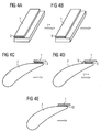
- FIGS. 4a to 4e A first exemplary embodiment of the method according to the invention is shown in FIGS. 4a to 4e.
- a trailing edge of a turbine blade is restored.
- a sheet 1 is shown, which is coated in a region which is to be applied to a component to be repaired with a layer 3 of solder.
- the solder is in powder form.
- the sheet 1, which may in particular be made of the base material of the turbine blade, has a thickness which corresponds to a typical for turbine blades exit edge wall thickness. That is, the sheet 1 is just thin enough to be adapted to the exit edge contour.
- the sheet 1 with the layer 3 of solder is subjected to a heat treatment (T + ). This will be on the sheet 1, a presintered layer 5 of solder is formed. In the heat treatment, the solder powder is reshaped so that a minimum cohesion of the solder powder particles is given and the solder powder compacts and solidifies.
- the sheet 1 with the pre-sintered layer 5 made of solder is shown in Fig. 4b.
- the sheet 1 with the pre-sintered layer 5 made of solder is placed on a turbine blade 7 as a component to be repaired. In this case, only that portion of the sheet 1 is brought into contact with the turbine blade 7, which has the pre-sintered layer 5 made of solder, as shown in Fig. 4c.
- the sheet 1 is fixed to the turbine blade by means of a spot welding process to form a few spot welds (not shown).
- a solder paste 9 is introduced such that between the edge region of the sheet 1 and the turbine blade 7 occurring gaps or gaps are filled.
- the turbine blade 7, on which the sheet 1 and the solder paste 9 are arranged, is shown in FIG. 4d.
- the turbine blade 7 and the sheet 1 are subjected to a soldering heat treatment (T ++ ) such that the sheet 1 is soldered to the turbine blade 7.
- T ++ soldering heat treatment
- the presintered layer 5 made of solder and the solder paste 9 are melted and solidified during subsequent cooling after the solder heat treatment to form a cohesive connection 10 between the turbine blade 7 and the sheet metal 1.
- the repaired, with the sheet 1 soldered turbine blade 7 is shown in Fig. 4e.
- a solder with, for example, boron is used as the melting point depressant.
- the heat treatment (T ++ ) therefore comprises three stages. In the In the first stage, the temperature is chosen so that the solder melts with the lowered melting point. The second stage is a diffusion heat treatment at a temperature below the solution annealing temperature. In this heat treatment step, the melting point depressant is expelled by diffusion. This is followed by the third stage of the soldering heat treatment at a temperature which is suitable for adjusting the structure of the base material in the region of the solder joint. Because of the now diffuse distribution of the melting point depressant due to the expulsion, the third stage can be carried out without remelting the solder.
- a low melting solder may also be used in conjunction with a flux on the higher melting base material. In this case, a one-step soldering heat treatment is sufficient.
- solder additives can reduce the mechanical properties as well as the oxidation resistance of the solder joint.
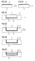
- FIGS. 5a to 5f A second embodiment of the method according to the invention is shown in FIGS. 5a to 5f.
- the wall 17 of a gas turbine component for example a running or vane or a cover member, is repaired or reinforced.
- a sheet 11 is shown having a layer 13 of solder.
- the solder is in powder form.
- the sheet 11 has a thickness comparable to the gas turbine wall to be repaired.
- the sheet 11 with the layer 13 of solder is subjected to a heat treatment (T + ). As a result, a pre-sintered layer 15 made of solder is formed on the metal sheet 11.
- the sheet 11 with the pre-sintered layer 15 made of solder is shown in Fig. 5b.
- the sheet 11 with the pre-sintered layer 15 of solder is placed in a recess 16 of the wall 17 of the component to be repaired, as shown in Fig. 5c, and fixed there with a few welds.
- a solder paste 19 is introduced such that between the wall 17 and the sheet 11 no gaps or gaps are present.
- the wall 17 and the sheet 11 of a soldering heat treatment (T ++ ) are subjected such that the sheet 11 is soldered to the wall 17 to form a cohesive connection 20.
- the repaired, soldered to the sheet 11 wall 17 is shown in Fig. 5e.
- FIG. 5f shows the repaired wall 17, in the depression 16 of which two sheets 11 are arranged stacked.
- the sheets 11 are connected to each other and to the wall 17 by a material connection 20.
Landscapes
- Engineering & Computer Science (AREA)
- Mechanical Engineering (AREA)
- General Engineering & Computer Science (AREA)
- Chemical & Material Sciences (AREA)
- Materials Engineering (AREA)
- Turbine Rotor Nozzle Sealing (AREA)
Priority Applications (1)
| Application Number | Priority Date | Filing Date | Title |
|---|---|---|---|
| EP06012072A EP1867423A1 (fr) | 2006-06-12 | 2006-06-12 | Procédé de réparation d'une pièce par brasage d'une tôle revêtue de brasure |
Applications Claiming Priority (1)
| Application Number | Priority Date | Filing Date | Title |
|---|---|---|---|
| EP06012072A EP1867423A1 (fr) | 2006-06-12 | 2006-06-12 | Procédé de réparation d'une pièce par brasage d'une tôle revêtue de brasure |
Publications (1)
| Publication Number | Publication Date |
|---|---|
| EP1867423A1 true EP1867423A1 (fr) | 2007-12-19 |
Family
ID=37398416
Family Applications (1)
| Application Number | Title | Priority Date | Filing Date |
|---|---|---|---|
| EP06012072A Withdrawn EP1867423A1 (fr) | 2006-06-12 | 2006-06-12 | Procédé de réparation d'une pièce par brasage d'une tôle revêtue de brasure |
Country Status (1)
| Country | Link |
|---|---|
| EP (1) | EP1867423A1 (fr) |
Cited By (11)
| Publication number | Priority date | Publication date | Assignee | Title |
|---|---|---|---|---|
| EP2108477A1 (fr) * | 2008-04-09 | 2009-10-14 | ALSTOM Technology Ltd | Procédé de réparation de composants à gaz chauds de turbine à gaz |
| EP2138258A1 (fr) * | 2008-06-23 | 2009-12-30 | Siemens Aktiengesellschaft | Procédé de soudage à profil de température à plusieurs niveaux |
| EP2347850A1 (fr) * | 2010-01-26 | 2011-07-27 | Rolls-Royce plc | Procédé de restauration d'un composant métallique |
| EP2837457A1 (fr) * | 2013-08-13 | 2015-02-18 | Siemens Aktiengesellschaft | Technique de brasage de composants de turbomachine |
| US8985955B2 (en) | 2010-07-28 | 2015-03-24 | General Electric Company | Turbine nozzle segment and method of repairing same |
| CN105081532A (zh) * | 2015-09-25 | 2015-11-25 | 东方电气集团东方汽轮机有限公司 | 一种汽轮机拂配式隔板叶栅焊接方法 |
| DE102014220164A1 (de) * | 2014-10-06 | 2016-04-07 | Siemens Aktiengesellschaft | Verfahren zum stoffschlüssigen Befestigen eines vorgesinterten Presslings an einem Bauteil |
| DE102014222054A1 (de) * | 2014-10-29 | 2016-05-04 | Siemens Aktiengesellschaft | Couponreparatur mittels Einsatz eines PSP-Elements und repariertes Bauteil |
| DE102015224988A1 (de) * | 2015-12-11 | 2017-06-14 | Rolls-Royce Deutschland Ltd & Co Kg | Verfahren zur Montage einer Brennkammer eines Gasturbinentriebwerks |
| CN111315960A (zh) * | 2017-11-13 | 2020-06-19 | 西门子股份公司 | 用于难焊接材料的制造方法 |
| EP3848142A1 (fr) * | 2020-01-08 | 2021-07-14 | General Electric Company | Pièce en superalliage et procédé de traitement |
Citations (7)
| Publication number | Priority date | Publication date | Assignee | Title |
|---|---|---|---|---|
| US5522134A (en) * | 1994-06-30 | 1996-06-04 | United Technologies Corporation | Turbine vane flow area restoration method |
| JPH09168927A (ja) * | 1995-12-19 | 1997-06-30 | Hitachi Ltd | ガスタービン用動翼,静翼の補修方法 |
| US5890274A (en) * | 1996-03-14 | 1999-04-06 | Societe Nationale D'etude Et De Construction De Moteurs D'aviation "Snecma", | Method of producing a coating layer on a localized area of a superalloy component |
| EP1065297A2 (fr) * | 1999-06-29 | 2001-01-03 | General Electric Company | Procédé pour fabriquer des revêtements résistants à l'usure et articles ainsi revêtus |
| EP1074331A1 (fr) * | 1999-08-02 | 2001-02-07 | General Electric Company | Procédé de réparation des pièces coulées en superalliage en utilisant un bouchon conique fixé par liason métallurgique |
| US6520401B1 (en) * | 2001-09-06 | 2003-02-18 | Sermatech International, Inc. | Diffusion bonding of gaps |
| EP1559868A2 (fr) * | 2004-01-29 | 2005-08-03 | United Technologies Corporation | Méthode de rétablissement des dimensions d'une aube et préformé pour son application |
-
2006
- 2006-06-12 EP EP06012072A patent/EP1867423A1/fr not_active Withdrawn
Patent Citations (7)
| Publication number | Priority date | Publication date | Assignee | Title |
|---|---|---|---|---|
| US5522134A (en) * | 1994-06-30 | 1996-06-04 | United Technologies Corporation | Turbine vane flow area restoration method |
| JPH09168927A (ja) * | 1995-12-19 | 1997-06-30 | Hitachi Ltd | ガスタービン用動翼,静翼の補修方法 |
| US5890274A (en) * | 1996-03-14 | 1999-04-06 | Societe Nationale D'etude Et De Construction De Moteurs D'aviation "Snecma", | Method of producing a coating layer on a localized area of a superalloy component |
| EP1065297A2 (fr) * | 1999-06-29 | 2001-01-03 | General Electric Company | Procédé pour fabriquer des revêtements résistants à l'usure et articles ainsi revêtus |
| EP1074331A1 (fr) * | 1999-08-02 | 2001-02-07 | General Electric Company | Procédé de réparation des pièces coulées en superalliage en utilisant un bouchon conique fixé par liason métallurgique |
| US6520401B1 (en) * | 2001-09-06 | 2003-02-18 | Sermatech International, Inc. | Diffusion bonding of gaps |
| EP1559868A2 (fr) * | 2004-01-29 | 2005-08-03 | United Technologies Corporation | Méthode de rétablissement des dimensions d'une aube et préformé pour son application |
Cited By (18)
| Publication number | Priority date | Publication date | Assignee | Title |
|---|---|---|---|---|
| EP2108477A1 (fr) * | 2008-04-09 | 2009-10-14 | ALSTOM Technology Ltd | Procédé de réparation de composants à gaz chauds de turbine à gaz |
| US8156649B2 (en) | 2008-04-09 | 2012-04-17 | Alstom Technology Ltd | Gas turbine hot gas component repair method |
| EP2138258A1 (fr) * | 2008-06-23 | 2009-12-30 | Siemens Aktiengesellschaft | Procédé de soudage à profil de température à plusieurs niveaux |
| US7832620B2 (en) | 2008-06-23 | 2010-11-16 | Siemens Aktiengesellschaft | Method for soldering with a multistep temperature profile |
| EP2347850A1 (fr) * | 2010-01-26 | 2011-07-27 | Rolls-Royce plc | Procédé de restauration d'un composant métallique |
| US8387853B2 (en) | 2010-01-26 | 2013-03-05 | Rolls-Royce, Plc | Method of restoring a metallic component |
| EP2412930A3 (fr) * | 2010-07-28 | 2018-01-24 | General Electric Company | Segment statorique de turbine et son procédé de réparation |
| US8985955B2 (en) | 2010-07-28 | 2015-03-24 | General Electric Company | Turbine nozzle segment and method of repairing same |
| EP2837457A1 (fr) * | 2013-08-13 | 2015-02-18 | Siemens Aktiengesellschaft | Technique de brasage de composants de turbomachine |
| DE102014220164A1 (de) * | 2014-10-06 | 2016-04-07 | Siemens Aktiengesellschaft | Verfahren zum stoffschlüssigen Befestigen eines vorgesinterten Presslings an einem Bauteil |
| DE102014222054A1 (de) * | 2014-10-29 | 2016-05-04 | Siemens Aktiengesellschaft | Couponreparatur mittels Einsatz eines PSP-Elements und repariertes Bauteil |
| CN105081532A (zh) * | 2015-09-25 | 2015-11-25 | 东方电气集团东方汽轮机有限公司 | 一种汽轮机拂配式隔板叶栅焊接方法 |
| DE102015224988A1 (de) * | 2015-12-11 | 2017-06-14 | Rolls-Royce Deutschland Ltd & Co Kg | Verfahren zur Montage einer Brennkammer eines Gasturbinentriebwerks |
| CN111315960A (zh) * | 2017-11-13 | 2020-06-19 | 西门子股份公司 | 用于难焊接材料的制造方法 |
| US11504774B2 (en) | 2017-11-13 | 2022-11-22 | Siemens Energy Global GmbH & Co. KG | Manufacturing method for hard-to-weld materials |
| CN111315960B (zh) * | 2017-11-13 | 2023-04-28 | 西门子能源全球两合公司 | 用于难焊接材料的制造方法 |
| EP3848142A1 (fr) * | 2020-01-08 | 2021-07-14 | General Electric Company | Pièce en superalliage et procédé de traitement |
| US11559847B2 (en) | 2020-01-08 | 2023-01-24 | General Electric Company | Superalloy part and method of processing |
Similar Documents
| Publication | Publication Date | Title |
|---|---|---|
| EP1910006B1 (fr) | Procede de reparation d'un composant comprenant une microstructure orientee par reglage, durant l'action thermique d'un faisceau d'electrons ou laser, d'un gradient de temperature | |
| EP1957685B1 (fr) | Procede de reparation de fissures dans des composants | |
| EP1954844B1 (fr) | Procede de reparation de fissures dans des composants et materiau d'apport destine au soudage de composants | |
| EP1867423A1 (fr) | Procédé de réparation d'une pièce par brasage d'une tôle revêtue de brasure | |
| EP2078579A1 (fr) | Procédé de soudage d'un composant et composant doté d'emplacements de soudure et de brasure | |
| EP1772228A1 (fr) | Procédé pour la réparation d'une pièce à microstructure orientée. | |
| EP1716965A1 (fr) | Brasure comprenant de la poudre d'apport métallique sous forme élémentaire | |
| EP1645653A1 (fr) | Revêtement protecteur | |
| EP1816316B1 (fr) | Procédé de réparation de composants | |
| WO2011113831A1 (fr) | Réparation d'arêtes de pièces structurales au moyen de préformes préfrittées en bandes (psp) et pièce structurale | |
| EP1764182A1 (fr) | Alliage de brasage à base de nickel et procédé de réparation d'une pièce | |
| WO2006040221A1 (fr) | Procede de production d'un systeme stratifie | |
| WO2008087084A1 (fr) | Mélange poudreux comprenant de la poudre en blocs, procédé d'utilisation du mélange poudreux et éléments de construction | |
| EP2230041B1 (fr) | Procédé de fabrication d'un trou | |
| EP1797985A1 (fr) | Procédé et dispositif de soudage | |
| WO2006069822A1 (fr) | Procede de creation d'un trou | |
| EP1867749A1 (fr) | Procédé de revêtement d'un matériau à une pièce | |
| EP1930115A1 (fr) | Fil, son utilisation et procédé de soudage | |
| WO2008052944A1 (fr) | Poudre de brasage composite constituée d'une âme et d'une enveloppe métallique, pour le brasage d'éléments de turbine | |
| EP1808572A1 (fr) | Procédé de soudage suivi d'un traitement de diffusion | |
| EP1797218A1 (fr) | Systeme de couches | |
| WO2006131404A1 (fr) | Procédé pour augmenter l'épaisseur de paroi d'un élément fait d'un alliage résistant aux hautes température | |
| EP1806419A1 (fr) | Alliage, couche protectrice pour proteger un élément structurel contre la corrosion et l'oxydation aux temperatures hautes, et élément structurel |
Legal Events
| Date | Code | Title | Description |
|---|---|---|---|
| PUAI | Public reference made under article 153(3) epc to a published international application that has entered the european phase |
Free format text: ORIGINAL CODE: 0009012 |
|
| AK | Designated contracting states |
Kind code of ref document: A1 Designated state(s): AT BE BG CH CY CZ DE DK EE ES FI FR GB GR HU IE IS IT LI LT LU LV MC NL PL PT RO SE SI SK TR |
|
| AX | Request for extension of the european patent |
Extension state: AL BA HR MK YU |
|
| AKX | Designation fees paid | ||
| STAA | Information on the status of an ep patent application or granted ep patent |
Free format text: STATUS: THE APPLICATION IS DEEMED TO BE WITHDRAWN |
|
| 18D | Application deemed to be withdrawn |
Effective date: 20080620 |
|
| REG | Reference to a national code |
Ref country code: DE Ref legal event code: 8566 |