EP1806419A1 - Alliage, couche protectrice pour proteger un élément structurel contre la corrosion et l'oxydation aux temperatures hautes, et élément structurel - Google Patents
Alliage, couche protectrice pour proteger un élément structurel contre la corrosion et l'oxydation aux temperatures hautes, et élément structurel Download PDFInfo
- Publication number
- EP1806419A1 EP1806419A1 EP06000405A EP06000405A EP1806419A1 EP 1806419 A1 EP1806419 A1 EP 1806419A1 EP 06000405 A EP06000405 A EP 06000405A EP 06000405 A EP06000405 A EP 06000405A EP 1806419 A1 EP1806419 A1 EP 1806419A1
- Authority
- EP
- European Patent Office
- Prior art keywords
- alloy
- component
- oxidation
- protective layer
- structural member
- Prior art date
- Legal status (The legal status is an assumption and is not a legal conclusion. Google has not performed a legal analysis and makes no representation as to the accuracy of the status listed.)
- Granted
Links
Images


Classifications
-
- C—CHEMISTRY; METALLURGY
- C22—METALLURGY; FERROUS OR NON-FERROUS ALLOYS; TREATMENT OF ALLOYS OR NON-FERROUS METALS
- C22C—ALLOYS
- C22C19/00—Alloys based on nickel or cobalt
- C22C19/07—Alloys based on nickel or cobalt based on cobalt
-
- B—PERFORMING OPERATIONS; TRANSPORTING
- B32—LAYERED PRODUCTS
- B32B—LAYERED PRODUCTS, i.e. PRODUCTS BUILT-UP OF STRATA OF FLAT OR NON-FLAT, e.g. CELLULAR OR HONEYCOMB, FORM
- B32B15/00—Layered products comprising a layer of metal
- B32B15/01—Layered products comprising a layer of metal all layers being exclusively metallic
-
- C—CHEMISTRY; METALLURGY
- C23—COATING METALLIC MATERIAL; COATING MATERIAL WITH METALLIC MATERIAL; CHEMICAL SURFACE TREATMENT; DIFFUSION TREATMENT OF METALLIC MATERIAL; COATING BY VACUUM EVAPORATION, BY SPUTTERING, BY ION IMPLANTATION OR BY CHEMICAL VAPOUR DEPOSITION, IN GENERAL; INHIBITING CORROSION OF METALLIC MATERIAL OR INCRUSTATION IN GENERAL
- C23C—COATING METALLIC MATERIAL; COATING MATERIAL WITH METALLIC MATERIAL; SURFACE TREATMENT OF METALLIC MATERIAL BY DIFFUSION INTO THE SURFACE, BY CHEMICAL CONVERSION OR SUBSTITUTION; COATING BY VACUUM EVAPORATION, BY SPUTTERING, BY ION IMPLANTATION OR BY CHEMICAL VAPOUR DEPOSITION, IN GENERAL
- C23C28/00—Coating for obtaining at least two superposed coatings either by methods not provided for in a single one of groups C23C2/00 - C23C26/00 or by combinations of methods provided for in subclasses C23C and C25C or C25D
- C23C28/30—Coatings combining at least one metallic layer and at least one inorganic non-metallic layer
- C23C28/32—Coatings combining at least one metallic layer and at least one inorganic non-metallic layer including at least one pure metallic layer
- C23C28/321—Coatings combining at least one metallic layer and at least one inorganic non-metallic layer including at least one pure metallic layer with at least one metal alloy layer
- C23C28/3215—Coatings combining at least one metallic layer and at least one inorganic non-metallic layer including at least one pure metallic layer with at least one metal alloy layer at least one MCrAlX layer
-
- C—CHEMISTRY; METALLURGY
- C23—COATING METALLIC MATERIAL; COATING MATERIAL WITH METALLIC MATERIAL; CHEMICAL SURFACE TREATMENT; DIFFUSION TREATMENT OF METALLIC MATERIAL; COATING BY VACUUM EVAPORATION, BY SPUTTERING, BY ION IMPLANTATION OR BY CHEMICAL VAPOUR DEPOSITION, IN GENERAL; INHIBITING CORROSION OF METALLIC MATERIAL OR INCRUSTATION IN GENERAL
- C23C—COATING METALLIC MATERIAL; COATING MATERIAL WITH METALLIC MATERIAL; SURFACE TREATMENT OF METALLIC MATERIAL BY DIFFUSION INTO THE SURFACE, BY CHEMICAL CONVERSION OR SUBSTITUTION; COATING BY VACUUM EVAPORATION, BY SPUTTERING, BY ION IMPLANTATION OR BY CHEMICAL VAPOUR DEPOSITION, IN GENERAL
- C23C28/00—Coating for obtaining at least two superposed coatings either by methods not provided for in a single one of groups C23C2/00 - C23C26/00 or by combinations of methods provided for in subclasses C23C and C25C or C25D
- C23C28/30—Coatings combining at least one metallic layer and at least one inorganic non-metallic layer
- C23C28/34—Coatings combining at least one metallic layer and at least one inorganic non-metallic layer including at least one inorganic non-metallic material layer, e.g. metal carbide, nitride, boride, silicide layer and their mixtures, enamels, phosphates and sulphates
- C23C28/345—Coatings combining at least one metallic layer and at least one inorganic non-metallic layer including at least one inorganic non-metallic material layer, e.g. metal carbide, nitride, boride, silicide layer and their mixtures, enamels, phosphates and sulphates with at least one oxide layer
- C23C28/3455—Coatings combining at least one metallic layer and at least one inorganic non-metallic layer including at least one inorganic non-metallic material layer, e.g. metal carbide, nitride, boride, silicide layer and their mixtures, enamels, phosphates and sulphates with at least one oxide layer with a refractory ceramic layer, e.g. refractory metal oxide, ZrO2, rare earth oxides or a thermal barrier system comprising at least one refractory oxide layer
-
- Y—GENERAL TAGGING OF NEW TECHNOLOGICAL DEVELOPMENTS; GENERAL TAGGING OF CROSS-SECTIONAL TECHNOLOGIES SPANNING OVER SEVERAL SECTIONS OF THE IPC; TECHNICAL SUBJECTS COVERED BY FORMER USPC CROSS-REFERENCE ART COLLECTIONS [XRACs] AND DIGESTS
- Y02—TECHNOLOGIES OR APPLICATIONS FOR MITIGATION OR ADAPTATION AGAINST CLIMATE CHANGE
- Y02T—CLIMATE CHANGE MITIGATION TECHNOLOGIES RELATED TO TRANSPORTATION
- Y02T50/00—Aeronautics or air transport
- Y02T50/60—Efficient propulsion technologies, e.g. for aircraft
Definitions
- the invention relates to an alloy according to claim 1, a protective layer for protecting a component against corrosion and / or oxidation at high temperatures according to claim 4 and a component according to claim 5.
- the invention relates to a protective layer for a component consisting of a nickel or cobalt base superalloy.
- MCrAlY Protective layers for metallic components intended to increase their corrosion resistance and / or oxidation resistance are known in the art in large numbers. Most of these protective layers are known by the collective name MCrAlY, where M represents at least one of the elements selected from the group consisting of iron, cobalt and nickel and further essential components chromium, aluminum and yttrium.
- inlet temperatures are important determinants of thermodynamic efficiencies achievable with gas turbines. Due to the use of specially developed alloys as base materials for components that are subject to high thermal loads such as guide vanes and rotor blades, in particular through the use of monocrystalline superalloys, inlet temperatures of well over 1000 ° C are possible. Meanwhile, the prior art allows inlet temperatures of 950 ° C and more in stationary gas turbines and 1100 ° C and more in gas turbines of aircraft engines.
- a protective layer must also have sufficient mechanical properties, not least in view of the mechanical interaction between the protective layer and the Base material, have.
- the protective layer must be sufficiently ductile in order to be able to follow any deformations of the base material and not to break, since in this way points of attack for oxidation and corrosion would be created.
- an object of the present invention to provide an alloy and a protective layer which has good high-temperature resistance in corrosion and oxidation, has good long-term stability and, in addition, a mechanical stress to be expected particularly in a gas turbine at a high temperature well adjusted.
- the object is achieved by an alloy according to claim 1 and a protective layer according to claim 4.
- Another object of the invention is to provide a component which has increased protection against corrosion and oxidation.
- a component according to claim 5 in particular a component of a gas turbine or steam turbine, which has a protective layer of the type described above for protection against corrosion and oxidation at high temperatures.
- the invention is u. a. based on the knowledge that the protective layer in the layer and in the transition region between the protective layer and the base material brittle precipitates shows.
- these brittle phases which form increasingly with time and temperature, lead to pronounced longitudinal cracks in the layer as well as in the interface layer base material with subsequent detachment of the layer.
- the brittleness of the precipitates increases as a result of the interaction with carbon which can diffuse from the base material into the layer or diffuses through the surface into the layer during a heat treatment in the furnace. By oxidation of these phases, the driving force for cracking is enhanced.
- the alloy can have further elements.
- the alloy consists only of cobalt, chromium and yttrium.
- the protective layer has good resistance to oxidation with good corrosion resistance and is also characterized by particularly good ductility properties, so that it is particularly qualified for use in a gas turbine with a further increase in the inlet temperature. During operation, embrittlement hardly occurs.
- the alloy of the protective layer 7 contains no nickel.
- the alloy does not contain aluminum.
- no silicon or rhenium must be alloyed.
- Cobalt-based alloys are particularly suitable for use in the combustion of contaminated heavy oil in a gas turbine or burner.
- the powders are applied for example by plasma spraying (APS, LPPS, VPS, ). Other methods are also conceivable (PVD, CVD, cold gas spraying).
- the thickness of the protective layer 7 on the component 1 is preferably dimensioned to a value of between about 100 ⁇ m and 300 ⁇ m.
- the protective layer 7 is advantageously applied to a substrate 4 made of a superalloy based on nickel or cobalt.
- substrate made of a superalloy based on nickel or cobalt.
- the following composition is suitable as substrate (data in wt%): 0.1% to 0.15% carbon 18% to 22% chrome 18% to 19% cobalt 0% to 2% tungsten 0% to 4% molybdenum 0% to 1.5% tantalum 0% to 1% niobium 1% to 3% aluminum 2% to 4% titanium 0% to 0.75% hafnium optionally small amounts of boron and / or zirconium, balance nickel.
- Compositions of this type are known as casting alloys under the designations GTD222, IN939, IN6203 and Udimet 500.
- the protective layer 7 is particularly suitable for protecting a component against corrosion and oxidation, while the component is acted upon by a flue gas at a material temperature of about 950 ° C., in aircraft turbines also by about 1100 ° C.
- the protective layer 7 is thus particularly qualified for protecting a component of a gas turbine 100, in particular a guide blade 120, blade 130 or other component, which is acted upon by hot gas before or in the turbine of the gas turbine.
- the protective layer 7 can be used as an overlay (protective layer is the outer layer) or as a bondcoat (protective layer is an intermediate layer).
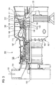
- FIG. 1 shows a layer system 1 as a component.
- the layer system 1 consists of a substrate 4.
- the substrate 4 may be metallic and / or ceramic.
- turbine components such as turbine runners 120 (FIG. 1) or vanes 130 (FIGS. 3, 5), combustor liners 155 (FIG. 4), and other housing parts of a steam or gas turbine 100 (FIG. 5)
- Substrate 4 made of a nickel-, cobalt- or iron-based superalloy.
- nickel-based superalloys are used.
- the protective layer 7 according to the invention is present.
- this protective layer 7 is applied by LPPS (low pressure plasma spraying). This can be used as outer layer (not shown) or intermediate layer (FIG. 1). In the latter case, a ceramic thermal barrier coating 10 is present on the protective layer 7.
- LPPS low pressure plasma spraying
- the protective layer 7 can be applied to newly manufactured components and remanufactured components from the refurbishment.
- Refurbishment means that after use, components 1 may be separated from layers (thermal barrier coating) and corrosion and oxidation products may be removed, for example by acid treatment (acid stripping). If necessary, cracks still have to be repaired. Thereafter, such a component can be coated again because the substrate 4 is very expensive.
- FIG. 3 shows by way of example a gas turbine 100 in a longitudinal partial section.
- the gas turbine 100 has inside a rotatably mounted about a rotation axis 102 rotor 103 with a shaft 101, which is also referred to as a turbine runner.
- a compressor 105 for example, a toroidal combustion chamber 110, in particular annular combustion chamber, with a plurality of coaxially arranged burners 107, a turbine 108 and the exhaust housing 109th
- the annular combustion chamber 110 communicates with an annular annular hot gas channel 111, for example.
- Each turbine stage 112 is formed, for example, from two blade rings. As seen in the direction of flow of a working medium 113, in the hot gas channel 111 of a row of guide vanes 115, a series 125 formed of rotor blades 120 follows.
- the guide vanes 130 are fastened to an inner housing 138 of a stator 143, whereas the moving blades 120 of a row 125 are attached to the rotor 103 by means of a turbine disk 133, for example. Coupled to the rotor 103 is a generator or work machine (not shown).
- air 105 is sucked in and compressed by the compressor 105 through the intake housing 104.
- the compressed air provided at the turbine-side end of the compressor 105 is supplied to the burners 107 where it is mixed with a fuel.
- the mixture is then burned to form the working fluid 113 in the combustion chamber 110.
- the working medium 113 flows along the hot gas channel 111 past the guide vanes 130 and the rotor blades 120.
- the working medium 113 expands in a pulse-transmitting manner, so that the rotor blades 120 drive the rotor 103 and drive the machine coupled to it.
- the components exposed to the hot working medium 113 are subject to thermal loads during operation of the gas turbine 100.
- the guide vanes 130 and rotor blades 120 of the first turbine stage 112, viewed in the flow direction of the working medium 113, are subjected to the greatest thermal stress in addition to the heat shield elements lining the annular combustion chamber 110. To withstand the prevailing temperatures, they can be cooled by means of a coolant.
- substrates of the components can have a directional structure, ie they are monocrystalline (SX structure) or have only longitudinal grains (DS structure).
- SX structure monocrystalline
- DS structure only longitudinal grains
- Such superalloys are for example from EP 1 204 776 B1 .
- EP 1 306 454 .
- the vane 130 has a guide vane foot (not shown here) facing the inner housing 138 of the turbine 108 and a vane head opposite the vane foot.
- the vane head is the rotor 103 facing and fixed to a mounting ring 140 of the stator 143.
- FIG. 4 shows a perspective view of a moving blade 120 or guide blade 130 of a turbomachine that extends along a longitudinal axis 121.
- the turbomachine may be a gas turbine of an aircraft or a power plant for power generation, a steam turbine or a compressor.
- the blade 120, 130 has along the longitudinal axis 121 consecutively a fastening region 400, a blade platform 403 adjacent thereto and an airfoil 406 and a blade tip 415.
- the blade 130 may have at its blade tip 415 another platform (not shown).
- a blade root 183 is formed, which serves for attachment of the blades 120, 130 to a shaft or a disc (not shown).
- the blade root 183 is designed, for example, as a hammer head. Other designs as Christmas tree or Schwalbenschwanzfuß are possible.
- the blade 120, 130 has a leading edge 409 and a trailing edge 412 for a medium flowing past the airfoil 406.
- the blade 120, 130 can be made by a casting process, also by directional solidification, by a forging process, by a milling process or combinations thereof.
- the blades 120, 130 may have coatings against corrosion or oxidation, e.g. M is at least one element of the group iron (Fe), cobalt (Co), nickel (Ni), X is an active element and stands for yttrium (Y) and / or silicon and / or at least one element of the rare ones Earth, or hafnium (Hf)).
- M is at least one element of the group iron (Fe), cobalt (Co), nickel (Ni)
- X is an active element and stands for yttrium (Y) and / or silicon and / or at least one element of the rare ones Earth, or hafnium (Hf)).
- Such alloys are known from the EP 0 486 489 B1 . EP 0 786 017 B1 . EP 0 412 397 B1 or EP 1 306 454 A1 which are to be part of this disclosure with regard to the chemical composition of the alloy.
- the density is preferably 95% of the theoretical density.
- thermal barrier coating which is preferably the outermost layer, and consists for example of Zr0 2 , Y 2 O 3 -ZrO 2 , ie it is not, partially or completely stabilized by yttria and / or calcium oxide and / or magnesium oxide.
- the thermal barrier coating covers the entire MCrAlX layer.
- suitable coating processes such as electron beam evaporation (EB-PVD)
- stalk-shaped grains are produced in the thermal barrier coating.
- Other coating methods are conceivable, for example atmospheric plasma spraying (APS), LPPS, VPS or CVD.
- the thermal barrier coating may have porous, micro- or macro-cracked grains for better thermal shock resistance.
- the thermal barrier coating is therefore preferably more porous than the MCrAlX layer.
- the blade 120, 130 may be hollow or solid. If the blade 120, 130 is to be cooled, it is hollow and may still film cooling holes 418 (indicated by dashed lines) on.
- FIG. 5 shows a combustion chamber 110 of the gas turbine 100.
- the combustion chamber 110 is configured, for example, as a so-called annular combustion chamber, in which a multiplicity of burners 107 arranged circumferentially around a rotation axis 102 open into a common combustion chamber space 154, which produce flames 156.
- the combustion chamber 110 is configured in its entirety as an annular structure, which is positioned around the axis of rotation 102 around.
- the combustion chamber 110 is designed for a comparatively high temperature of the working medium M of about 1000 ° C to 1600 ° C.
- the combustion chamber wall 153 is provided on its side facing the working medium M side with an inner lining formed from heat shield elements 155.
- the heat shield elements 155 are then, for example, hollow and possibly still have cooling holes (not shown) which open into the combustion chamber space 154.
- Each heat shield element 155 made of an alloy is equipped on the working medium side with a particularly heat-resistant protective layer (MCrAlX layer and / or ceramic coating) or is made of high-temperature-resistant material (solid ceramic blocks).
- M is at least one element of the group iron (Fe), cobalt (Co), nickel (Ni), X is an active element and stands for yttrium (Y) and / or silicon and / or at least one element of the rare earths, or hafnium (Hf).
- MCrAlX means: M is at least one element of the group iron (Fe), cobalt (Co), nickel (Ni), X is an active element and stands for yttrium (Y) and / or silicon and / or at least one element of the rare earths, or hafnium (Hf).
- Such alloys are known from the EP 0 486 489 B1 .
- a ceramic thermal barrier coating consists for example of ZrO 2 , Y 2 O-ZrO, ie it is not, partially or completely stabilized by yttria and / or calcium oxide and / or magnesium oxide.
- suitable coating processes such as electron beam evaporation (EB-PVD)
- stalk-shaped grains are produced in the thermal barrier coating.
- suitable coating methods are conceivable, for example atmospheric plasma spraying (APS), LPPS, VPS or CVD.
- the thermal barrier coating may have porous, micro- or macro-cracked grains for better thermal shock resistance.
- Refurbishment means that turbine blades 120, 130, heat shield elements 155 may need to be deprotected (e.g., by sandblasting) after use. This is followed by removal of the corrosion and / or oxidation layers or products. Optionally, cracks in the turbine blade 120, 130 or the heat shield element 155 are also repaired. This is followed by a re-coating of the turbine blades 120, 130, heat shield elements 155 and a renewed use of the turbine blades 120, 130 or the heat shield elements 155.
Priority Applications (2)
| Application Number | Priority Date | Filing Date | Title |
|---|---|---|---|
| DE502006004652T DE502006004652D1 (de) | 2006-01-10 | 2006-01-10 | Legierung, Schutzschicht zum Schutz eines Bauteils gegen Korrosion und Oxidation bei hohen Temperaturen und Bauteil |
| EP06000405A EP1806419B1 (fr) | 2006-01-10 | 2006-01-10 | Alliage, couche protectrice pour proteger un élément structurel contre la corrosion et l'oxydation aux temperatures hautes, et élément structurel |
Applications Claiming Priority (1)
| Application Number | Priority Date | Filing Date | Title |
|---|---|---|---|
| EP06000405A EP1806419B1 (fr) | 2006-01-10 | 2006-01-10 | Alliage, couche protectrice pour proteger un élément structurel contre la corrosion et l'oxydation aux temperatures hautes, et élément structurel |
Publications (2)
| Publication Number | Publication Date |
|---|---|
| EP1806419A1 true EP1806419A1 (fr) | 2007-07-11 |
| EP1806419B1 EP1806419B1 (fr) | 2009-08-26 |
Family
ID=36646088
Family Applications (1)
| Application Number | Title | Priority Date | Filing Date |
|---|---|---|---|
| EP06000405A Not-in-force EP1806419B1 (fr) | 2006-01-10 | 2006-01-10 | Alliage, couche protectrice pour proteger un élément structurel contre la corrosion et l'oxydation aux temperatures hautes, et élément structurel |
Country Status (2)
| Country | Link |
|---|---|
| EP (1) | EP1806419B1 (fr) |
| DE (1) | DE502006004652D1 (fr) |
Citations (14)
| Publication number | Priority date | Publication date | Assignee | Title |
|---|---|---|---|---|
| US3676085A (en) * | 1971-02-18 | 1972-07-11 | United Aircraft Corp | Cobalt base coating for the superalloys |
| WO1991001433A1 (fr) | 1989-07-25 | 1991-02-07 | Allied-Signal Inc. | Aube de turbine a double alliage |
| EP0412397A1 (fr) * | 1989-08-10 | 1991-02-13 | Siemens Aktiengesellschaft | Revêtement protecteur contenant du rhénium possédant une rÀ©sistance plus grande à la corrosion et l'oxydation |
| JPH03264153A (ja) * | 1990-03-13 | 1991-11-25 | Kawasaki Steel Corp | 冷却能に優れた熱交換体鋳物及びその製造方法 |
| EP0486489B1 (fr) | 1989-08-10 | 1994-11-02 | Siemens Aktiengesellschaft | Revetement anticorrosion resistant aux temperatures elevees, notamment pour elements de turbines a gaz |
| JPH08175828A (ja) * | 1994-12-26 | 1996-07-09 | Nippon Sheet Glass Co Ltd | フロートガラス製造用ロール |
| EP0892090A1 (fr) | 1997-02-24 | 1999-01-20 | Sulzer Innotec Ag | Procédé de fabrication de structure smonocristallines |
| EP0786017B1 (fr) | 1994-10-14 | 1999-03-24 | Siemens Aktiengesellschaft | Couche de protection de pieces contre la corrosion, l'oxydation et les contraintes thermiques excessives, et son procede de production |
| WO1999067435A1 (fr) | 1998-06-23 | 1999-12-29 | Siemens Aktiengesellschaft | Alliage a solidification directionnelle a resistance transversale a la rupture amelioree |
| US6024792A (en) | 1997-02-24 | 2000-02-15 | Sulzer Innotec Ag | Method for producing monocrystalline structures |
| WO2000044949A1 (fr) | 1999-01-28 | 2000-08-03 | Siemens Aktiengesellschaft | Superalliage a base de nickel presentant une bonne usinabilite |
| EP1306454A1 (fr) | 2001-10-24 | 2003-05-02 | Siemens Aktiengesellschaft | Revêtement protecteur contenant du rhénium pour la protection d'un élément contre l'oxydation et la corrosion aux températures élevées |
| EP1319729A1 (fr) | 2001-12-13 | 2003-06-18 | Siemens Aktiengesellschaft | Pièce résistante à des températures élevées réalisé en superalliage polycristallin ou monocristallin à base de nickel |
| EP1204776B1 (fr) | 1999-07-29 | 2004-06-02 | Siemens Aktiengesellschaft | Piece resistant a des temperatures elevees et son procede de production |
-
2006
- 2006-01-10 DE DE502006004652T patent/DE502006004652D1/de active Active
- 2006-01-10 EP EP06000405A patent/EP1806419B1/fr not_active Not-in-force
Patent Citations (15)
| Publication number | Priority date | Publication date | Assignee | Title |
|---|---|---|---|---|
| US3676085A (en) * | 1971-02-18 | 1972-07-11 | United Aircraft Corp | Cobalt base coating for the superalloys |
| WO1991001433A1 (fr) | 1989-07-25 | 1991-02-07 | Allied-Signal Inc. | Aube de turbine a double alliage |
| EP0412397B1 (fr) | 1989-08-10 | 1998-03-25 | Siemens Aktiengesellschaft | Revêtement protecteur contenant du rhénium possédant une résistance plus grande à la corrosion et l'oxydation |
| EP0412397A1 (fr) * | 1989-08-10 | 1991-02-13 | Siemens Aktiengesellschaft | Revêtement protecteur contenant du rhénium possédant une rÀ©sistance plus grande à la corrosion et l'oxydation |
| EP0486489B1 (fr) | 1989-08-10 | 1994-11-02 | Siemens Aktiengesellschaft | Revetement anticorrosion resistant aux temperatures elevees, notamment pour elements de turbines a gaz |
| JPH03264153A (ja) * | 1990-03-13 | 1991-11-25 | Kawasaki Steel Corp | 冷却能に優れた熱交換体鋳物及びその製造方法 |
| EP0786017B1 (fr) | 1994-10-14 | 1999-03-24 | Siemens Aktiengesellschaft | Couche de protection de pieces contre la corrosion, l'oxydation et les contraintes thermiques excessives, et son procede de production |
| JPH08175828A (ja) * | 1994-12-26 | 1996-07-09 | Nippon Sheet Glass Co Ltd | フロートガラス製造用ロール |
| EP0892090A1 (fr) | 1997-02-24 | 1999-01-20 | Sulzer Innotec Ag | Procédé de fabrication de structure smonocristallines |
| US6024792A (en) | 1997-02-24 | 2000-02-15 | Sulzer Innotec Ag | Method for producing monocrystalline structures |
| WO1999067435A1 (fr) | 1998-06-23 | 1999-12-29 | Siemens Aktiengesellschaft | Alliage a solidification directionnelle a resistance transversale a la rupture amelioree |
| WO2000044949A1 (fr) | 1999-01-28 | 2000-08-03 | Siemens Aktiengesellschaft | Superalliage a base de nickel presentant une bonne usinabilite |
| EP1204776B1 (fr) | 1999-07-29 | 2004-06-02 | Siemens Aktiengesellschaft | Piece resistant a des temperatures elevees et son procede de production |
| EP1306454A1 (fr) | 2001-10-24 | 2003-05-02 | Siemens Aktiengesellschaft | Revêtement protecteur contenant du rhénium pour la protection d'un élément contre l'oxydation et la corrosion aux températures élevées |
| EP1319729A1 (fr) | 2001-12-13 | 2003-06-18 | Siemens Aktiengesellschaft | Pièce résistante à des températures élevées réalisé en superalliage polycristallin ou monocristallin à base de nickel |
Non-Patent Citations (2)
| Title |
|---|
| PATENT ABSTRACTS OF JAPAN vol. 016, no. 077 (M - 1214) 25 February 1992 (1992-02-25) * |
| PATENT ABSTRACTS OF JAPAN vol. 1996, no. 11 29 November 1996 (1996-11-29) * |
Also Published As
| Publication number | Publication date |
|---|---|
| EP1806419B1 (fr) | 2009-08-26 |
| DE502006004652D1 (de) | 2009-10-08 |
Similar Documents
| Publication | Publication Date | Title |
|---|---|---|
| EP2458025B1 (fr) | Alliage, couche de protection et composant | |
| EP2612949B1 (fr) | Alliage, couche de protection et composant | |
| EP1793008A1 (fr) | Alliage, couche protectrice pour proteger un élément structurel contre la corrosion et l'oxydation aux temperatures hautes et élément structurel | |
| EP1798299B1 (fr) | Alliage, couche de protection et élément de construction | |
| EP1806418A1 (fr) | Alliage, couche protectrice pour proteger un élément structurel contre la corrosion et l'oxydation aux temperatures hautes et élément structurel | |
| EP1790743A1 (fr) | Alliage, couche de protection et composant | |
| EP1854898A1 (fr) | Alliage, couche de protection et composant | |
| EP2474413A1 (fr) | Alliage, couche de protection et composant | |
| EP2710167B1 (fr) | Alliage, couche de protection et composant | |
| EP2699713B1 (fr) | Système de revêtement d'une couche métallique à deux sous-couches | |
| EP2611949B1 (fr) | Alliage a base nickel, couche de protection et élément de construction | |
| EP2661370B1 (fr) | Alliage, couche protectrice et pièce | |
| EP1790746B1 (fr) | Alliage, couche de protection et composant | |
| EP2756107B1 (fr) | Alliage, couche de protection et composant | |
| EP1806419B1 (fr) | Alliage, couche protectrice pour proteger un élément structurel contre la corrosion et l'oxydation aux temperatures hautes, et élément structurel | |
| EP2345748A1 (fr) | Alliage, couche de protection et composant | |
| EP1818419A1 (fr) | Alliage, couche de protection et composant | |
| EP1798300A1 (fr) | Alliage, couche protectrice pour proteger un élément de construction contre la corrosion et/ou l'oxidation aux températures élévées et élément de construction | |
| EP2354260A1 (fr) | Alliage, couche de protection et composant |
Legal Events
| Date | Code | Title | Description |
|---|---|---|---|
| PUAI | Public reference made under article 153(3) epc to a published international application that has entered the european phase |
Free format text: ORIGINAL CODE: 0009012 |
|
| AK | Designated contracting states |
Kind code of ref document: A1 Designated state(s): AT BE BG CH CY CZ DE DK EE ES FI FR GB GR HU IE IS IT LI LT LU LV MC NL PL PT RO SE SI SK TR |
|
| AX | Request for extension of the european patent |
Extension state: AL BA HR MK YU |
|
| 17P | Request for examination filed |
Effective date: 20070720 |
|
| 17Q | First examination report despatched |
Effective date: 20070823 |
|
| AKX | Designation fees paid |
Designated state(s): CH DE GB IT LI |
|
| GRAP | Despatch of communication of intention to grant a patent |
Free format text: ORIGINAL CODE: EPIDOSNIGR1 |
|
| GRAS | Grant fee paid |
Free format text: ORIGINAL CODE: EPIDOSNIGR3 |
|
| GRAA | (expected) grant |
Free format text: ORIGINAL CODE: 0009210 |
|
| AK | Designated contracting states |
Kind code of ref document: B1 Designated state(s): CH DE GB IT LI |
|
| REG | Reference to a national code |
Ref country code: GB Ref legal event code: FG4D Free format text: NOT ENGLISH |
|
| REG | Reference to a national code |
Ref country code: CH Ref legal event code: EP Ref country code: CH Ref legal event code: NV Representative=s name: SIEMENS SCHWEIZ AG |
|
| REF | Corresponds to: |
Ref document number: 502006004652 Country of ref document: DE Date of ref document: 20091008 Kind code of ref document: P |
|
| PLBE | No opposition filed within time limit |
Free format text: ORIGINAL CODE: 0009261 |
|
| STAA | Information on the status of an ep patent application or granted ep patent |
Free format text: STATUS: NO OPPOSITION FILED WITHIN TIME LIMIT |
|
| 26N | No opposition filed |
Effective date: 20100527 |
|
| PGFP | Annual fee paid to national office [announced via postgrant information from national office to epo] |
Ref country code: DE Payment date: 20150320 Year of fee payment: 10 Ref country code: IT Payment date: 20150128 Year of fee payment: 10 |
|
| PGFP | Annual fee paid to national office [announced via postgrant information from national office to epo] |
Ref country code: GB Payment date: 20150114 Year of fee payment: 10 |
|
| PGFP | Annual fee paid to national office [announced via postgrant information from national office to epo] |
Ref country code: CH Payment date: 20150402 Year of fee payment: 10 |
|
| REG | Reference to a national code |
Ref country code: DE Ref legal event code: R119 Ref document number: 502006004652 Country of ref document: DE |
|
| REG | Reference to a national code |
Ref country code: CH Ref legal event code: PL |
|
| GBPC | Gb: european patent ceased through non-payment of renewal fee |
Effective date: 20160110 |
|
| PG25 | Lapsed in a contracting state [announced via postgrant information from national office to epo] |
Ref country code: LI Free format text: LAPSE BECAUSE OF NON-PAYMENT OF DUE FEES Effective date: 20160131 Ref country code: DE Free format text: LAPSE BECAUSE OF NON-PAYMENT OF DUE FEES Effective date: 20160802 Ref country code: GB Free format text: LAPSE BECAUSE OF NON-PAYMENT OF DUE FEES Effective date: 20160110 Ref country code: CH Free format text: LAPSE BECAUSE OF NON-PAYMENT OF DUE FEES Effective date: 20160131 |
|
| PG25 | Lapsed in a contracting state [announced via postgrant information from national office to epo] |
Ref country code: IT Free format text: LAPSE BECAUSE OF NON-PAYMENT OF DUE FEES Effective date: 20160110 |