EP1867404A1 - Closing method and closing machine - Google Patents
Closing method and closing machine Download PDFInfo
- Publication number
- EP1867404A1 EP1867404A1 EP06731215A EP06731215A EP1867404A1 EP 1867404 A1 EP1867404 A1 EP 1867404A1 EP 06731215 A EP06731215 A EP 06731215A EP 06731215 A EP06731215 A EP 06731215A EP 1867404 A1 EP1867404 A1 EP 1867404A1
- Authority
- EP
- European Patent Office
- Prior art keywords
- die
- work piece
- main body
- holder
- closing
- Prior art date
- Legal status (The legal status is an assumption and is not a legal conclusion. Google has not performed a legal analysis and makes no representation as to the accuracy of the status listed.)
- Granted
Links
Images



Classifications
-
- B—PERFORMING OPERATIONS; TRANSPORTING
- B21—MECHANICAL METAL-WORKING WITHOUT ESSENTIALLY REMOVING MATERIAL; PUNCHING METAL
- B21D—WORKING OR PROCESSING OF SHEET METAL OR METAL TUBES, RODS OR PROFILES WITHOUT ESSENTIALLY REMOVING MATERIAL; PUNCHING METAL
- B21D37/00—Tools as parts of machines covered by this subclass
- B21D37/16—Heating or cooling
-
- B—PERFORMING OPERATIONS; TRANSPORTING
- B21—MECHANICAL METAL-WORKING WITHOUT ESSENTIALLY REMOVING MATERIAL; PUNCHING METAL
- B21D—WORKING OR PROCESSING OF SHEET METAL OR METAL TUBES, RODS OR PROFILES WITHOUT ESSENTIALLY REMOVING MATERIAL; PUNCHING METAL
- B21D41/00—Application of procedures in order to alter the diameter of tube ends
- B21D41/04—Reducing; Closing
-
- B—PERFORMING OPERATIONS; TRANSPORTING
- B21—MECHANICAL METAL-WORKING WITHOUT ESSENTIALLY REMOVING MATERIAL; PUNCHING METAL
- B21K—MAKING FORGED OR PRESSED METAL PRODUCTS, e.g. HORSE-SHOES, RIVETS, BOLTS OR WHEELS
- B21K21/00—Making hollow articles not covered by a single preceding sub-group
- B21K21/12—Shaping end portions of hollow articles
- B21K21/14—Shaping end portions of hollow articles closed or substantially-closed ends, e.g. cartridge bottoms
Definitions
- This invention relates to an improvement in a closing method and a closing machine for closing an open end of a metal pipe material.
- a closing method a work piece constituted by a metal pipe material is rotated and a die is pressed against the work piece while the work piece is heated.
- the work piece undergoes plastic deformation as it gradually approaches the die.
- a closing machine used in the closing operation comprises an outer diameter chuck that holds an outer peripheral surface of the work piece, and a chuck spindle that drives the outer diameter chuck to rotate together with the work piece.
- the work piece is closed by pressing the rotating die against the work piece at an offset to the rotating work piece.
- JP2002-153930A The closing method and closing machine described above are disclosed in JP2002-153930A .
- the die In a conventional closing machine, the die is subjected to induction heating using a high-frequency heating device, and when the die reaches a high temperature of 300°C or more, the work piece is heated by pressing the die against the work piece. Thus, the work piece is closed.
- the die used in this conventional closing machine is formed with a steel material such as hot die steel or the like, for example, as the material that is subjected to induction heating by the high-frequency heating device, and therefore the wear resistance of the die is poorer than that of a die formed from cemented carbide, for example, leading to a reduction in the life of the die.
- a steel material such as hot die steel or the like, for example, as the material that is subjected to induction heating by the high-frequency heating device, and therefore the wear resistance of the die is poorer than that of a die formed from cemented carbide, for example, leading to a reduction in the life of the die.
- This invention provides a closing method for closing an open end of a work piece by pressing a die heated by a high frequency heating device against the work piece rotating about an axial center, characterized in that a die main body of the die, which contacts the work piece, is formed from a non-ferrous metal, whereas a holder surrounding the die main body is formed from a ferrous metal, and the holder is subjected to induction heating by the high-frequency heating device whereas the die main body is heated by heat transfer from the holder.
- This invention also provides a closing machine for closing an open end of a work piece by pressing a die heated by a high frequency heating device against the work piece rotating about an axial center, characterized in that the die comprises a die main body which contacts the work piece and a holder which surrounds the die main body, the die main body is formed from a non-ferrous metal, the holder is formed from a ferrous metal, and the holder is subjected to induction heating by the high-frequency heating device whereas the die main body is heated by heat transfer from the holder.
- the die comprises the die main body that contacts the work piece and the holder that surrounds the die main body, the die main body is formed from a non-ferrous metal, the holder is formed from a ferrous metal, and during a closing operation, the holder is subjected to induction heating by the high-frequency heating device whereas the die main body is heated by heat transfer from the holder.
- the die main body that is pressed against the work piece does not have to be subjected to induction heating through electromagnetic induction, and can be formed from a non-ferrous metal having high wear resistance.
- the life of the die can be greatly extended, and closing operations can be performed continuously over a long time period, enabling an improvement in production efficiency.
- FIGs. 1 to 3 show the overall constitution of a closing machine 1.
- three axes namely X, Y, and Z, are set orthogonal to each other. It is assumed that the X axis extends in a substantially horizontal lateral direction, the Y axis extends in a substantially horizontal front-rear direction, and the Z axis extends in a substantially vertical direction.
- the overall constitution of the closing machine 1 will now be described.
- Two chuck spindles 20 which drive a work piece 9 to rotate about its axial center, and a single die driving device 40 which drives a die 4, are provided in a central portion of the closing machine 1.
- the chuck spindles 20 perform a reciprocating motion in the X axis direction relative to a pedestal 3 via a chuck spindle moving device 30, to be described later, thereby moving alternately to the central portion of the closing machine 1 so as to bring the work piece 9 face to face with the die 4.
- the closing machine 1 performs a closing operation to close an open end of the work piece 9 by heating the work piece 9, which is constituted by a metal pipe material, using a high-frequency heating device 2, and pressing the die 4 against the rotating work piece 9 such that the work piece 9 undergoes plastic deformation.
- a thrust stopper moving device 60 which is positioned in front of the chuck spindle 20 for closing the work piece 9 so as to support an end portion of the work piece 9, and a core moving device 50, which moves a core 5 inside the work piece 9, are provided in the central portion of the closing machine 1.
- a pair of conveyors 18 and a work piece introducing device 10 are provided respectively on the left and right rear portions of the working machine 1.
- the work piece 9 is conveyed forward in the Y axis direction by each of the conveyors 18 and then conveyed forward in the Y axis direction by each of the work piece introducing devices 10, which are capable of movement in the Y axis direction.
- the work piece 9 is introduced into and gripped by the respective left and right chuck spindles 20.
- While one of the chuck spindles 20 is positioned in the central portion of the working machine 1 during a closing operation, the other chuck spindle 20 is positioned on either the left or right end portion of the closing machine 1 so as to receive the work piece 9 conveyed by the respective work piece introducing devices 10.
- a discharge device 17 for discharging the work piece 9 following the closing operation is provided at the front portion of the closing machine 1.
- the discharge device 17 causes a hand 13 gripping the work piece 9 to reciprocate in the X axis direction relative to the pedestal 3 such that the work piece 9, which is pushed out from the left and right chuck spindles 20, is conveyed to a conveyor 19 disposed on the right-hand front portion of the closing machine 1.
- the cooling device 70 is provided on the front right side of the closing machine 1.
- FIGs. 4A to 4G show a series of processes performed by the closing machine 1 to close the work piece 9. Each process of this closing method will now be described in sequence.
- an inner diameter chuck 8 of the work piece introducing device 10 is inserted into the work piece 9 such that the inner diameter chuck 8 grips the inner peripheral surface of the work piece 9.
- the work piece introducing device 10 causes the inner diameter chuck 8 to advance in the Y axis direction such that the work piece 9 is inserted into an outer diameter chuck 7 of the chuck spindle 20.
- the outer diameter chuck 7 grips the outer peripheral surface of the work piece 9.
- the work piece introducing device 10 causes the inner diameter chuck 8 to retreat in the Y axis direction such that the inner diameter chuck 8 is extracted from the work piece 9.
- the chuck spindle moving device 30 moves the chuck spindle 20 in the X axis direction until the work piece 9 is stopped in an operation position facing the die 4.
- the thrust stopper moving device 60 moves a thrust stopper 6 to a thrust operation reference position supporting a base end portion 9b of the work piece 9.
- the core moving device 50 introduces the core 5 into the inside of the work piece 9.
- the chuck spindle 20 drives the work piece 9 and the core 5 to rotate. Meanwhile, the die 4 is pressed against the heated work piece 9 by the die driving device 40. Thus, a tip end portion 9a of the work piece 9 is steadily reduced in diameter between the die 4 and the core 5 such that finally, the tip end portion 9a of the work piece 9 closes to form a bottom portion 9c.
- the die driving device 40 moves the die 4 rearward in the Y axis direction away from the work piece 9. Meanwhile, the thrust stopper moving device 60 moves the thrust stopper 6 forward in the Y axis direction away from the thrust operation reference position, and the core moving device 50 removes the core 5 from the inside of the work piece 9.
- the chuck spindle moving device 30 moves the chuck spindle 20 in the X axis direction such that the work piece 9 faces the inner diameter chuck 8, as shown in FIG. 4A.
- the work piece introducing device 10 causes the inner diameter chuck 8 to advance in the Y axis direction such that the base end portion 9b of the unclosed work piece 9 abuts against the bottom portion 9c of the closed work piece 9, and thus the closed work piece 9 is pushed out of the outer diameter chuck 7.
- the work piece introducing device 10 causes the inner diameter chuck 8 to advance in the Y axis direction, as shown in FIG. 4H, such that the inner diameter chuck 8 abuts against the bottom portion 9c of the closed work piece 9, and thus the closed work piece 9 is pushed out of the outer diameter chuck 7.
- the die 4 is constituted by a die main body 601 that contacts the work piece 9 and a holder 611 that surrounds the die main body 601, which are formed separately from each other.
- the die main body 601 is formed from cemented carbide serving as a non-ferrous metal.
- the cemented carbide is formed by blending and sintering metallic carbide powder and a non-ferrous metal powder such as tungsten, vanadium, titanium, tantalum, or cobalt, for example, and has high resistance to heat and wear.
- the die main body 601 has a disk-shaped outer form, and comprises a molding recessed portion 603 which comes into contact with the work piece 9 and is formed as a recessed indent in an end face 602 of the die main body 601 facing the work piece 9. During a closing operation, the tip end portion 9a of the work piece 9 is narrowed along the molding recessed portion 603.
- the holder 611 is formed from a steel material serving as a ferrous metal.
- the holder 611 is induction heated by the high-frequency heating device 2, and the die main body 601 is heated through heat transfer from the holder 611.
- Hot die steel for example, is used as the steel material.
- the holder 611 comprises a cylindrical die outer wall portion 615 that surrounds the die main body 601, a recessed portion 612 forming a recessed indent relative to an end face 616 of the die outer wall portion 615, a shaft portion 613 that is gripped by a chuck, not shown in the drawing, of the die driving device 40, and a hole 614 penetrating the shaft portion 613 in the Y axis direction.
- the die main body 601 is joined to the recessed portion 612 of the holder 611 by shrink-fitting. During the shrink-fitting operation, air existing between the recessed portion 612 and the die main body 601 escapes through the hole 614.
- An induction coil of the high-frequency heating device 2 is formed in a ring shape surrounding the die outer wall portion 615 of the holder 611 at a remove therefrom, and is provided concentrically with the die 4.
- the closing machine 1 is constituted as described above, and next, an action thereof will be described.
- the chuck spindle 20 drives the work piece 9 and the core 5 to rotate while the high-frequency heating device 2 subjects the die 4 to induction heating.
- the die driving device 40 then presses the die 4 against the work piece 9 while rotating the die 4 at an offset to the work piece 9 in order to close the work piece 9.
- the tip end portion 9a of the work piece 9 is gradually narrowed along the molding recessed portion 603 between the die 4 and the core 5 such that finally, the tip end portion 9a of the work piece 9 forms the closed bottom portion 9c.
- the high-frequency heating device 2 subjects the die 4 to induction heating through electromagnetic induction.
- a high-frequency current is caused to flow through the induction coil of the high-frequency heating device 2
- high-frequency magnetic flux is generated in the die 4
- a high current is induced in the steel holder 611 by the high-frequency magnetic flux.
- Joule heat is generated such that the holder 611 self-heats.
- the die main body 601 which is constituted by cemented carbide serving as a non-ferrous metal, is not subjected to induction heating through electromagnetic induction, but is heated by heat transfer from the holder 611.
- the holder 611 comprises the cylindrical die outer wall portion 615 surrounding the die main body 601, and the induction coil of the high-frequency heating device 2 is provided so as to surround the die outer wall portion 615.
- the high-frequency heating device 2 can subject the die outer wall portion 615 to effective induction heating through electromagnetic induction, and the die outer wall portion 615 can heat the die main body 601 effectively through heat transfer.
- the die main body 601 that is pressed against the work piece 9 is formed from cemented carbide, which has greater wear resistance than a steel material, and therefore the life of the die 4 can be extended approximately fourfold in comparison with a conventional die constituted by hot die steel. As a result, closing operations can be performed continuously over a long time period, enabling an improvement in production efficiency.
- the die main body 601 is harder than a steel material, and therefore wear on the work piece 9 during a closing operation can be reduced.
- non-ferrous metal forming the die main body 601 is not limited to cemented carbide, and a ceramic material or the like may be used.
- the closing method and closing machine of this invention are not limited to a closing operation such as that described above, for closing an open end of a work piece, and may be used in a spinning operation to reduce the diameter of a work piece by pressing a die against the rotating work piece.
Landscapes
- Engineering & Computer Science (AREA)
- Mechanical Engineering (AREA)
- Shaping Metal By Deep-Drawing, Or The Like (AREA)
- Forging (AREA)
- Mounting, Exchange, And Manufacturing Of Dies (AREA)
Abstract
Description
- This invention relates to an improvement in a closing method and a closing machine for closing an open end of a metal pipe material.
- In a closing method, a work piece constituted by a metal pipe material is rotated and a die is pressed against the work piece while the work piece is heated. Thus, the work piece undergoes plastic deformation as it gradually approaches the die.
- A closing machine used in the closing operation comprises an outer diameter chuck that holds an outer peripheral surface of the work piece, and a chuck spindle that drives the outer diameter chuck to rotate together with the work piece. The work piece is closed by pressing the rotating die against the work piece at an offset to the rotating work piece.
- The closing method and closing machine described above are disclosed in
JP2002-153930A - In a conventional closing machine, the die is subjected to induction heating using a high-frequency heating device, and when the die reaches a high temperature of 300°C or more, the work piece is heated by pressing the die against the work piece. Thus, the work piece is closed.
- However, the die used in this conventional closing machine is formed with a steel material such as hot die steel or the like, for example, as the material that is subjected to induction heating by the high-frequency heating device, and therefore the wear resistance of the die is poorer than that of a die formed from cemented carbide, for example, leading to a reduction in the life of the die.
- It is therefore an object of this invention to provide a closing method and a closing machine in which the life of a die is extended.
- This invention provides a closing method for closing an open end of a work piece by pressing a die heated by a high frequency heating device against the work piece rotating about an axial center, characterized in that a die main body of the die, which contacts the work piece, is formed from a non-ferrous metal, whereas a holder surrounding the die main body is formed from a ferrous metal, and the holder is subjected to induction heating by the high-frequency heating device whereas the die main body is heated by heat transfer from the holder.
- This invention also provides a closing machine for closing an open end of a work piece by pressing a die heated by a high frequency heating device against the work piece rotating about an axial center, characterized in that the die comprises a die main body which contacts the work piece and a holder which surrounds the die main body, the die main body is formed from a non-ferrous metal, the holder is formed from a ferrous metal, and the holder is subjected to induction heating by the high-frequency heating device whereas the die main body is heated by heat transfer from the holder.
- According to this invention, the die comprises the die main body that contacts the work piece and the holder that surrounds the die main body, the die main body is formed from a non-ferrous metal, the holder is formed from a ferrous metal, and during a closing operation, the holder is subjected to induction heating by the high-frequency heating device whereas the die main body is heated by heat transfer from the holder. Hence, the die main body that is pressed against the work piece does not have to be subjected to induction heating through electromagnetic induction, and can be formed from a non-ferrous metal having high wear resistance. As a result, the life of the die can be greatly extended, and closing operations can be performed continuously over a long time period, enabling an improvement in production efficiency.
-
- FIG. 1 is a side view of a closing machine, illustrating an embodiment of this invention.
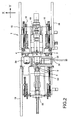
- FIG. 2 is a plan view of the closing machine.
- FIG. 3 is a front view of the closing machine.
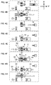
- FIGs. 4A - 4H are views showing closing processes.
- FIG. 5 is a sectional view of a die.
- This invention will now be described in further detail with reference to the attached drawings.
- FIGs. 1 to 3 show the overall constitution of a
closing machine 1. In FIGs. 1 to 3, three axes, namely X, Y, and Z, are set orthogonal to each other. It is assumed that the X axis extends in a substantially horizontal lateral direction, the Y axis extends in a substantially horizontal front-rear direction, and the Z axis extends in a substantially vertical direction. The overall constitution of theclosing machine 1 will now be described. - Two chuck spindles 20 which drive a
work piece 9 to rotate about its axial center, and a singledie driving device 40 which drives adie 4, are provided in a central portion of theclosing machine 1. Thechuck spindles 20 perform a reciprocating motion in the X axis direction relative to apedestal 3 via a chuckspindle moving device 30, to be described later, thereby moving alternately to the central portion of theclosing machine 1 so as to bring thework piece 9 face to face with thedie 4. - The
closing machine 1 performs a closing operation to close an open end of thework piece 9 by heating thework piece 9, which is constituted by a metal pipe material, using a high-frequency heating device 2, and pressing thedie 4 against therotating work piece 9 such that thework piece 9 undergoes plastic deformation. - A thrust
stopper moving device 60, which is positioned in front of thechuck spindle 20 for closing thework piece 9 so as to support an end portion of thework piece 9, and acore moving device 50, which moves acore 5 inside thework piece 9, are provided in the central portion of theclosing machine 1. - A pair of
conveyors 18 and a workpiece introducing device 10 are provided respectively on the left and right rear portions of theworking machine 1. Thework piece 9 is conveyed forward in the Y axis direction by each of theconveyors 18 and then conveyed forward in the Y axis direction by each of the workpiece introducing devices 10, which are capable of movement in the Y axis direction. Thus, thework piece 9 is introduced into and gripped by the respective left and right chuck spindles 20. - While one of the
chuck spindles 20 is positioned in the central portion of theworking machine 1 during a closing operation, theother chuck spindle 20 is positioned on either the left or right end portion of theclosing machine 1 so as to receive thework piece 9 conveyed by the respective workpiece introducing devices 10. - A
discharge device 17 for discharging thework piece 9 following the closing operation is provided at the front portion of theclosing machine 1. Thedischarge device 17 causes ahand 13 gripping thework piece 9 to reciprocate in the X axis direction relative to thepedestal 3 such that thework piece 9, which is pushed out from the left andright chuck spindles 20, is conveyed to aconveyor 19 disposed on the right-hand front portion of theclosing machine 1. - Once the closing operation is complete, the
work piece 9, which is at a high temperature of 1000°C or more, is conveyed to a cooling device 70 (see FIG. 3) by theconveyor 19 and cooled by thecooling device 70. Thecooling device 70 is provided on the front right side of theclosing machine 1. - FIGs. 4A to 4G show a series of processes performed by the
closing machine 1 to close thework piece 9. Each process of this closing method will now be described in sequence. - Referring to FIG. 4A, an
inner diameter chuck 8 of the workpiece introducing device 10 is inserted into thework piece 9 such that the inner diameter chuck 8 grips the inner peripheral surface of thework piece 9. - Referring to FIG. 4B, the work
piece introducing device 10 causes theinner diameter chuck 8 to advance in the Y axis direction such that thework piece 9 is inserted into anouter diameter chuck 7 of thechuck spindle 20. Thus, the outer diameter chuck 7 grips the outer peripheral surface of thework piece 9. - Referring to FIG. 4C, the work
piece introducing device 10 causes theinner diameter chuck 8 to retreat in the Y axis direction such that theinner diameter chuck 8 is extracted from thework piece 9. Next, the chuckspindle moving device 30 moves thechuck spindle 20 in the X axis direction until thework piece 9 is stopped in an operation position facing thedie 4. - Referring to FIG. 4D, the thrust
stopper moving device 60 moves athrust stopper 6 to a thrust operation reference position supporting abase end portion 9b of thework piece 9. - Referring to FIG. 4E, the
core moving device 50 introduces thecore 5 into the inside of thework piece 9. - Referring to FIG. 4F, the
chuck spindle 20 drives thework piece 9 and thecore 5 to rotate. Meanwhile, the die 4 is pressed against theheated work piece 9 by thedie driving device 40. Thus, atip end portion 9a of thework piece 9 is steadily reduced in diameter between thedie 4 and thecore 5 such that finally, thetip end portion 9a of thework piece 9 closes to form abottom portion 9c. - Referring to FIG. 4G, the die
driving device 40 moves the die 4 rearward in the Y axis direction away from thework piece 9. Meanwhile, the thrust stopper movingdevice 60 moves the thrust stopper 6 forward in the Y axis direction away from the thrust operation reference position, and thecore moving device 50 removes thecore 5 from the inside of thework piece 9. - To close another
work piece 9 thereafter, the chuckspindle moving device 30 moves thechuck spindle 20 in the X axis direction such that thework piece 9 faces theinner diameter chuck 8, as shown in FIG. 4A. Then, as shown in FIG, 4B, the workpiece introducing device 10 causes theinner diameter chuck 8 to advance in the Y axis direction such that thebase end portion 9b of theunclosed work piece 9 abuts against thebottom portion 9c of theclosed work piece 9, and thus theclosed work piece 9 is pushed out of theouter diameter chuck 7. - To terminate the closing operation of the
work piece 9, the workpiece introducing device 10 causes theinner diameter chuck 8 to advance in the Y axis direction, as shown in FIG. 4H, such that theinner diameter chuck 8 abuts against thebottom portion 9c of theclosed work piece 9, and thus theclosed work piece 9 is pushed out of theouter diameter chuck 7. - The overall constitution of the
closing machine 1 was described above. - Next, the constitution of the
die 4 shown in FIG. 5 will be described. - The
die 4 is constituted by a diemain body 601 that contacts thework piece 9 and aholder 611 that surrounds the diemain body 601, which are formed separately from each other. - The die
main body 601 is formed from cemented carbide serving as a non-ferrous metal. The cemented carbide is formed by blending and sintering metallic carbide powder and a non-ferrous metal powder such as tungsten, vanadium, titanium, tantalum, or cobalt, for example, and has high resistance to heat and wear. - The die
main body 601 has a disk-shaped outer form, and comprises a molding recessedportion 603 which comes into contact with thework piece 9 and is formed as a recessed indent in anend face 602 of the diemain body 601 facing thework piece 9. During a closing operation, thetip end portion 9a of thework piece 9 is narrowed along the molding recessedportion 603. - The
holder 611 is formed from a steel material serving as a ferrous metal. Theholder 611 is induction heated by the high-frequency heating device 2, and the diemain body 601 is heated through heat transfer from theholder 611. Hot die steel, for example, is used as the steel material. - The
holder 611 comprises a cylindrical dieouter wall portion 615 that surrounds the diemain body 601, a recessedportion 612 forming a recessed indent relative to anend face 616 of the dieouter wall portion 615, ashaft portion 613 that is gripped by a chuck, not shown in the drawing, of thedie driving device 40, and ahole 614 penetrating theshaft portion 613 in the Y axis direction. - The die
main body 601 is joined to the recessedportion 612 of theholder 611 by shrink-fitting. During the shrink-fitting operation, air existing between the recessedportion 612 and the diemain body 601 escapes through thehole 614. - An induction coil of the high-
frequency heating device 2 is formed in a ring shape surrounding the dieouter wall portion 615 of theholder 611 at a remove therefrom, and is provided concentrically with thedie 4. - The closing
machine 1 is constituted as described above, and next, an action thereof will be described. - In the
closing machine 1, thechuck spindle 20 drives thework piece 9 and thecore 5 to rotate while the high-frequency heating device 2 subjects thedie 4 to induction heating. Thedie driving device 40 then presses thedie 4 against thework piece 9 while rotating thedie 4 at an offset to thework piece 9 in order to close thework piece 9. Thus, as shown in FIG. 4F, thetip end portion 9a of thework piece 9 is gradually narrowed along the molding recessedportion 603 between thedie 4 and thecore 5 such that finally, thetip end portion 9a of thework piece 9 forms theclosed bottom portion 9c. - During this closing operation, the high-
frequency heating device 2 subjects thedie 4 to induction heating through electromagnetic induction. When a high-frequency current is caused to flow through the induction coil of the high-frequency heating device 2, high-frequency magnetic flux is generated in thedie 4, and a high current is induced in thesteel holder 611 by the high-frequency magnetic flux. Thus, Joule heat is generated such that theholder 611 self-heats. Meanwhile, the diemain body 601, which is constituted by cemented carbide serving as a non-ferrous metal, is not subjected to induction heating through electromagnetic induction, but is heated by heat transfer from theholder 611. - The
holder 611 comprises the cylindrical dieouter wall portion 615 surrounding the diemain body 601, and the induction coil of the high-frequency heating device 2 is provided so as to surround the dieouter wall portion 615. Thus, the high-frequency heating device 2 can subject the dieouter wall portion 615 to effective induction heating through electromagnetic induction, and the dieouter wall portion 615 can heat the diemain body 601 effectively through heat transfer. - The die
main body 601 that is pressed against thework piece 9 is formed from cemented carbide, which has greater wear resistance than a steel material, and therefore the life of thedie 4 can be extended approximately fourfold in comparison with a conventional die constituted by hot die steel. As a result, closing operations can be performed continuously over a long time period, enabling an improvement in production efficiency. - Moreover, the die
main body 601 is harder than a steel material, and therefore wear on thework piece 9 during a closing operation can be reduced. - Further, the non-ferrous metal forming the die
main body 601 is not limited to cemented carbide, and a ceramic material or the like may be used. - The closing method and closing machine of this invention are not limited to a closing operation such as that described above, for closing an open end of a work piece, and may be used in a spinning operation to reduce the diameter of a work piece by pressing a die against the rotating work piece.
Claims (4)
- A closing method for closing an open end of a work piece (9) by pressing a die (4) heated by a high frequency heating device (2) against the work piece (9) rotating about an axial center, characterized in that:a die main body (601) of the die (4), which contacts the work piece (9), is formed from a non-ferrous metal, whereas a holder (611) surrounding the die main body (601) is formed from a ferrous metal; andthe holder (611) is subjected to induction heating by the high-frequency heating device (2) whereas the die main body (60 1) is heated by heat transfer from the holder (611).
- A closing machine (1) for closing an open end of a work piece (9) by pressing a die (4) heated by a high frequency heating device (2) against the work piece (9) rotating about an axial center, characterized in that:the die (4) comprises a die main body (601) which contacts the work piece (9), and a holder (611) which surrounds the die main body (601);the die main body (601) is formed from a non-ferrous metal;the holder (611) is formed from a ferrous metal; andthe holder (611) is subjected to induction heating by the high-frequency heating device (2) whereas the die main body (601) is heated by heat transfer from the holder (611).
- The closing machine (1) as defined in Claim 2, characterized in that the die main body (601) is formed from a cemented carbide.
- The closing machine (1) as defined in Claim 2, characterized in that the holder (611) comprises a cylindrical die outer wall portion (615) which surrounds the die main body (601), and an induction coil of the high-frequency heating device (2) is provided so as to surround the die outer wall portion (615).
Applications Claiming Priority (2)
| Application Number | Priority Date | Filing Date | Title |
|---|---|---|---|
| JP2005101786A JP4649255B2 (en) | 2005-03-31 | 2005-03-31 | Closing processing method and closing processing machine |
| PCT/JP2006/307267 WO2006107088A1 (en) | 2005-03-31 | 2006-03-30 | Closing method and closing machine |
Publications (3)
| Publication Number | Publication Date |
|---|---|
| EP1867404A1 true EP1867404A1 (en) | 2007-12-19 |
| EP1867404A4 EP1867404A4 (en) | 2012-03-07 |
| EP1867404B1 EP1867404B1 (en) | 2013-05-08 |
Family
ID=37073621
Family Applications (1)
| Application Number | Title | Priority Date | Filing Date |
|---|---|---|---|
| EP06731215.7A Expired - Lifetime EP1867404B1 (en) | 2005-03-31 | 2006-03-30 | Closing method and closing machine |
Country Status (5)
| Country | Link |
|---|---|
| US (1) | US20090272170A1 (en) |
| EP (1) | EP1867404B1 (en) |
| JP (1) | JP4649255B2 (en) |
| ES (1) | ES2417017T3 (en) |
| WO (1) | WO2006107088A1 (en) |
Cited By (2)
| Publication number | Priority date | Publication date | Assignee | Title |
|---|---|---|---|---|
| CN105234545A (en) * | 2015-11-10 | 2016-01-13 | 长沙固鑫机械设备有限公司 | Equipment and method for automatically blocking end opening of metal round pipe |
| CN105344856A (en) * | 2015-12-18 | 2016-02-24 | 哈尔滨锅炉厂有限责任公司 | Device and method for spinning and sealing tube |
Families Citing this family (7)
| Publication number | Priority date | Publication date | Assignee | Title |
|---|---|---|---|---|
| JP5139683B2 (en) * | 2007-01-17 | 2013-02-06 | カヤバ工業株式会社 | Closing processing apparatus and closing processing method |
| JP2012139724A (en) * | 2010-12-17 | 2012-07-26 | Univ Of Yamanashi | Progressive press-working apparatus |
| CN102688950B (en) * | 2011-03-23 | 2014-06-11 | 哈尔滨建成集团有限公司 | Integral forming process of steel cylinders |
| CN103394864B (en) * | 2013-08-03 | 2016-01-20 | 山东丝绸纺织职业学院 | Stainless steel metal channel closure technique and sealing workpiece |
| CN113492179B (en) * | 2021-08-13 | 2024-11-08 | 莱州鸿源台钳制造有限公司 | A shrinking device |
| CN116174590B (en) * | 2022-12-29 | 2026-03-17 | 北京航星机器制造有限公司 | A method and apparatus for high-frequency coil heating and forming of titanium alloy ring-rib parts. |
| CN117428427A (en) * | 2023-10-30 | 2024-01-23 | 伊诺新能源(浙江)有限公司 | A kind of liner manufacturing technology |
Family Cites Families (22)
| Publication number | Priority date | Publication date | Assignee | Title |
|---|---|---|---|---|
| US2434737A (en) * | 1943-09-28 | 1948-01-20 | Production Plating Works Inc | Machine for closing tube ends |
| US2524420A (en) * | 1947-09-20 | 1950-10-03 | Earle A Blampin | Spinning-in the ends of tubes |
| US2513739A (en) * | 1949-03-15 | 1950-07-04 | Cosmopolitan Wares Inc | Method and apparatus for forming metallic bodies |
| US2647979A (en) * | 1952-06-27 | 1953-08-04 | Massey Harris Co Ltd | Method and apparatus for forming large upsets |
| US3050613A (en) * | 1959-09-23 | 1962-08-21 | Sylvania Electric Prod | Apparatus and method for bonding tubular elements |
| IT649693A (en) * | 1961-05-30 | |||
| US3475786A (en) * | 1966-12-30 | 1969-11-04 | Medical Supply Co | Tube closing machine |
| US3594894A (en) * | 1968-11-20 | 1971-07-27 | Gen Fire Extinguisher Corp | Method of forming cartridges |
| US3882594A (en) * | 1972-02-22 | 1975-05-13 | Servco Co | Method of forming a hard facing on the body of a tool |
| US4627665A (en) * | 1985-04-04 | 1986-12-09 | Ss Indus. | Cold-headed and roll-formed pick type cutter body with carbide insert |
| US5093039A (en) * | 1989-01-30 | 1992-03-03 | Kazunori Kijima | Highly pure sintered carbide with high electric conductivity and process of producing the same |
| WO1995016525A1 (en) * | 1993-12-16 | 1995-06-22 | Kawasaki Steel Corporation | Method of and apparatus for joining metal pieces |
| DE4431517C2 (en) * | 1994-08-11 | 1997-11-13 | Manfred Klever | Method of forming end pieces on tubular metal workpieces |
| DE19714753B4 (en) * | 1997-04-10 | 2012-01-05 | GFU-Gesellschaft für Umformung und Maschinenbau GmbH | A method of forming a closed container bottom on a tubular metal workpiece |
| US6742236B1 (en) * | 1999-09-20 | 2004-06-01 | Smith & Nephew, Inc. | Making closed end tubes for surgical instruments |
| BE1013336A3 (en) * | 2000-03-01 | 2001-12-04 | Diamant Boart Nv | Tubular drill. |
| JP2002153930A (en) * | 2000-09-06 | 2002-05-28 | Toyota Motor Corp | Hollow member, method of manufacturing the same, fluid circulation system using the hollow member, and apparatus for forming hollow material |
| JP4851646B2 (en) * | 2000-12-26 | 2012-01-11 | カヤバ工業株式会社 | Production method of strut type outer shell unit |
| ES2346512T3 (en) * | 2000-12-26 | 2010-10-18 | Kayaba Industry Co., Ltd. | METHODS OF MANUFACTURE OF AN OUTDOOR SHIRT UNIT. |
| JP2002295569A (en) * | 2001-03-28 | 2002-10-09 | Kayaba Ind Co Ltd | Strut type outer shell unit |
| JP2003200241A (en) * | 2001-12-27 | 2003-07-15 | Tokico Ltd | Pipe end closing method and apparatus |
| JP4547702B2 (en) * | 2004-05-31 | 2010-09-22 | 日立オートモティブシステムズ株式会社 | Bottomed tube and manufacturing method thereof |
-
2005
- 2005-03-31 JP JP2005101786A patent/JP4649255B2/en not_active Expired - Fee Related
-
2006
- 2006-03-30 EP EP06731215.7A patent/EP1867404B1/en not_active Expired - Lifetime
- 2006-03-30 WO PCT/JP2006/307267 patent/WO2006107088A1/en not_active Ceased
- 2006-03-30 ES ES06731215T patent/ES2417017T3/en not_active Expired - Lifetime
- 2006-03-30 US US11/887,137 patent/US20090272170A1/en not_active Abandoned
Cited By (3)
| Publication number | Priority date | Publication date | Assignee | Title |
|---|---|---|---|---|
| CN105234545A (en) * | 2015-11-10 | 2016-01-13 | 长沙固鑫机械设备有限公司 | Equipment and method for automatically blocking end opening of metal round pipe |
| CN105344856A (en) * | 2015-12-18 | 2016-02-24 | 哈尔滨锅炉厂有限责任公司 | Device and method for spinning and sealing tube |
| CN105344856B (en) * | 2015-12-18 | 2016-10-12 | 哈尔滨锅炉厂有限责任公司 | A kind of device of pipe rotation press closing |
Also Published As
| Publication number | Publication date |
|---|---|
| EP1867404A4 (en) | 2012-03-07 |
| ES2417017T3 (en) | 2013-08-05 |
| JP2006281236A (en) | 2006-10-19 |
| EP1867404B1 (en) | 2013-05-08 |
| US20090272170A1 (en) | 2009-11-05 |
| WO2006107088A1 (en) | 2006-10-12 |
| JP4649255B2 (en) | 2011-03-09 |
Similar Documents
| Publication | Publication Date | Title |
|---|---|---|
| US6899265B2 (en) | Electric joining method and apparatus and a joined unit of members | |
| EP1867404B1 (en) | Closing method and closing machine | |
| CN113020514A (en) | Deep blind hole shell pulse current auxiliary local upsetting continuous forming method and device | |
| CN105964721B (en) | A kind of preparation method of molybdenum and molybdenum alloy tubing | |
| JP4227285B2 (en) | Manufacturing method and manufacturing system of aluminum alloy preform body | |
| EP1870175B1 (en) | Closing method and closing machine | |
| EP1867407B1 (en) | Closing method and closing machine | |
| CN105828986A (en) | A method for manufacturing a cladded component | |
| CN209664223U (en) | The manufacturing device of rack bar | |
| EP1870177B1 (en) | Closing method and closing machine | |
| EP1867405B1 (en) | Closing method and closing machine | |
| KR101468968B1 (en) | Hot-extract apparatus for hollow inconel-billet by centrifugal casting | |
| JP2004122168A (en) | Manufacturing method and manufacturing apparatus for hollow forged products | |
| US20090126437A1 (en) | Closing Method and Closing Machine | |
| JP4349602B2 (en) | Shrink fit tempering device for machine tool | |
| CN218710687U (en) | Novel tooling frame for heat treatment of powder high-temperature alloy workpieces | |
| JP2003053473A (en) | Manufacturing method of substantially cylindrical forgings | |
| JPH04342887A (en) | Scroll molding mold and its processing method | |
| JP3098172U (en) | Mold for pharmaceutical tablets | |
| KR20260014119A (en) | Method for processing dual phased hardmetal tool using thermal expansion | |
| JPH02187232A (en) | Continuous forging method and device for turbine blades | |
| JPH0685958B2 (en) | High melting point metal pipe manufacturing method and apparatus | |
| JP2004017137A (en) | Method for manufacturing hollow needle | |
| JP2003136139A (en) | Deformation correction method for cylindrical water-cooled crucible | |
| JPH0282487A (en) | High frequency heater |
Legal Events
| Date | Code | Title | Description |
|---|---|---|---|
| PUAI | Public reference made under article 153(3) epc to a published international application that has entered the european phase |
Free format text: ORIGINAL CODE: 0009012 |
|
| 17P | Request for examination filed |
Effective date: 20071017 |
|
| AK | Designated contracting states |
Kind code of ref document: A1 Designated state(s): CZ DE ES FR GB |
|
| DAX | Request for extension of the european patent (deleted) | ||
| RBV | Designated contracting states (corrected) |
Designated state(s): CZ DE ES FR GB |
|
| A4 | Supplementary search report drawn up and despatched |
Effective date: 20120202 |
|
| RIC1 | Information provided on ipc code assigned before grant |
Ipc: B21D 37/16 20060101ALI20120127BHEP Ipc: B21D 22/14 20060101ALI20120127BHEP Ipc: B21D 37/01 20060101ALI20120127BHEP Ipc: B21D 51/18 20060101ALI20120127BHEP Ipc: B21D 24/00 20060101ALI20120127BHEP Ipc: B21D 41/04 20060101AFI20120127BHEP |
|
| RIC1 | Information provided on ipc code assigned before grant |
Ipc: B21D 51/18 20060101ALI20120913BHEP Ipc: B21D 41/04 20060101AFI20120913BHEP Ipc: B21D 37/01 20060101ALI20120913BHEP Ipc: B21D 37/16 20060101ALI20120913BHEP Ipc: B21D 24/00 20060101ALI20120913BHEP Ipc: B21D 22/14 20060101ALI20120913BHEP |
|
| GRAP | Despatch of communication of intention to grant a patent |
Free format text: ORIGINAL CODE: EPIDOSNIGR1 |
|
| GRAS | Grant fee paid |
Free format text: ORIGINAL CODE: EPIDOSNIGR3 |
|
| GRAA | (expected) grant |
Free format text: ORIGINAL CODE: 0009210 |
|
| AK | Designated contracting states |
Kind code of ref document: B1 Designated state(s): CZ DE ES FR GB |
|
| REG | Reference to a national code |
Ref country code: GB Ref legal event code: FG4D |
|
| REG | Reference to a national code |
Ref country code: DE Ref legal event code: R081 Ref document number: 602006036168 Country of ref document: DE Owner name: KYB CORPORATION, JP Free format text: FORMER OWNER: KAYABA INDUSTRY CO., LTD., TOKYO, JP |
|
| REG | Reference to a national code |
Ref country code: DE Ref legal event code: R096 Ref document number: 602006036168 Country of ref document: DE Effective date: 20130704 |
|
| REG | Reference to a national code |
Ref country code: ES Ref legal event code: FG2A Ref document number: 2417017 Country of ref document: ES Kind code of ref document: T3 Effective date: 20130805 |
|
| PLBE | No opposition filed within time limit |
Free format text: ORIGINAL CODE: 0009261 |
|
| STAA | Information on the status of an ep patent application or granted ep patent |
Free format text: STATUS: NO OPPOSITION FILED WITHIN TIME LIMIT |
|
| 26N | No opposition filed |
Effective date: 20140211 |
|
| REG | Reference to a national code |
Ref country code: DE Ref legal event code: R097 Ref document number: 602006036168 Country of ref document: DE Effective date: 20140211 |
|
| REG | Reference to a national code |
Ref country code: DE Ref legal event code: R082 Ref document number: 602006036168 Country of ref document: DE Representative=s name: GRUENECKER PATENT- UND RECHTSANWAELTE PARTG MB, DE Ref country code: DE Ref legal event code: R081 Ref document number: 602006036168 Country of ref document: DE Owner name: KYB CORPORATION, JP Free format text: FORMER OWNER: KAYABA INDUSTRY CO., LTD., TOKYO, JP |
|
| REG | Reference to a national code |
Ref country code: ES Ref legal event code: PC2A Owner name: KYB CORPORATION Effective date: 20160226 |
|
| REG | Reference to a national code |
Ref country code: FR Ref legal event code: PLFP Year of fee payment: 11 |
|
| REG | Reference to a national code |
Ref country code: FR Ref legal event code: CA Effective date: 20160321 Ref country code: FR Ref legal event code: CD Owner name: KYB CORPORATION, JP Effective date: 20160321 |
|
| PGFP | Annual fee paid to national office [announced via postgrant information from national office to epo] |
Ref country code: ES Payment date: 20160309 Year of fee payment: 11 Ref country code: CZ Payment date: 20160329 Year of fee payment: 11 |
|
| PGFP | Annual fee paid to national office [announced via postgrant information from national office to epo] |
Ref country code: FR Payment date: 20160321 Year of fee payment: 11 Ref country code: GB Payment date: 20160321 Year of fee payment: 11 |
|
| PGFP | Annual fee paid to national office [announced via postgrant information from national office to epo] |
Ref country code: DE Payment date: 20160330 Year of fee payment: 11 |
|
| REG | Reference to a national code |
Ref country code: DE Ref legal event code: R119 Ref document number: 602006036168 Country of ref document: DE |
|
| PG25 | Lapsed in a contracting state [announced via postgrant information from national office to epo] |
Ref country code: CZ Free format text: LAPSE BECAUSE OF NON-PAYMENT OF DUE FEES Effective date: 20170330 |
|
| GBPC | Gb: european patent ceased through non-payment of renewal fee |
Effective date: 20170330 |
|
| REG | Reference to a national code |
Ref country code: FR Ref legal event code: ST Effective date: 20171130 |
|
| PG25 | Lapsed in a contracting state [announced via postgrant information from national office to epo] |
Ref country code: DE Free format text: LAPSE BECAUSE OF NON-PAYMENT OF DUE FEES Effective date: 20171003 Ref country code: FR Free format text: LAPSE BECAUSE OF NON-PAYMENT OF DUE FEES Effective date: 20170331 |
|
| PG25 | Lapsed in a contracting state [announced via postgrant information from national office to epo] |
Ref country code: GB Free format text: LAPSE BECAUSE OF NON-PAYMENT OF DUE FEES Effective date: 20170330 |
|
| REG | Reference to a national code |
Ref country code: ES Ref legal event code: FD2A Effective date: 20180703 |
|
| PG25 | Lapsed in a contracting state [announced via postgrant information from national office to epo] |
Ref country code: ES Free format text: LAPSE BECAUSE OF NON-PAYMENT OF DUE FEES Effective date: 20170331 |