EP1867365A1 - An exercise device - Google Patents
An exercise device Download PDFInfo
- Publication number
- EP1867365A1 EP1867365A1 EP07252347A EP07252347A EP1867365A1 EP 1867365 A1 EP1867365 A1 EP 1867365A1 EP 07252347 A EP07252347 A EP 07252347A EP 07252347 A EP07252347 A EP 07252347A EP 1867365 A1 EP1867365 A1 EP 1867365A1
- Authority
- EP
- European Patent Office
- Prior art keywords
- collar
- weight
- end portion
- exercise device
- weight assembly
- Prior art date
- Legal status (The legal status is an assumption and is not a legal conclusion. Google has not performed a legal analysis and makes no representation as to the accuracy of the status listed.)
- Granted
Links
Images



Classifications
-
- A—HUMAN NECESSITIES
- A63—SPORTS; GAMES; AMUSEMENTS
- A63B—APPARATUS FOR PHYSICAL TRAINING, GYMNASTICS, SWIMMING, CLIMBING, OR FENCING; BALL GAMES; TRAINING EQUIPMENT
- A63B21/00—Exercising apparatus for developing or strengthening the muscles or joints of the body by working against a counterforce, with or without measuring devices
- A63B21/06—User-manipulated weights
- A63B21/072—Dumb-bells, bar-bells or the like, e.g. weight discs having an integral peripheral handle
- A63B21/0728—Dumb-bells, bar-bells or the like, e.g. weight discs having an integral peripheral handle with means for fixing weights on bars, i.e. fixing olympic discs or bumper plates on bar-bells or dumb-bells
-
- A—HUMAN NECESSITIES
- A63—SPORTS; GAMES; AMUSEMENTS
- A63B—APPARATUS FOR PHYSICAL TRAINING, GYMNASTICS, SWIMMING, CLIMBING, OR FENCING; BALL GAMES; TRAINING EQUIPMENT
- A63B71/00—Games or sports accessories not covered in groups A63B1/00 - A63B69/00
- A63B71/0054—Features for injury prevention on an apparatus, e.g. shock absorbers
- A63B2071/0063—Shock absorbers
Definitions
- the present invention relates to an exercise device, particularly but not exclusively to a dumbbell or barbell for weight lifting exercises and other fitness activities.
- dumbbells or barbells comprise a bar and a set of weights mounted on the end portions of the bar. These dumbbells or barbells further comprise flanges and threaded securing means, such as a locking nut, to retain the weights in position on the bar and to secure the weights.
- the flanges are provided on the bar towards the end portions.
- the locking nuts are located on the end portions of the bar, over the weights, and are used to secure the weights on the bar by cooperating with the flanges to secure the weights therebetween.
- dumbbells or barbells have the problem that, through repeated use, the collars can become loose, thereby causing the weights to rotate, wobble and vibrate around the handle during use. This results in the dumbbell becoming awkward to use, and can eventually cause the weights to become disconnected from the bar, which can be extremely hazardous to the user.
- Prior patent application GB2410197 seeks to address this problem by providing a dual fixing mechanism.
- the dumbbell of GB2410197 is provided with first and second securing members for securing the weight assembly to the end portion of the bar.
- the first securing member is a locking nut, which co-operates with a threaded portion on the bar, to force the weight against a flange section.
- the second securing member comprises an end plate which engages with the weight.
- the end plate sits over the weight, and is held in place by means of a mounting screw, which engages with an internal thread in the end portion of the bar.
- a poor tolerance between the end portion of a dumbbell bar and the inner bore of the weight head allows lateral movement of the bar within the inner bore, which eventually leads to wobbling and loosening of the securing means.
- the formation of a close tolerance bore between the weight head and the end portion of the bar is problematic.
- the bar may be turned down to within relatively tight tolerances, it is difficult to achieve the same degree of accuracy when forming the bore within the weight head. This is mainly due to the low quality of the cast iron used to produce such weight heads at low cost.
- the present invention aims to provide a dumbbell which obviates or mitigates the above described problems and/or provides improvements generally.
- a method of manufacturing an exercise device comprising the steps of providing a bar, the bar comprising an end portion; providing a collar for receiving the end portion; forming a weight section about the collar to form a weight assembly comprising a weight section and a collar; mounting the weight assembly on the end portion; providing a first securing member; and securing the weight assembly to the bar using the first securing member.
- the weight section is preferably formed about the collar by casting.
- Forming the weight assembly about the collar advantageously obviates the requirement for a subsequent manufacturing step to bore the weight.
- a collar made from pre-extruded steel may be used without requiring any machining to alter the diameter to fit the weight. Therefore, forming the weight about a collar removes several manufacturing steps, thereby reducing the time and cost of manufacture, as well as providing an improved fit between the end portion and the weight assembly. The improved fit assists in preventing loosening or fracture of the first securing member.
- the weight section may be formed about the collar such that the collar is fixed relative to the weight section.
- the collar may be used as a second securing member, to secure the weight assembly to the end portion independently to the first securing member.
- a portion of the weight section extends inwardly of a portion of the collar.
- the collar comprises a longitudinal axis, and the collar is axially fixed relative to the weight section.
- the longitudinal axis of the collar is coaxial with the longitudinal axis of the bar, when the weight assembly is mounted in the bar.
- the first securing member may comprise an end plate for engaging with the weight assembly to at least axially secure the weight assembly to the end portion.
- the end plate provides the advantage of distributing the force securing the weight assembly over a large surface area of the weight assembly, as well as obscuring the end portion of the bar, and any other securing members, from view.
- the end plate allows the display of logos, weight numbers or other information.
- the end plate may be secured to the end portion.
- the end portion comprises a projection
- the step of securing the end plate to the end portion comprises welding the end plate to the projection.
- the step of securing the end plate to the end portion may comprise flaring the projection to retain the end plate against the weight assembly. Flaring the projection has the advantage of permanently securing the end plate to the projection, without requiring welding, the high temperature of which can be problematic as it can cause melting of the polyurethane outer skin.
- the method may comprise the steps of providing a resilient member, applying a force to the end plate to compress the resilient member prior to the step of securing the end plate to the end portion, such that the resilient member remains compressed when the end plate is secured to the end portion and the force is removed from the end plate.
- the compressed resilient member provides a force to secure the weight assembly on the bar.
- the weight assembly comprises an outer skin
- the outer skin comprises the resilient member. The end plate is pressed against the upper surface of the weight assembly such that it compresses the outer skin.
- the end plate comprises a first and a second projection.
- the second projection is located in the aperture of the end plate, and extends from the first projection.
- the height of the first projection is selected such that the end plate contacts and is supported by the first projection when the resilient member is compressed.
- the method further comprising the steps of providing a second securing member for securing the weight assembly to the bar, and securing the weight assembly to the bar using the second securing member.
- the collar comprises the second securing member.
- An interference fit preferably exists between the collar and the end portion.
- the collar has an inner diameter
- the end portion has an outer diameter, the inner diameter of the collar and the outer diameter of the end portion being selected such that an interference fit exists therebetween.
- the interference fit prevents or limits axial, lateral and rotational movement between the end portion and the collar. As the weight section is formed around the collar, preventing movement therebetween, relative movement between the end portion and the weight assembly is therefore prevented.
- An interference fit between the end portion and the weight assembly advantageously enables the weight assembly to be permanently secured to the end portion.
- the step of mounting the weight assembly on the bar comprises pressing the weight assembly onto the end portion.
- the distal end of the end portion is tapered to provide a lead- in for the collar.
- the method may further comprise providing a third securing member for securing the weight assembly to the bar, and securing the weight assembly to the bar using the third securing member.
- the third securing member is a weld. Providing three securing members ensures that the dumbbell remains secure should one or both of the other securing members fail.
- each securing member works to maintain the integrity of the other two.
- each securing member secures the weight assembly independently of the others.
- the collar comprises an outer surface
- the method further comprises the step of forming at least one channel in the outer surface of the collar.
- At least one channel may extend around at least part of the periphery of the collar.
- at least one channel may extend along the length of the collar.
- the channels extending around the periphery of the collar prevent axial movement of the collar relative to the weight section.
- the channels extending along the length of the collar prevent rotational movement of the collar relative to the weight section.
- an exercise device comprising a bar, the bar comprising an end portion; a weight assembly mounted on the end portion; and a first securing member for securing the weight assembly to the bar.
- the weight assembly comprises a collar and a weight section formed about the collar.
- the collar is adapted to receive the end portion of the bar to mount the weight assembly on the bar.
- the collar is therefore located between the end portion and the weight section, which enables a high tolerance fit to be achieved between the end portion and the weight assembly.
- by forming the weight section about the collar it is possible to provide a closer surface to surface fit than can be achieved by machining the weight section.
- the weight section is formed about the collar such that the collar is fixed relative to the weight section.
- a portion of the weight section extends inwardly of a portion of the collar to fix the collar relative to the weight section.
- the exercise device may further comprise a resilient member which is compressed when the end plate is secured to the end portion of the bar to secure the weight assembly to the bar.
- the weight assembly comprises an outer skin, which may comprise the resilient member.
- the end plate may be rotationally fixed relative to the weight assembly.
- the collar preferably comprises an outer surface about which the weight section is formed, the outer surface having at least one channel into which a portion of the weight section extends.
- the end plate may be rotationally fixed relative to the weight assembly.
- the end plate is recessed into the outer skin of the weight assembly.
- the end plate may be provided with at least one projection which cooperates with the weight assembly to prevent rotation of the end plate relative to the weight assembly.
- a method of manufacturing an exercise device comprising providing a bar comprising an end portion and a locating member; providing a weight assembly; providing a resilient member; mounting the weight assembly on the end portion; providing an end plate for cooperating with the locating member to secure the weight assembly to the bar; applying a force to the end plate to cause the end plate to compress the resilient member; securing the end plate to the end portion while the resilient member is compressed; and removing the force once the end plate is secured to the end portion.
- the compressed resilient member applies a force to urge the weight assembly against the locating member.
- the exercise device 1 comprises a bar 3 having end portions 4 at each end.
- the exercise device 1 further comprise a weight assembly 5 which is mounted on an end portion 4 of the bar 3, with a second weight assembly mounted on the opposite end of the bar.
- the central portion of the bar comprises a handle portion 6.
- the weight assembly 5 is axially retained on an end portion 4 of the bar 3 in one direction by a locating member 10.
- the locating member 10 may be a projection, such as a flange, or a collar.
- a washer 11 is provided between the locating member 10 and the weight assembly 5.
- the washer 11 is preferably formed of hardened steel and acts to distribute the load from the locating member over a wider surface area of the lower surface of the weight assembly, as well as improving the surface contact between the locating member and the weight assembly, thereby reducing any wobble between the bar 3 and the weight assembly 5.
- the weight assembly 5 comprises an inner weight section 7, and an outer skin 8.
- the inner weight section 7 is preferably formed from cast iron, although other suitable materials could also be used.
- the outer skin 8 is preferably formed of rubber, polyurethane, or any other suitable resilient material, and is moulded over the inner weight section 7. The outer skin 8 protects the inner weight section from damage and corrosion, as well as providing an aesthetically pleasing finish.
- a central bore 2 is formed in the weight assembly for receiving the end portion 4 of the bar 3.
- Cast iron is commonly used to form dumbbell weights, as its density enables a weight of suitable size to be achieved, while also being relatively cheap to purchase and form into the required shape.
- cast iron used to produce weight assemblies at a commercially viable cost is often not of suitable quality to enable a smooth surface finish to be achieved. Therefore, when a bore is formed in a cast iron weight to accommodate the end portion of a bar, it is not possible to provide an interference fit between the end portion and the weight, as the required tolerances cannot be achieved.
- the surface imperfections are such that the end portion does not sit completely flush with the inner surface of the bore. Hence, there is movement between the end portion and weight, which results in loosening of the fixings securing the weight to the bar.
- a collar 16 for receiving the end portion 4 of the bar 3.
- the collar 16 is located between the end portion 4, and the inner weight section 7.
- the collar 16 is preferably cylindrical, and surrounds the periphery of the end portion 4.
- the collar 16 extends along the entire length of the central bore 2 of the weight assembly 5.
- the collar is preferably formed from seamless mild steel tubing, but may also be formed from any other suitable material.
- the collar 16 may be easily machined to tight tolerances, and may be provided with a smooth surface finish. As such, an interference fit may be provided between the end portion 4 and the collar 16, to prevent or limit movement therebetween. In particular, the interference fit prevents relative axial and rotational movement between the end portion 4 and the collar 16. In this way, the collar 16 provides a securing member, which has the advantage of obviating the requirement for threaded fastenings.
- the collar 16 is provided to prevent movement between the end portion 4 and the weight assembly 5. Therefore, as well as achieving a suitably toleranced fit between the collar 16 and the end portion 4, it is also necessary to ensure that any movement between the collar 16 and the weight assembly 5 is prevented. For the reasons discussed above in relation to the end portion 4, it is not possible to machine a bore in the inner weight section 7 suitable for providing a close fit with the collar 16. Therefore, the inner weight section 7 is formed around the collar 16 during the casting process. As such, the inner weight section 7 forms to the outer surface of the collar 16. The collar obviates the need for subsequent machining of the inner weight section 7. Furthermore, the closest possible tolerance between the collar 16 and the inner weight section 7 is achieved, which prevents lateral movement therebetween.
- the collar 16 comprises a longitudinal axis, as shown by line A-A in Figure 2.
- the longitudinal axis of the collar 16 is coaxial with the longitudinal axis of the bar 3 when the weight assembly 5 is mounted on the end portion 4.
- a portion of the inner weight section 7 extends into the collar 16, or vice versa.
- the collar is provided with at least one annular channel 18.
- the channel 18 is machined into the outer surface of the collar 16, and preferably extends around its entire periphery. During the casting process, the molten inner weight section 7 penetrates into the channel 18 and solidifies. The inner weight section 7 is thus formed such that a portion of the inner weight section 7 extends into the collar 16.
- the collar 16 is provided with three channels 18, although such is not essential and other numbers may be provided.
- the collar 16 may also be provided with channels 18 extending along its length to prevent rotational movement between the collar 16 and the weight assembly 5.
- the collar 16 may be provided with projections which radially extend away from its outer surface.
- the projections may comprise one or more radially extending ridges arranged around the periphery and/or axially, one or more dimples, a secondary collar, or any other member which radially extends away from the surface of the collar.
- the collar 16 may also be provided with channels 18 extending around the outer surface in a spiral or helical formation, such that the channels 18 restrict movement in both the radial and axial directions.
- the collar 16 may also be provided with both projections and recessed sections.
- the outer surface of the collar 16 may be tapered along the length of the collar 16, such that the ends of the collar 16 are both of greater diameter than some point along the length of the outer surface of the collar, or such that the ends of the collar 16 are both of lesser diameter than some point along the length of the collar 16.
- a first securing member is provided to secure the weight assembly 5 to the end portion 4.
- the first securing member may comprise an end plate 12.
- the end plate 12 secures the weight assembly 5 to the end portion 4 independently of the collar 16. It is necessary to provide a securing member in addition to the collar, as for all but the lightest of weights an interference fit is not sufficient to permanently secure a weight on a dumbbell bar.
- the end plate 12 comprises a load bearing plate (not shown), and an outer skin 25. The outer skin is moulded around the load plate in a similar manner to the outer skin 8 of the weight assembly 5.
- the end plate 12 further comprises a central aperture 26.
- the end plate 12 covers a recess 21 in the outer skin 8 of the weight assembly 5, with the peripheral edge of the end plate 12 supported by the outer skin 8.
- the end plate 12 is further supported about the central aperture 26 by a first projection 17 extending from the end portion 4.
- the first projection 17 is of reduced diameter relative to the end portion 4.
- a second projection 19, of reduced diameter relative to the first projection 17, extends from the first projection 17 and within the central aperture 26.
- the second projection 19 may comprise a bore 15 extending through its centre, as shown in Figure 6a.
- the bore 15 may extend downwards into the first projection 17, and into the main body of the end portion 4.
- the bore 15 is provided to receive the spigot 13 of the number disc 9.
- the disc 9 may be used to display information relating to the weight of the dumbbell, logos, or other information or designs.
- the spigot 13 extends from the rear surface of the disc 9, and is received by the bore 15.
- the end plate 12 may comprise a recess 26 for receiving the disc 9, such that the disc 9 is flush with surface of the end plate 12.
- the disc 9 obscures the weld 20, and second projection 19 from view. In the same way, the end plate 12 obscures the end portion 4 from view.
- the end plate 12 is secured to the end portion 4 of the bar 3.
- the end plate 12 is secured to the end portion 4 by a weld 22.
- the weld is formed in the central aperture 26 of the end plate 12, and surrounds the second projection 19.
- Preferably the central aperture 26 is tapered, or counter-sunk to retain the weld more securely.
- the weld 26 provides a permanent fixing, and obviates the need for a threaded fastener such a locking nut.
- the present invention provides a collar 16 which is cast into, and fixed relative to, the weight assembly 5, and which provides an interference fit with the end portion 4. As such, movement between the end portion 4 and the weight assembly 5 is prevented, thereby enabling the use of welds as a permanent fixing means.
- it is no longer required to provide the inner weight section 7 with a recess to accommodate the fastening below the upper surface of the weight assembly 5.
- the end plate 12 is secured by flaring the second projection member 19.
- the second projection is provided with a central bore.
- the end plate 12 is placed onto the upper surface of the weight assembly 5 such that the second projection 19 extends within the central aperture 26.
- a tapered tool is then inserted into the central bore of the second projection 19 and a force applied such that the end of the second projection 19 is expanded in diameter.
- the expanded diameter of the second projection 19 is forced against the countersunk central aperture 26 of the end plate 12, and secures the end plate 12 is position.
- Threaded fastenings are commonly used in the arrangements of the prior art as they allow a torque to be applied to the fastening to urge the weight assembly against the locating means of the bar, which is not possible with a passive securing means such as a weld. This problem is overcome in the present invention using the resilient force of the outer skin 8.
- the end plate 12 is placed onto the outer skin 8 such that the central aperture is aligned with the second projection 19.
- a force is applied to the upper surface of the end plate 12, for example using a press such as a 40 tonne press, thereby compressing the portion of the outer skin 8 supporting the end plate 12.
- the height of the first projection 17 is selected such that it is a predetermined distance below the upper surface of the outer skin 8, which contacts and supports the end plate 12.
- the outer skin 8 is compressed until the end plate 12 contacts the first projection 17.
- the end plate 12 is then held in place and secured to the end portion 4 with a weld, by flaring the end of the second projection 19, or by any other suitable means.
- the compressive force is subsequently removed, the outer skin 8 remains compressed. Due to its resilient properties, the compressed outer skin 8 applies a force to the weight assembly to urge it against the locating member 10.
- a third securing member 20 may be provided to secure the weight assembly 5 to the end portion 4, independently of the end plate 12 and the collar 16.
- the third securing member 20 is preferably a weld, such as a ring weld, which connects the end portion 4, the collar 16, and the upper surface of the inner weight section 7 of the weight assembly 5.
- Each of the three securing members, comprising the collar 16, the end plate 12, and the third securing member 20, secures the weight assembly 5 to the end portion 4 independently of each other.
- the weight assembly may therefore be secured to the end portion by one of the three securing members alone, by two of the securing members in combination, or using all three.
- the third securing member 20 is obscured from view by the end plate 12.
- the recess is provided in the outer skin 8 of the weight assembly 5.
- the end plate 12, as shown in Figures 6a, 6b, and 7, comprises a main body and projections 25.
- the recess 21 is shaped such that it corresponds in shape to the end plate 12. Rotational movement of the end plate 12 is prevented by the engagement of the projections 25 with the recess 21. Lateral or radial movement of the end plate 12 relative to the weight assembly 5 is prevented by the side walls of the recess 21.
Landscapes
- Health & Medical Sciences (AREA)
- Life Sciences & Earth Sciences (AREA)
- Biophysics (AREA)
- Orthopedic Medicine & Surgery (AREA)
- General Health & Medical Sciences (AREA)
- Physical Education & Sports Medicine (AREA)
- Golf Clubs (AREA)
- Transplanting Machines (AREA)
- Vehicle Body Suspensions (AREA)
- Mutual Connection Of Rods And Tubes (AREA)
- Massaging Devices (AREA)
- Centrifugal Separators (AREA)
- Adornments (AREA)
- Eye Examination Apparatus (AREA)
- Control Of Multiple Motors (AREA)
- Rehabilitation Tools (AREA)
Abstract
Description
- The present invention relates to an exercise device, particularly but not exclusively to a dumbbell or barbell for weight lifting exercises and other fitness activities.
- Conventional dumbbells or barbells comprise a bar and a set of weights mounted on the end portions of the bar. These dumbbells or barbells further comprise flanges and threaded securing means, such as a locking nut, to retain the weights in position on the bar and to secure the weights. The flanges are provided on the bar towards the end portions. The locking nuts are located on the end portions of the bar, over the weights, and are used to secure the weights on the bar by cooperating with the flanges to secure the weights therebetween.
- These dumbbells or barbells have the problem that, through repeated use, the collars can become loose, thereby causing the weights to rotate, wobble and vibrate around the handle during use. This results in the dumbbell becoming awkward to use, and can eventually cause the weights to become disconnected from the bar, which can be extremely hazardous to the user.
- Prior patent application
GB2410197 GB2410197 - The second securing member comprises an end plate which engages with the weight. The end plate sits over the weight, and is held in place by means of a mounting screw, which engages with an internal thread in the end portion of the bar.
- However, producing internal and external threads of a suitable quality for such an application, on a consistent basis, increases the cost of manufacturing a dumbbell. In addition, the high tensile screws which are required for the second fixing means also significantly add to the manufacturing cost, as well as being difficult to source. Furthermore, a thread locking compound, such as Loctite ®, is required for dumbbells using threaded securing means, to prevent loosening, which again increases the cost per dumbbell.
- The use of threaded securing means to retain the weight heads of a dumbbell in place also adds additional steps to the manufacturing process, which increases the manufacturing time and hence cost for each dumbbell. In addition to forming both the internal and external threads, the securing nut, and mounting screw must be attached and tightened, and the locking compound applied.
- A poor tolerance between the end portion of a dumbbell bar and the inner bore of the weight head allows lateral movement of the bar within the inner bore, which eventually leads to wobbling and loosening of the securing means. However, for conventional dumbbells, the formation of a close tolerance bore between the weight head and the end portion of the bar is problematic. In particular, while the bar may be turned down to within relatively tight tolerances, it is difficult to achieve the same degree of accuracy when forming the bore within the weight head. This is mainly due to the low quality of the cast iron used to produce such weight heads at low cost.
- The present invention aims to provide a dumbbell which obviates or mitigates the above described problems and/or provides improvements generally.
- According to the present invention, there is provided a method of manufacturing an exercise device, as defined in the accompanying claims. There is further provided an exercise device, as defined in the accompanying claims.
- In an embodiment of the invention, there is provided a method of manufacturing an exercise device, comprising the steps of providing a bar, the bar comprising an end portion; providing a collar for receiving the end portion; forming a weight section about the collar to form a weight assembly comprising a weight section and a collar; mounting the weight assembly on the end portion; providing a first securing member; and securing the weight assembly to the bar using the first securing member. The weight section is preferably formed about the collar by casting.
- Forming the weight assembly about the collar, for example by casting, advantageously obviates the requirement for a subsequent manufacturing step to bore the weight. In addition, a collar made from pre-extruded steel may be used without requiring any machining to alter the diameter to fit the weight. Therefore, forming the weight about a collar removes several manufacturing steps, thereby reducing the time and cost of manufacture, as well as providing an improved fit between the end portion and the weight assembly. The improved fit assists in preventing loosening or fracture of the first securing member.
- The weight section may be formed about the collar such that the collar is fixed relative to the weight section. In this way, the collar may be used as a second securing member, to secure the weight assembly to the end portion independently to the first securing member. To fix the collar relative to the weight section, a portion of the weight section extends inwardly of a portion of the collar.
- Preferably, the collar comprises a longitudinal axis, and the collar is axially fixed relative to the weight section. The longitudinal axis of the collar is coaxial with the longitudinal axis of the bar, when the weight assembly is mounted in the bar.
- The first securing member may comprise an end plate for engaging with the weight assembly to at least axially secure the weight assembly to the end portion. The end plate provides the advantage of distributing the force securing the weight assembly over a large surface area of the weight assembly, as well as obscuring the end portion of the bar, and any other securing members, from view. The end plate allows the display of logos, weight numbers or other information.
- To secure the weight assembly to the end portion of the bar using the first securing member, the end plate may be secured to the end portion. Preferably, the end portion comprises a projection, and the step of securing the end plate to the end portion comprises welding the end plate to the projection. Alternatively, the step of securing the end plate to the end portion may comprise flaring the projection to retain the end plate against the weight assembly. Flaring the projection has the advantage of permanently securing the end plate to the projection, without requiring welding, the high temperature of which can be problematic as it can cause melting of the polyurethane outer skin.
- The method may comprise the steps of providing a resilient member, applying a force to the end plate to compress the resilient member prior to the step of securing the end plate to the end portion, such that the resilient member remains compressed when the end plate is secured to the end portion and the force is removed from the end plate. In this way, the compressed resilient member provides a force to secure the weight assembly on the bar. Preferably, the weight assembly comprises an outer skin, and the outer skin comprises the resilient member. The end plate is pressed against the upper surface of the weight assembly such that it compresses the outer skin.
- In another embodiment, the end plate comprises a first and a second projection. The second projection is located in the aperture of the end plate, and extends from the first projection. The height of the first projection is selected such that the end plate contacts and is supported by the first projection when the resilient member is compressed.
- In another embodiment, the method further comprising the steps of providing a second securing member for securing the weight assembly to the bar, and securing the weight assembly to the bar using the second securing member. Preferably, the collar comprises the second securing member.
- An interference fit preferably exists between the collar and the end portion. The collar has an inner diameter, and the end portion has an outer diameter, the inner diameter of the collar and the outer diameter of the end portion being selected such that an interference fit exists therebetween. The interference fit prevents or limits axial, lateral and rotational movement between the end portion and the collar. As the weight section is formed around the collar, preventing movement therebetween, relative movement between the end portion and the weight assembly is therefore prevented. An interference fit between the end portion and the weight assembly advantageously enables the weight assembly to be permanently secured to the end portion. The step of mounting the weight assembly on the bar comprises pressing the weight assembly onto the end portion. Preferably the distal end of the end portion is tapered to provide a lead- in for the collar.
- The method may further comprise providing a third securing member for securing the weight assembly to the bar, and securing the weight assembly to the bar using the third securing member. Preferably, the third securing member is a weld. Providing three securing members ensures that the dumbbell remains secure should one or both of the other securing members fail. In addition, each securing member works to maintain the integrity of the other two. Preferably, each securing member secures the weight assembly independently of the others.
- Preferably, the collar comprises an outer surface, and the method further comprises the step of forming at least one channel in the outer surface of the collar. At least one channel may extend around at least part of the periphery of the collar. In addition, or alternatively, at least one channel may extend along the length of the collar. The channels extending around the periphery of the collar prevent axial movement of the collar relative to the weight section. The channels extending along the length of the collar prevent rotational movement of the collar relative to the weight section.
- In an embodiment of a further aspect of the invention, there is provided an exercise device comprising a bar, the bar comprising an end portion; a weight assembly mounted on the end portion; and a first securing member for securing the weight assembly to the bar. The weight assembly comprises a collar and a weight section formed about the collar. The collar is adapted to receive the end portion of the bar to mount the weight assembly on the bar. The collar is therefore located between the end portion and the weight section, which enables a high tolerance fit to be achieved between the end portion and the weight assembly. Furthermore, by forming the weight section about the collar, it is possible to provide a closer surface to surface fit than can be achieved by machining the weight section. This advantageously prevents or minimises movement between the collar and the weight section, and hence the end portion and the weight assembly. Preventing such movement provides the further advantage of enabling a permanent first fixing member, such as a weld, to be provided, or preventing loosening of a non-permanent first fixing member.
- Preferably, the weight section is formed about the collar such that the collar is fixed relative to the weight section. A portion of the weight section extends inwardly of a portion of the collar to fix the collar relative to the weight section.
- The exercise device may further comprise a resilient member which is compressed when the end plate is secured to the end portion of the bar to secure the weight assembly to the bar. Preferably, the weight assembly comprises an outer skin, which may comprise the resilient member. The end plate may be rotationally fixed relative to the weight assembly.
- The collar preferably comprises an outer surface about which the weight section is formed, the outer surface having at least one channel into which a portion of the weight section extends.
- The end plate may be rotationally fixed relative to the weight assembly. Preferably, the end plate is recessed into the outer skin of the weight assembly. The end plate may be provided with at least one projection which cooperates with the weight assembly to prevent rotation of the end plate relative to the weight assembly.
- In an embodiment of yet a further aspect of the invention, there is provided a method of manufacturing an exercise device, comprising providing a bar comprising an end portion and a locating member; providing a weight assembly; providing a resilient member; mounting the weight assembly on the end portion; providing an end plate for cooperating with the locating member to secure the weight assembly to the bar; applying a force to the end plate to cause the end plate to compress the resilient member; securing the end plate to the end portion while the resilient member is compressed; and removing the force once the end plate is secured to the end portion. The compressed resilient member applies a force to urge the weight assembly against the locating member.
- The invention will now be described by way of example only, and with reference to the accompanying drawings in which :-
- Figure 1 presents an exploded view of a dumbbell according to an embodiment of the invention;
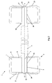
- Figure 2 presents a section view of the dumbbell of Figure 1;
- Figure 3 presents a cut away view of a weight assembly of Figures 1 or 2;
- Figure 4 presents a perspective view of a dumbbell having the end plate removed, according to an alternative embodiment of the invention;
- Figure 5 presents a perspective view of a dumbbell according to a further alternative embodiment of the invention;
- Figure 6a presents a perspective view of a dumbbell with the number disc removed, according to yet another embodiment of the invention; and
- Figure 6b presents a perspective view of the dumbbell of Figure 6a with the number disc inserted.
- Figure 7 presents an exploded view of the weight assembly and end plate of Figures 6a and 6b.
- Referring to Figure 1, the
exercise device 1 comprises abar 3 having end portions 4 at each end. Theexercise device 1 further comprise aweight assembly 5 which is mounted on an end portion 4 of thebar 3, with a second weight assembly mounted on the opposite end of the bar. The central portion of the bar comprises a handle portion 6. Theweight assembly 5 is axially retained on an end portion 4 of thebar 3 in one direction by a locatingmember 10. - The locating
member 10 may be a projection, such as a flange, or a collar. Preferably, awasher 11 is provided between the locatingmember 10 and theweight assembly 5. Thewasher 11 is preferably formed of hardened steel and acts to distribute the load from the locating member over a wider surface area of the lower surface of the weight assembly, as well as improving the surface contact between the locating member and the weight assembly, thereby reducing any wobble between thebar 3 and theweight assembly 5. - The
weight assembly 5 comprises aninner weight section 7, and anouter skin 8. Theinner weight section 7 is preferably formed from cast iron, although other suitable materials could also be used. Theouter skin 8 is preferably formed of rubber, polyurethane, or any other suitable resilient material, and is moulded over theinner weight section 7. Theouter skin 8 protects the inner weight section from damage and corrosion, as well as providing an aesthetically pleasing finish. Acentral bore 2 is formed in the weight assembly for receiving the end portion 4 of thebar 3. - Cast iron is commonly used to form dumbbell weights, as its density enables a weight of suitable size to be achieved, while also being relatively cheap to purchase and form into the required shape. However, cast iron used to produce weight assemblies at a commercially viable cost is often not of suitable quality to enable a smooth surface finish to be achieved. Therefore, when a bore is formed in a cast iron weight to accommodate the end portion of a bar, it is not possible to provide an interference fit between the end portion and the weight, as the required tolerances cannot be achieved. In addition, the surface imperfections are such that the end portion does not sit completely flush with the inner surface of the bore. Hence, there is movement between the end portion and weight, which results in loosening of the fixings securing the weight to the bar.
- To address this problem, there is provided in an embodiment of the present invention a
collar 16, for receiving the end portion 4 of thebar 3. Thecollar 16 is located between the end portion 4, and theinner weight section 7. Thecollar 16 is preferably cylindrical, and surrounds the periphery of the end portion 4. Preferably, thecollar 16 extends along the entire length of thecentral bore 2 of theweight assembly 5. The collar is preferably formed from seamless mild steel tubing, but may also be formed from any other suitable material. - In contrast to the cast iron of the
inner weight section 7, thecollar 16 may be easily machined to tight tolerances, and may be provided with a smooth surface finish. As such, an interference fit may be provided between the end portion 4 and thecollar 16, to prevent or limit movement therebetween. In particular, the interference fit prevents relative axial and rotational movement between the end portion 4 and thecollar 16. In this way, thecollar 16 provides a securing member, which has the advantage of obviating the requirement for threaded fastenings. - The
collar 16 is provided to prevent movement between the end portion 4 and theweight assembly 5. Therefore, as well as achieving a suitably toleranced fit between thecollar 16 and the end portion 4, it is also necessary to ensure that any movement between thecollar 16 and theweight assembly 5 is prevented. For the reasons discussed above in relation to the end portion 4, it is not possible to machine a bore in theinner weight section 7 suitable for providing a close fit with thecollar 16. Therefore, theinner weight section 7 is formed around thecollar 16 during the casting process. As such, theinner weight section 7 forms to the outer surface of thecollar 16. The collar obviates the need for subsequent machining of theinner weight section 7. Furthermore, the closest possible tolerance between thecollar 16 and theinner weight section 7 is achieved, which prevents lateral movement therebetween. - The
collar 16 comprises a longitudinal axis, as shown by line A-A in Figure 2. The longitudinal axis of thecollar 16 is coaxial with the longitudinal axis of thebar 3 when theweight assembly 5 is mounted on the end portion 4. To prevent relative axial movement between thecollar 16 and theweight assembly 5, a portion of theinner weight section 7 extends into thecollar 16, or vice versa. Preferably, the collar is provided with at least oneannular channel 18. Thechannel 18 is machined into the outer surface of thecollar 16, and preferably extends around its entire periphery. During the casting process, the molteninner weight section 7 penetrates into thechannel 18 and solidifies. Theinner weight section 7 is thus formed such that a portion of theinner weight section 7 extends into thecollar 16. The interaction between thechannel 18 and the portion of theinner weight section 7 extending into thecollar 16, prevents axial movement between theinner weight section 7 and thecollar 16. In the embodiment of the invention shown in Figure 3, thecollar 16 is provided with threechannels 18, although such is not essential and other numbers may be provided. Thecollar 16 may also be provided withchannels 18 extending along its length to prevent rotational movement between thecollar 16 and theweight assembly 5. - In an alternative embodiment, the
collar 16 may be provided with projections which radially extend away from its outer surface. The projections may comprise one or more radially extending ridges arranged around the periphery and/or axially, one or more dimples, a secondary collar, or any other member which radially extends away from the surface of the collar. Thecollar 16 may also be provided withchannels 18 extending around the outer surface in a spiral or helical formation, such that thechannels 18 restrict movement in both the radial and axial directions. Thecollar 16 may also be provided with both projections and recessed sections. In a further alternative embodiment, the outer surface of thecollar 16 may be tapered along the length of thecollar 16, such that the ends of thecollar 16 are both of greater diameter than some point along the length of the outer surface of the collar, or such that the ends of thecollar 16 are both of lesser diameter than some point along the length of thecollar 16. - A first securing member is provided to secure the
weight assembly 5 to the end portion 4. The first securing member may comprise anend plate 12. Theend plate 12 secures theweight assembly 5 to the end portion 4 independently of thecollar 16. It is necessary to provide a securing member in addition to the collar, as for all but the lightest of weights an interference fit is not sufficient to permanently secure a weight on a dumbbell bar. Preferably, theend plate 12, comprises a load bearing plate (not shown), and anouter skin 25. The outer skin is moulded around the load plate in a similar manner to theouter skin 8 of theweight assembly 5. - The
end plate 12 further comprises acentral aperture 26. Theend plate 12 covers arecess 21 in theouter skin 8 of theweight assembly 5, with the peripheral edge of theend plate 12 supported by theouter skin 8. Theend plate 12 is further supported about thecentral aperture 26 by afirst projection 17 extending from the end portion 4. Preferably, thefirst projection 17 is of reduced diameter relative to the end portion 4. Asecond projection 19, of reduced diameter relative to thefirst projection 17, extends from thefirst projection 17 and within thecentral aperture 26. - The
second projection 19 may comprise abore 15 extending through its centre, as shown in Figure 6a. Thebore 15 may extend downwards into thefirst projection 17, and into the main body of the end portion 4. Thebore 15 is provided to receive thespigot 13 of thenumber disc 9. Thedisc 9 may be used to display information relating to the weight of the dumbbell, logos, or other information or designs. Thespigot 13 extends from the rear surface of thedisc 9, and is received by thebore 15. Theend plate 12 may comprise arecess 26 for receiving thedisc 9, such that thedisc 9 is flush with surface of theend plate 12. Thedisc 9 obscures theweld 20, andsecond projection 19 from view. In the same way, theend plate 12 obscures the end portion 4 from view. - The
end plate 12 is secured to the end portion 4 of thebar 3. In one embodiment, theend plate 12 is secured to the end portion 4 by aweld 22. The weld is formed in thecentral aperture 26 of theend plate 12, and surrounds thesecond projection 19. Preferably thecentral aperture 26 is tapered, or counter-sunk to retain the weld more securely. Theweld 26 provides a permanent fixing, and obviates the need for a threaded fastener such a locking nut. Previously, it has not been possible to use a weld to permanently fix the weight assembly of a dumbbell, as movement between the end portion of the bar and the weight assembly would result in the weld cracking. However, the present invention provides acollar 16 which is cast into, and fixed relative to, theweight assembly 5, and which provides an interference fit with the end portion 4. As such, movement between the end portion 4 and theweight assembly 5 is prevented, thereby enabling the use of welds as a permanent fixing means. In a further advantage, by obviating the requirement for threaded fastenings, it is no longer required to provide theinner weight section 7 with a recess to accommodate the fastening below the upper surface of theweight assembly 5. - In an alternative embodiment, the
end plate 12 is secured by flaring thesecond projection member 19. The second projection is provided with a central bore. Theend plate 12 is placed onto the upper surface of theweight assembly 5 such that thesecond projection 19 extends within thecentral aperture 26. A tapered tool is then inserted into the central bore of thesecond projection 19 and a force applied such that the end of thesecond projection 19 is expanded in diameter. The expanded diameter of thesecond projection 19 is forced against the countersunkcentral aperture 26 of theend plate 12, and secures theend plate 12 is position. - Threaded fastenings are commonly used in the arrangements of the prior art as they allow a torque to be applied to the fastening to urge the weight assembly against the locating means of the bar, which is not possible with a passive securing means such as a weld. This problem is overcome in the present invention using the resilient force of the
outer skin 8. - During assembly of the dumbbell, the
end plate 12 is placed onto theouter skin 8 such that the central aperture is aligned with thesecond projection 19. A force is applied to the upper surface of theend plate 12, for example using a press such as a 40 tonne press, thereby compressing the portion of theouter skin 8 supporting theend plate 12. The height of thefirst projection 17 is selected such that it is a predetermined distance below the upper surface of theouter skin 8, which contacts and supports theend plate 12. Theouter skin 8 is compressed until theend plate 12 contacts thefirst projection 17. Theend plate 12 is then held in place and secured to the end portion 4 with a weld, by flaring the end of thesecond projection 19, or by any other suitable means. When the compressive force is subsequently removed, theouter skin 8 remains compressed. Due to its resilient properties, the compressedouter skin 8 applies a force to the weight assembly to urge it against the locatingmember 10. - In addition to the
end plate 12 and thecollar 16, a third securingmember 20 may be provided to secure theweight assembly 5 to the end portion 4, independently of theend plate 12 and thecollar 16. The third securingmember 20 is preferably a weld, such as a ring weld, which connects the end portion 4, thecollar 16, and the upper surface of theinner weight section 7 of theweight assembly 5. Each of the three securing members, comprising thecollar 16, theend plate 12, and the third securingmember 20, secures theweight assembly 5 to the end portion 4 independently of each other. The weight assembly may therefore be secured to the end portion by one of the three securing members alone, by two of the securing members in combination, or using all three. The third securingmember 20 is obscured from view by theend plate 12. - In an alternative embodiment, there is provided a
recess 21 in theweight assembly 5, as shown in Figure 3, adapted to receive theend plate 12. Preferably the recess is provided in theouter skin 8 of theweight assembly 5. Theend plate 12, as shown in Figures 6a, 6b, and 7, comprises a main body andprojections 25. Preferably there are provided twoprojections 31, formed from the outer skin. Therecess 21 is shaped such that it corresponds in shape to theend plate 12. Rotational movement of theend plate 12 is prevented by the engagement of theprojections 25 with therecess 21. Lateral or radial movement of theend plate 12 relative to theweight assembly 5 is prevented by the side walls of therecess 21. - It will be appreciated that in further embodiments various modifications to the specific arrangements described above and shown in the drawings may be made. For example, it is evident that the construction for securing the weights on the bar is not limited to applications in dumbbells or barbells but can also be applied to secure weights in other exercise equipment applications.
Claims (42)
- A method of manufacturing an exercise device, comprising:providing a bar, the bar comprising an end portion;providing a collar for receiving the end portion;providing a weight assembly;mounting the weight assembly on the end portion;providing a first securing member; andsecuring the weight assembly to the bar using the first securing member;characterised by the step of forming the weight section about the collar to form a weight assembly comprising a weight section and a collar.
- The method of claim 1, wherein the weight section is formed about the collar such that the collar is fixed relative to the weight section.
- The exercise device of claim 1 or 2, wherein the collar has a longitudinal axis, and wherein the collar is axially fixed relative to the weight section.
- The exercise device of any preceding claim, wherein a portion of the weight section extends inwardly of a portion of the collar to fix the collar relative to the weight section.
- The exercise device of any preceding claim, wherein a portion of the weight section extends into the collar to fix the collar relative to the weight section.
- The method of any preceding claim, wherein the collar comprises an outer surface, and the method further comprises forming at least one channel in the outer surface of the collar.
- The method of any preceding claim, wherein the first securing member comprises an end plate which engages with the weight assembly to at least axially secure the weight assembly to the end portion.
- The method of claim 7, wherein the end plate comprises a central aperture, and the end portion of the bar comprises a projection located within the central aperture of the end plate.
- The method of claim 8, wherein securing the end plate to the end portion comprises welding the end plate to the projection.
- The method of claim 7, wherein securing the end plate to the end portion comprises flaring the projection to retain the end plate against the weight assembly.
- The method of any preceding claim, further comprising providing a resilient member, and applying a force to the first securing member to compress the resilient member prior to the step of securing the first securing member to the end portion, such that the resilient member remains compressed when the first securing member is secured to the end portion and the force is removed from the first securing member.
- The method of claim 11, wherein the weight assembly further comprises an outer skin, and wherein resilient member comprises a resilient portion of the outer skin.
- The method of any preceding claim, further comprising providing a second securing member to further secure the weight assembly to the bar.
- The method of claim 13, wherein the second securing member comprises the collar.
- The method of any preceding claim, wherein an interference fit exists between the collar and the end portion.
- The method of any one of claims 13 to 15, further comprising the steps of providing a third securing member for securing the weight assembly to the bar, and securing the weight assembly to the bar using the third securing member.
- The method of claim 16, wherein the third securing member comprises a weld.
- The method of any preceding claim, wherein forming the weight section about the collar comprises casting the weight section about the collar.
- The method of any preceding claim, wherein the weight section is cast iron.
- The method of any preceding claim, wherein the exercise device is a dumbell.
- An exercise device comprising:a bar, the bar comprising an end portion;a weight assembly mounted on the end portion; anda first securing member for securing the weight assembly to the bar;wherein the weight assembly comprises a collar and a weight section formed about the collar, the collar being adapted to receive the end portion of the bar to mount the weight assembly on the bar.
- The exercise device of claim 21, wherein the weight section is formed about the collar such that the collar is fixed relative to the weight section.
- The exercise device of claim 21 or 22, wherein the collar has a longitudinal axis, and wherein the collar is axially fixed relative to the weight section.
- The exercise device of any one of claims 21 to 23, wherein a portion of the weight section extends inwardly of a portion of the collar to fix the collar relative to the weight section.
- The exercise device of any one of claims 21 to 24, wherein the collar comprises an outer surface about which the weight section is formed, the outer surface having at least one channel into which a portion of the weight section extends.
- The exercise device of claim 24, wherein at least one channel extends around at least part of the periphery of the collar.
- The exercise device of claim 25 or 26, wherein at least one channel extends along the length of the collar.
- The exercise device of any one of claims 21 to 27, wherein the first securing member comprises an end plate for engaging with the weight assembly to at least axially secure the weight assembly to the end portion.
- The exercise device of claim 28, wherein the end plate comprises a central aperture, and the end portion comprises a projection located within the central aperture of the end plate, and wherein the projection cooperates with the end plate to secure the weight assembly to the end portion.
- The exercise device of claim 29, wherein the projection is welded to the end plate.
- The exercise device of claim 29, wherein the projection is flared to retain the end plate against the weight assembly.
- The exercise device of any one of claims 21 to 31, further comprising a resilient member which is compressed when the first securing member is secured to the end portion of the bar to secure the weight assembly to the bar.
- The exercise device of claim 32, wherein the resilient member comprises an outer skin of the weight assembly.
- The exercise device of any one of claims 28 to 33, wherein the end plate is rotationally fixed relative to the weight assembly.
- The exercise device of any one of claims 21 to 34, further comprising a second securing member for securing the weight assembly to the bar, wherein the second securing member comprises the collar.
- The exercise device of claim 35, further comprising a third securing member for securing the weight assembly to the bar.
- The exercise device of claim 36, wherein the third securing member is a weld.
- The exercise device of any one of claims 21 to 37, wherein an interference fit is provided between the collar and the end portion.
- The exercise device of any one of claims 21 to 38, wherein the weight section is cast about the collar.
- The exercise device of any one of claims 21 to 39, wherein the exercise device is a dumbbell.
- A method of manufacturing an exercise device, comprising:providing a bar comprising an end portion and a locating member;providing a weight assembly;providing a resilient member;mounting the weight assembly on the end portion;providing an end plate for cooperating with the locating member to secure the weight assembly to the bar;applying a force to the end plate to cause the end plate to compress the resilient member;securing the end plate to the end portion while the resilient member is compressed; andremoving the force once the end plate is secured to the end portion;wherein the compressed resilient member applies a force to urge the weight assembly against the locating member.
- The method of claim 41, wherein the resilient member comprises a resilient portion of an outer skin of the weight assembly.
Applications Claiming Priority (1)
| Application Number | Priority Date | Filing Date | Title |
|---|---|---|---|
| GB0611625A GB2441977B (en) | 2006-06-13 | 2006-06-13 | An exercise device |
Publications (2)
| Publication Number | Publication Date |
|---|---|
| EP1867365A1 true EP1867365A1 (en) | 2007-12-19 |
| EP1867365B1 EP1867365B1 (en) | 2010-04-07 |
Family
ID=36745762
Family Applications (1)
| Application Number | Title | Priority Date | Filing Date |
|---|---|---|---|
| EP07252347A Active EP1867365B1 (en) | 2006-06-13 | 2007-06-11 | An exercise device |
Country Status (8)
| Country | Link |
|---|---|
| US (1) | US7922633B2 (en) |
| EP (1) | EP1867365B1 (en) |
| CN (1) | CN101088583B (en) |
| AT (1) | ATE463286T1 (en) |
| AU (1) | AU2007202354B8 (en) |
| DE (1) | DE602007005727D1 (en) |
| ES (1) | ES2341807T3 (en) |
| GB (1) | GB2441977B (en) |
Cited By (2)
| Publication number | Priority date | Publication date | Assignee | Title |
|---|---|---|---|---|
| WO2013045945A2 (en) | 2011-09-29 | 2013-04-04 | Escape Enviro Limited | Exercise weight structure |
| WO2017137045A1 (en) * | 2016-02-08 | 2017-08-17 | Andreas Wilhelm | Short dumbbell |
Families Citing this family (25)
| Publication number | Priority date | Publication date | Assignee | Title |
|---|---|---|---|---|
| USD574450S1 (en) * | 2006-12-15 | 2008-08-05 | Escape Fitness Limited | Dumbbell |
| US8281420B2 (en) * | 2008-02-22 | 2012-10-09 | Bemis Manufacturing Company | Hinge assembly for a toilet seat |
| USD692072S1 (en) * | 2012-02-02 | 2013-10-22 | Escape Fitness Limited | Rubber dumbbell |
| US8672816B2 (en) * | 2012-04-30 | 2014-03-18 | Usa Sports, Inc. | Dumbbells and barbells with improved attachments |
| CN104884133B (en) | 2013-03-14 | 2018-02-23 | 艾肯运动与健康公司 | Force exercise equipment with flywheel |
| EP3974036B1 (en) | 2013-12-26 | 2024-06-19 | iFIT Inc. | Magnetic resistance mechanism in a cable machine |
| US9486664B2 (en) | 2014-04-23 | 2016-11-08 | Jerry Prenatt | Exercise device |
| USD757190S1 (en) * | 2014-04-23 | 2016-05-24 | Jerry Prenatt | Exercise device |
| WO2015191445A1 (en) | 2014-06-09 | 2015-12-17 | Icon Health & Fitness, Inc. | Cable system incorporated into a treadmill |
| CN106470738A (en) * | 2014-06-25 | 2017-03-01 | 雀巢产品技术援助有限公司 | Training system for improving muscle strength |
| US10493313B2 (en) * | 2015-05-07 | 2019-12-03 | Xmt Solutions Llc | Mobile weight training system |
| US9713736B2 (en) * | 2015-08-19 | 2017-07-25 | Chien-Ping Kao | Dumbbell with detachable weights |
| US10940360B2 (en) | 2015-08-26 | 2021-03-09 | Icon Health & Fitness, Inc. | Strength exercise mechanisms |
| TWI644702B (en) | 2015-08-26 | 2018-12-21 | 美商愛康運動與健康公司 | Strength exercise mechanisms |
| US10441840B2 (en) | 2016-03-18 | 2019-10-15 | Icon Health & Fitness, Inc. | Collapsible strength exercise machine |
| US10293211B2 (en) | 2016-03-18 | 2019-05-21 | Icon Health & Fitness, Inc. | Coordinated weight selection |
| US10252109B2 (en) | 2016-05-13 | 2019-04-09 | Icon Health & Fitness, Inc. | Weight platform treadmill |
| US10661114B2 (en) | 2016-11-01 | 2020-05-26 | Icon Health & Fitness, Inc. | Body weight lift mechanism on treadmill |
| CN108310717B (en) * | 2018-01-25 | 2019-12-03 | 安徽梵玉康体教育咨询有限公司 | An intelligent weight-gaining device |
| SE542837C2 (en) * | 2018-11-09 | 2020-07-14 | Eleiko Group Ab | Dumbbell with rotating grip |
| US11376464B2 (en) * | 2019-06-05 | 2022-07-05 | Power Systems (Ps), Llc | Weight plate and logo ring |
| USD920449S1 (en) * | 2020-11-23 | 2021-05-25 | Danni WANG | Adjustable dumbbell |
| CN112717327B (en) * | 2021-01-26 | 2024-08-20 | 刘鹏 | Dumbbell |
| CN112587858B (en) * | 2021-01-26 | 2024-08-20 | 刘鹏 | Dumbbell (dumbbell) |
| US12491397B2 (en) * | 2022-02-02 | 2025-12-09 | Coulter Ventures, Llc. | Weightlifting barbell |
Citations (3)
| Publication number | Priority date | Publication date | Assignee | Title |
|---|---|---|---|---|
| DE2419221A1 (en) * | 1974-04-22 | 1975-10-30 | Josef Schnell | Dumbbell for sports activities - has tubular ends for mounting of weights, elasticated discs and retention collars |
| FR2529790A1 (en) * | 1982-07-09 | 1984-01-13 | Douchet Andre | New dumbbell, method of making the dumbbell weights, and mould for making the said weights. |
| GB2410197A (en) | 2004-01-23 | 2005-07-27 | Escape Fitness Ltd | Dumbbell having weight attached by two securing members |
Family Cites Families (43)
| Publication number | Priority date | Publication date | Assignee | Title |
|---|---|---|---|---|
| US1270034A (en) * | 1918-03-09 | 1918-06-18 | Donald G Krudop | Bar-bell. |
| US1946208A (en) * | 1930-06-12 | 1934-02-06 | Crawford Mcgregor & Canby Co | Method of coating articles with pyroxylin or the like |
| US2452458A (en) * | 1945-05-23 | 1948-10-26 | Worthington Pump & Mach Corp | Hub structure |
| US3151404A (en) * | 1961-05-16 | 1964-10-06 | Andrew F Schott | Abacus |
| US3171652A (en) * | 1962-03-21 | 1965-03-02 | Newman Dukes & Cline Inc | Exercising weight filled with solidified material |
| US3502326A (en) * | 1966-03-17 | 1970-03-24 | Bernarr C Schaeffer | Telescopically adjustable exercise bar |
| US3482834A (en) * | 1967-08-31 | 1969-12-09 | Diversified Prod | Cementitious dumbbell |
| FR2459056A1 (en) * | 1979-06-21 | 1981-01-09 | Guillier Lucien | Weight for dumb bells - has central sleeve fitting into hole in metal plate and covered with moulded rubber disc |
| CA1206177A (en) * | 1983-01-06 | 1986-06-17 | Edgar H. Lais | Exercise weight |
| US5180166A (en) * | 1990-10-16 | 1993-01-19 | Callaway Golf Company | Hollow, metallic golf club head with dendritic structure |
| US5407413A (en) * | 1993-01-07 | 1995-04-18 | Kupferman; Scott J. | Fitness excercise bar system |
| US5346449A (en) * | 1993-06-03 | 1994-09-13 | Schlagel Bruce E | Barbell system with improved locking feature |
| CN2158736Y (en) * | 1993-06-28 | 1994-03-16 | 张志明 | Fully-inclosed integral type casing tube for barbell rod |
| US5445587A (en) * | 1994-02-22 | 1995-08-29 | Brown; Lori | Liquid fillable dumbell |
| US5484367A (en) * | 1994-12-08 | 1996-01-16 | Martinez; Ralph E. | Weight set having means to prevent rotation of the weights on the bar |
| US5628716A (en) * | 1995-12-22 | 1997-05-13 | Brice; John P. | Adjustable weight exercise device |
| US6074327A (en) * | 1997-08-05 | 2000-06-13 | Black Diamond Equipment, Ltd. | Climbing hold with reinforcing sleeve |
| US6261211B1 (en) * | 1998-01-29 | 2001-07-17 | Suarez Corporation Industries | Dumbbell assembly |
| US5911651A (en) * | 1998-06-29 | 1999-06-15 | Liu; Chang-Fu | Dumbbell with weights having eccentric lock for securing to grip rod |
| US6312364B1 (en) * | 1998-08-19 | 2001-11-06 | Douglas Spriggs Selsam | Blow-moldable water-filled freeweights |
| US6602169B1 (en) * | 1999-05-17 | 2003-08-05 | Phil Patti | Apparatus and method of assembling and locking fixed dumbells, barbells and the like |
| US7001310B1 (en) * | 2001-10-15 | 2006-02-21 | Brice John P | Adjustable weight exercise device |
| US6776741B2 (en) * | 2002-01-03 | 2004-08-17 | Ht&R Sports Llc | Weight exercise apparatus |
| JP3730933B2 (en) * | 2002-04-17 | 2006-01-05 | 本田技研工業株式会社 | Wheel balance weight and manufacturing method thereof |
| US6971974B2 (en) * | 2002-06-14 | 2005-12-06 | Maryellen Bowman | Quick release ratcheting apparatus for a weight lift bar system |
| US7048678B2 (en) * | 2002-06-17 | 2006-05-23 | Technical Knockout, Inc. | Dumbbell having interlocking components |
| US7770354B2 (en) * | 2002-08-29 | 2010-08-10 | Bui Thuan H | Lightweight modular cementitious panel/tile for use in construction |
| US20040072662A1 (en) * | 2002-10-09 | 2004-04-15 | Landfair Craig D. | Stackable weight system |
| US7025713B2 (en) * | 2003-10-13 | 2006-04-11 | Icon Ip, Inc. | Weight lifting system with internal cam mechanism |
| US7300390B1 (en) * | 2004-09-14 | 2007-11-27 | Krull Mark A | Weight selection methods and apparatus |
| USD546908S1 (en) * | 2005-12-15 | 2007-07-17 | Usa Sports, Inc. | Dumbbell |
| USD545927S1 (en) * | 2005-12-15 | 2007-07-03 | Usa Sports, Inc. | Dumbbell |
| US7413533B2 (en) * | 2006-02-08 | 2008-08-19 | Asai Regent Limited | Adjustable dumbbell |
| GB2435222C (en) * | 2006-02-18 | 2017-12-06 | Escape Fitness Ltd | An exercise device |
| USD562920S1 (en) * | 2006-03-17 | 2008-02-26 | Escape Fitness Limited | Dumbbell |
| USD567311S1 (en) * | 2006-03-17 | 2008-04-22 | Escape Fitness Limited | Dumbbell |
| US20070249475A1 (en) * | 2006-04-24 | 2007-10-25 | Guofang Cao | Fixed Weight Dumbbell Assembly |
| GB2439221B (en) * | 2006-06-13 | 2008-05-28 | Escape Fitness Ltd | An exercise device |
| US7780582B2 (en) * | 2006-06-22 | 2010-08-24 | Ace Specialty, Inc. | Method and apparatus for magnetically coupling incremental weights to exercise apparatus |
| US7789813B2 (en) * | 2006-06-22 | 2010-09-07 | Ace Specialty, Inc. | Dumbbell and adaptor with securable incremental weight plate feature |
| US20080026920A1 (en) * | 2006-07-27 | 2008-01-31 | Annaniy Berenshteyn | Weightlifting apparatus for pronation and supination exercises |
| US7452312B2 (en) * | 2006-07-27 | 2008-11-18 | Ping Liu | Adjustable dumbbell system |
| US20080200315A1 (en) * | 2007-02-15 | 2008-08-21 | Vincent Lin | Rubber barbell weight with at least one colored rubber belt and a method of making the same |
-
2006
- 2006-06-13 GB GB0611625A patent/GB2441977B/en active Active
-
2007
- 2007-02-26 US US11/678,662 patent/US7922633B2/en active Active
- 2007-05-24 AU AU2007202354A patent/AU2007202354B8/en active Active
- 2007-06-11 AT AT07252347T patent/ATE463286T1/en not_active IP Right Cessation
- 2007-06-11 ES ES07252347T patent/ES2341807T3/en active Active
- 2007-06-11 DE DE602007005727T patent/DE602007005727D1/en active Active
- 2007-06-11 EP EP07252347A patent/EP1867365B1/en active Active
- 2007-06-13 CN CN2007101123935A patent/CN101088583B/en not_active Expired - Fee Related
Patent Citations (3)
| Publication number | Priority date | Publication date | Assignee | Title |
|---|---|---|---|---|
| DE2419221A1 (en) * | 1974-04-22 | 1975-10-30 | Josef Schnell | Dumbbell for sports activities - has tubular ends for mounting of weights, elasticated discs and retention collars |
| FR2529790A1 (en) * | 1982-07-09 | 1984-01-13 | Douchet Andre | New dumbbell, method of making the dumbbell weights, and mould for making the said weights. |
| GB2410197A (en) | 2004-01-23 | 2005-07-27 | Escape Fitness Ltd | Dumbbell having weight attached by two securing members |
Cited By (4)
| Publication number | Priority date | Publication date | Assignee | Title |
|---|---|---|---|---|
| WO2013045945A2 (en) | 2011-09-29 | 2013-04-04 | Escape Enviro Limited | Exercise weight structure |
| US10543650B2 (en) | 2011-09-29 | 2020-01-28 | Escape Enviro Limited | Exercise weight structure |
| WO2017137045A1 (en) * | 2016-02-08 | 2017-08-17 | Andreas Wilhelm | Short dumbbell |
| US10729928B2 (en) | 2016-02-08 | 2020-08-04 | Andreas Wilhelm | Short dumbbell |
Also Published As
| Publication number | Publication date |
|---|---|
| AU2007202354A1 (en) | 2008-01-03 |
| GB0611625D0 (en) | 2006-07-19 |
| US20070287611A1 (en) | 2007-12-13 |
| AU2007202354B2 (en) | 2013-05-16 |
| DE602007005727D1 (en) | 2010-05-20 |
| GB2441977B (en) | 2008-05-28 |
| ES2341807T3 (en) | 2010-06-28 |
| CN101088583B (en) | 2012-11-28 |
| ATE463286T1 (en) | 2010-04-15 |
| CN101088583A (en) | 2007-12-19 |
| EP1867365B1 (en) | 2010-04-07 |
| GB2441977A (en) | 2008-03-26 |
| US7922633B2 (en) | 2011-04-12 |
| AU2007202354B8 (en) | 2013-09-05 |
Similar Documents
| Publication | Publication Date | Title |
|---|---|---|
| US7922633B2 (en) | Exercise device | |
| US7527582B2 (en) | Exercise device | |
| DE102012022148B4 (en) | Two-part wheel star with profile spokes | |
| EP2639135B1 (en) | Support device for steering column | |
| US8882146B2 (en) | Column unit for an electric power steering apparatus | |
| EP3302728B1 (en) | Grip apparatus for exercise equipment and method for making thereof | |
| KR20130011986A (en) | A functional element having features providing security against rotation and also a component assembly consisting of the functional element and a sheet metal part | |
| US8672816B2 (en) | Dumbbells and barbells with improved attachments | |
| US20110010921A1 (en) | Functional element for the attachment to a sheet metal part, component assembly manufactured from these and also a method for the attachment of the functional element to a sheet metal part | |
| JPH0783222A (en) | Female type clinch clamper with cold-molded lock flange and mounting method thereof | |
| CN104903037A (en) | Pre-loading damping system | |
| DE102006028771A1 (en) | Hydrodynamic torque converter and method of making such | |
| JP2009502539A (en) | Tool assembly | |
| GB2439221A (en) | Weight mounting for exercise device | |
| US12072005B2 (en) | Threaded nut of a ball screw drive, and method for producing same | |
| EP0565919A1 (en) | Socket for a power driven screwdriver | |
| EP2614862B1 (en) | Golf club | |
| US11180182B2 (en) | Steering apparatus of vehicle | |
| US20180215408A1 (en) | Steering Column Assembly | |
| EP1660769A1 (en) | Split piston for an internal combustion engine | |
| JPS61181772A (en) | Steering wheel core bar | |
| DE102007038971A1 (en) | Machine element for a shaft-hub connection and method of manufacturing a shaft-hub connection | |
| CN217645748U (en) | Constant-torque body-building chest expander with integrated installation fixing seat and strength training machine | |
| CN224013794U (en) | Motorcycle handle pressing plate | |
| GB2329008A (en) | Coupling of a steering wheel to a steering shaft |
Legal Events
| Date | Code | Title | Description |
|---|---|---|---|
| PUAI | Public reference made under article 153(3) epc to a published international application that has entered the european phase |
Free format text: ORIGINAL CODE: 0009012 |
|
| AK | Designated contracting states |
Kind code of ref document: A1 Designated state(s): AT BE BG CH CY CZ DE DK EE ES FI FR GB GR HU IE IS IT LI LT LU LV MC MT NL PL PT RO SE SI SK TR |
|
| AX | Request for extension of the european patent |
Extension state: AL BA HR MK YU |
|
| 17P | Request for examination filed |
Effective date: 20080522 |
|
| 17Q | First examination report despatched |
Effective date: 20080619 |
|
| AKX | Designation fees paid |
Designated state(s): AT BE BG CH CY CZ DE DK EE ES FI FR GB GR HU IE IS IT LI LT LU LV MC MT NL PL PT RO SE SI SK TR |
|
| GRAP | Despatch of communication of intention to grant a patent |
Free format text: ORIGINAL CODE: EPIDOSNIGR1 |
|
| GRAJ | Information related to disapproval of communication of intention to grant by the applicant or resumption of examination proceedings by the epo deleted |
Free format text: ORIGINAL CODE: EPIDOSDIGR1 |
|
| GRAP | Despatch of communication of intention to grant a patent |
Free format text: ORIGINAL CODE: EPIDOSNIGR1 |
|
| GRAJ | Information related to disapproval of communication of intention to grant by the applicant or resumption of examination proceedings by the epo deleted |
Free format text: ORIGINAL CODE: EPIDOSDIGR1 |
|
| GRAP | Despatch of communication of intention to grant a patent |
Free format text: ORIGINAL CODE: EPIDOSNIGR1 |
|
| GRAS | Grant fee paid |
Free format text: ORIGINAL CODE: EPIDOSNIGR3 |
|
| GRAA | (expected) grant |
Free format text: ORIGINAL CODE: 0009210 |
|
| RBV | Designated contracting states (corrected) |
Designated state(s): AT BE BG CH CY CZ DE DK EE ES FI FR GR HU IE IS IT LI LT LU LV MC MT NL PL PT RO SE SI SK TR |
|
| AK | Designated contracting states |
Kind code of ref document: B1 Designated state(s): AT BE BG CH CY CZ DE DK EE ES FI FR GR HU IE IS IT LI LT LU LV MC MT NL PL PT RO SE SI SK TR |
|
| REG | Reference to a national code |
Ref country code: CH Ref legal event code: EP |
|
| REG | Reference to a national code |
Ref country code: IE Ref legal event code: FG4D |
|
| REF | Corresponds to: |
Ref document number: 602007005727 Country of ref document: DE Date of ref document: 20100520 Kind code of ref document: P |
|
| REG | Reference to a national code |
Ref country code: ES Ref legal event code: FG2A Ref document number: 2341807 Country of ref document: ES Kind code of ref document: T3 |
|
| REG | Reference to a national code |
Ref country code: NL Ref legal event code: T3 |
|
| PG25 | Lapsed in a contracting state [announced via postgrant information from national office to epo] |
Ref country code: SI Free format text: LAPSE BECAUSE OF FAILURE TO SUBMIT A TRANSLATION OF THE DESCRIPTION OR TO PAY THE FEE WITHIN THE PRESCRIBED TIME-LIMIT Effective date: 20100407 |
|
| LTIE | Lt: invalidation of european patent or patent extension |
Effective date: 20100407 |
|
| PG25 | Lapsed in a contracting state [announced via postgrant information from national office to epo] |
Ref country code: LT Free format text: LAPSE BECAUSE OF FAILURE TO SUBMIT A TRANSLATION OF THE DESCRIPTION OR TO PAY THE FEE WITHIN THE PRESCRIBED TIME-LIMIT Effective date: 20100407 Ref country code: SE Free format text: LAPSE BECAUSE OF FAILURE TO SUBMIT A TRANSLATION OF THE DESCRIPTION OR TO PAY THE FEE WITHIN THE PRESCRIBED TIME-LIMIT Effective date: 20100407 |
|
| PG25 | Lapsed in a contracting state [announced via postgrant information from national office to epo] |
Ref country code: AT Free format text: LAPSE BECAUSE OF FAILURE TO SUBMIT A TRANSLATION OF THE DESCRIPTION OR TO PAY THE FEE WITHIN THE PRESCRIBED TIME-LIMIT Effective date: 20100407 Ref country code: LV Free format text: LAPSE BECAUSE OF FAILURE TO SUBMIT A TRANSLATION OF THE DESCRIPTION OR TO PAY THE FEE WITHIN THE PRESCRIBED TIME-LIMIT Effective date: 20100407 Ref country code: FI Free format text: LAPSE BECAUSE OF FAILURE TO SUBMIT A TRANSLATION OF THE DESCRIPTION OR TO PAY THE FEE WITHIN THE PRESCRIBED TIME-LIMIT Effective date: 20100407 Ref country code: IS Free format text: LAPSE BECAUSE OF FAILURE TO SUBMIT A TRANSLATION OF THE DESCRIPTION OR TO PAY THE FEE WITHIN THE PRESCRIBED TIME-LIMIT Effective date: 20100807 |
|
| PG25 | Lapsed in a contracting state [announced via postgrant information from national office to epo] |
Ref country code: PL Free format text: LAPSE BECAUSE OF FAILURE TO SUBMIT A TRANSLATION OF THE DESCRIPTION OR TO PAY THE FEE WITHIN THE PRESCRIBED TIME-LIMIT Effective date: 20100407 Ref country code: CY Free format text: LAPSE BECAUSE OF FAILURE TO SUBMIT A TRANSLATION OF THE DESCRIPTION OR TO PAY THE FEE WITHIN THE PRESCRIBED TIME-LIMIT Effective date: 20100519 |
|
| PG25 | Lapsed in a contracting state [announced via postgrant information from national office to epo] |
Ref country code: MC Free format text: LAPSE BECAUSE OF NON-PAYMENT OF DUE FEES Effective date: 20100630 Ref country code: EE Free format text: LAPSE BECAUSE OF FAILURE TO SUBMIT A TRANSLATION OF THE DESCRIPTION OR TO PAY THE FEE WITHIN THE PRESCRIBED TIME-LIMIT Effective date: 20100407 Ref country code: DK Free format text: LAPSE BECAUSE OF FAILURE TO SUBMIT A TRANSLATION OF THE DESCRIPTION OR TO PAY THE FEE WITHIN THE PRESCRIBED TIME-LIMIT Effective date: 20100407 Ref country code: PT Free format text: LAPSE BECAUSE OF FAILURE TO SUBMIT A TRANSLATION OF THE DESCRIPTION OR TO PAY THE FEE WITHIN THE PRESCRIBED TIME-LIMIT Effective date: 20100809 |
|
| PLBE | No opposition filed within time limit |
Free format text: ORIGINAL CODE: 0009261 |
|
| STAA | Information on the status of an ep patent application or granted ep patent |
Free format text: STATUS: NO OPPOSITION FILED WITHIN TIME LIMIT |
|
| PG25 | Lapsed in a contracting state [announced via postgrant information from national office to epo] |
Ref country code: SK Free format text: LAPSE BECAUSE OF FAILURE TO SUBMIT A TRANSLATION OF THE DESCRIPTION OR TO PAY THE FEE WITHIN THE PRESCRIBED TIME-LIMIT Effective date: 20100407 Ref country code: RO Free format text: LAPSE BECAUSE OF FAILURE TO SUBMIT A TRANSLATION OF THE DESCRIPTION OR TO PAY THE FEE WITHIN THE PRESCRIBED TIME-LIMIT Effective date: 20100407 Ref country code: BE Free format text: LAPSE BECAUSE OF FAILURE TO SUBMIT A TRANSLATION OF THE DESCRIPTION OR TO PAY THE FEE WITHIN THE PRESCRIBED TIME-LIMIT Effective date: 20100407 Ref country code: CZ Free format text: LAPSE BECAUSE OF FAILURE TO SUBMIT A TRANSLATION OF THE DESCRIPTION OR TO PAY THE FEE WITHIN THE PRESCRIBED TIME-LIMIT Effective date: 20100407 |
|
| 26N | No opposition filed |
Effective date: 20110110 |
|
| PG25 | Lapsed in a contracting state [announced via postgrant information from national office to epo] |
Ref country code: MT Free format text: LAPSE BECAUSE OF FAILURE TO SUBMIT A TRANSLATION OF THE DESCRIPTION OR TO PAY THE FEE WITHIN THE PRESCRIBED TIME-LIMIT Effective date: 20100407 Ref country code: GR Free format text: LAPSE BECAUSE OF FAILURE TO SUBMIT A TRANSLATION OF THE DESCRIPTION OR TO PAY THE FEE WITHIN THE PRESCRIBED TIME-LIMIT Effective date: 20100708 Ref country code: IE Free format text: LAPSE BECAUSE OF NON-PAYMENT OF DUE FEES Effective date: 20100611 |
|
| REG | Reference to a national code |
Ref country code: CH Ref legal event code: PL |
|
| PG25 | Lapsed in a contracting state [announced via postgrant information from national office to epo] |
Ref country code: LI Free format text: LAPSE BECAUSE OF NON-PAYMENT OF DUE FEES Effective date: 20110630 Ref country code: CH Free format text: LAPSE BECAUSE OF NON-PAYMENT OF DUE FEES Effective date: 20110630 |
|
| PG25 | Lapsed in a contracting state [announced via postgrant information from national office to epo] |
Ref country code: HU Free format text: LAPSE BECAUSE OF FAILURE TO SUBMIT A TRANSLATION OF THE DESCRIPTION OR TO PAY THE FEE WITHIN THE PRESCRIBED TIME-LIMIT Effective date: 20101008 Ref country code: LU Free format text: LAPSE BECAUSE OF NON-PAYMENT OF DUE FEES Effective date: 20100611 Ref country code: BG Free format text: LAPSE BECAUSE OF FAILURE TO SUBMIT A TRANSLATION OF THE DESCRIPTION OR TO PAY THE FEE WITHIN THE PRESCRIBED TIME-LIMIT Effective date: 20100407 |
|
| PG25 | Lapsed in a contracting state [announced via postgrant information from national office to epo] |
Ref country code: TR Free format text: LAPSE BECAUSE OF FAILURE TO SUBMIT A TRANSLATION OF THE DESCRIPTION OR TO PAY THE FEE WITHIN THE PRESCRIBED TIME-LIMIT Effective date: 20100407 |
|
| PG25 | Lapsed in a contracting state [announced via postgrant information from national office to epo] |
Ref country code: BG Free format text: LAPSE BECAUSE OF FAILURE TO SUBMIT A TRANSLATION OF THE DESCRIPTION OR TO PAY THE FEE WITHIN THE PRESCRIBED TIME-LIMIT Effective date: 20100707 |
|
| REG | Reference to a national code |
Ref country code: FR Ref legal event code: PLFP Year of fee payment: 10 |
|
| REG | Reference to a national code |
Ref country code: FR Ref legal event code: PLFP Year of fee payment: 11 |
|
| REG | Reference to a national code |
Ref country code: FR Ref legal event code: PLFP Year of fee payment: 12 |
|
| PGFP | Annual fee paid to national office [announced via postgrant information from national office to epo] |
Ref country code: DE Payment date: 20250618 Year of fee payment: 19 |
|
| PGFP | Annual fee paid to national office [announced via postgrant information from national office to epo] |
Ref country code: NL Payment date: 20250618 Year of fee payment: 19 |
|
| PGFP | Annual fee paid to national office [announced via postgrant information from national office to epo] |
Ref country code: FR Payment date: 20250620 Year of fee payment: 19 |
|
| PGFP | Annual fee paid to national office [announced via postgrant information from national office to epo] |
Ref country code: ES Payment date: 20250728 Year of fee payment: 19 |
|
| PGFP | Annual fee paid to national office [announced via postgrant information from national office to epo] |
Ref country code: IT Payment date: 20250624 Year of fee payment: 19 |