EP1867296A1 - High frequency treatment instrument - Google Patents
High frequency treatment instrument Download PDFInfo
- Publication number
- EP1867296A1 EP1867296A1 EP07011488A EP07011488A EP1867296A1 EP 1867296 A1 EP1867296 A1 EP 1867296A1 EP 07011488 A EP07011488 A EP 07011488A EP 07011488 A EP07011488 A EP 07011488A EP 1867296 A1 EP1867296 A1 EP 1867296A1
- Authority
- EP
- European Patent Office
- Prior art keywords
- high frequency
- impedance
- electrical circuit
- treatment instrument
- forceps
- Prior art date
- Legal status (The legal status is an assumption and is not a legal conclusion. Google has not performed a legal analysis and makes no representation as to the accuracy of the status listed.)
- Granted
Links
Images



Classifications
-
- A—HUMAN NECESSITIES
- A61—MEDICAL OR VETERINARY SCIENCE; HYGIENE
- A61B—DIAGNOSIS; SURGERY; IDENTIFICATION
- A61B18/00—Surgical instruments, devices or methods for transferring non-mechanical forms of energy to or from the body
- A61B18/04—Surgical instruments, devices or methods for transferring non-mechanical forms of energy to or from the body by heating
- A61B18/12—Surgical instruments, devices or methods for transferring non-mechanical forms of energy to or from the body by heating by passing a current through the tissue to be heated, e.g. high-frequency current
- A61B18/14—Probes or electrodes therefor
-
- A—HUMAN NECESSITIES
- A61—MEDICAL OR VETERINARY SCIENCE; HYGIENE
- A61B—DIAGNOSIS; SURGERY; IDENTIFICATION
- A61B18/00—Surgical instruments, devices or methods for transferring non-mechanical forms of energy to or from the body
- A61B18/04—Surgical instruments, devices or methods for transferring non-mechanical forms of energy to or from the body by heating
- A61B18/12—Surgical instruments, devices or methods for transferring non-mechanical forms of energy to or from the body by heating by passing a current through the tissue to be heated, e.g. high-frequency current
- A61B18/14—Probes or electrodes therefor
- A61B18/1442—Probes having pivoting end effectors, e.g. forceps
- A61B18/1445—Probes having pivoting end effectors, e.g. forceps at the distal end of a shaft, e.g. forceps or scissors at the end of a rigid rod
-
- A—HUMAN NECESSITIES
- A61—MEDICAL OR VETERINARY SCIENCE; HYGIENE
- A61B—DIAGNOSIS; SURGERY; IDENTIFICATION
- A61B18/00—Surgical instruments, devices or methods for transferring non-mechanical forms of energy to or from the body
- A61B18/04—Surgical instruments, devices or methods for transferring non-mechanical forms of energy to or from the body by heating
- A61B18/12—Surgical instruments, devices or methods for transferring non-mechanical forms of energy to or from the body by heating by passing a current through the tissue to be heated, e.g. high-frequency current
- A61B18/14—Probes or electrodes therefor
- A61B18/1492—Probes or electrodes therefor having a flexible, catheter-like structure, e.g. for heart ablation
-
- A—HUMAN NECESSITIES
- A61—MEDICAL OR VETERINARY SCIENCE; HYGIENE
- A61B—DIAGNOSIS; SURGERY; IDENTIFICATION
- A61B18/00—Surgical instruments, devices or methods for transferring non-mechanical forms of energy to or from the body
- A61B2018/00571—Surgical instruments, devices or methods for transferring non-mechanical forms of energy to or from the body for achieving a particular surgical effect
- A61B2018/00595—Cauterization
-
- A—HUMAN NECESSITIES
- A61—MEDICAL OR VETERINARY SCIENCE; HYGIENE
- A61B—DIAGNOSIS; SURGERY; IDENTIFICATION
- A61B18/00—Surgical instruments, devices or methods for transferring non-mechanical forms of energy to or from the body
- A61B2018/00636—Sensing and controlling the application of energy
- A61B2018/00773—Sensed parameters
- A61B2018/00875—Resistance or impedance
-
- A—HUMAN NECESSITIES
- A61—MEDICAL OR VETERINARY SCIENCE; HYGIENE
- A61B—DIAGNOSIS; SURGERY; IDENTIFICATION
- A61B18/00—Surgical instruments, devices or methods for transferring non-mechanical forms of energy to or from the body
- A61B18/04—Surgical instruments, devices or methods for transferring non-mechanical forms of energy to or from the body by heating
- A61B18/12—Surgical instruments, devices or methods for transferring non-mechanical forms of energy to or from the body by heating by passing a current through the tissue to be heated, e.g. high-frequency current
- A61B18/14—Probes or electrodes therefor
- A61B2018/1405—Electrodes having a specific shape
- A61B2018/1407—Loop
-
- A—HUMAN NECESSITIES
- A61—MEDICAL OR VETERINARY SCIENCE; HYGIENE
- A61B—DIAGNOSIS; SURGERY; IDENTIFICATION
- A61B18/00—Surgical instruments, devices or methods for transferring non-mechanical forms of energy to or from the body
- A61B18/04—Surgical instruments, devices or methods for transferring non-mechanical forms of energy to or from the body by heating
- A61B18/12—Surgical instruments, devices or methods for transferring non-mechanical forms of energy to or from the body by heating by passing a current through the tissue to be heated, e.g. high-frequency current
- A61B18/14—Probes or electrodes therefor
- A61B2018/1405—Electrodes having a specific shape
- A61B2018/1407—Loop
- A61B2018/141—Snare
-
- A—HUMAN NECESSITIES
- A61—MEDICAL OR VETERINARY SCIENCE; HYGIENE
- A61B—DIAGNOSIS; SURGERY; IDENTIFICATION
- A61B18/00—Surgical instruments, devices or methods for transferring non-mechanical forms of energy to or from the body
- A61B18/04—Surgical instruments, devices or methods for transferring non-mechanical forms of energy to or from the body by heating
- A61B18/12—Surgical instruments, devices or methods for transferring non-mechanical forms of energy to or from the body by heating by passing a current through the tissue to be heated, e.g. high-frequency current
- A61B18/14—Probes or electrodes therefor
- A61B2018/1405—Electrodes having a specific shape
- A61B2018/144—Wire
Definitions
- the present invention relates to a high frequency treatment instrument.
- Priority is claimed on Japanese Patent Application No. 2006-164630, filed on June 14, 2006 , the content of which is incorporated herein by reference.
- high frequency treatment instruments that perform various treatments while checking observation images taken by an endoscope are being used.
- One conventionally known high frequency treatment instrument dissects, solidifies, and stops bleeding of living tissue by supplying a high frequency current to treatment electrodes provided on a distal end thereof (for example see Japanese Unexamined Patent Application, First Publication No. 2005-58344 ).
- the present invention has been realized in view of the above problems, and aims to provide a high frequency treatment instrument which can efficiently supply a high frequency current to treatment electrodes, and can reduce power consumption.
- the present invention uses the following means.
- a first aspect of the high frequency treatment instrument includes an electrical circuit which is connected to a high frequency power source which generates a high frequency voltage in which at least one treatment electrode is included for performing conduction treatment using a high frequency current to a target tissue by applying a high frequency voltage from the high frequency power source, in which the high frequency treatment instrument includes an impedance adjust part which is connected to the electrical circuit and based on the frequency of the high frequency power source changes at least one of an actual number part and an imaginary number part of an impedance of the electrical circuit.
- This high frequency treatment instrument of first aspect can change the impedance of the electrical circuit so as to increase/decrease the high frequency current which flows in the electrical circuit when the high frequency power is supplied.
- the high frequency treatment instrument in which the impedance adjust part changes the impedance of the electrical circuit when the high frequency power source and the treatment electrode are made conductive.
- This high frequency treatment instrument of second aspect can adjust the flow of high frequency current to a current of a more appropriate magnitude by changing the impedance of the electrical circuit including the high frequency power.
- the impedance adjust part changes the impedance of the electrical circuit when the treatment electrode contacts the target tissue.
- This high frequency treatment instrument of third aspect changes the impedance of the electrical circuit when the treatment electrode actually contacts the target tissue, whereby a high frequency current of a more appropriate magnitude can be supplied at the time of the treatment.
- the impedance adjust part includes a coil part having an inductance or a capacitor having a capacitance, and is connected in series with the electrical circuit.
- the impedance adjust part when the inductance of the electrical circuit is large, can include the capacitor part, and when the capacitance of the electrical a circuit is large, the impedance adjust part can include the coil part.
- the square of the imaginary number part of the impedance of the electrical circuit can be changed to be minimized, and the magnitude of the impedance can be reduced.
- the impedance adjust part includes an electrical resistor, and is connected in series with the electrical circuit.
- This high frequency treatment instrument of fifth aspect can change the overall impedance by changing the actual number part of the impedance of the electrical circuit. Even if the load characteristics of the high frequency power source fluctuate due to fluctuation in the impedance of the electrical circuit that incorporates the impedance of the target tissue, the magnitude of the electrical resistor can be adjusted to obtain an output approximately at a rating power.
- the high frequency treatment instrument in which the treatment electrode includes an elongated coil sheath connected to a distal end thereof, and the coil sheath constitutes the coil part.
- This high frequency treatment instrument of sixth aspect uses the coil sheath as an impedance adjust part which can adjust the inductance by changing the wire diameter, material, and winding number of the coil sheath.
- the high frequency treatment instrument in which the treatment electrode includes a first electrode and a second electrode that create mutually different potential differences.
- This high frequency treatment instrument of seventh aspect can change the impedance of the electrical circuit incorporating the impedance between supply lines to the first electrode and the second electrode.
- an electrical circuit which is connected to a high frequency power source which generates a high frequency voltage in which at least one treatment electrode is included for performing conduction treatment using a high frequency current to a target tissue by applying a high frequency voltage from the high frequency power source, in which the high frequency treatment instrument includes an impedance adjust part which is connected to the electrical circuit and which is set such that the magnitude of the impedance of the electrical circuit is minimized with respect to the frequency of the high frequency power source.
- the high frequency treatment instrument of eighth aspect minimizes the magnitude of the impedance with respect to the high frequency current which flows in the electrical circuit when the high frequency power is supplied, appropriate conduction efficiency can be obtained.
- a high frequency current can be efficiently supplied to a treatment electrode, whereby power consumption can be reduced.
- FIG.S. 1 and 2 A first embodiment of the invention will be explained with reference to FIG.S. 1 and 2.
- a high frequency forceps (high frequency treatment instrument) 1 includes an electrical circuit 7 which is connected via a connection cord 3 to a high frequency power source 2 which generates a high frequency voltage in which a pair of forceps pieces (treatment electrodes) 6A and 6B which performs conduction treatment to a target tissue S by using high frequency current between a return electrode 5 with the high frequency voltage applied from the high frequency power source 2, and is known as a monopolar high frequency forceps.
- the high frequency forceps includes an elongated flexible tube 8 in which the pair of forceps pieces 6A and 6B are arranged at distal end thereof, an operation part 10 for opening and closing the pair of forceps pieces 6A and 6B, and an impedance adjust part 11 that is connected to the electrical circuit 7 and, based on the frequency of the high frequency power source 2, changes at least one of an actual number part and an imaginary number part of the impedance of the electrical circuit 7.
- the flexible tube 8 includes a stainless steel coil sheath 12 and a resin outer sheath 13 that covers an outer side of the coil sheath 12 in which operation wires 15A and 15B are arranged so as to advance and retreat with respect to the flexible tube 8.
- a support part 16 is connected to the distal end of the coil sheath 12 to which the pair of forceps pieces 6A and 6B are supported so as to pivot freely. Proximal ends of the pair of forceps pieces 6A and 6B and distal ends of the operation wires 15A and 15B are rotatably connected to the support part 16.
- the operation part 10 includes an operation part body 17 to which the proximal end of the flexible tube 8 is connected, and a slider 18 which is disposed so as to advance and retreat with respect to the operation part body 17.
- a slider 18 which is disposed so as to advance and retreat with respect to the operation part body 17.
- an electrode terminal 20 to which a connection cord 3 is connected is disposed, and proximal ends of the operation wires 15A and 15B are connected to the slider 18 via a wire attachment part 21.
- the impedance adjust part 11 includes a capacitor part 22 whose capacitance is set to a predetermined value so as to minimize the impedance of the electrical circuit 7.
- the capacitance of the capacitor part 22 is based on the value of the impedance when a predetermined high frequency current is supplied to the electrical circuit 7, which is formed when the electrode terminal 20 and the high frequency power source 2 are connected via the connection cord 3 with respect to a high frequency forceps without the impedance adjust part 11 and when the target tissue S is clasped by the pair of forceps pieces 6A and 6B with the return plate 5 disposed thereto.
- the impedance adjust part 11 is connected in series to the electrical circuit 7. In the embodiment as shown in F. 2, it is connected in series to the electrode terminal 20.
- the capacitor part may have a capacitance that is determined based on the impedance of an electrical circuit formed by connecting the electrode terminal 20 and the high frequency power source 2 via the connection cord 3 without clasping the target tissue S.
- it may have a capacitance that is determined based on an electrical circuit of a high frequency forceps single unit formed from the pair of forceps pieces 6A and 6B, the operation wires 15A and 15B, and the electrode terminal 20.
- the electrode terminal 20 and the high frequency power source 2 are connected via the connection cord 3, and a material having similar impedance as the target tissue S is mounted on the return plate 5.
- the slider 18 is then retreated from the operation part body 17 and clasped by the pair of forceps pieces 6A and 6B. In this state, a high frequency current having a predetermined frequency is supplied, and the impedance of the overall electrical circuit 7 is measured.
- Equation (1) expresses the magnitude (
- R 0 , L 0 , and C 0 respectively represent the resistance ( ⁇ ), the inductance (H), and the capacitance (F) of an existing electrical circuit, while f represents the frequency of the high frequency current.
- Z 0 R 0 2 + ( 2 ⁇ ⁇ fL 0 - 1 2 ⁇ ⁇ fC 0 ⁇ ) 2
- a capacitance (C 1 ) which minimizes a portion relating to the square of the imaginary number part of the equation (1) is calculated.
- An impedance adjust part 11 which includes a capacitor part 22 whose capacitance satisfies this capacitance (C 1 ) is connected in series to the electrode terminal 20.
- the impedance adjust part 11 can be connected after measuring the impedance at that point, or an impedance adjust part 11 that is designed based on an impedance ascertained beforehand can be assembled in a manufacturing process of the high frequency forceps 1.
- An endoscope having an unillustrated treatment instrument channel is inserted into a test body where the return plate 5 is placed, and a distal end part of the endoscope is disposed near the target tissue S.
- the flexible tube 8 of the high frequency forceps 1 including the impedance adjust part 11 is then inserted into the channel, and is protruded from the channel towards the target tissue S.
- the high frequency forceps 1 and the high frequency power source 2 are connected using the connection cord 3, the slider 18 is retreated with respect to the operation part body 17, and the target tissue S is clasped by the pair of forceps pieces 6A and 6B. In this state, a high frequency current having a predetermined frequency is supplied.
- the magnitude (Z 1 ) of the impedance of the high frequency forceps 1 is a value expressed by equation (2).
- Z 1 R 0 2 + ( 2 ⁇ ⁇ fL 0 - 1 2 ⁇ ⁇ fC 1 ⁇ ) 2
- the impedance adjust part 11 minimizes the imaginary part of the impedance of the electrical circuit, high frequency current can be efficiently supplied and power consumption can be reduced.
- an unillustrated coil part whose inductance is set to a predetermined value can be used instead of the capacitor part 22.
- the second embodiment differs from the first embodiment in that an impedance adjust part 31 of a high frequency forceps 30 according to the embodiment further includes an unillustrated electrical resistor part.
- the electrical resistor part changes the value of the actual number part of the impedance of the electrical circuit.
- the resistance value of the electrical resistor part is based on the resistance value of the electrical circuit which is formed when the electrode terminal 20 and the high frequency power source 2 are connected via the connection cord 3 to a high frequency forceps without the impedance adjust part 31 and when the target tissue S is clasped by the pair of forceps pieces 6A and 6B with the return plate 5 disposed thereto.
- the resistance value of the overall electrical circuit 7 when the impedance adjust part 31 is connected is set so as to be increased.
- the impedance adjust part 31 is connected in series with the electrical circuit in the same manner as the first embodiment.
- the impedance of the overall electrical circuit is measured.
- the resistance value needed to raise the output to the proximity of rating is calculated. Based on the magnitude of the measured impedance, an impedance adjust part 31 whose resistance value is adjusted so as to reflect the actual number part in the equation (1) is connected in series to the electrode terminal 20.
- the flexible tube 8 of the high frequency forceps 30 including the impedance adjust part 31 is then inserted into the channel, the target tissue S is clasped by the pair of forceps pieces 6A and 6B, and a high frequency current having a predetermined frequency is supplied. Since the magnitude of the impedance when the impedance adjust part 31 is connected to the electrical circuit 7 is the resistance value at the proximity of rating output, the target tissue S clasped by the pair of forceps pieces 6A and 6B can be cauterized, and operations such as stopping bleeding and dissection can be performed, in a desired state.
- the third embodiment differs from the first embodiment in that a high frequency treatment instrument according to the embodiment is a papillotomy knife 40.
- a knife (treatment electrode) 42 is connected to a distal end of an operation wire 41.
- a distal end of the knife 42 is connected to a distal end securing part 43 for securing the distal end of the knife 42.
- a flexible tube 45 includes a resin sheath 46 in which holes 46a and 46b for exposing the knife 42 to the outside are provided in the distal end thereof.
- An operation part 47 includes an operation part body 48 to which a proximal end of the sheath 46 is connected, and a slider 49 which can advance and retreat with respect to the operation part body 48.
- the slider 49 is provided with an electrode terminal 20 to which an unillustrated impedance adjust part, similar to the impedance adjust part 11 of the first embodiment, is connected in series. As in the first embodiment, the electrode terminal 20 and the operation wire 41 are connected.
- the papillotomy knife 40 since an impedance adjust part similar to the impedance adjust part 11 of the first embodiment is provided, when a high frequency current at a predetermined frequency is supplied, similar effects to those of the high frequency forceps 1 according to the first embodiment can be obtained.
- the fourth embodiment differs from the third embodiment in that a high frequency treatment instrument according to this embodiment is a high frequency knife 50.
- a knife for electrode (treatment electrode) 52 is connected to a distal end of an operation wire 51 via a stopper support part 53.
- a stopper member 5 7 is provided at a distal end of a flexible tube 56 in order to regulate the knife for electrode so that it does not protrude more than a predetermined length.
- An operation part 58 is provided with an electrode terminal 20 to which an unillustrated impedance adjust part, similar to the impedance adjust part 11 of the first embodiment, is connected in series.
- the high frequency knife 52 since an impedance adjust part similar to the impedance adjust part 11 of the first embodiment is provided, when a high frequency current at a predetermined frequency is supplied, similar effects to those of the high frequency forceps 1 can be obtained.
- the fifth embodiment differs from the first embodiment in that a high frequency treatment instrument according to this embodiment is a high frequency snare 60.
- a snare loop (treatment electrode) 62 which is formed of a looped elastic wire 62a, is connected to a distal end of an operation wire 61.
- a flexible tube 66 is provided with only a sheath 67, which is different from the first embodiment, and an operation wire is disposed inside the sheath 67 so as to advance and retreat.
- An operation part 10 is provided with an electrode terminal 20 to which an unillustrated impedance adjust part, similar to the impedance adjust part 11 of the first embodiment, is connected in series.
- the high frequency snare 60 since an impedance adjust part similar to the impedance adjust part 11 of the first embodiment is provided, when a high frequency current at a predetermined frequency is supplied, similar effects to those of the high frequency forceps 1 according to the first embodiment can be obtained.
- the sixth embodiment differs from the first embodiment in that a high frequency forceps (treatment instrument) 70 according to this embodiment is a bipolar type.
- Unillustrated operation wires are arranged inside a flexible tube 71 in mutually insulated state, and connected to an electrode terminal 72 in the insulated state.
- the electrode terminal 72 is constituted separately for positive pole and negative pole.
- an impedance adjust part 73 is connected in series to the electrode terminal 72.
- a first forceps piece (first electrode) 75A and a second forceps piece (second electrode) 75B, which generate mutually different potential differences, are respectively connected to distal ends of the operation wires. Accordingly, connection cords 76A and 76B are separately provided for the first forceps piece 75A and the second forceps piece 75B respectively.
- the electrode terminal 72 and the high frequency power source 2 are connected via the connection cords 76A and 76B, the slider 77 is retreated with respect to the operation part body 78, and a material having the same impedance as the target tissue S is clasped by the first forceps piece 75A and the second forceps piece 75B.
- a high frequency current at a predetermined high frequency is supplied and the impedance of the overall electrical circuit is measured.
- the impedance adjust part 73 including an unillustrated capacitor part having a capacitance which is equal to the capacitance (C1) in the equation (2) is connected in series to the electrode terminal 20.
- the flexible tube 71 of the high frequency forceps 70 including the impedance adjust part 73 is then inserted into the channel, the target tissue S is clasped by the first forceps piece 75A and the second forceps piece 75B, and a high frequency current having a predetermined frequency is supplied. Since this minimizes the portion relating to the square of the imaginary number part of the impedance in the state where the impedance adjust part 73 is connected to the electrical circuit, a large part of the magnitude of the impedance becomes only the resistance component. Thus the target tissue S clasped by the first forceps piece 75A and the second forceps piece 75B is cauterized, and operations such as stopping bleeding and dissection are performed.
- the seventh embodiment differs from the first embodiment in that a coil sheath 81 of a high frequency forceps 80 according to the embodiment is an impedance adjust part.
- the coil sheath 81 is formed by winding wire formed of a material with a low resistance value such as tungsten or molybdenum.
- the diameter and winding number of the coil sheath 81 is adjusted such that, when a high frequency current having a predetermined frequency is supplied, such an inductance that a portion relating to the square of the imaginary number part of the impedance of the electrical circuit becomes minimized is provided.
- An operation part 82 includes an operation part body 85 including a connection part 83 in which the electrode terminal 20 is provided, and a slider 87 to which a proximal end of an operation wire 86 is connected.
- the connection part 83 is provided with a coil attachment part 88 for connecting the proximal end of the coil sheath 81 to the electrode terminal 20.
- the electrode terminal 20 and the high frequency power source 2 are connected via the connection cord 3, and a material having similar impedance as the target tissue S is mounted on the return plate 5.
- the slider 87 is then retreated with respect to the operation part body 85 and clasped by the pair of forceps pieces 6A and 6B. In this state, a high frequency current having a predetermined frequency is supplied, and the impedance of the overall electrical circuit is measured.
- an inductance of the electrical circuit that minimizes the portion relating to the square of the imaginary number part of the equation (1) is calculated.
- the diameter and winding number of the coil sheath 81 are respectively changed to predetermined values to satisfy the inductance.
- the diameter and winding number of the coil sheath 81 can respectively be changed to predetermined values after measuring the impedance at that point, or a coil sheath 81 that is designed based on an impedance ascertained beforehand can be assembled in a manufacturing process of the high frequency forceps 80.
- a high frequency current having a predetermined frequency is supplied by an operation similar to that of the first embodiment.
- the coil sheath 81 can be used as an impedance adjust part for adjusting the inductance by changing the diameter, material, and winding number of the coil sheath 81. Therefore, the high frequency forceps structure can be simplified without adding new members.
- the eighth embodiment differs from the first embodiment in that an operation wire 91 of a high frequency forceps 90 according to the embodiment includes an insulating core wire member 91 a, and a side wire member 9 1 b that is wound around the core wire member 91 a, the operation wire 91 functioning as impedance adjust part.
- the side wire member 91 b is formed of a material with a low resistance value such as tungsten or molybdenum.
- the diameter and winding number of the side wire member 91 b and the diameter of the core member 91 a are adjusted such that, when a high frequency current having a predetermined frequency is supplied to the operation wire 91, such an inductance that the portion relating to the square of the imaginary number part of the impedance of the electrical circuit becomes minimized is provided.
- a high frequency current having a predetermined frequency is supplied and the impedance of the overall electrical circuit is measured.
- an inductance that minimizes the portion relating to the square of the imaginary number part of the equation (1) is calculated.
- the diameter and winding number of the side wire member 91b and the diameter of the core member 91a are adjusted so as to satisfy the inductance.
- a high frequency current having a predetermined frequency is supplied by an operation similar to that of the first embodiment.
- the operation wire 91 functions as an impedance adjust part which is able to adjust the iuductance by changing the diameter, material quality, and winding number of the side wire member 91b of the operation wire 91.
- the high frequency forceps structure can be simplified without adding new members.
- the impedance adjust part 11 is connected in series with the electrode terminal 20 because it has a specific configuration for each treatment instrument, however, there is no limitation on this, and it can, for example, be connected in series to a connector portion of a general-purpose connection cord.
- the impedance adjust part can include a coil part, a capacitor part, and an electrical resistor part, each of which is independently provided; alternatively, it can be configured by a combination of at least two of these.
- the capacitance, inductance, and resistance of the impedance adjust part can be made changeable even after the impedance adjust part is connected.
Landscapes
- Health & Medical Sciences (AREA)
- Surgery (AREA)
- Engineering & Computer Science (AREA)
- Life Sciences & Earth Sciences (AREA)
- Biomedical Technology (AREA)
- Otolaryngology (AREA)
- Nuclear Medicine, Radiotherapy & Molecular Imaging (AREA)
- Plasma & Fusion (AREA)
- Physics & Mathematics (AREA)
- Heart & Thoracic Surgery (AREA)
- Medical Informatics (AREA)
- Molecular Biology (AREA)
- Animal Behavior & Ethology (AREA)
- General Health & Medical Sciences (AREA)
- Public Health (AREA)
- Veterinary Medicine (AREA)
- Surgical Instruments (AREA)
Abstract
Description
- The present invention relates to a high frequency treatment instrument. Priority is claimed on
Japanese Patent Application No. 2006-164630, filed on June 14, 2006 - Recently, in fields such as medial services, high frequency treatment instruments that perform various treatments while checking observation images taken by an endoscope are being used. One conventionally known high frequency treatment instrument dissects, solidifies, and stops bleeding of living tissue by supplying a high frequency current to treatment electrodes provided on a distal end thereof (for example see
Japanese Unexamined Patent Application, First Publication No. 2005-58344 - However in the conventional high frequency treatment instrument, high frequency current is supplied to forceps pieces, which constitutes the treatment electrodes, via an operation wire for opening and closing the forceps pieces. The operation wire therefore requires excellent mechanical characteristics such as tension and rotational tracking. That is, the mechanical characteristics are prioritized over current supply efficiency. Consequently, there is a limit on the reduction of the overall impedance against the high frequency current.
- The present invention has been realized in view of the above problems, and aims to provide a high frequency treatment instrument which can efficiently supply a high frequency current to treatment electrodes, and can reduce power consumption.
- To solve the above problems, the present invention uses the following means.
- A first aspect of the high frequency treatment instrument according to the present invention includes an electrical circuit which is connected to a high frequency power source which generates a high frequency voltage in which at least one treatment electrode is included for performing conduction treatment using a high frequency current to a target tissue by applying a high frequency voltage from the high frequency power source, in which the high frequency treatment instrument includes an impedance adjust part which is connected to the electrical circuit and based on the frequency of the high frequency power source changes at least one of an actual number part and an imaginary number part of an impedance of the electrical circuit.
- This high frequency treatment instrument of first aspect can change the impedance of the electrical circuit so as to increase/decrease the high frequency current which flows in the electrical circuit when the high frequency power is supplied.
- In a second aspect of the high frequency treatment instrument according to the present invention is the high frequency treatment instrument in which the impedance adjust part changes the impedance of the electrical circuit when the high frequency power source and the treatment electrode are made conductive.
- This high frequency treatment instrument of second aspect can adjust the flow of high frequency current to a current of a more appropriate magnitude by changing the impedance of the electrical circuit including the high frequency power.
- In a third aspect of the high frequency treatment instrument according to the present invention is the high frequency treatment instrument in which the impedance adjust part changes the impedance of the electrical circuit when the treatment electrode contacts the target tissue.
- This high frequency treatment instrument of third aspect changes the impedance of the electrical circuit when the treatment electrode actually contacts the target tissue, whereby a high frequency current of a more appropriate magnitude can be supplied at the time of the treatment.
- In a fourth aspect of the high frequency treatment instrument according to the present invention is the high frequency treatment instrument in which the impedance adjust part includes a coil part having an inductance or a capacitor having a capacitance, and is connected in series with the electrical circuit.
- According to this high frequency treatment instrument of fourth aspect, for example, when the inductance of the electrical circuit is large, the impedance adjust part can include the capacitor part, and when the capacitance of the electrical a circuit is large, the impedance adjust part can include the coil part. In these cases, the square of the imaginary number part of the impedance of the electrical circuit can be changed to be minimized, and the magnitude of the impedance can be reduced.
- In a fifth aspect of the high frequency treatment instrument according to the present invention is the high frequency treatment instrument in which the impedance adjust part includes an electrical resistor, and is connected in series with the electrical circuit.
- This high frequency treatment instrument of fifth aspect can change the overall impedance by changing the actual number part of the impedance of the electrical circuit. Even if the load characteristics of the high frequency power source fluctuate due to fluctuation in the impedance of the electrical circuit that incorporates the impedance of the target tissue, the magnitude of the electrical resistor can be adjusted to obtain an output approximately at a rating power.
- In a sixth aspect of the high frequency treatment instrument according to the present invention is the high frequency treatment instrument in which the treatment electrode includes an elongated coil sheath connected to a distal end thereof, and the coil sheath constitutes the coil part.
- This high frequency treatment instrument of sixth aspect uses the coil sheath as an impedance adjust part which can adjust the inductance by changing the wire diameter, material, and winding number of the coil sheath.
- In a seventh aspect of the high frequency treatment instrument according to the present invention is the high frequency treatment instrument in which the treatment electrode includes a first electrode and a second electrode that create mutually different potential differences.
- This high frequency treatment instrument of seventh aspect can change the impedance of the electrical circuit incorporating the impedance between supply lines to the first electrode and the second electrode.
- In an eighth aspect of the high frequency treatment instrument according to the present invention, an electrical circuit which is connected to a high frequency power source which generates a high frequency voltage in which at least one treatment electrode is included for performing conduction treatment using a high frequency current to a target tissue by applying a high frequency voltage from the high frequency power source, in which the high frequency treatment instrument includes an impedance adjust part which is connected to the electrical circuit and which is set such that the magnitude of the impedance of the electrical circuit is minimized with respect to the frequency of the high frequency power source.
- Since the high frequency treatment instrument of eighth aspect minimizes the magnitude of the impedance with respect to the high frequency current which flows in the electrical circuit when the high frequency power is supplied, appropriate conduction efficiency can be obtained.
- According to the present invention, a high frequency current can be efficiently supplied to a treatment electrode, whereby power consumption can be reduced.
-
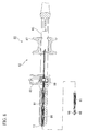
- FIG. 1 is an overall summary view of a high frequency forceps according to a first embodiment of the present invention.
- FIG. 2 is a side view of primary parts of a high frequency forceps according to a first embodiment of the present invention.
- FIG. 3 is an overall summary view of a high frequency forceps according to a second embodiment of the present invention.
- FIG. 4 is a partial cross-sectional plan view of primary parts of a papillotomy knife according to a third embodiment of the present invention.
- FIG. 5 is a partial cross-sectional plan view of primary parts of a high frequency knife according to a fourth embodiment of the present invention.
- FIG. 6 is a partial cross-sectional plan view of primary parts of a high frequency snare according to a fifth embodiment of the present invention.
- FIG. 7 is an overall summary view of a high frequency forceps according to a sixth embodiment of the present invention.
- FIG. 8 is a partial cross-sectional plan view of primary parts of a high frequency forceps according to a seventh embodiment of the present invention.
- FIG. 9 is a partial cross-sectional plan view of primary parts of a high frequency forceps according to a seventh embodiment of the present invention.
- FIG. 10A is a side view of primary parts of a high frequency forceps according to an eighth embodiment of the invention.
- FIG. 10B is a plan view of primary parts of a high frequency forceps according to an eighth embodiment of the invention.
- A first embodiment of the invention will be explained with reference to FIG.S. 1 and 2.
- A high frequency forceps (high frequency treatment instrument) 1 according to the present invention includes an electrical circuit 7 which is connected via a
connection cord 3 to a highfrequency power source 2 which generates a high frequency voltage in which a pair of forceps pieces (treatment electrodes) 6A and 6B which performs conduction treatment to a target tissue S by using high frequency current between a return electrode 5 with the high frequency voltage applied from the highfrequency power source 2, and is known as a monopolar high frequency forceps. The high frequency forceps includes an elongatedflexible tube 8 in which the pair offorceps pieces operation part 10 for opening and closing the pair offorceps pieces part 11 that is connected to the electrical circuit 7 and, based on the frequency of the highfrequency power source 2, changes at least one of an actual number part and an imaginary number part of the impedance of the electrical circuit 7. - The
flexible tube 8 includes a stainlesssteel coil sheath 12 and a resinouter sheath 13 that covers an outer side of thecoil sheath 12 in whichoperation wires flexible tube 8. Asupport part 16 is connected to the distal end of thecoil sheath 12 to which the pair offorceps pieces forceps pieces operation wires support part 16. - The
operation part 10 includes anoperation part body 17 to which the proximal end of theflexible tube 8 is connected, and aslider 18 which is disposed so as to advance and retreat with respect to theoperation part body 17. In theslider 18, anelectrode terminal 20 to which aconnection cord 3 is connected is disposed, and proximal ends of theoperation wires slider 18 via awire attachment part 21. - The impedance adjust
part 11 includes acapacitor part 22 whose capacitance is set to a predetermined value so as to minimize the impedance of the electrical circuit 7. The capacitance of thecapacitor part 22 is based on the value of the impedance when a predetermined high frequency current is supplied to the electrical circuit 7, which is formed when theelectrode terminal 20 and the highfrequency power source 2 are connected via theconnection cord 3 with respect to a high frequency forceps without the impedance adjustpart 11 and when the target tissue S is clasped by the pair offorceps pieces part 11 is connected in series to the electrical circuit 7. In the embodiment as shown in F. 2, it is connected in series to theelectrode terminal 20. - The capacitor part may have a capacitance that is determined based on the impedance of an electrical circuit formed by connecting the
electrode terminal 20 and the highfrequency power source 2 via theconnection cord 3 without clasping the target tissue S. Alternatively, it may have a capacitance that is determined based on an electrical circuit of a high frequency forceps single unit formed from the pair offorceps pieces operation wires electrode terminal 20. - Subsequently, a function of the
high frequency forceps 1 will be described. - Without attaching the impedance adjust
part 11, theelectrode terminal 20 and the highfrequency power source 2 are connected via theconnection cord 3, and a material having similar impedance as the target tissue S is mounted on the return plate 5. Theslider 18 is then retreated from theoperation part body 17 and clasped by the pair offorceps pieces - Equation (1) expresses the magnitude (|Z0 |Ω) when the impedance at this time is Z0. Here, R0, L0, and C0 respectively represent the resistance (Ω), the inductance (H), and the capacitance (F) of an existing electrical circuit, while f represents the frequency of the high frequency current.

- Subsequently, based on the magnitude of the measured impedance, when the impedance adjust
part 11 is connected in series, a capacitance (C1) which minimizes a portion relating to the square of the imaginary number part of the equation (1) is calculated. An impedance adjustpart 11 which includes acapacitor part 22 whose capacitance satisfies this capacitance (C1) is connected in series to theelectrode terminal 20. The impedance adjustpart 11 can be connected after measuring the impedance at that point, or an impedance adjustpart 11 that is designed based on an impedance ascertained beforehand can be assembled in a manufacturing process of thehigh frequency forceps 1. - An endoscope having an unillustrated treatment instrument channel is inserted into a test body where the return plate 5 is placed, and a distal end part of the endoscope is disposed near the target tissue S. The
flexible tube 8 of thehigh frequency forceps 1 including the impedance adjustpart 11 is then inserted into the channel, and is protruded from the channel towards the target tissue S. - The
high frequency forceps 1 and the highfrequency power source 2 are connected using theconnection cord 3, theslider 18 is retreated with respect to theoperation part body 17, and the target tissue S is clasped by the pair offorceps pieces - The magnitude (Z1) of the impedance of the
high frequency forceps 1 is a value expressed by equation (2).
- In this case, since this minimizes a portion relating to the square of the imaginary number part of the impedance in the state where the impedance adjust
part 11 is connected to the electrical circuit 7, a large part of the magnitude of the impedance can be constituted of only the resistance component. The target tissue S clasped by the pair offorceps pieces - According to the
high frequency forceps 1, since the impedance adjustpart 11 minimizes the imaginary part of the impedance of the electrical circuit, high frequency current can be efficiently supplied and power consumption can be reduced. Depending on the measurement of the impedance, an unillustrated coil part whose inductance is set to a predetermined value can be used instead of thecapacitor part 22. - This similarly minimizes the portion of the equation (2) relating to the square of the imaginary number part of the impedance of the electrical circuit, enabling a large part of the magnitude of the impedance to be constituted of only the resistance component.
- Subsequently, a second embodiment will be explained with reference to FIG 3.
- Constituent components identical with those of the first embodiment are denoted with the same reference numerals, and identical descriptions will be omitted.
- The second embodiment differs from the first embodiment in that an impedance adjust
part 31 of ahigh frequency forceps 30 according to the embodiment further includes an unillustrated electrical resistor part. - The electrical resistor part changes the value of the actual number part of the impedance of the electrical circuit. The resistance value of the electrical resistor part is based on the resistance value of the electrical circuit which is formed when the
electrode terminal 20 and the highfrequency power source 2 are connected via theconnection cord 3 to a high frequency forceps without the impedance adjustpart 31 and when the target tissue S is clasped by the pair offorceps pieces frequency power source 2 is below a proximity of rating, the resistance value of the overall electrical circuit 7 when the impedance adjustpart 31 is connected is set so as to be increased. The impedance adjustpart 31 is connected in series with the electrical circuit in the same manner as the first embodiment. - Subsequently, a function of the
high frequency forceps 30 according to the embodiment will be explained. - As in the first embodiment, without attaching the impedance adjust
part 31 with a high frequency current having a predetermined frequency being supplied, the impedance of the overall electrical circuit is measured. - At this time, for example, when the output of the high
frequency power source 2 falls below a proximity of rating, the resistance value needed to raise the output to the proximity of rating is calculated. Based on the magnitude of the measured impedance, an impedance adjustpart 31 whose resistance value is adjusted so as to reflect the actual number part in the equation (1) is connected in series to theelectrode terminal 20. - The
flexible tube 8 of thehigh frequency forceps 30 including the impedance adjustpart 31 is then inserted into the channel, the target tissue S is clasped by the pair offorceps pieces part 31 is connected to the electrical circuit 7 is the resistance value at the proximity of rating output, the target tissue S clasped by the pair offorceps pieces - According to the
high frequency forceps 30, even if the impedance when thehigh frequency forceps 30 is connected is too low with respect to the load characteristics of the highfrequency power source 2, sufficient power in respect of the load characteristics of the high frequency power source can be output. - Subsequently, a third embodiment will be explained with reference to FIG. 4.
- Constituent components identical with those of the other embodiment described above are denoted with the same reference numerals, and identical descriptions will be omitted.
- The third embodiment differs from the first embodiment in that a high frequency treatment instrument according to the embodiment is a
papillotomy knife 40. - A knife (treatment electrode) 42 is connected to a distal end of an
operation wire 41. A distal end of theknife 42 is connected to a distalend securing part 43 for securing the distal end of theknife 42. Aflexible tube 45 includes aresin sheath 46 in which holes 46a and 46b for exposing theknife 42 to the outside are provided in the distal end thereof. - An
operation part 47 includes anoperation part body 48 to which a proximal end of thesheath 46 is connected, and aslider 49 which can advance and retreat with respect to theoperation part body 48. Theslider 49 is provided with anelectrode terminal 20 to which an unillustrated impedance adjust part, similar to the impedance adjustpart 11 of the first embodiment, is connected in series. As in the first embodiment, theelectrode terminal 20 and theoperation wire 41 are connected. - According to the
papillotomy knife 40, since an impedance adjust part similar to the impedance adjustpart 11 of the first embodiment is provided, when a high frequency current at a predetermined frequency is supplied, similar effects to those of thehigh frequency forceps 1 according to the first embodiment can be obtained. - Subsequently, a fourth embodiment will be explained with reference to FIG. 5.
- Constituent components identical with those of the other embodiment described above are denoted with the same reference numerals, and identical descriptions will be omitted.
- The fourth embodiment differs from the third embodiment in that a high frequency treatment instrument according to this embodiment is a
high frequency knife 50. - A knife for electrode (treatment electrode) 52 is connected to a distal end of an
operation wire 51 via astopper support part 53. A stopper member 5 7 is provided at a distal end of aflexible tube 56 in order to regulate the knife for electrode so that it does not protrude more than a predetermined length. Anoperation part 58 is provided with anelectrode terminal 20 to which an unillustrated impedance adjust part, similar to the impedance adjustpart 11 of the first embodiment, is connected in series. - According to the
high frequency knife 52, since an impedance adjust part similar to the impedance adjustpart 11 of the first embodiment is provided, when a high frequency current at a predetermined frequency is supplied, similar effects to those of thehigh frequency forceps 1 can be obtained. - Subsequently, a fifth embodiment will be explained with reference to FIG. 6.
- Constituent components identical with those of the other embodiment described above are denoted with the same reference numerals, and identical descriptions will be omitted.
- The fifth embodiment differs from the first embodiment in that a high frequency treatment instrument according to this embodiment is a
high frequency snare 60. - A snare loop (treatment electrode) 62, which is formed of a looped
elastic wire 62a, is connected to a distal end of anoperation wire 61. - A
flexible tube 66 is provided with only asheath 67, which is different from the first embodiment, and an operation wire is disposed inside thesheath 67 so as to advance and retreat. Anoperation part 10 is provided with anelectrode terminal 20 to which an unillustrated impedance adjust part, similar to the impedance adjustpart 11 of the first embodiment, is connected in series. - According to the
high frequency snare 60, since an impedance adjust part similar to the impedance adjustpart 11 of the first embodiment is provided, when a high frequency current at a predetermined frequency is supplied, similar effects to those of thehigh frequency forceps 1 according to the first embodiment can be obtained. - Subsequently, a sixth embodiment will be explained with reference to FIG 7.
- Constituent components identical with those of the other embodiment described above are denoted with the same reference numerals, and identical descriptions will be omitted.
- The sixth embodiment differs from the first embodiment in that a high frequency forceps (treatment instrument) 70 according to this embodiment is a bipolar type.
- Unillustrated operation wires are arranged inside a
flexible tube 71 in mutually insulated state, and connected to anelectrode terminal 72 in the insulated state. Theelectrode terminal 72 is constituted separately for positive pole and negative pole. As in the first embodiment, an impedance adjustpart 73 is connected in series to theelectrode terminal 72. A first forceps piece (first electrode) 75A and a second forceps piece (second electrode) 75B, which generate mutually different potential differences, are respectively connected to distal ends of the operation wires. Accordingly,connection cords first forceps piece 75A and thesecond forceps piece 75B respectively. - Subsequently, a function of the
high frequency forceps 70 according to the embodiment will be explained. - First, without attaching the impedance adjust
part 73, theelectrode terminal 72 and the highfrequency power source 2 are connected via theconnection cords slider 77 is retreated with respect to theoperation part body 78, and a material having the same impedance as the target tissue S is clasped by thefirst forceps piece 75A and thesecond forceps piece 75B. Without attaching the impedance adjustpart 73, a high frequency current at a predetermined high frequency is supplied and the impedance of the overall electrical circuit is measured. - As in the first embodiment, based on the magnitude of the measured impedance, the impedance adjust
part 73 including an unillustrated capacitor part having a capacitance which is equal to the capacitance (C1) in the equation (2) is connected in series to theelectrode terminal 20. - The
flexible tube 71 of thehigh frequency forceps 70 including the impedance adjustpart 73 is then inserted into the channel, the target tissue S is clasped by thefirst forceps piece 75A and thesecond forceps piece 75B, and a high frequency current having a predetermined frequency is supplied. Since this minimizes the portion relating to the square of the imaginary number part of the impedance in the state where the impedance adjustpart 73 is connected to the electrical circuit, a large part of the magnitude of the impedance becomes only the resistance component. Thus the target tissue S clasped by thefirst forceps piece 75A and thesecond forceps piece 75B is cauterized, and operations such as stopping bleeding and dissection are performed. - According to the
high frequency forceps 70, similar effects to those of the first embodiment can be obtained. - Subsequently, a seventh embodiment will be explained with reference to FIGS. 8 and 9.
- Constituent components identical with those of the other embodiment described above are denoted with the same reference numerals, and identical descriptions will be omitted.
- The seventh embodiment differs from the first embodiment in that a
coil sheath 81 of ahigh frequency forceps 80 according to the embodiment is an impedance adjust part. - The
coil sheath 81 is formed by winding wire formed of a material with a low resistance value such as tungsten or molybdenum. The diameter and winding number of thecoil sheath 81 is adjusted such that, when a high frequency current having a predetermined frequency is supplied, such an inductance that a portion relating to the square of the imaginary number part of the impedance of the electrical circuit becomes minimized is provided. - An
operation part 82 includes anoperation part body 85 including aconnection part 83 in which theelectrode terminal 20 is provided, and aslider 87 to which a proximal end of anoperation wire 86 is connected. Theconnection part 83 is provided with acoil attachment part 88 for connecting the proximal end of thecoil sheath 81 to theelectrode terminal 20. - Subsequently, a function of the
high frequency forceps 80 according to the embodiment will be explained. - First, the
electrode terminal 20 and the highfrequency power source 2 are connected via theconnection cord 3, and a material having similar impedance as the target tissue S is mounted on the return plate 5. Theslider 87 is then retreated with respect to theoperation part body 85 and clasped by the pair offorceps pieces - Based on the magnitude of the measured impedance, an inductance of the electrical circuit that minimizes the portion relating to the square of the imaginary number part of the equation (1) is calculated. The diameter and winding number of the
coil sheath 81 are respectively changed to predetermined values to satisfy the inductance. The diameter and winding number of thecoil sheath 81 can respectively be changed to predetermined values after measuring the impedance at that point, or acoil sheath 81 that is designed based on an impedance ascertained beforehand can be assembled in a manufacturing process of thehigh frequency forceps 80. - Thereafter, a high frequency current having a predetermined frequency is supplied by an operation similar to that of the first embodiment.
- According to the
high frequency forceps 80, thecoil sheath 81 can be used as an impedance adjust part for adjusting the inductance by changing the diameter, material, and winding number of thecoil sheath 81. Therefore, the high frequency forceps structure can be simplified without adding new members. - Subsequently, an eighth embodiment will be explained with reference to FIG 10.
- Constituent components identical with those of the other embodiment described above are denoted with the same reference numerals, and identical descriptions will be omitted.
- The eighth embodiment differs from the first embodiment in that an
operation wire 91 of ahigh frequency forceps 90 according to the embodiment includes an insulatingcore wire member 91 a, and a side wire member 9 1 b that is wound around thecore wire member 91 a, theoperation wire 91 functioning as impedance adjust part. - The
side wire member 91 b is formed of a material with a low resistance value such as tungsten or molybdenum. The diameter and winding number of theside wire member 91 b and the diameter of thecore member 91 a are adjusted such that, when a high frequency current having a predetermined frequency is supplied to theoperation wire 91, such an inductance that the portion relating to the square of the imaginary number part of the impedance of the electrical circuit becomes minimized is provided. - Subsequently, a function of the
high frequency forceps 90 according to the embodiment will be explained. - First, as in the first embodiment, a high frequency current having a predetermined frequency is supplied and the impedance of the overall electrical circuit is measured.
- Based on the magnitude of the measured impedance, an inductance that minimizes the portion relating to the square of the imaginary number part of the equation (1) is calculated. The diameter and winding number of the
side wire member 91b and the diameter of thecore member 91a are adjusted so as to satisfy the inductance. - Thereafter, a high frequency current having a predetermined frequency is supplied by an operation similar to that of the first embodiment.
- According to the
high frequency forceps 90, theoperation wire 91 functions as an impedance adjust part which is able to adjust the iuductance by changing the diameter, material quality, and winding number of theside wire member 91b of theoperation wire 91. - Therefore, the high frequency forceps structure can be simplified without adding new members.
- The technical field of the present invention is not limited to the embodiments described and illustrated above; it is possible to make various modifications without departing from the spirit or scope of the present invention.
- For example, in the first embodiment, the impedance adjust
part 11 is connected in series with theelectrode terminal 20 because it has a specific configuration for each treatment instrument, however, there is no limitation on this, and it can, for example, be connected in series to a connector portion of a general-purpose connection cord. - Also, depending on the impedance measurement result, the impedance adjust part can include a coil part, a capacitor part, and an electrical resistor part, each of which is independently provided; alternatively, it can be configured by a combination of at least two of these.
- Moreover, the capacitance, inductance, and resistance of the impedance adjust part can be made changeable even after the impedance adjust part is connected.
Claims (9)
- A high frequency treatment instrument comprising an electrical circuit which is connected to a high frequency power source which generates a high frequency voltage in which at least one treatment electrode is included for performing conduction treatment using a high frequency current to a target tissue by applying a high frequency voltage from the high frequency power source, wherein
the high frequency treatment instrument comprising:an impedance adjust part which is connected to the electrical circuit and based on the frequency of the high frequency power source changes at least one of an actual number part and an imaginary number part of an impedance of the electrical circuit. - The high frequency treatment instrument according to claim 1, wherein the impedance adjust part changes the impedance of the electrical circuit when the high frequency power source and the treatment electrode are made conductive.
- The high frequency treatment instrument according to claim 2, wherein the impedance adjust part changes the impedance of the electrical circuit when the treatment electrode contacts the target tissue.
- The high frequency treatment instrument according to any one of claims 1 to 3, wherein the impedance adjust part includes a coil part having an inductance or a capacitor having a capacitance, and is connected is series with the electrical circuit.
- The high frequency treatment instrument according to claim 3, wherein the impedance adjust part includes an electrical resistor, and is connected in series with the electrical circuit.
- The high frequency treatment instrument according to claim 4, wherein the treatment electrode includes an elongated coil sheath connected to a distal end thereof; and the coil sheath constitutes the coil part.
- The high frequency treatment instrument according to any one of claims 1 to 3 and claims 5 to 6, wherein the treatment electrode includes a first electrode and a second electrode which create mutually different potential differences.
- The high frequency treatment instrument according to claim 4, wherein the treatment electrode includes a first electrode and a second electrode which create mutually different potential differences.
- A high frequency treatment instrument comprising an electrical circuit which is connected to a high frequency power source which generates a high frequency voltage in which at least one treatment electrode is included for performing conduction treatment using a high frequency current to a target tissue by applying a high frequency voltage from the high frequency power source, further comprising
an impedance adjust part which is connected to the electrical circuit, and is set such that the magnitude of the impedance of the electrical circuit is minimized with respect to the frequency of the high frequency power source.
Applications Claiming Priority (1)
| Application Number | Priority Date | Filing Date | Title |
|---|---|---|---|
| JP2006164630A JP4611247B2 (en) | 2006-06-14 | 2006-06-14 | High frequency treatment tool |
Publications (2)
| Publication Number | Publication Date |
|---|---|
| EP1867296A1 true EP1867296A1 (en) | 2007-12-19 |
| EP1867296B1 EP1867296B1 (en) | 2019-01-16 |
Family
ID=38477264
Family Applications (1)
| Application Number | Title | Priority Date | Filing Date |
|---|---|---|---|
| EP07011488.9A Ceased EP1867296B1 (en) | 2006-06-14 | 2007-06-12 | High frequency treatment instrument |
Country Status (3)
| Country | Link |
|---|---|
| US (1) | US20080125769A1 (en) |
| EP (1) | EP1867296B1 (en) |
| JP (1) | JP4611247B2 (en) |
Cited By (2)
| Publication number | Priority date | Publication date | Assignee | Title |
|---|---|---|---|---|
| EP2147650A1 (en) * | 2008-07-23 | 2010-01-27 | Olympus Medical Systems Corp. | High-frequency treatment instrument |
| CN104619274A (en) * | 2012-11-13 | 2015-05-13 | 奥林巴斯医疗株式会社 | Treatment tool for endoscope |
Families Citing this family (5)
| Publication number | Priority date | Publication date | Assignee | Title |
|---|---|---|---|---|
| US8469993B2 (en) | 2003-06-18 | 2013-06-25 | Boston Scientific Scimed, Inc. | Endoscopic instruments |
| US20040260337A1 (en) | 2003-06-18 | 2004-12-23 | Scimed Life Systems, Inc. | Endoscopic instruments and methods of manufacture |
| US7951165B2 (en) | 2003-08-18 | 2011-05-31 | Boston Scientific Scimed, Inc. | Endoscopic medical instrument and related methods of use |
| US7762960B2 (en) | 2005-05-13 | 2010-07-27 | Boston Scientific Scimed, Inc. | Biopsy forceps assemblies |
| JP5171471B2 (en) * | 2008-08-08 | 2013-03-27 | オリンパスメディカルシステムズ株式会社 | Endoscopic treatment tool |
Citations (4)
| Publication number | Priority date | Publication date | Assignee | Title |
|---|---|---|---|---|
| US4615330A (en) * | 1983-09-05 | 1986-10-07 | Olympus Optical Co., Ltd. | Noise suppressor for electronic endoscope |
| WO2001015617A1 (en) * | 1999-09-01 | 2001-03-08 | Michael Douglas Spears | Tool and method for cutting powered by an electromagnetic (em) source |
| JP2005058344A (en) | 2003-08-08 | 2005-03-10 | Olympus Corp | Hemostatic forceps for endoscope |
| EP1743589A2 (en) | 2005-06-21 | 2007-01-17 | Olympus Medical Systems Corp. | High-frequency treatment instrument |
Family Cites Families (18)
| Publication number | Priority date | Publication date | Assignee | Title |
|---|---|---|---|---|
| US3999552A (en) * | 1975-05-20 | 1976-12-28 | Universal Technology, Inc. | Epilator |
| JPS55116345A (en) * | 1979-03-02 | 1980-09-06 | Olympus Optical Co | Highhfrequency cutting appliance |
| US4945912A (en) * | 1988-11-25 | 1990-08-07 | Sensor Electronics, Inc. | Catheter with radiofrequency heating applicator |
| JPH0332661A (en) * | 1989-06-29 | 1991-02-13 | Sunstar Inc | Electric surgical operation device |
| US5697909A (en) * | 1992-01-07 | 1997-12-16 | Arthrocare Corporation | Methods and apparatus for surgical cutting |
| US5445635A (en) * | 1992-05-01 | 1995-08-29 | Hemostatic Surgery Corporation | Regulated-current power supply and methods for resistively-heated surgical instruments |
| US5964759A (en) * | 1992-10-27 | 1999-10-12 | Ortho Development Corporation | Electroconvergent cautery system |
| GB9314391D0 (en) * | 1993-07-12 | 1993-08-25 | Gyrus Medical Ltd | A radio frequency oscillator and an electrosurgical generator incorporating such an oscillator |
| GB9708268D0 (en) * | 1997-04-24 | 1997-06-18 | Gyrus Medical Ltd | An electrosurgical instrument |
| JP3068052B2 (en) * | 1998-04-06 | 2000-07-24 | 株式会社メックス | Electrosurgical equipment |
| JP2000333970A (en) * | 1999-05-31 | 2000-12-05 | Nippon Zeon Co Ltd | Bipolar medical electrical treatment instrument |
| US6692489B1 (en) * | 1999-07-21 | 2004-02-17 | Team Medical, Llc | Electrosurgical mode conversion system |
| AU2002952318A0 (en) * | 2002-10-29 | 2002-11-14 | Advanced Metal Coatings Pty Limited | Production of lesions in a body |
| JP4137610B2 (en) * | 2002-11-25 | 2008-08-20 | オリンパス株式会社 | Incision tool |
| ATE398974T1 (en) * | 2002-11-27 | 2008-07-15 | Medical Device Innovations Ltd | COAXIAL TISSUE ABLATION SAMPLE AND METHOD FOR PRODUCING A BALANCER THEREOF |
| US7169145B2 (en) * | 2003-11-21 | 2007-01-30 | Megadyne Medical Products, Inc. | Tuned return electrode with matching inductor |
| WO2005115235A1 (en) * | 2004-05-26 | 2005-12-08 | Medical Device Innovations Limited | Tissue detection and ablation apparatus and apparatus and method for actuating a tuner |
| US7957815B2 (en) * | 2005-10-11 | 2011-06-07 | Thermage, Inc. | Electrode assembly and handpiece with adjustable system impedance, and methods of operating an energy-based medical system to treat tissue |
-
2006
- 2006-06-14 JP JP2006164630A patent/JP4611247B2/en not_active Expired - Fee Related
-
2007
- 2007-06-11 US US11/811,584 patent/US20080125769A1/en not_active Abandoned
- 2007-06-12 EP EP07011488.9A patent/EP1867296B1/en not_active Ceased
Patent Citations (4)
| Publication number | Priority date | Publication date | Assignee | Title |
|---|---|---|---|---|
| US4615330A (en) * | 1983-09-05 | 1986-10-07 | Olympus Optical Co., Ltd. | Noise suppressor for electronic endoscope |
| WO2001015617A1 (en) * | 1999-09-01 | 2001-03-08 | Michael Douglas Spears | Tool and method for cutting powered by an electromagnetic (em) source |
| JP2005058344A (en) | 2003-08-08 | 2005-03-10 | Olympus Corp | Hemostatic forceps for endoscope |
| EP1743589A2 (en) | 2005-06-21 | 2007-01-17 | Olympus Medical Systems Corp. | High-frequency treatment instrument |
Cited By (3)
| Publication number | Priority date | Publication date | Assignee | Title |
|---|---|---|---|---|
| EP2147650A1 (en) * | 2008-07-23 | 2010-01-27 | Olympus Medical Systems Corp. | High-frequency treatment instrument |
| CN101632602B (en) * | 2008-07-23 | 2011-06-15 | 奥林巴斯医疗株式会社 | High-frequency treatment instrument |
| CN104619274A (en) * | 2012-11-13 | 2015-05-13 | 奥林巴斯医疗株式会社 | Treatment tool for endoscope |
Also Published As
| Publication number | Publication date |
|---|---|
| JP2007330436A (en) | 2007-12-27 |
| US20080125769A1 (en) | 2008-05-29 |
| JP4611247B2 (en) | 2011-01-12 |
| EP1867296B1 (en) | 2019-01-16 |
Similar Documents
| Publication | Publication Date | Title |
|---|---|---|
| EP1867296A1 (en) | High frequency treatment instrument | |
| AU2009213017B2 (en) | Electrosurgical apparatus with high speed energy recovery | |
| AU2009212983B2 (en) | Electrosurgical apparatus with high speed energy recovery | |
| EP1728462A3 (en) | Instrument for endoscope and instrument system for endoscope | |
| CN105263557A (en) | An electrical lead for a catheter and method of manufacturing | |
| CN104519820B (en) | Electrosurgical Instruments and Systems | |
| JP2023523858A (en) | Electrode assembly for endoscopic surgery | |
| ES2184609A1 (en) | Method and apparatus for obtaining physical and/or chemical characteristics of a biological medium | |
| US20030088302A1 (en) | Living body insertion electrode lead, and living body insertion medical instrument using the same | |
| US9375257B2 (en) | High-frequency treatment instrument | |
| JP6157633B2 (en) | Bipolar coagulation and cutting electrodes | |
| US11510726B2 (en) | Bipolar electrosurgical instruments | |
| JP2019020369A (en) | Current sensor and measurement device | |
| EP3056159B1 (en) | Medical device | |
| JP2004008243A (en) | Electrode instrument for microwave surgery | |
| JP7226739B2 (en) | Endoscope Microwave Irradiator | |
| JP7271948B2 (en) | Forceps-type instrument | |
| JP2006047111A (en) | Shunt for current measurement | |
| EP3666206A1 (en) | Indifferent electrode with selectable area | |
| JP2002306506A (en) | Bipolar high frequency treatment tool for endoscope | |
| CN219166621U (en) | Novel bipolar coagulation forceps handle | |
| WO2006134483A3 (en) | Handpiece for an electronic scalpel for use in mni-invasive spinal surgery | |
| JP2012016610A (en) | High-frequency treatment device | |
| JP2002330978A (en) | Bipolar high frequency treatment tool for endoscope | |
| RU89713U1 (en) | DEVICE FOR ELECTRICAL STIMULATION OF BIOLOGICAL OBJECTS |
Legal Events
| Date | Code | Title | Description |
|---|---|---|---|
| PUAI | Public reference made under article 153(3) epc to a published international application that has entered the european phase |
Free format text: ORIGINAL CODE: 0009012 |
|
| AK | Designated contracting states |
Kind code of ref document: A1 Designated state(s): AT BE BG CH CY CZ DE DK EE ES FI FR GB GR HU IE IS IT LI LT LU LV MC MT NL PL PT RO SE SI SK TR |
|
| AX | Request for extension of the european patent |
Extension state: AL BA HR MK YU |
|
| 17P | Request for examination filed |
Effective date: 20080226 |
|
| 17Q | First examination report despatched |
Effective date: 20080417 |
|
| AKX | Designation fees paid |
Designated state(s): DE FR GB IE |
|
| RAP1 | Party data changed (applicant data changed or rights of an application transferred) |
Owner name: OLYMPUS CORPORATION |
|
| RAP1 | Party data changed (applicant data changed or rights of an application transferred) |
Owner name: OLYMPUS CORPORATION |
|
| RAP1 | Party data changed (applicant data changed or rights of an application transferred) |
Owner name: OLYMPUS CORPORATION |
|
| RIN1 | Information on inventor provided before grant (corrected) |
Inventor name: SUZUKI, KEITA Inventor name: KIMURA, MEGUMI |
|
| GRAP | Despatch of communication of intention to grant a patent |
Free format text: ORIGINAL CODE: EPIDOSNIGR1 |
|
| INTG | Intention to grant announced |
Effective date: 20180820 |
|
| GRAS | Grant fee paid |
Free format text: ORIGINAL CODE: EPIDOSNIGR3 |
|
| GRAA | (expected) grant |
Free format text: ORIGINAL CODE: 0009210 |
|
| AK | Designated contracting states |
Kind code of ref document: B1 Designated state(s): DE FR GB IE |
|
| REG | Reference to a national code |
Ref country code: GB Ref legal event code: FG4D |
|
| REG | Reference to a national code |
Ref country code: IE Ref legal event code: FG4D |
|
| REG | Reference to a national code |
Ref country code: DE Ref legal event code: R096 Ref document number: 602007057422 Country of ref document: DE |
|
| REG | Reference to a national code |
Ref country code: DE Ref legal event code: R097 Ref document number: 602007057422 Country of ref document: DE |
|
| PLBE | No opposition filed within time limit |
Free format text: ORIGINAL CODE: 0009261 |
|
| STAA | Information on the status of an ep patent application or granted ep patent |
Free format text: STATUS: NO OPPOSITION FILED WITHIN TIME LIMIT |
|
| 26N | No opposition filed |
Effective date: 20191017 |
|
| GBPC | Gb: european patent ceased through non-payment of renewal fee |
Effective date: 20190612 |
|
| PG25 | Lapsed in a contracting state [announced via postgrant information from national office to epo] |
Ref country code: GB Free format text: LAPSE BECAUSE OF NON-PAYMENT OF DUE FEES Effective date: 20190612 Ref country code: IE Free format text: LAPSE BECAUSE OF NON-PAYMENT OF DUE FEES Effective date: 20190612 |
|
| PG25 | Lapsed in a contracting state [announced via postgrant information from national office to epo] |
Ref country code: FR Free format text: LAPSE BECAUSE OF NON-PAYMENT OF DUE FEES Effective date: 20190630 |
|
| PGFP | Annual fee paid to national office [announced via postgrant information from national office to epo] |
Ref country code: DE Payment date: 20220620 Year of fee payment: 16 |
|
| REG | Reference to a national code |
Ref country code: DE Ref legal event code: R119 Ref document number: 602007057422 Country of ref document: DE |
|
| PG25 | Lapsed in a contracting state [announced via postgrant information from national office to epo] |
Ref country code: DE Free format text: LAPSE BECAUSE OF NON-PAYMENT OF DUE FEES Effective date: 20240103 |