EP1867280A1 - System for acquiring information on inside of subject - Google Patents
System for acquiring information on inside of subject Download PDFInfo
- Publication number
- EP1867280A1 EP1867280A1 EP06731287A EP06731287A EP1867280A1 EP 1867280 A1 EP1867280 A1 EP 1867280A1 EP 06731287 A EP06731287 A EP 06731287A EP 06731287 A EP06731287 A EP 06731287A EP 1867280 A1 EP1867280 A1 EP 1867280A1
- Authority
- EP
- European Patent Office
- Prior art keywords
- information
- intra
- unit
- receiving apparatus
- subject
- Prior art date
- Legal status (The legal status is an assumption and is not a legal conclusion. Google has not performed a legal analysis and makes no representation as to the accuracy of the status listed.)
- Withdrawn
Links
Images




Classifications
-
- A—HUMAN NECESSITIES
- A61—MEDICAL OR VETERINARY SCIENCE; HYGIENE
- A61B—DIAGNOSIS; SURGERY; IDENTIFICATION
- A61B1/00—Instruments for performing medical examinations of the interior of cavities or tubes of the body by visual or photographical inspection, e.g. endoscopes; Illuminating arrangements therefor
-
- A—HUMAN NECESSITIES
- A61—MEDICAL OR VETERINARY SCIENCE; HYGIENE
- A61B—DIAGNOSIS; SURGERY; IDENTIFICATION
- A61B1/00—Instruments for performing medical examinations of the interior of cavities or tubes of the body by visual or photographical inspection, e.g. endoscopes; Illuminating arrangements therefor
- A61B1/00002—Operational features of endoscopes
- A61B1/00011—Operational features of endoscopes characterised by signal transmission
- A61B1/00016—Operational features of endoscopes characterised by signal transmission using wireless means
-
- A—HUMAN NECESSITIES
- A61—MEDICAL OR VETERINARY SCIENCE; HYGIENE
- A61B—DIAGNOSIS; SURGERY; IDENTIFICATION
- A61B1/00—Instruments for performing medical examinations of the interior of cavities or tubes of the body by visual or photographical inspection, e.g. endoscopes; Illuminating arrangements therefor
- A61B1/00002—Operational features of endoscopes
- A61B1/00025—Operational features of endoscopes characterised by power management
- A61B1/00036—Means for power saving, e.g. sleeping mode
-
- A—HUMAN NECESSITIES
- A61—MEDICAL OR VETERINARY SCIENCE; HYGIENE
- A61B—DIAGNOSIS; SURGERY; IDENTIFICATION
- A61B1/00—Instruments for performing medical examinations of the interior of cavities or tubes of the body by visual or photographical inspection, e.g. endoscopes; Illuminating arrangements therefor
- A61B1/00002—Operational features of endoscopes
- A61B1/00043—Operational features of endoscopes provided with output arrangements
- A61B1/00045—Display arrangement
-
- A—HUMAN NECESSITIES
- A61—MEDICAL OR VETERINARY SCIENCE; HYGIENE
- A61B—DIAGNOSIS; SURGERY; IDENTIFICATION
- A61B1/00—Instruments for performing medical examinations of the interior of cavities or tubes of the body by visual or photographical inspection, e.g. endoscopes; Illuminating arrangements therefor
- A61B1/04—Instruments for performing medical examinations of the interior of cavities or tubes of the body by visual or photographical inspection, e.g. endoscopes; Illuminating arrangements therefor combined with photographic or television appliances
- A61B1/041—Capsule endoscopes for imaging
-
- A—HUMAN NECESSITIES
- A61—MEDICAL OR VETERINARY SCIENCE; HYGIENE
- A61B—DIAGNOSIS; SURGERY; IDENTIFICATION
- A61B1/00—Instruments for performing medical examinations of the interior of cavities or tubes of the body by visual or photographical inspection, e.g. endoscopes; Illuminating arrangements therefor
- A61B1/00112—Connection or coupling means
- A61B1/00121—Connectors, fasteners and adapters, e.g. on the endoscope handle
- A61B1/00124—Connectors, fasteners and adapters, e.g. on the endoscope handle electrical, e.g. electrical plug-and-socket connection
-
- A—HUMAN NECESSITIES
- A61—MEDICAL OR VETERINARY SCIENCE; HYGIENE
- A61B—DIAGNOSIS; SURGERY; IDENTIFICATION
- A61B2560/00—Constructional details of operational features of apparatus; Accessories for medical measuring apparatus
- A61B2560/02—Operational features
- A61B2560/0204—Operational features of power management
- A61B2560/0209—Operational features of power management adapted for power saving
-
- A—HUMAN NECESSITIES
- A61—MEDICAL OR VETERINARY SCIENCE; HYGIENE
- A61B—DIAGNOSIS; SURGERY; IDENTIFICATION
- A61B5/00—Measuring for diagnostic purposes; Identification of persons
- A61B5/07—Endoradiosondes
- A61B5/073—Intestinal transmitters
Definitions
- the present invention relates to an intra-subject information acquiring system that receives and displays an image signal that is radio transmitted from a body-insertable apparatus, such as a swallowable capsule endoscope, inserted into a subject.
- a body-insertable apparatus such as a swallowable capsule endoscope
- a capsule endoscope having an imaging function and a radio communication function has appeared in the field of endoscope.
- the capsule endoscope is swallowed by a subject from the mouth for an observation (examination), moves within internal organs (within body cavities) such as a stomach and a small intestine, along peristaltic motions thereof, and sequentially images using the imaging function, until naturally discharged from the body (human body).
- image data acquired within the body cavity by the capsule endoscope is sequentially transmitted to the outside of the subject by the radio communication function such as radio communication, and is stored in a memory provided within a receiving apparatus outside.
- the subject carries the receiving apparatus having the radio communication function and the memory function, the subject can move freely even during the observation period after swallowing the capsule endoscope until the capsule endoscope is discharged.
- a doctor or a nurse can perform diagnosis by displaying the images of the body cavity onto a display unit such as a display, based on the image data stored in the memory of the receiving apparatus.
- a receiving apparatus has plural antennas disposed dispersedly at the outside of the subject to receive image signals transmitted from the capsule endoscope, and selectively switches one antenna having a small error in the reception of the image signal to receive the image signal.
- Patent Document 1 describes a receiver that switches between plural antennas disposed at the outside of a subject for reception, and locates a position of a capsule endoscope within the subject as a transmission source of the image signal, based on electric-field strength that each antenna receives.
- Patent Document 1 Japanese Patent Application Laid-open No. 2003-19111
- Some of the receiving apparatuses include a small display device to display a received image signal and position information of a capsule endoscope, and the receiving apparatus itself can be large and heavy.
- the receiving apparatus consumes large power to carry out control of display on the display device, image processing, and calculation of position information.
- some receiving apparatuses are connected to a workstation having a display, and transmits an acquired image signal, position information of a capsule endoscope, or the like to the workstation, so that the information is displayed on the display device. In such as case, the receiving apparatus cannot promptly display the information received from the capsule endoscope.
- an antenna attached to the subject becomes connected to ground, whereby insulation is necessary.
- the present invention has been achieved in view of the above. It is an object of the present invention to provide an intra-subject information acquiring system that can have a small and light receiving apparatus and that can decrease power consumption.
- the present invention provides an intra-subject information acquiring system including a receiving apparatus that receives intra-subject information radio transmitted from a body-insertable apparatus, and a compact display device that takes in and displays the intra-subject information on a display unit
- the intra-subject information acquiring system includes a communication unit that connects between the receiving apparatus and the compact display device in a communicable manner, wherein the receiving apparatus outputs at least the intra-subject information to the compact display device via the communication unit
- the compact display device includes a detector that detects a connection between the compact display device and the receiving apparatus by the communication unit, and a switching controller that switches a display of the display unit to a display of the intra-subject information taken in via the communication unit, based on a result of detection by the detector.
- An intra-subject information acquiring system including a receiving apparatus that receives intra-subject information radio transmitted from a body-insertable apparatus, and a compact display device that takes in and displays the intra-subject information on a display unit
- the intra-subject information acquiring system includes a communication unit that connects between the receiving apparatus and the compact display device in a communicable manner, wherein the receiving apparatus outputs at least the intra-subject information to the compact display device via the communication unit
- the compact display device includes a detector that detects a connection between the compact display device and the receiving apparatus by the communication unit, a radio unit that receives intra-subject information radio transmitted from the body-insertable apparatus, and a switching controller that switch controls a reception operation performed by the radio unit or the communication unit, based on a result of detection by the detector.
- the receiving apparatus further includes a receiving antenna that receives intra-subject information from the body-insertable apparatus, a received strength detector that detects received strength in the receiving antenna, and a superimposing unit that superimposes information of received strength detected by the received strength detector, onto the intra-subject information
- the compact display apparatus further includes an analyzer that analyzes a position of the body-insertable apparatus, based on information of the received strength, and an instructing unit that instructs information displayed on the display unit, and the switching controller switches information displayed on the display unit, according to an instruction of the instructing unit.
- the intra-subject information that the body-insertable apparatus transmits includes at least an image signal acquired by imaging a body cavity of the subject, and position information of the body-insertable apparatus
- the compact display device further includes an instructing unit that instructs information to be displayed on the display unit
- the switching controller switches information displayed on the display unit, according to an instruction of the instructing unit.
- the information displayed on the display unit includes the image signal, information concerning the body-insertable apparatus, information concerning the receiving apparatus, the position information, and information concerning the examination of the subject, and the display unit displays at least one piece of information among these pieces of information, according to a display switching by the switching controller.
- a receiving apparatus and a compact display device are connected via a communication unit.
- the switching controller performs display switching so as to enable the display unit to take in the intra-subject information from the receiving apparatus and to display the intra-subject information. Therefore, the receiving apparatus is not required to be provided with a display unit, and a circuit configuration is simplified, whereby the receiving apparatus can be made compact and light, and power consumption can be decreased.
- the compact display apparatus connected to the receiving apparatus takes in information such as intra-subject information necessary for the examination, and displays the taken-in information on the display unit. Therefore, necessary information such as intra-subject information acquired from a capsule endoscope can be promptly displayed in real time on the display unit.
- FIGS. 1 to 7 Exemplary embodiments of an intra-subject information acquiring system according to the present invention will be explained below in detail with reference to FIGS. 1 to 7. Note that the present invention is not limited to the embodiments, and various modifications of the embodiments can be made without departing from the scope of the present invention.
- FIG. 1 is a schematic diagram showing an overall configuration of an intra-subject information acquiring system according to the present invention.
- a radio intra-subject information acquiring system includes a receiving apparatus 2 having a radio receiving function, and a capsule endoscope (a body-insertable apparatus) 3 that is inserted into a subject 1, picks up images within the body cavity, and transmits data such as an image signal to the receiving apparatus 2.
- the radio intra-subject information acquiring system also includes a viewer 4 as a compact display device that displays a body-cavity image based on an image signal received by the receiving apparatus 2, and a communication cable 5 as a communication unit that delivers data between the receiving apparatus 2 and the viewer 4 as a compact display device.
- the receiving apparatus 2 includes a receiving jacket 2a that the subject 1 wears, and an external device 2b that performs processing of a received radio signal.
- the receiving apparatus 2 has a function of receiving body-cavity image data radio-transmitted from the capsule endoscope 3.
- the receiving apparatus 2 has a shape wearable by the subject 1, and includes the receiving jacket 2a having receiving antennas A1 to An, and the external device 2b that processes a radio signal received via the receiving jacket 2a.
- Each of the receiving antennas A1 to An can be directly adhered to the external surface of the subject (human body) 1 in such a manner that the receiving antennas A1 to An are not attached to the receiving jacket 2a, or can be made detachable from the receiving jacket 2a.
- the external device 2b transmits a received image signal to the viewer 4 as a compact display device via the connected communication cable 5.
- a connector CON is provided on an upper surface of an external surface for the connection to the receiving antennas A1 to An.
- the receiving antennas A1 to An have connectors CON1 to CONn that connect the receiving antennas to the connector CON.
- the external device 2b has a function of binarizing a radio signal transmitted from the capsule endoscope 3 and outputting the resulting signal. In other words, as shown in FIG.
- the external device 2b includes a changeover switch SW that switches a connection of each of the receiving antennas A1 to An, and a tuner 11 that is connected to a latter stage of the changeover switch SW, amplifies a radio signal from the receiving antennas A1 to An of which connection is switched by the changeover switch SW, and demodulates the amplified radio signal.
- a binarizing circuit 12 and a sample-and-hold circuit 15 are connected to the latter stage of the tuner 11.
- An A/D converter 16 is connected to a latter stage of the sample-and-hold circuit 15.
- the superimposing unit 13 has a function of superimposing information from a switching controller SC onto an image signal binarized by the binarizing circuit 12, as a superimposer, and outputting the result to a interface unit 14 connected thereto.
- the switching controller SC has a strength-receiving-antenna number N1, and an image-receiving-antenna number N2, instructs a switching of the changeover switch SW, and instructs a processing timing of the sample-and-hold circuit 15 and the A/D converter 16.
- the interface unit 14 is connected to the communication cable 5 via a connector (not shown).
- the superimposing unit 13 has an internal memory (not shown), and registers identification information that identifies a subject such as an examination ID input from the outside, into the internal memory.
- the superimposing unit 13 superimposes information from the switching controller SC onto the image signal, and outputs the superimposed image signal to the interface unit 14.
- a power supply unit 17 includes a battery embedded in the external device 2b. When a power switch 18 shown in FIG. 3 is turned on, the power supply unit 17 supplies power to each of the above internal devices.
- the changeover switch SW of the external device 2b outputs radio signals from the receiving antennas A1 to An to the tuner 11, based on a switch instruction from the switching controller SC.
- the changeover switch SW has the connector CON as an antenna switch unit that connects each of the receiving antennas A1l to An corresponding to each disposition position of the receiving antennas A1 to An.
- the tuner 11 amplifies a radio signal, outputs a demodulated image signal S1 to the binarizing circuit 12, and outputs a received strength signal S2 as received electric-filed strength of the amplified radio signal, to the sample-and-hold circuit 15.
- the image signal binarized by the binarizing circuit 12 is output to the superimposing unit 13.
- the A/D converter 16 converts the received strength signal that is sampled and held by the sample-and-hold circuit 15, into a digital signal, and the switching controller SC takes in the resulting digital signal.
- the switching controller SC holds the information of a strength-receiving-antenna number N1 and an image-receiving-antenna number N2.
- the switching controller SC outputs to the changeover switch SW a signal S5 that instructs the changeover switch SW to selectively connect one of the receiving antennas A1 to An corresponding to the strength-receiving-antenna number N1, during a strength receiving period, and that instructs the changeover switch SW to selectively connect one of the receiving antennas A1 to An corresponding to the image-receiving-antenna number N2, during an image receiving period.
- the switching controller SC outputs a signal S3a that instructs a sample-and-hold timing of the sample-and-hold circuit 15, and a signal S3b that instructs an A/D conversion timing of the A/D converter 16.
- the switching controller SC also outputs information of one of the receiving antennas A1 to An corresponding to the strength-receiving-antenna number N1 that is taken in during the strength reception period, and information of received strength of each of the receiving antennas A1 to An, to the superimposing unit 13.
- the superimposing unit 13 superimposes the information of the receiving antennas A1 to An corresponding to the strength-receiving-antenna number N1 and the information of the received strength of each of the receiving antennas A1 to An onto the image signal from the binarizing circuit 12, and outputs the superimposed information to the interface unit 14.
- the interface unit 14 transmits the image signal to the viewer 4 as a compact display device via the communication cable 5.
- the superimposing unit 13 according to the present invention can also superimpose the information from the switching controller SC and the identification information registered in the internal memory onto the image signal, and output the superimposed information to the interface unit 14.
- the viewer 4 as a compact display device displays and analyzes the information taken in from the receiving apparatus 2 via the communication cable 5.
- the viewer 4 as a compact display device has a liquid crystal display such as an LCD 41 as a display unit, on the external surface.
- the viewer 4 as a compact display device includes a serial/parallel converter 42 that takes in a signal transmitted from the receiving apparatus 2, and performs serial/parallel conversion on the signal.
- An image signal output from the serial/parallel converter 42 is output to an image processing circuit 43.
- the image data processed by the image processing circuit 43 is output to the LCD 41 via a changeover switch 44, and displayed by the LCD 41.
- a power switch 56 is provided on the external surface of the viewer 4 as a compact display device.
- the communication cable includes a composite cable having a cable that is used to transmit an image signal, and a cable for USB and 232C, and can transmit various kinds of data.
- the information of the receiving antennas A1 to An corresponding to the strength-receiving-antenna number N1 and the information of received strength output from the serial/parallel converter 42 are supplied to the position-information detecting circuit 45.
- the position-information detecting circuit 45 selects a receiving antenna that receives largest received electric-field strength as a receiving antenna, based on the information of the taken-in received strength, and sequentially outputs a number of the selected receiving antenna as position information, to a capsule position analyzer 46.
- the capsule position analyzer 46 analyzes the position of the capsule endoscope 3 within the body cavity of the subject, and outputs information on the result of analysis to a position-information-image generating unit 47.
- the position-information-image generating unit 47 generates and supplies an intra-subject map via the changeover switch 44 to the LCD 41, which displays the intra-subject map together with the position of the capsule endoscope 3 as analyzed by the capsule position analyzer 46.
- the viewer 4 as a compact display device includes a communication-cable connection detector 48, which detects a connection of the communication cable 5 to the receiving apparatus 2.
- a connecting unit 51 of the communication cable 5 includes a contact pin 52 that is electrically connected to a constant voltage source VDD, and a spring 53 that biases the contact pin 52 to push out the contact pin 52 to the outside.
- a projection 22 is provided in a connector 21 of the receiving apparatus at a predetermined position opposing to the contact pin 52 of the connecting unit 51. When the connector 21 is fitted to the connecting unit 51, the projection 22 is brought into contact with the contact pin 52, thereby pressing the contact pin 52 to the inside of the connecting unit 51.
- the contact pin 52 is brought into contact with both an electric path 54 at the constant voltage source VDD side, and an electric path 55 at the side of a control unit 49, and a detection signal is output to the control unit 49.
- the connector 21 is removed from the connecting unit 51, the projection 22 is separated from the contact pin 52, and the contact pin 52 returns to the original position due to the biasing force of the spring 53. Therefore, the contact pin 52 is brought into a non-contact state with the electric path 55 at the control unit 49 side, and the output of a detection signal to the control unit 49 ceases.
- the control unit 49 has a function as a switching unit that switches the display of the LCD 41.
- the control unit 49 switch controls the changeover switch 44, and switches the display of the LCD 41 to the display of information taken in via the communication cable 5.
- An operating unit 50 configured by a display changeover switch and the like of the display unit 41 shown in FIG. 2 is connected to the control unit 49.
- the control unit 49 switch controls the changeover switch 44, based on a display switch instruction of the operating unit 50, selects the information taken in via the communication cable 5, and displays the selected information on the LCD 41.
- the control unit 49 switch controls the changeover switch 44, thereby connecting the image processing circuit 43 with the LCD 41 and displaying the image data on the LCD 44.
- the control unit 49 switch controls the changeover switch 44, based on the instruction, thereby connecting the position-information-image generating unit 47 with the LCD 41, and displaying the intra-subject map generated by the image generating unit 47 and the position of the capsule endoscope 3 on the intra-subject map, on the LCD 44.
- the information displayed on the LCD 41 is not limited to the image data and the position information of the capsule endoscope, and can also include identification information of the subject such as the patient ID mentioned above, a patient name, and age of a patient, information concerning an examination such as a time of examination and an examination ID, information concerning the capsule endoscope such as a capsule ID and remaining battery charge of the capsule, and information concerning the receiving apparatus such as a receiving apparatus ID, a remaining battery charge of the power supply unit 17, a radio signal receiving state, and an alarm issued by the receiving apparatus.
- identification information of the subject such as the patient ID mentioned above, a patient name, and age of a patient
- information concerning an examination such as a time of examination and an examination ID
- information concerning the capsule endoscope such as a capsule ID and remaining battery charge of the capsule
- information concerning the receiving apparatus such as a receiving apparatus ID, a remaining battery charge of the power supply unit 17, a radio signal receiving state, and an alarm issued by the receiving apparatus.
- These pieces of information can be superimposed on the image signal,
- these pieces of information can be registered in an internal memory (not shown) inside the viewer 4 as a compact display device, for example, within an internal memory in the control unit 49, and corresponding information can be made displayed at least on one LCD 41, based on a display switch instruction of the operating unit 50 that can specify a piece of information.
- a display switch instruction of the operating unit 50 that can specify a piece of information.
- FIG. 6 when the screen of the LCD 41 is A, image data can be displayed.
- the screen of the LCD 41 is B, information concerning an examination such as an examination ID and a time of examination can be displayed based on a display switch instruction issued by the operating unit 50.
- the screen of the LCD 41 is C based on the next display switch instruction of the operating unit 50, the intra-subject map and the position of the capsule endoscope 3 can be displayed.
- the viewer 4 as a compact display device displays a body-cavity image picked up by the capsule endoscope 3.
- the control unit 49 controls the changeover switch 44, thereby switching the display of the LCD 41.
- Information necessary for the examination such as the intra-subject information can be taken in from the receiving apparatus 2 via the communication cable 5, and can be displayed on the LCD 41. Therefore, a display unit is not necessary in the receiving apparatus, and a circuit configuration becomes simple. As a result, the receiving apparatus can be made compact and light, and power consumption can be decreased.
- intra-subject information can be displayed on the LCD 41 according to a switch control within the viewer 4 as a compact display device. Therefore, based on a simple operation of connecting the viewer 4 as a compact display device to the receiving apparatus 2, information necessary for the examination such as image data acquired from the capsule endoscope 3 can be promptly displayed in real time in the LCD 41 of the viewer 4 as a compact display device.
- Second embodiment
- FIG. 7 is a block diagram showing a configuration of a viewer as a compact display device shown in FIG. 1 according to a second embodiment. Constituent elements similar to those shown in FIG. 4 are denoted with like reference letters or numerals, for the sake of convenience of explanation.
- the viewer 4 as a compact display device can switch between a radio function that the viewer 4 originally has and a receiving function using a wire explained in the first embodiment.
- the viewer 4 includes a receiving circuit 58 that receives a radio signal from the receiving antenna 57, and an image processing circuit 59 that image-processes an image signal demodulated by the receiving circuit 58 and outputs the image-processed image data to the changeover switch 44, in addition to the configuration shown in FIG. 4.
- the receiving circuit 58 When the viewer 4 as a compact display device is in a state before being connected to the receiving apparatus 2 by the communication cable 5, the receiving circuit 58 directly receives an image signal from the capsule endoscope 3.
- the control unit 49 displays the image data demodulated by the receiving circuit 58 and processed by the image processing circuit 59, on the LCD 41, based on a switch control of the changeover switch 44.
- the control unit 49 switch controls the changeover switch 44 to the radio receiving function (at the image processing circuit 43 side), thereby displaying the image data from the receiving apparatus 2 on the LCD 41.
- the image data received by the receiving circuit 58 can be stored in an internal memory (not shown), and thereafter, the control unit 49 can control the changeover switch 44 to display the image data on the LCD 41, based on a switch instruction of the operating unit 50. Alternatively, the image data can be abandoned without being displayed in the LCD 41.
- the operating unit 50 can instruct a display of image data by radio, a display of image data by wire, and a display of position information.
- control unit 49 switch controls the changeover switch 44 to switch between the display of the image data taken in by wire and the display of image data taken in by radio, based on a connection detection by the communication-cable connection detector 48.
- Information necessary for the examination such as the intra-subject information can be taken in from the receiving apparatus 2 via the communication cable 5, and displayed in the LCD 41. Therefore, as in the first embodiment, a display unit is not necessary in the receiving apparatus, and the circuit configuration becomes simple. With this arrangement, the receiving apparatus can be made compact and light, and power consumption can be decreased.
- the radio function that the viewer 4 as a compact display device originally has and the receiving function by wire are switch controlled so that information necessary for the examination can be taken in from the receiving apparatus 2 and displayed in the LCD 41. Therefore, information that is necessary for the examination such as the image data acquired from the capsule endoscope can be promptly displayed in real time on the LCD 41 of the viewer 4 as a compact display device.
- the intra-subject information acquiring system according to the present invention is useful for a medical observation apparatus that is inserted into the inside of a human body and observes a examined part of a subject.
- the intra-subject information acquiring system according to the present invention is useful for decreasing the size and weight of a receiving apparatus and decreasing power consumption.
Landscapes
- Health & Medical Sciences (AREA)
- Life Sciences & Earth Sciences (AREA)
- Surgery (AREA)
- Engineering & Computer Science (AREA)
- Biomedical Technology (AREA)
- Molecular Biology (AREA)
- Pathology (AREA)
- Radiology & Medical Imaging (AREA)
- Nuclear Medicine, Radiotherapy & Molecular Imaging (AREA)
- Biophysics (AREA)
- Physics & Mathematics (AREA)
- Heart & Thoracic Surgery (AREA)
- Medical Informatics (AREA)
- Optics & Photonics (AREA)
- Animal Behavior & Ethology (AREA)
- General Health & Medical Sciences (AREA)
- Public Health (AREA)
- Veterinary Medicine (AREA)
- Computer Networks & Wireless Communication (AREA)
- Endoscopes (AREA)
- Measurement Of The Respiration, Hearing Ability, Form, And Blood Characteristics Of Living Organisms (AREA)
Abstract
Description
- The present invention relates to an intra-subject information acquiring system that receives and displays an image signal that is radio transmitted from a body-insertable apparatus, such as a swallowable capsule endoscope, inserted into a subject.
- In recent years, a capsule endoscope having an imaging function and a radio communication function has appeared in the field of endoscope. The capsule endoscope is swallowed by a subject from the mouth for an observation (examination), moves within internal organs (within body cavities) such as a stomach and a small intestine, along peristaltic motions thereof, and sequentially images using the imaging function, until naturally discharged from the body (human body).
- During the observation period while the capsule endoscope is moving within the internal organs, image data acquired within the body cavity by the capsule endoscope is sequentially transmitted to the outside of the subject by the radio communication function such as radio communication, and is stored in a memory provided within a receiving apparatus outside. When the subject carries the receiving apparatus having the radio communication function and the memory function, the subject can move freely even during the observation period after swallowing the capsule endoscope until the capsule endoscope is discharged. After the observation, a doctor or a nurse can perform diagnosis by displaying the images of the body cavity onto a display unit such as a display, based on the image data stored in the memory of the receiving apparatus.
- In general, a receiving apparatus has plural antennas disposed dispersedly at the outside of the subject to receive image signals transmitted from the capsule endoscope, and selectively switches one antenna having a small error in the reception of the image signal to receive the image signal.
Patent Document 1 describes a receiver that switches between plural antennas disposed at the outside of a subject for reception, and locates a position of a capsule endoscope within the subject as a transmission source of the image signal, based on electric-field strength that each antenna receives. - Patent Document 1:
Japanese Patent Application Laid-open No. 2003-19111 - Some of the receiving apparatuses, however, include a small display device to display a received image signal and position information of a capsule endoscope, and the receiving apparatus itself can be large and heavy. When a subject carries such receiving apparatus, the subject has to bear a large load. Further, the receiving apparatus consumes large power to carry out control of display on the display device, image processing, and calculation of position information. On the other hand, some receiving apparatuses are connected to a workstation having a display, and transmits an acquired image signal, position information of a capsule endoscope, or the like to the workstation, so that the information is displayed on the display device. In such as case, the receiving apparatus cannot promptly display the information received from the capsule endoscope. When the receiving apparatus is connected to the workstation while the subject carries the receiving apparatus, an antenna attached to the subject becomes connected to ground, whereby insulation is necessary.
- The present invention has been achieved in view of the above. It is an object of the present invention to provide an intra-subject information acquiring system that can have a small and light receiving apparatus and that can decrease power consumption.
- It is another object of the present invention to provide an intra-subject information acquiring system that can promptly display necessary information such as intra-subject information acquired from a capsule endoscope in real time.
- In order to achieve the above objects by solving the problems, the present invention provides an intra-subject information acquiring system including a receiving apparatus that receives intra-subject information radio transmitted from a body-insertable apparatus, and a compact display device that takes in and displays the intra-subject information on a display unit, the intra-subject information acquiring system includes a communication unit that connects between the receiving apparatus and the compact display device in a communicable manner, wherein the receiving apparatus outputs at least the intra-subject information to the compact display device via the communication unit, and the compact display device includes a detector that detects a connection between the compact display device and the receiving apparatus by the communication unit, and a switching controller that switches a display of the display unit to a display of the intra-subject information taken in via the communication unit, based on a result of detection by the detector.
- An intra-subject information acquiring system according to the invention of
claim 2 including a receiving apparatus that receives intra-subject information radio transmitted from a body-insertable apparatus, and a compact display device that takes in and displays the intra-subject information on a display unit, the intra-subject information acquiring system includes a communication unit that connects between the receiving apparatus and the compact display device in a communicable manner, wherein the receiving apparatus outputs at least the intra-subject information to the compact display device via the communication unit, and the compact display device includes a detector that detects a connection between the compact display device and the receiving apparatus by the communication unit, a radio unit that receives intra-subject information radio transmitted from the body-insertable apparatus, and a switching controller that switch controls a reception operation performed by the radio unit or the communication unit, based on a result of detection by the detector. - According to an intra-subject information acquiring system of the invention of
claim 3, in the above invention, the receiving apparatus further includes a receiving antenna that receives intra-subject information from the body-insertable apparatus, a received strength detector that detects received strength in the receiving antenna, and a superimposing unit that superimposes information of received strength detected by the received strength detector, onto the intra-subject information, and the compact display apparatus further includes an analyzer that analyzes a position of the body-insertable apparatus, based on information of the received strength, and an instructing unit that instructs information displayed on the display unit, and the switching controller switches information displayed on the display unit, according to an instruction of the instructing unit. - According to an intra-subject information acquiring system of the invention of
claim 4, in the above invention, the intra-subject information that the body-insertable apparatus transmits includes at least an image signal acquired by imaging a body cavity of the subject, and position information of the body-insertable apparatus, the compact display device further includes an instructing unit that instructs information to be displayed on the display unit, and the switching controller switches information displayed on the display unit, according to an instruction of the instructing unit. - According to an intra-subject information acquiring system of the invention of
claim 5, in the above invention, the information displayed on the display unit includes the image signal, information concerning the body-insertable apparatus, information concerning the receiving apparatus, the position information, and information concerning the examination of the subject, and the display unit displays at least one piece of information among these pieces of information, according to a display switching by the switching controller. - In the intra-subject information acquiring system according to the present invention, a receiving apparatus and a compact display device are connected via a communication unit. When a detector detects that the communication unit connects the receiving apparatus and the compact display device, the switching controller performs display switching so as to enable the display unit to take in the intra-subject information from the receiving apparatus and to display the intra-subject information. Therefore, the receiving apparatus is not required to be provided with a display unit, and a circuit configuration is simplified, whereby the receiving apparatus can be made compact and light, and power consumption can be decreased. Further, in the intra-subject information acquiring system according to the present invention, the compact display apparatus connected to the receiving apparatus takes in information such as intra-subject information necessary for the examination, and displays the taken-in information on the display unit. Therefore, necessary information such as intra-subject information acquired from a capsule endoscope can be promptly displayed in real time on the display unit.
-
- FIG. 1 is a schematic diagram showing an overall configuration of an intra-subject information acquiring system according to the present invention;
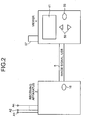
- FIG. 2 is a schematic view of a receiving apparatus and a viewer, which is a compact display device, shown in FIG. 1;
- FIG. 3 is a block diagram showing a configuration of the receiving apparatus;
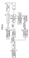
- FIG. 4 is a block diagram showing a configuration of a viewer, which is a compact display device, according to a first embodiment;
- FIG. 5 is a schematic view of showing a configuration of a connecting unit that includes an example of a communication-cable connection detector;
- FIG. 6 is a schematic diagram for explaining switching of a display device of a viewer as a compact display device; and
- FIG. 7 is a block diagram showing a configuration of a viewer, which is a compact display device like that shown in FIG. 1, according to a second embodiment.
-
- 1
- Subject
- 2
- Receiving apparatus
- 2a
- Receiving jacket
- 2b
- External device
- 3
- Capsule endoscope
- 4
- Viewer
- 5
- Communication cable
- 11.
- Tuner
- 12
- Binarizing circuit
- 13
- Superimposing unit
- 14
- Interface unit
- 15
- Sample-and-hold circuit
- 16
- A/D converter
- 17
- Power supply unit
- 18, 56
- Power switch
- 21
- Connector
- 22
- Projection
- 41
- Display unit
- 42
- S/P converter
- 43, 59
- Image processing circuit
- 44
- Changeover switch
- 45
- Position-
information detecting circuit 45 - 46
- Capsule position analyzer
- 47
- Image generating unit
- 48
- Communication-cable connection detector
- 49
- Control unit
- 50
- Operating unit
- 51,
- CON Connecting unit
- 52
- Contact pin
- 53
- Spring
- 54, 55
- Electric path
- 57, A1 to An
- Receiving antenna
- 58
- Receiving circuit
- CON1
- to CONn Connector
- Exemplary embodiments of an intra-subject information acquiring system according to the present invention will be explained below in detail with reference to FIGS. 1 to 7. Note that the present invention is not limited to the embodiments, and various modifications of the embodiments can be made without departing from the scope of the present invention.
- FIG. 1 is a schematic diagram showing an overall configuration of an intra-subject information acquiring system according to the present invention. In FIG. 1, a radio intra-subject information acquiring system includes a receiving
apparatus 2 having a radio receiving function, and a capsule endoscope (a body-insertable apparatus) 3 that is inserted into asubject 1, picks up images within the body cavity, and transmits data such as an image signal to the receivingapparatus 2. The radio intra-subject information acquiring system also includes aviewer 4 as a compact display device that displays a body-cavity image based on an image signal received by the receivingapparatus 2, and acommunication cable 5 as a communication unit that delivers data between the receivingapparatus 2 and theviewer 4 as a compact display device. The receivingapparatus 2 includes a receivingjacket 2a that the subject 1 wears, and anexternal device 2b that performs processing of a received radio signal. - A configuration of the receiving apparatus is explained next with reference to a schematic diagram shown in FIG. 2 and a block diagram shown in FIG. 3. The receiving
apparatus 2 has a function of receiving body-cavity image data radio-transmitted from thecapsule endoscope 3. As shown in FIGS. 2 and 3, the receivingapparatus 2 has a shape wearable by thesubject 1, and includes the receivingjacket 2a having receiving antennas A1 to An, and theexternal device 2b that processes a radio signal received via the receivingjacket 2a. Each of the receiving antennas A1 to An can be directly adhered to the external surface of the subject (human body) 1 in such a manner that the receiving antennas A1 to An are not attached to the receivingjacket 2a, or can be made detachable from the receivingjacket 2a. - The
external device 2b transmits a received image signal to theviewer 4 as a compact display device via the connectedcommunication cable 5. A connector CON is provided on an upper surface of an external surface for the connection to the receiving antennas A1 to An. The receiving antennas A1 to An have connectors CON1 to CONn that connect the receiving antennas to the connector CON. Theexternal device 2b has a function of binarizing a radio signal transmitted from thecapsule endoscope 3 and outputting the resulting signal. In other words, as shown in FIG. 3, theexternal device 2b includes a changeover switch SW that switches a connection of each of the receiving antennas A1 to An, and atuner 11 that is connected to a latter stage of the changeover switch SW, amplifies a radio signal from the receiving antennas A1 to An of which connection is switched by the changeover switch SW, and demodulates the amplified radio signal. Each of abinarizing circuit 12 and a sample-and-hold circuit 15 are connected to the latter stage of thetuner 11. An A/D converter 16 is connected to a latter stage of the sample-and-hold circuit 15. - The superimposing
unit 13 has a function of superimposing information from a switching controller SC onto an image signal binarized by thebinarizing circuit 12, as a superimposer, and outputting the result to ainterface unit 14 connected thereto. The switching controller SC has a strength-receiving-antenna number N1, and an image-receiving-antenna number N2, instructs a switching of the changeover switch SW, and instructs a processing timing of the sample-and-hold circuit 15 and the A/D converter 16. Theinterface unit 14 is connected to thecommunication cable 5 via a connector (not shown). The superimposingunit 13 has an internal memory (not shown), and registers identification information that identifies a subject such as an examination ID input from the outside, into the internal memory. The superimposingunit 13 superimposes information from the switching controller SC onto the image signal, and outputs the superimposed image signal to theinterface unit 14. Apower supply unit 17 includes a battery embedded in theexternal device 2b. When apower switch 18 shown in FIG. 3 is turned on, thepower supply unit 17 supplies power to each of the above internal devices. - The changeover switch SW of the
external device 2b outputs radio signals from the receiving antennas A1 to An to thetuner 11, based on a switch instruction from the switching controller SC. The changeover switch SW has the connector CON as an antenna switch unit that connects each of the receiving antennas A1l to An corresponding to each disposition position of the receiving antennas A1 to An. - In FIG. 3, as described above, the
tuner 11 amplifies a radio signal, outputs a demodulated image signal S1 to thebinarizing circuit 12, and outputs a received strength signal S2 as received electric-filed strength of the amplified radio signal, to the sample-and-hold circuit 15. The image signal binarized by thebinarizing circuit 12 is output to the superimposingunit 13. The A/D converter 16 converts the received strength signal that is sampled and held by the sample-and-hold circuit 15, into a digital signal, and the switching controller SC takes in the resulting digital signal. - The switching controller SC holds the information of a strength-receiving-antenna number N1 and an image-receiving-antenna number N2. The switching controller SC outputs to the changeover switch SW a signal S5 that instructs the changeover switch SW to selectively connect one of the receiving antennas A1 to An corresponding to the strength-receiving-antenna number N1, during a strength receiving period, and that instructs the changeover switch SW to selectively connect one of the receiving antennas A1 to An corresponding to the image-receiving-antenna number N2, during an image receiving period. At the same time, the switching controller SC outputs a signal S3a that instructs a sample-and-hold timing of the sample-and-
hold circuit 15, and a signal S3b that instructs an A/D conversion timing of the A/D converter 16. The switching controller SC also outputs information of one of the receiving antennas A1 to An corresponding to the strength-receiving-antenna number N1 that is taken in during the strength reception period, and information of received strength of each of the receiving antennas A1 to An, to the superimposingunit 13. - The superimposing
unit 13 superimposes the information of the receiving antennas A1 to An corresponding to the strength-receiving-antenna number N1 and the information of the received strength of each of the receiving antennas A1 to An onto the image signal from thebinarizing circuit 12, and outputs the superimposed information to theinterface unit 14. Theinterface unit 14 transmits the image signal to theviewer 4 as a compact display device via thecommunication cable 5. The superimposingunit 13 according to the present invention can also superimpose the information from the switching controller SC and the identification information registered in the internal memory onto the image signal, and output the superimposed information to theinterface unit 14. - The
viewer 4 as a compact display device displays and analyzes the information taken in from the receivingapparatus 2 via thecommunication cable 5. In other words, as shown in FIG. 2, theviewer 4 as a compact display device has a liquid crystal display such as anLCD 41 as a display unit, on the external surface. As shown in FIG. 4, theviewer 4 as a compact display device includes a serial/parallel converter 42 that takes in a signal transmitted from the receivingapparatus 2, and performs serial/parallel conversion on the signal. An image signal output from the serial/parallel converter 42 is output to animage processing circuit 43. The image data processed by theimage processing circuit 43 is output to theLCD 41 via achangeover switch 44, and displayed by theLCD 41. Apower switch 56 is provided on the external surface of theviewer 4 as a compact display device. The communication cable includes a composite cable having a cable that is used to transmit an image signal, and a cable for USB and 232C, and can transmit various kinds of data. - The information of the receiving antennas A1 to An corresponding to the strength-receiving-antenna number N1 and the information of received strength output from the serial/
parallel converter 42 are supplied to the position-information detecting circuit 45. The position-information detecting circuit 45 selects a receiving antenna that receives largest received electric-field strength as a receiving antenna, based on the information of the taken-in received strength, and sequentially outputs a number of the selected receiving antenna as position information, to acapsule position analyzer 46. - The
capsule position analyzer 46 analyzes the position of thecapsule endoscope 3 within the body cavity of the subject, and outputs information on the result of analysis to a position-information-image generating unit 47. The position-information-image generating unit 47 generates and supplies an intra-subject map via thechangeover switch 44 to theLCD 41, which displays the intra-subject map together with the position of thecapsule endoscope 3 as analyzed by thecapsule position analyzer 46. - The
viewer 4 as a compact display device includes a communication-cable connection detector 48, which detects a connection of thecommunication cable 5 to the receivingapparatus 2. As shown in FIG. 5, in the communication-cable connection detector 48, a connectingunit 51 of thecommunication cable 5 includes acontact pin 52 that is electrically connected to a constant voltage source VDD, and aspring 53 that biases thecontact pin 52 to push out thecontact pin 52 to the outside. Aprojection 22 is provided in aconnector 21 of the receiving apparatus at a predetermined position opposing to thecontact pin 52 of the connectingunit 51. When theconnector 21 is fitted to the connectingunit 51, theprojection 22 is brought into contact with thecontact pin 52, thereby pressing thecontact pin 52 to the inside of the connectingunit 51. Because of the pressing, thecontact pin 52 is brought into contact with both anelectric path 54 at the constant voltage source VDD side, and anelectric path 55 at the side of acontrol unit 49, and a detection signal is output to thecontrol unit 49. When theconnector 21 is removed from the connectingunit 51, theprojection 22 is separated from thecontact pin 52, and thecontact pin 52 returns to the original position due to the biasing force of thespring 53. Therefore, thecontact pin 52 is brought into a non-contact state with theelectric path 55 at thecontrol unit 49 side, and the output of a detection signal to thecontrol unit 49 ceases. - The
control unit 49 has a function as a switching unit that switches the display of theLCD 41. In other words, when a detection signal is input from the communication-cable connection detector 48, thecontrol unit 49 switch controls thechangeover switch 44, and switches the display of theLCD 41 to the display of information taken in via thecommunication cable 5. An operatingunit 50 configured by a display changeover switch and the like of thedisplay unit 41 shown in FIG. 2 is connected to thecontrol unit 49. Thecontrol unit 49 switch controls thechangeover switch 44, based on a display switch instruction of the operatingunit 50, selects the information taken in via thecommunication cable 5, and displays the selected information on theLCD 41. - In other words, when the
communication cable 5 is connected to the receivingapparatus 2, and when a detection signal is input from the communication-cable connection detector 48, thecontrol unit 49 switch controls thechangeover switch 44, thereby connecting theimage processing circuit 43 with theLCD 41 and displaying the image data on theLCD 44. When a display switch instruction is input from the display changeover switch of the operatingunit 50, thecontrol unit 49 switch controls thechangeover switch 44, based on the instruction, thereby connecting the position-information-image generating unit 47 with theLCD 41, and displaying the intra-subject map generated by theimage generating unit 47 and the position of thecapsule endoscope 3 on the intra-subject map, on theLCD 44. - The information displayed on the
LCD 41 is not limited to the image data and the position information of the capsule endoscope, and can also include identification information of the subject such as the patient ID mentioned above, a patient name, and age of a patient, information concerning an examination such as a time of examination and an examination ID, information concerning the capsule endoscope such as a capsule ID and remaining battery charge of the capsule, and information concerning the receiving apparatus such as a receiving apparatus ID, a remaining battery charge of thepower supply unit 17, a radio signal receiving state, and an alarm issued by the receiving apparatus. These pieces of information can be superimposed on the image signal, and can be transmitted from the receivingapparatus 2 to theviewer 4 as a compact display device. Alternatively, these pieces of information can be registered in an internal memory (not shown) inside theviewer 4 as a compact display device, for example, within an internal memory in thecontrol unit 49, and corresponding information can be made displayed at least on oneLCD 41, based on a display switch instruction of the operatingunit 50 that can specify a piece of information. For example, as shown in FIG. 6, when the screen of theLCD 41 is A, image data can be displayed. When the screen of theLCD 41 is B, information concerning an examination such as an examination ID and a time of examination can be displayed based on a display switch instruction issued by the operatingunit 50. When the screen of theLCD 41 is C based on the next display switch instruction of the operatingunit 50, the intra-subject map and the position of thecapsule endoscope 3 can be displayed. - As described above, in the present embodiment, the
viewer 4 as a compact display device displays a body-cavity image picked up by thecapsule endoscope 3. Based on a result of detection by the communication-cable connection detector 48, thecontrol unit 49 controls thechangeover switch 44, thereby switching the display of theLCD 41. Information necessary for the examination such as the intra-subject information can be taken in from the receivingapparatus 2 via thecommunication cable 5, and can be displayed on theLCD 41. Therefore, a display unit is not necessary in the receiving apparatus, and a circuit configuration becomes simple. As a result, the receiving apparatus can be made compact and light, and power consumption can be decreased. - In the present embodiment, based on detection of a connection to the receiving
apparatus 2, intra-subject information can be displayed on theLCD 41 according to a switch control within theviewer 4 as a compact display device. Therefore, based on a simple operation of connecting theviewer 4 as a compact display device to the receivingapparatus 2, information necessary for the examination such as image data acquired from thecapsule endoscope 3 can be promptly displayed in real time in theLCD 41 of theviewer 4 as a compact display device. Second embodiment - FIG. 7 is a block diagram showing a configuration of a viewer as a compact display device shown in FIG. 1 according to a second embodiment. Constituent elements similar to those shown in FIG. 4 are denoted with like reference letters or numerals, for the sake of convenience of explanation.
- In the present embodiment, the
viewer 4 as a compact display device can switch between a radio function that theviewer 4 originally has and a receiving function using a wire explained in the first embodiment. In other words, in the present embodiment, theviewer 4 includes a receivingcircuit 58 that receives a radio signal from the receivingantenna 57, and animage processing circuit 59 that image-processes an image signal demodulated by the receivingcircuit 58 and outputs the image-processed image data to thechangeover switch 44, in addition to the configuration shown in FIG. 4. - When the
viewer 4 as a compact display device is in a state before being connected to the receivingapparatus 2 by thecommunication cable 5, the receivingcircuit 58 directly receives an image signal from thecapsule endoscope 3. Thecontrol unit 49 displays the image data demodulated by the receivingcircuit 58 and processed by theimage processing circuit 59, on theLCD 41, based on a switch control of thechangeover switch 44. - When the
communication cable 5 is connected to the receivingapparatus 2 and when the communication-cable connection detector 48 detects the connection, thecontrol unit 49 switch controls thechangeover switch 44 to the radio receiving function (at theimage processing circuit 43 side), thereby displaying the image data from the receivingapparatus 2 on theLCD 41. In this case, the image data received by the receivingcircuit 58 can be stored in an internal memory (not shown), and thereafter, thecontrol unit 49 can control thechangeover switch 44 to display the image data on theLCD 41, based on a switch instruction of the operatingunit 50. Alternatively, the image data can be abandoned without being displayed in theLCD 41. The operatingunit 50 can instruct a display of image data by radio, a display of image data by wire, and a display of position information. - As explained above, in the present embodiment, the
control unit 49 switch controls thechangeover switch 44 to switch between the display of the image data taken in by wire and the display of image data taken in by radio, based on a connection detection by the communication-cable connection detector 48. Information necessary for the examination such as the intra-subject information can be taken in from the receivingapparatus 2 via thecommunication cable 5, and displayed in theLCD 41. Therefore, as in the first embodiment, a display unit is not necessary in the receiving apparatus, and the circuit configuration becomes simple. With this arrangement, the receiving apparatus can be made compact and light, and power consumption can be decreased. - Further, in the present embodiment, as in the first embodiment, by detecting a connection between the
viewer 4 as a compact display device and the receivingapparatus 2, the radio function that theviewer 4 as a compact display device originally has and the receiving function by wire are switch controlled so that information necessary for the examination can be taken in from the receivingapparatus 2 and displayed in theLCD 41. Therefore, information that is necessary for the examination such as the image data acquired from the capsule endoscope can be promptly displayed in real time on theLCD 41 of theviewer 4 as a compact display device. - As described above, the intra-subject information acquiring system according to the present invention is useful for a medical observation apparatus that is inserted into the inside of a human body and observes a examined part of a subject. Particularly, the intra-subject information acquiring system according to the present invention is useful for decreasing the size and weight of a receiving apparatus and decreasing power consumption.
Claims (5)
- An intra-subject information acquiring system including a receiving apparatus that receives intra-subject information radio transmitted from a body-insertable apparatus, and a compact display device that takes in and displays the intra-subject information on a display unit, the intra-subject information acquiring system comprising
a communication unit that connects the receiving apparatus and the compact display device in a communicable manner, wherein
the receiving apparatus outputs at least the intra-subject information to the compact display device via the communication unit, and
the compact display device includes
a detector that detects a connection between the compact display device and the receiving apparatus by the communication unit, and
a switching controller that switches a display of the display unit to a display of the intra-subject information taken in via the communication unit, based on a result of detection by the detector. - An intra-subject information acquiring system including a receiving apparatus that receives intra-subject information radio transmitted from a body-insertable apparatus, and a compact display device that takes in and displays the intra-subject information on a display unit, the intra-subject information acquiring system comprising
a communication unit that connects the receiving apparatus and the compact display device in a communicable manner, wherein
the receiving apparatus outputs at least the intra-subject information to the compact display device via the communication unit, and
the compact display device includes
a detector that detects a connection between the compact display device and the receiving apparatus by the communication unit,
a radio unit that receives intra-subject information radio transmitted from the body-insertable apparatus, and
a switching controller that switch controls a reception operation performed by the radio unit or the communication unit, based on a result of detection by the detector. - The intra-subject information acquiring system according to claim 1 or 2, wherein
the receiving apparatus further includes
a receiving antenna that receives intra-subject information from the body-insertable apparatus,
a received strength detector that detects received strength in the receiving antenna, and
a superimposing unit that superimposes information of received strength detected by the received strength detector, onto the intra-subject information, and
the compact display apparatus further includes
an analyzer that analyzes a position of the body-insertable apparatus, based on information of the received strength, and
an instructing unit that instructs information displayed on the display unit, and
the switching controller switches information displayed on the display unit, according to an instruction of the instructing unit. - The intra-subject information acquiring system according to claim 1 or 2, wherein
the intra-subject information that the body-insertable apparatus transmits includes at least an image signal acquired by imaging a body cavity of the subject, and position information of the body-insertable apparatus,
the compact display device further includes
an instructing unit that instructs information to be displayed on the display unit, and
the switching controller switches information displayed on the display unit, according to an instruction of the instructing unit. - The intra-subject information acquiring system according to claim 3 or 4, wherein
the information displayed on the display unit includes the image signal, information concerning the body-insertable apparatus, information concerning the receiving apparatus, the position information, and information concerning an examination of the subject, and
the display unit displays at least one piece of information among these pieces of information, according to a display switching by the switching controller.
Applications Claiming Priority (2)
| Application Number | Priority Date | Filing Date | Title |
|---|---|---|---|
| JP2005111131A JP4015666B2 (en) | 2005-04-07 | 2005-04-07 | In-subject information acquisition system |
| PCT/JP2006/307339 WO2006109676A1 (en) | 2005-04-07 | 2006-04-06 | System for acquiring information on inside of subject |
Publications (2)
| Publication Number | Publication Date |
|---|---|
| EP1867280A1 true EP1867280A1 (en) | 2007-12-19 |
| EP1867280A4 EP1867280A4 (en) | 2010-11-17 |
Family
ID=37086951
Family Applications (1)
| Application Number | Title | Priority Date | Filing Date |
|---|---|---|---|
| EP06731287A Withdrawn EP1867280A4 (en) | 2005-04-07 | 2006-04-06 | SYSTEM FOR ACQUIRING INFORMATION ABOUT THE INTERIOR OF A PATIENT |
Country Status (6)
| Country | Link |
|---|---|
| US (1) | US8348832B2 (en) |
| EP (1) | EP1867280A4 (en) |
| JP (1) | JP4015666B2 (en) |
| KR (1) | KR100924614B1 (en) |
| CN (1) | CN101146476B (en) |
| WO (1) | WO2006109676A1 (en) |
Cited By (5)
| Publication number | Priority date | Publication date | Assignee | Title |
|---|---|---|---|---|
| EP2074939A1 (en) | 2007-12-25 | 2009-07-01 | Olympus Medical Systems Corporation | Transmitting/receiving system and medical system |
| EP2158835A4 (en) * | 2007-06-27 | 2012-06-13 | Olympus Medical Systems Corp | IMAGE INFORMATION DISPLAY PROCESSING DEVICE |
| US8406490B2 (en) | 2008-04-30 | 2013-03-26 | Given Imaging Ltd. | System and methods for determination of procedure termination |
| US8610765B2 (en) | 2010-11-24 | 2013-12-17 | Kabushiki Kaisha Toshiba | Imaging apparatus, imaging method, and endoscope apparatus |
| US8696602B2 (en) | 2009-03-31 | 2014-04-15 | Given Imaging, Inc. | Method of determining body exit of an ingested capsule |
Families Citing this family (7)
| Publication number | Priority date | Publication date | Assignee | Title |
|---|---|---|---|---|
| JP4602822B2 (en) * | 2005-04-07 | 2010-12-22 | オリンパスメディカルシステムズ株式会社 | In-subject information acquisition system |
| JP4734068B2 (en) | 2005-09-09 | 2011-07-27 | オリンパスメディカルシステムズ株式会社 | Body cavity image observation device |
| JP2009112644A (en) * | 2007-11-08 | 2009-05-28 | Olympus Medical Systems Corp | Image processing device |
| JP5690447B2 (en) * | 2012-10-15 | 2015-03-25 | オリンパスメディカルシステムズ株式会社 | Information management apparatus and capsule endoscope inspection system |
| JP5961126B2 (en) * | 2013-03-04 | 2016-08-02 | 日本光電工業株式会社 | Biological information monitor system |
| WO2020202531A1 (en) * | 2019-04-04 | 2020-10-08 | オリンパス株式会社 | Receiver system |
| CN116421125B (en) * | 2023-04-14 | 2026-05-08 | 深圳硅基智控科技有限公司 | Receiving device and data transmission system for capsule endoscopes |
Family Cites Families (13)
| Publication number | Priority date | Publication date | Assignee | Title |
|---|---|---|---|---|
| US6043839A (en) * | 1997-10-06 | 2000-03-28 | Adair; Edwin L. | Reduced area imaging devices |
| US6402689B1 (en) * | 1998-09-30 | 2002-06-11 | Sicel Technologies, Inc. | Methods, systems, and associated implantable devices for dynamic monitoring of physiological and biological properties of tumors |
| DE10059662B4 (en) * | 1999-12-03 | 2009-04-02 | Hoya Corp. | Electronic endoscope system |
| IL143260A (en) | 2001-05-20 | 2006-09-05 | Given Imaging Ltd | Array system and method for locating an in vivo signal source |
| JP2003125457A (en) * | 2001-10-16 | 2003-04-25 | Toshiba Corp | Wireless communication terminal device and wireless communication method |
| JP3756797B2 (en) * | 2001-10-16 | 2006-03-15 | オリンパス株式会社 | Capsule type medical equipment |
| JP3974769B2 (en) * | 2001-11-06 | 2007-09-12 | オリンパス株式会社 | Capsule medical device |
| JP2004167163A (en) | 2002-11-22 | 2004-06-17 | Olympus Corp | Capsule type medical care system |
| CN100446717C (en) * | 2003-04-25 | 2008-12-31 | 奥林巴斯株式会社 | Capsule Endoscope and Capsule Endoscope System |
| JP3810381B2 (en) * | 2003-04-25 | 2006-08-16 | オリンパス株式会社 | Image display device, image display method, and image display program |
| WO2004100776A1 (en) * | 2003-05-14 | 2004-11-25 | Olympus Corporation | Capsule medical device |
| JP4526245B2 (en) | 2003-07-04 | 2010-08-18 | オリンパス株式会社 | Video signal processing device |
| JP4938231B2 (en) * | 2004-10-25 | 2012-05-23 | ルネサスエレクトロニクス株式会社 | Flatness measuring instrument |
-
2005
- 2005-04-07 JP JP2005111131A patent/JP4015666B2/en not_active Expired - Fee Related
-
2006
- 2006-04-06 EP EP06731287A patent/EP1867280A4/en not_active Withdrawn
- 2006-04-06 CN CN2006800090228A patent/CN101146476B/en not_active Expired - Fee Related
- 2006-04-06 US US11/658,826 patent/US8348832B2/en not_active Expired - Fee Related
- 2006-04-06 WO PCT/JP2006/307339 patent/WO2006109676A1/en not_active Ceased
- 2006-04-06 KR KR1020077022771A patent/KR100924614B1/en not_active Expired - Fee Related
Cited By (7)
| Publication number | Priority date | Publication date | Assignee | Title |
|---|---|---|---|---|
| EP2158835A4 (en) * | 2007-06-27 | 2012-06-13 | Olympus Medical Systems Corp | IMAGE INFORMATION DISPLAY PROCESSING DEVICE |
| EP2074939A1 (en) | 2007-12-25 | 2009-07-01 | Olympus Medical Systems Corporation | Transmitting/receiving system and medical system |
| US8419627B2 (en) | 2007-12-25 | 2013-04-16 | Olympus Medical Systems Corp. | Transmitting/receiving system and medical system |
| US8406490B2 (en) | 2008-04-30 | 2013-03-26 | Given Imaging Ltd. | System and methods for determination of procedure termination |
| EP2113188B1 (en) * | 2008-04-30 | 2016-03-16 | Given Imaging Ltd. | System and methods for determination of procedure termination |
| US8696602B2 (en) | 2009-03-31 | 2014-04-15 | Given Imaging, Inc. | Method of determining body exit of an ingested capsule |
| US8610765B2 (en) | 2010-11-24 | 2013-12-17 | Kabushiki Kaisha Toshiba | Imaging apparatus, imaging method, and endoscope apparatus |
Also Published As
| Publication number | Publication date |
|---|---|
| EP1867280A4 (en) | 2010-11-17 |
| JP4015666B2 (en) | 2007-11-28 |
| KR100924614B1 (en) | 2009-11-02 |
| US8348832B2 (en) | 2013-01-08 |
| KR20070110904A (en) | 2007-11-20 |
| WO2006109676A1 (en) | 2006-10-19 |
| CN101146476A (en) | 2008-03-19 |
| JP2006288543A (en) | 2006-10-26 |
| US20090076320A1 (en) | 2009-03-19 |
| CN101146476B (en) | 2010-05-19 |
Similar Documents
| Publication | Publication Date | Title |
|---|---|---|
| US8269823B2 (en) | In vivo imaging device, display device, imaging and displaying system and intra-subject indwelling system using the same | |
| EP1932464A1 (en) | Electronic endoscope system | |
| US8348832B2 (en) | Intra-subject information acquiring system | |
| EP2769663A1 (en) | Antenna connection unit, receiver, received signal strength correction device, capsule endoscopic system, correction method and program | |
| EP2011430B1 (en) | Antenna unit and receiving system | |
| US8632457B2 (en) | Receiving apparatus and in-vivo information acquiring system using the same | |
| EP2647329A1 (en) | Reception device and capsule-type endoscope system | |
| JP4847075B2 (en) | Receiver | |
| US8175559B2 (en) | Receiving apparatus | |
| EP1922983A1 (en) | Intra-lumen image viewer | |
| CN101262809B (en) | Receiving device, monitoring device, and in-body information acquisition system using them | |
| JP2007068895A (en) | Inspection method of disconnection | |
| EP1967124A1 (en) | In vivo image display device and receiving system | |
| US8135371B2 (en) | Receiving apparatus and receiving system | |
| JP4602822B2 (en) | In-subject information acquisition system | |
| JP4789762B2 (en) | Capsule endoscope system | |
| JP4009610B2 (en) | Receiver | |
| JPWO2012073761A1 (en) | Transceiver, antenna unit, and in-subject introduction system |
Legal Events
| Date | Code | Title | Description |
|---|---|---|---|
| PUAI | Public reference made under article 153(3) epc to a published international application that has entered the european phase |
Free format text: ORIGINAL CODE: 0009012 |
|
| 17P | Request for examination filed |
Effective date: 20071001 |
|
| AK | Designated contracting states |
Kind code of ref document: A1 Designated state(s): DE FR GB |
|
| RBV | Designated contracting states (corrected) |
Designated state(s): DE FR GB |
|
| DAX | Request for extension of the european patent (deleted) | ||
| A4 | Supplementary search report drawn up and despatched |
Effective date: 20101014 |
|
| 17Q | First examination report despatched |
Effective date: 20111205 |
|
| RAP1 | Party data changed (applicant data changed or rights of an application transferred) |
Owner name: OLYMPUS CORPORATION |
|
| RAP1 | Party data changed (applicant data changed or rights of an application transferred) |
Owner name: OLYMPUS CORPORATION |
|
| RAP1 | Party data changed (applicant data changed or rights of an application transferred) |
Owner name: OLYMPUS CORPORATION |
|
| RAP1 | Party data changed (applicant data changed or rights of an application transferred) |
Owner name: OLYMPUS CORPORATION |
|
| RIN1 | Information on inventor provided before grant (corrected) |
Inventor name: SHIGEMORI, TOSHIAKI |
|
| GRAP | Despatch of communication of intention to grant a patent |
Free format text: ORIGINAL CODE: EPIDOSNIGR1 |
|
| RIC1 | Information provided on ipc code assigned before grant |
Ipc: A61B 1/00 20060101ALI20170328BHEP Ipc: A61B 1/04 20060101AFI20170328BHEP Ipc: A61B 5/07 20060101ALI20170328BHEP |
|
| INTG | Intention to grant announced |
Effective date: 20170504 |
|
| STAA | Information on the status of an ep patent application or granted ep patent |
Free format text: STATUS: THE APPLICATION IS DEEMED TO BE WITHDRAWN |
|
| 18D | Application deemed to be withdrawn |
Effective date: 20170915 |