EP1867228A1 - Reel height control for a flexible cutting platform in an agricultural harvesting machine - Google Patents
Reel height control for a flexible cutting platform in an agricultural harvesting machine Download PDFInfo
- Publication number
- EP1867228A1 EP1867228A1 EP07108751A EP07108751A EP1867228A1 EP 1867228 A1 EP1867228 A1 EP 1867228A1 EP 07108751 A EP07108751 A EP 07108751A EP 07108751 A EP07108751 A EP 07108751A EP 1867228 A1 EP1867228 A1 EP 1867228A1
- Authority
- EP
- European Patent Office
- Prior art keywords
- reel support
- float
- reel
- support arm
- agricultural harvesting
- Prior art date
- Legal status (The legal status is an assumption and is not a legal conclusion. Google has not performed a legal analysis and makes no representation as to the accuracy of the status listed.)
- Granted
Links
Images


Classifications
-
- A—HUMAN NECESSITIES
- A01—AGRICULTURE; FORESTRY; ANIMAL HUSBANDRY; HUNTING; TRAPPING; FISHING
- A01D—HARVESTING; MOWING
- A01D41/00—Combines, i.e. harvesters or mowers combined with threshing devices
- A01D41/12—Details of combines
- A01D41/14—Mowing tables
- A01D41/141—Automatic header control
-
- A—HUMAN NECESSITIES
- A01—AGRICULTURE; FORESTRY; ANIMAL HUSBANDRY; HUNTING; TRAPPING; FISHING
- A01D—HARVESTING; MOWING
- A01D57/00—Delivering mechanisms for harvesters or mowers
- A01D57/01—Devices for leading crops to the mowing apparatus
- A01D57/02—Devices for leading crops to the mowing apparatus using reels
Definitions
- the present invention relates to agricultural harvesting machines, such as combines, and, more particularly to agricultural harvesting machines including a cutting platform with a belt conveyor, according to the pre-amble of claim 1.
- An agricultural harvesting machine such as a combine includes a header and a feeder house which remove the crop material from the field, gather the crop material and transport the crop material to a separator.
- a separator In the case of thinner stemmed crops such as soybeans, wheat, etc. which may be cut with a sickle bar carrying a plurality of knives, the head may also be known as a cutting platform.
- the separator removes the grain crop material from the non-grain crop material.
- the grain is cleaned and deposited in a grain tank.
- an unloading auger which is positioned alongside the combine during harvesting is moved to the unloading position in which the auger extends approximately perpendicular to the longitudinal axis of the combine.
- the combine drives alongside a vehicle into which the grain is to be unloaded, such as a semi-trailer, and the unloading auger is actuated to discharge the grain into the vehicle.
- a cutting platform may generally be of two types.
- One type typically has a sheet metal floor with a dual feed auger near the rear of the cutting platform for feeding the crop material longitudinally to the feeder house.
- a cutting platform of this type with auger feed is more common.
- FIG. 1 Another type of cutting platform, also known as a draper platform, utilizes a flat, wide belt, referred to as a draper or draper belt to convey crop material.
- the arrangement and number of belts vary among platforms.
- One style of draper platform has two side belts that convey crop material longitudinally, to the center of the platform, where a center feed belt moves the crop material laterally into the feeder house.
- Each belt is wrapped around a pair of rollers, one being a drive roller and the other being an idler roller.
- a reel extending across the width of the platform moves the crop material from the cutterbar onto the draper belts.
- An example of this type draper arrangement is disclosed in U.S. Patent No. 6,202,397 , which is assigned to the assignee of the present invention.
- An advantage of a draper platform is that larger amounts of crop material can be transported without plugging, etc. For example, with wide platforms approaching 40 feet or even larger, the amount of crop material transported to the feeder house can be substantial. With an auger feed platform, the crop material may bind between the auger and the back wall of the platform. In contrast, with a draper platform, the crop material is carried on top of the belt with less chance for plugging.
- Draper platforms currently in use have a rigid framework not allowing the framework to flex to any appreciable extent during use.
- the draper platform can be placed in a "float" position such that the cutterbar at the leading edge does not dig into the ground, but the leading edge of the platform itself cannot flex across the width of the platform as a result of uneven ground terrain. This results in some crop material being missed in ground depressions, etc., while also possibly causing a part of the cutterbar to dig into localized ground elevations (e.g., small mounds, etc.). Of course, missed crop material directly translates into missed revenue, and localized gouging of soil can cause additional repair expenses resulting from broken knives, knife guards, etc.
- EP 1 510 123 A describes a platform for a combine, in which the height of the reel is automatically controlled dependent on the load of the reel.
- An agricultural harvesting machine includes a feeder house and a cutting platform attached to the feeder house.
- the cutting platform includes at least one platform section, with each platform section having a frame, a cutterbar assembly at a leading edge of the platform section, and an excessive localized deflection indicator associated with the cutterbar assembly.
- One or more pairs of reel support arms are provided, with each pair associated with a corresponding reel. Each pair of reel support arms is movable toward and away from the cutterbar assembly, dependent upon a state of the excessive localized deflection indicator.
- Combine 10 includes a feeder house 14 which is detachably coupled with cutting platform 12.
- Feeder house 14 receives the crop material from cutting platform 12, both grain and non-grain crop material, and transports the crop material to a separator within combine 10 in known manner (not shown).
- the grain crop material is separated from the non-grain crop material, cleaned and transported to a grain tank.
- the non-grain crop material is transported to a chopper, blower, etc. in known manner and distributed back to the field.
- Cutting platform 12 generally includes a plurality of platform sections 16, 18 and 20, a cutterbar assembly 22 and a reel assembly 24.
- platform section 16 is a center platform section
- platform section 18 is a first wing platform section
- platform section 20 is a second wing platform section.
- cutting platform 12 may be configured with more or less platform sections, depending upon the particular application.
- Each platform section 16, 18 and 20 generally includes a frame 26, a plurality of float arms 28 coupled with a respective frame 26, a cutterbar 30 carried by the outboard ends of respective float arms 28, an endless belt 32, and a plurality of belt guides 34.
- the frame 26 of first wing platform section 18 and second wing platform section 20 are each pivotally coupled with center platform section 16, such that the outboard ends of first wing platform section 18 and second wing platform section 20 can move up and down independent from center platform section 16.
- a lift cylinder 36 coupled between the frame of combine 10 and feeder house 14 lifts the entire cutting platform 12, a first tilt cylinder 38 coupled between the respective frame 26 of first wing platform section 18 and center platform section 16 pivotally moves first wing platform section 18 relative to center platform section 16, and a second tilt cylinder 40 coupled between the respective frame 26 of second wing platform section 20 and center platform section 16 pivotally moves second wing platform section 20 relative to center platform section 16.
- Cutterbar assembly 22 includes two cutterbars 30 carried at the outboard ends of float arms 28 (i.e., at the leading edge of a platform section 16, 18 or 20).
- Each cutterbar 30 includes a plurality of knives 42 carried by a bar (not specifically shown).
- the particular type of knife can vary, such as a double blade knife (as shown) or a single blade knife.
- the bar is formed from a metal which is flexible to an extent allowing a desired degree of flexure across the width of cutting platform 12.
- a majority of each cutterbar 30 is carried by a respective first wing platform section 18 or second wing platform section 20, with a lesser extent at the adjacent inboard ends of each cutterbar 30 being carried by center platform section 16.
- Cutterbars 30 are simultaneously driven by a single knife drive 44, providing reciprocating movement in concurrent opposite directions between cutterbars 30. It is also possible to reciprocally drive cutterbars 30 with multiple knife drives, which can be positioned at the adjacent, inboard ends or the outboard ends of cutterbars 30.
- a plurality of knife guards 46 are positioned in opposition to knives 42 for providing opposing surfaces for cutting the crop material with knives 42.
- a plurality of keepers 48 spaced along cutterbars 30 have a distal end above cutterbars 30 for maintaining cutterbars 30 in place during reciprocating movement.
- Float arms 28 may be pivoted at their connection locations with a respective frame 26.
- a float cylinder 50 coupled between a respective frame 26 and float arm 28 may be used for raising or lowering the outboard end of float arm(s) 28 at the leading edge of cutting platform 12.
- Each float cylinder 50 may also be placed in a "float" position allowing the connected float arm 28 to generally follow the ground contour during operation. More particularly, each float cylinder 50 is fluidly connected with an accumulator 52 carried by a platform section 16, 18 or 20. Accumulator 52 allows fluid to flow to and from attached float cylinders 50 such that no pressure build-up occurs.
- each float cylinder 50 is free to move back and forth longitudinally, thereby allowing float arms 28 to follow the ground contour.
- float cylinders 50 can be actuated to move float arms 28 in an upward or downward direction.
- each float cylinder 50 is a hydraulic cylinder, but could possibly be configured as a gas cylinder for a particular application.
- Each float arm 28 is also associated with a respective roller 54.
- the plurality of rollers 54 for each platform section 16, 18 and 20 carry and are positioned within a loop of a respective endless belt 32.
- At the inboard end of first wing platform section 18 and second wing platform section 20 is a driven roller, and at the outboard end of first wing platform section 18 and second wing platform section 20 is an idler roller.
- the rollers positioned between the inboard drive roller and outboard idler roller at each float arm 28 also function as idler rollers. It will be appreciated that the number of float arms 28, and thus the number of rollers 54, may vary depending upon the overall width of cutting head 12 transverse to the travel direction.
- Reel assembly 24 includes two reels 56, center reel support arm 58 and a pair of outer reel support arms 60.
- Each reel 56 carries a plurality of tines for moving the crop material onto platform sectionals 16, 18 and 20.
- Outer reel support arms 60 are pivotally coupled at one end thereof with an outboard end of a respective first wing platform section 18 or second wing platform section 20.
- Outer reel support arms 60 rotationally carry a respective reel 56 at an opposite end thereof.
- Each outer reel support arm 60 may be selectively moved up and down using a hydraulic cylinder, and the pair of hydraulic cylinders are typically coupled in parallel so that they move together upon actuation.
- Center reel support arm 58 is pivotally coupled at one end thereof with center platform section 16 above the opening leading to feeder house 14.
- Center reel support arm 58 rotationally carries an inboard end of each reel 56 at an opposite end thereof.
- a hydraulic motor 62 or other suitable mechanical drive rotationally drives each reel 56. More particularly, hydraulic motor 62 drives a common drive shaft 64 through a chain and sprocket or other suitable arrangement (not shown). The rotational speed of reels 56 can be adjusted by an operator by adjusting the rotational speed of hydraulic motor 62.
- Center reel support arm 58 may be selectively moved up and down using a hydraulic cylinder 66. Center reel support arm 58 is movable independently from outer reel support arms 60. To accommodate this independent movement, drive shaft 64 driven by hydraulic motor 62 is coupled at each end thereof via a universal joint 68 with a respective reel 56. This independent movement of center reel support arm 58 can be accomplished manually using a separate actuating switch or lever in operator's cab 70, or automatically using an electronic controller 72 located within cab 70 or other suitable location.
- Each platform section 16, 18 and 20 has a leading edge which is configured to allow cutterbar assembly 22 to flex an appreciable extent in a localized manner across the width of cutting platform 12.
- each float arm 28 has a distal end adjacent the leading edge of cutting platform 12.
- the float arms 28 associated with each respective platform section 16, 18 and 20 each have a distal end which is fastened to a knife guard 46, flexible substrate 74, crop ramp 76 and hold down 48.
- Flexible substrate 74 for each particular platform section 16, 18 and 20 in essence forms the backbone to which the other modular components are mounted and allows flexibility of the platform section across the width thereof.
- a bushing housing 76 also mounted to flexible substrate 74 carries a bushing (not shown) which rotatably supports roller 54.
- flexible substrate 74 is a steel plate with various mounting holes formed therein, and has a modulus of elasticity providing a desired degree of flexibility.
- the geometric configuration and material type from which flexible substrate 74 is formed may vary, depending upon the application.
- each float arm 28 is provided with a passive stop allowing the float arm to move to a normal stop position during normal operation, and past the normal stop position to an overload stop position during an overload stop condition.
- a condition may occur, for example, when cutterbar assembly 22 is biased upward in a localized manner from a ground protrusion or obstruction, such as a rock, log, mound of dirt, etc. (see Fig. 6). Absent the use of a passive stop, each float arm 28 can reach a hard stop at the upper-most travel position, after which further biasing by the ground protrusion may place the weight of the entire cutting platform 12 and/or feeder house 14 on a single float arm 28.
- float arms 28 must be designed to accommodate such weight, which of course adds to the bulk, weight and cost of cutting platform 12.
- allowing one or more float arms 28 to pivot upwards past the normal stop position during extreme conditions prevents undue stress on the float arm, which in turn allows the size of each float arm 28 to be smaller.
- each float cylinder 50 associated with a respective float arm 28 is identically configured as a dual bore cylinder, with a first bore 78 and a larger diameter second bore 80.
- a floating piston 82 is free floating within second bore 80, and has an inner bore 84 with an inside diameter which is just slightly larger than an outside diameter of rod 86.
- Floating piston 82 is slidably movable back and forth within second bore 80 adjacent a distal end 88 of float cylinder 28 from which rod 86 extends.
- Floating piston 82 is movable to a normal stop position shown in Fig. 5 adjacent first bore 78, and an overload stop position adjacent distal end 88.
- variable volume area within first bore 78 between floating piston 82 and proximal end 90 defines a fluid chamber 92 which can either be placed in a "float” state or which receives high pressure fluid from accumulator chamber 52A for extending rod 86 to lift a corresponding float arm 28.
- the variable volume area within second bore 80 between floating piston 82 and distal end 88 defines a fluid chamber 94 which is in fluid communication with accumulator chamber 52B via fluid line 96.
- the pressure within accumulator chamber 52B and fluid chamber 94 is set to provide a normal stop position for rod 86.
- rod 86 includes a first retainer 98 and a second retainer 100 which are positioned on opposite sides of and engage floating piston 82.
- each of first retainer 98 and second retainer 100 are configured as snap rings, but may be differently configured depending upon the application.
- first retainer 98 engages against the bottom of floating piston 82 which limits the stroke length of rod 86 from distal end 88.
- the pressure exerted by first retainer 98 against floating piston 82 exceeds the predetermined pressure within second bore 80, thus allowing movement of floating piston 82 and further movement of rod 86. Movement of floating piston 82 away from the normal stop position provides an excessive localized deflection indicator of cutterbar assembly 22.
- the fluid which is expelled from fluid chamber 94 is discharged to accumulator chamber 52B under substantially constant pressure.
- the maximum overload stop position occurs at a point in which floating piston 82 second retainer 100 is immediately adjacent distal end 88.
- accumulator 52 is shown as including two concentrically arranged accumulator chambers 52A and 52B operating at different pressures for compactness sake. However, separate accumulators each having a single accumulator chamber may also be provided.
- a localized extreme upward deflection of cutterbar assembly 22 is indicated when rod 86 moves past the normal stop position. This can be detected, for example, by sensing the pressure of the fluid within fluid chamber 94 above a predetermined pressure using a sensor 102 and providing an output signal to controller 72. Other methods of indicating extreme upward deflection of cutterbar assembly 22 can also be used. For example, a single pressure sensor can be used to sense an increase in the pressure within accumulator chamber 52B. This is a simpler method of determining an overload condition in a float cylinder 50, but does not provide an indication of which float cylinder 50 was in an overload state.
- rod 86 can be sensed to determine if the stroke length has exceeded the normal stroke length at the normal stop position.
- Rod 86 could be encoded such as with magnetic or optical encoding to determine when rod 86 has passed the normal stop position. Further, it is possible to sense the angular position of each float arm 28 relative to frame 26 to determine when a float arm 28 has passed the normal stop position.
- reel 56 above a float arm 28 which is determined to have moved past the normal stop position is automatically raised to avoid tines coming into contact with cutterbar assembly 22, which could result in damage to knives 42 and/or tines.
- Reel 56 can be raised by raising center reel support arm 58 and/or outer reel support arm 60.
- the longitudinal position of the particular float arm 28 relative to the support arms 58 and 60 can be used to determine the extent to which support arm(s) 58 and/or 60 must be raised to avoid interference between tines and cutterbar assembly 22.
- reel 56 can be moved to the extent necessary to ensure clearance when floating piston 82 second retainer 100 is at the maximum overload stop position immediately adjacent distal end 88.
- reel 56 is only moved an extent necessary to ensure clearance with cutterbar assembly 22 (i.e., there need not be an extra safety margin in this instance).
- Onboard controller 72 receives one or more sensor signals indicating that a float arm 28 has traveled past the normal stop position, (optionally) a relative location of the float arm 28, and (optionally) the extent of travel past the normal stop position, and actuates reel support arm 58 and/or 60 accordingly. As a simpler approach, it is also possible to raise both reels 56 a predetermined distance upon determining that one or more float arms 28 are in an overload condition.
- cutting platform 12 is placed in a "float" position as combine 10 traverses across the ground.
- a field is opened by making several rounds around the periphery of the field.
- Combine 10 is then moved back and forth across the field, with the combine being shifted approximately the width of cutting platform 12 for each pass across the field.
- the cutting platform 12 is raised while the combine is being turned around for the next pass.
- the outboard ends of float arms 28 float up and down between the top and bottom normal stop positions as cutting platform 12 moves across the field.
- controller 72 determines that a float arm 28 has traveled past a normal stop position and actuates a reel support arm 58 and/or 60 to provide a clearance distance between tines and cutterbar assembly 22.
Abstract
Description
- The present invention relates to agricultural harvesting machines, such as combines, and, more particularly to agricultural harvesting machines including a cutting platform with a belt conveyor, according to the pre-amble of claim 1.
- An agricultural harvesting machine such as a combine includes a header and a feeder house which remove the crop material from the field, gather the crop material and transport the crop material to a separator. In the case of thinner stemmed crops such as soybeans, wheat, etc. which may be cut with a sickle bar carrying a plurality of knives, the head may also be known as a cutting platform. The separator removes the grain crop material from the non-grain crop material. The grain is cleaned and deposited in a grain tank. When the grain tank becomes full, an unloading auger which is positioned alongside the combine during harvesting is moved to the unloading position in which the auger extends approximately perpendicular to the longitudinal axis of the combine. The combine drives alongside a vehicle into which the grain is to be unloaded, such as a semi-trailer, and the unloading auger is actuated to discharge the grain into the vehicle.
- A cutting platform may generally be of two types. One type typically has a sheet metal floor with a dual feed auger near the rear of the cutting platform for feeding the crop material longitudinally to the feeder house. A cutting platform of this type with auger feed is more common.
- Another type of cutting platform, also known as a draper platform, utilizes a flat, wide belt, referred to as a draper or draper belt to convey crop material. The arrangement and number of belts vary among platforms. One style of draper platform has two side belts that convey crop material longitudinally, to the center of the platform, where a center feed belt moves the crop material laterally into the feeder house. Each belt is wrapped around a pair of rollers, one being a drive roller and the other being an idler roller. A reel extending across the width of the platform moves the crop material from the cutterbar onto the draper belts. An example of this type draper arrangement is disclosed in
U.S. Patent No. 6,202,397 , which is assigned to the assignee of the present invention. - An advantage of a draper platform is that larger amounts of crop material can be transported without plugging, etc. For example, with wide platforms approaching 40 feet or even larger, the amount of crop material transported to the feeder house can be substantial. With an auger feed platform, the crop material may bind between the auger and the back wall of the platform. In contrast, with a draper platform, the crop material is carried on top of the belt with less chance for plugging.
- Draper platforms currently in use have a rigid framework not allowing the framework to flex to any appreciable extent during use. The draper platform can be placed in a "float" position such that the cutterbar at the leading edge does not dig into the ground, but the leading edge of the platform itself cannot flex across the width of the platform as a result of uneven ground terrain. This results in some crop material being missed in ground depressions, etc., while also possibly causing a part of the cutterbar to dig into localized ground elevations (e.g., small mounds, etc.). Of course, missed crop material directly translates into missed revenue, and localized gouging of soil can cause additional repair expenses resulting from broken knives, knife guards, etc.
-
EP 1 510 123 A describes a platform for a combine, in which the height of the reel is automatically controlled dependent on the load of the reel. - What is needed in the art is a draper platform which is flexible across the width of the platform on a localized basis, without interfering with the operation of the rotating reel above the platform.
- This object is achieved with the subject matter of claim 1. Advantageous embodiments are recited in the dependent claims.
- An agricultural harvesting machine includes a feeder house and a cutting platform attached to the feeder house. The cutting platform includes at least one platform section, with each platform section having a frame, a cutterbar assembly at a leading edge of the platform section, and an excessive localized deflection indicator associated with the cutterbar assembly. One or more pairs of reel support arms are provided, with each pair associated with a corresponding reel. Each pair of reel support arms is movable toward and away from the cutterbar assembly, dependent upon a state of the excessive localized deflection indicator.
- An embodiment of the invention is shown in the drawings, in which:
- Fig. 1 is a fragmentary, top view of an agricultural combine including an embodiment of a draper platform of the present invention;
- Fig. 2 is a fragmentary, perspective view of the agricultural combine of Fig. 1;
- Fig. 3 is a fragmentary, perspective view of the cutting platform shown in Figs. 1 and 2;
- Fig. 4 is a side, sectional view through a wing platform section shown in Figs. 1 and 2;
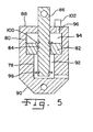
- Fig. 5 is a side sectional view through the float cylinder shown in Figs. 3 and 4; and
- Fig. 6 is a plan view of the cutting platform shown in Figs. 1, 2 and 4, while traversing a localized ground protrusion.
- Referring now to the drawings, and, more particularly to Figs. 1 and 2, there is shown an agricultural harvesting machine in the form of a
combine 10 including an embodiment of acutting platform 12 of the present invention. Combine 10 includes afeeder house 14 which is detachably coupled withcutting platform 12.Feeder house 14 receives the crop material from cuttingplatform 12, both grain and non-grain crop material, and transports the crop material to a separator within combine 10 in known manner (not shown). The grain crop material is separated from the non-grain crop material, cleaned and transported to a grain tank. The non-grain crop material is transported to a chopper, blower, etc. in known manner and distributed back to the field. -
Cutting platform 12 generally includes a plurality ofplatform sections cutterbar assembly 22 and areel assembly 24. In the embodiment shown,platform section 16 is a center platform section,platform section 18 is a first wing platform section, andplatform section 20 is a second wing platform section. Although shown with three platform sections,cutting platform 12 may be configured with more or less platform sections, depending upon the particular application. - Each
platform section frame 26, a plurality offloat arms 28 coupled with arespective frame 26, acutterbar 30 carried by the outboard ends of respectivefloat arms 28, anendless belt 32, and a plurality ofbelt guides 34. Theframe 26 of firstwing platform section 18 and secondwing platform section 20 are each pivotally coupled withcenter platform section 16, such that the outboard ends of firstwing platform section 18 and secondwing platform section 20 can move up and down independent fromcenter platform section 16. To that end, alift cylinder 36 coupled between the frame ofcombine 10 andfeeder house 14 lifts theentire cutting platform 12, afirst tilt cylinder 38 coupled between therespective frame 26 of firstwing platform section 18 andcenter platform section 16 pivotally moves firstwing platform section 18 relative tocenter platform section 16, and asecond tilt cylinder 40 coupled between therespective frame 26 of secondwing platform section 20 andcenter platform section 16 pivotally moves secondwing platform section 20 relative tocenter platform section 16. - Cutterbar
assembly 22 includes twocutterbars 30 carried at the outboard ends of float arms 28 (i.e., at the leading edge of aplatform section cutterbar 30 includes a plurality ofknives 42 carried by a bar (not specifically shown). The particular type of knife can vary, such as a double blade knife (as shown) or a single blade knife. The bar is formed from a metal which is flexible to an extent allowing a desired degree of flexure across the width ofcutting platform 12. In the embodiment shown, a majority of eachcutterbar 30 is carried by a respective firstwing platform section 18 or secondwing platform section 20, with a lesser extent at the adjacent inboard ends of eachcutterbar 30 being carried bycenter platform section 16. Cutterbars 30 are simultaneously driven by asingle knife drive 44, providing reciprocating movement in concurrent opposite directions betweencutterbars 30. It is also possible to reciprocally drivecutterbars 30 with multiple knife drives, which can be positioned at the adjacent, inboard ends or the outboard ends ofcutterbars 30. - A plurality of
knife guards 46 are positioned in opposition toknives 42 for providing opposing surfaces for cutting the crop material withknives 42. A plurality ofkeepers 48 spaced alongcutterbars 30 have a distal end abovecutterbars 30 for maintainingcutterbars 30 in place during reciprocating movement. -
Float arms 28 may be pivoted at their connection locations with arespective frame 26. Afloat cylinder 50 coupled between arespective frame 26 andfloat arm 28 may be used for raising or lowering the outboard end of float arm(s) 28 at the leading edge ofcutting platform 12. Eachfloat cylinder 50 may also be placed in a "float" position allowing the connectedfloat arm 28 to generally follow the ground contour during operation. More particularly, eachfloat cylinder 50 is fluidly connected with anaccumulator 52 carried by aplatform section float cylinders 50 such that no pressure build-up occurs. In this manner, the rams associated with eachfloat cylinder 50 are free to move back and forth longitudinally, thereby allowingfloat arms 28 to follow the ground contour. When not in a float mode,float cylinders 50 can be actuated to movefloat arms 28 in an upward or downward direction. In the embodiment shown, eachfloat cylinder 50 is a hydraulic cylinder, but could possibly be configured as a gas cylinder for a particular application. - Each
float arm 28 is also associated with arespective roller 54. The plurality ofrollers 54 for eachplatform section endless belt 32. At the inboard end of firstwing platform section 18 and secondwing platform section 20 is a driven roller, and at the outboard end of firstwing platform section 18 and secondwing platform section 20 is an idler roller. The rollers positioned between the inboard drive roller and outboard idler roller at eachfloat arm 28 also function as idler rollers. It will be appreciated that the number offloat arms 28, and thus the number ofrollers 54, may vary depending upon the overall width of cuttinghead 12 transverse to the travel direction. -
Reel assembly 24 includes tworeels 56, centerreel support arm 58 and a pair of outerreel support arms 60. Eachreel 56 carries a plurality of tines for moving the crop material ontoplatform sectionals reel support arms 60 are pivotally coupled at one end thereof with an outboard end of a respective firstwing platform section 18 or secondwing platform section 20. Outerreel support arms 60 rotationally carry arespective reel 56 at an opposite end thereof. Each outerreel support arm 60 may be selectively moved up and down using a hydraulic cylinder, and the pair of hydraulic cylinders are typically coupled in parallel so that they move together upon actuation. - Center
reel support arm 58 is pivotally coupled at one end thereof withcenter platform section 16 above the opening leading tofeeder house 14. Centerreel support arm 58 rotationally carries an inboard end of eachreel 56 at an opposite end thereof. Ahydraulic motor 62 or other suitable mechanical drive rotationally drives eachreel 56. More particularly,hydraulic motor 62 drives acommon drive shaft 64 through a chain and sprocket or other suitable arrangement (not shown). The rotational speed ofreels 56 can be adjusted by an operator by adjusting the rotational speed ofhydraulic motor 62. - Center
reel support arm 58 may be selectively moved up and down using ahydraulic cylinder 66. Centerreel support arm 58 is movable independently from outerreel support arms 60. To accommodate this independent movement, driveshaft 64 driven byhydraulic motor 62 is coupled at each end thereof via a universal joint 68 with arespective reel 56. This independent movement of centerreel support arm 58 can be accomplished manually using a separate actuating switch or lever in operator'scab 70, or automatically using anelectronic controller 72 located withincab 70 or other suitable location. - Each
platform section cutterbar assembly 22 to flex an appreciable extent in a localized manner across the width of cuttingplatform 12. Referring to Figs. 3 and 4, eachfloat arm 28 has a distal end adjacent the leading edge of cuttingplatform 12. Thefloat arms 28 associated with eachrespective platform section knife guard 46,flexible substrate 74,crop ramp 76 and hold down 48.Flexible substrate 74 for eachparticular platform section bushing housing 76 also mounted toflexible substrate 74 carries a bushing (not shown) which rotatably supportsroller 54. In the embodiment shown,flexible substrate 74 is a steel plate with various mounting holes formed therein, and has a modulus of elasticity providing a desired degree of flexibility. The geometric configuration and material type from whichflexible substrate 74 is formed may vary, depending upon the application. - In the embodiment shown, each
float arm 28 is provided with a passive stop allowing the float arm to move to a normal stop position during normal operation, and past the normal stop position to an overload stop position during an overload stop condition. Such a condition may occur, for example, whencutterbar assembly 22 is biased upward in a localized manner from a ground protrusion or obstruction, such as a rock, log, mound of dirt, etc. (see Fig. 6). Absent the use of a passive stop, eachfloat arm 28 can reach a hard stop at the upper-most travel position, after which further biasing by the ground protrusion may place the weight of theentire cutting platform 12 and/orfeeder house 14 on asingle float arm 28. This is undesirable since thefloat arms 28 must be designed to accommodate such weight, which of course adds to the bulk, weight and cost of cuttingplatform 12. On the other hand, allowing one ormore float arms 28 to pivot upwards past the normal stop position during extreme conditions prevents undue stress on the float arm, which in turn allows the size of eachfloat arm 28 to be smaller. - More particularly, referring to Figs. 4 and 5, each
float cylinder 50 associated with arespective float arm 28 is identically configured as a dual bore cylinder, with afirst bore 78 and a larger diameter second bore 80. A floatingpiston 82 is free floating withinsecond bore 80, and has aninner bore 84 with an inside diameter which is just slightly larger than an outside diameter ofrod 86. Floatingpiston 82 is slidably movable back and forth withinsecond bore 80 adjacent adistal end 88 offloat cylinder 28 from whichrod 86 extends. Floatingpiston 82 is movable to a normal stop position shown in Fig. 5 adjacentfirst bore 78, and an overload stop position adjacentdistal end 88. - The variable volume area within
first bore 78 between floatingpiston 82 andproximal end 90 defines afluid chamber 92 which can either be placed in a "float" state or which receives high pressure fluid fromaccumulator chamber 52A for extendingrod 86 to lift acorresponding float arm 28. The variable volume area withinsecond bore 80 between floatingpiston 82 anddistal end 88 defines afluid chamber 94 which is in fluid communication withaccumulator chamber 52B viafluid line 96. The pressure withinaccumulator chamber 52B andfluid chamber 94 is set to provide a normal stop position forrod 86. To that end,rod 86 includes afirst retainer 98 and asecond retainer 100 which are positioned on opposite sides of and engage floatingpiston 82. In the embodiment shown, each offirst retainer 98 andsecond retainer 100 are configured as snap rings, but may be differently configured depending upon the application. Under normal operating conditions,first retainer 98 engages against the bottom of floatingpiston 82 which limits the stroke length ofrod 86 fromdistal end 88. However, in the event of a localized extreme upward deflection ofcutterbar assembly 22, and in turn the outboard end offloat arm 28, the pressure exerted byfirst retainer 98 against floatingpiston 82 exceeds the predetermined pressure withinsecond bore 80, thus allowing movement of floatingpiston 82 and further movement ofrod 86. Movement of floatingpiston 82 away from the normal stop position provides an excessive localized deflection indicator ofcutterbar assembly 22. The fluid which is expelled fromfluid chamber 94 is discharged toaccumulator chamber 52B under substantially constant pressure. The maximum overload stop position occurs at a point in which floatingpiston 82second retainer 100 is immediately adjacentdistal end 88. - In the embodiment shown,
accumulator 52 is shown as including two concentrically arrangedaccumulator chambers - Further, in the embodiment shown, a localized extreme upward deflection of
cutterbar assembly 22 is indicated whenrod 86 moves past the normal stop position. This can be detected, for example, by sensing the pressure of the fluid withinfluid chamber 94 above a predetermined pressure using asensor 102 and providing an output signal tocontroller 72. Other methods of indicating extreme upward deflection ofcutterbar assembly 22 can also be used. For example, a single pressure sensor can be used to sense an increase in the pressure withinaccumulator chamber 52B. This is a simpler method of determining an overload condition in afloat cylinder 50, but does not provide an indication of which floatcylinder 50 was in an overload state. Alternatively, the position ofrod 86 can be sensed to determine if the stroke length has exceeded the normal stroke length at the normal stop position.Rod 86 could be encoded such as with magnetic or optical encoding to determine whenrod 86 has passed the normal stop position. Further, it is possible to sense the angular position of eachfloat arm 28 relative to frame 26 to determine when afloat arm 28 has passed the normal stop position. - Regardless of the particular method used, reel 56 above a
float arm 28 which is determined to have moved past the normal stop position is automatically raised to avoid tines coming into contact withcutterbar assembly 22, which could result in damage toknives 42 and/or tines.Reel 56 can be raised by raising centerreel support arm 58 and/or outerreel support arm 60. The longitudinal position of theparticular float arm 28 relative to thesupport arms cutterbar assembly 22. In the event the exact position ofrod 86 is not known after traveling past the normal stop position, such as using the hydraulic passive stop offloat cylinders 28 described above, then reel 56 can be moved to the extent necessary to ensure clearance when floatingpiston 82second retainer 100 is at the maximum overload stop position immediately adjacentdistal end 88. On the other hand, when the exact position ofrod 86 is known after traveling past the normal stop position, such as by sensing the stroke length ofrod 86 or angular orientation offloat arm 28, then reel 56 is only moved an extent necessary to ensure clearance with cutterbar assembly 22 (i.e., there need not be an extra safety margin in this instance).Onboard controller 72 receives one or more sensor signals indicating that afloat arm 28 has traveled past the normal stop position, (optionally) a relative location of thefloat arm 28, and (optionally) the extent of travel past the normal stop position, and actuatesreel support arm 58 and/or 60 accordingly. As a simpler approach, it is also possible to raise both reels 56 a predetermined distance upon determining that one ormore float arms 28 are in an overload condition. - During harvesting operation, cutting
platform 12 is placed in a "float" position ascombine 10 traverses across the ground. Typically, a field is opened by making several rounds around the periphery of the field.Combine 10 is then moved back and forth across the field, with the combine being shifted approximately the width of cuttingplatform 12 for each pass across the field. At opposite ends of the field, the cuttingplatform 12 is raised while the combine is being turned around for the next pass. Under normal operating conditions, the outboard ends offloat arms 28 float up and down between the top and bottom normal stop positions as cuttingplatform 12 moves across the field. In theevent cutterbar assembly 22 encounters an abrupt localized ground protrusion (Fig. 6),controller 72 determines that afloat arm 28 has traveled past a normal stop position and actuates areel support arm 58 and/or 60 to provide a clearance distance between tines andcutterbar assembly 22.
Claims (10)
- An agricultural harvesting machine (10), comprising:a feeder house; anda cutting platform (12) attached to said feeder house (14), said cutting platform (12) including:at least one platform section (16, 18, 20), each said platform section (16, 18, 20) having a frame (26), a cutterbar assembly (22) at a leading edge of said platform section (16, 18, 20);at least one reel (56); andat least one pair of reel support arms (58, 60), each said pair of reel support arms (58, 60) associated with a corresponding reel (56), each said pair of reel support arms (56, 60) movable toward and away from said cutterbar assembly (22),characterized in that an excessive localized deflection indicator is associated with said cutterbar assembly (22), and that the pair of reel support arms (56, 60) movable toward and away from said cutterbar assembly (22) dependent upon a state of said excessive localized deflection indicator.
- The agricultural harvesting machine (10) of claim 1, wherein said excessive localized deflection indicator provides an output signal indicating an excessive localized deflection of said cutterbar assembly (22), and including a controller (72) receiving said output signal and actuating at least one said pair of reel support arms (58, 60).
- The agricultural harvesting machine (10) of claim 2, wherein said at least one pair of reel support arms (58, 60) includes a first reel support arm (58) and a second reel support arm (60), said controller (72) moving at least one of said first reel support arm (58) and said second reel support arm (60).
- The agricultural harvesting machine (10) of claim 3, wherein said controller (72) moves each of said first reel support arm (58) and said second reel support arm (60).
- The agricultural harvesting machine (10) of claim 3, wherein said at least one reel comprises two reels (56) and including a third reel support arm (60), said first reel support arm (60) and said second reel support arm (58) comprising one said pair of reel support arms (58, 60), said second reel support arm (58) and said third reel support arm (60) comprising another said pair of reel support arms (58, 60).
- The agricultural harvesting machine (10) of claim 5, wherein each of said first reel support arm (60), said second reel support arm (58) and said third reel support arm (60) are independently movable using said controller (72).
- The agricultural harvesting machine (10) of claim 1, wherein each said platform section (16, 18, 20) includes a plurality of float arms (28) pivotally coupled with said frame (26), and an endless belt (32) carried by said plurality of float arms (28), said excessive localized deflection indicator associated with at least one said float arm (28).
- The agricultural harvesting (10) machine of claim 7, wherein said excessive localized deflection indicator comprises a plurality of indicators, each said indicator associated with a respective said float arm (28).
- The agricultural harvesting machine (10) of claim 8, including a plurality of float cylinders (50), each said float cylinder (50) associated with a respective said float arm (28) and including a passive stop, each of said indicators comprising one of a pressure sensor (102) and a position indicator associated with a respective said float cylinder (50).
- The agricultural harvesting machine (10) of claim 9, wherein each said float cylinder (50) includes a passive stop, each said indicator associated with a respective said passive stop.
Applications Claiming Priority (1)
| Application Number | Priority Date | Filing Date | Title |
|---|---|---|---|
| US11/452,774 US7805921B2 (en) | 2006-06-14 | 2006-06-14 | Reel height control for flexible cutting platform in an agricultural harvesting machine |
Publications (2)
| Publication Number | Publication Date |
|---|---|
| EP1867228A1 true EP1867228A1 (en) | 2007-12-19 |
| EP1867228B1 EP1867228B1 (en) | 2009-12-30 |
Family
ID=38474074
Family Applications (1)
| Application Number | Title | Priority Date | Filing Date |
|---|---|---|---|
| EP07108751A Active EP1867228B1 (en) | 2006-06-14 | 2007-05-23 | Reel height control for a flexible cutting platform in an agricultural harvesting machine |
Country Status (5)
| Country | Link |
|---|---|
| US (1) | US7805921B2 (en) |
| EP (1) | EP1867228B1 (en) |
| AR (1) | AR061363A1 (en) |
| DE (1) | DE602007004024D1 (en) |
| RU (1) | RU2454061C2 (en) |
Cited By (19)
| Publication number | Priority date | Publication date | Assignee | Title |
|---|---|---|---|---|
| EP2111742A1 (en) * | 2008-04-25 | 2009-10-28 | Deere & Company | Sectionalized belt guide for draper belt in an agricultural harvesting machine |
| WO2009136265A1 (en) * | 2008-05-09 | 2009-11-12 | Agco Corporation | Flexible draper and cutter bar having shiftable crop divider with deflector |
| US7802417B2 (en) | 2006-02-10 | 2010-09-28 | Agco Corporation | Combine harvester draper header central auger transition floor pan |
| US7827773B2 (en) | 2008-05-09 | 2010-11-09 | AGCO Cororation | Center crop deflector for draper header |
| US7836671B2 (en) | 2006-02-10 | 2010-11-23 | Agco Corporation | Flexible draper and cutter bar with tilt arm for cutterbar drive |
| US7874132B2 (en) | 2008-05-09 | 2011-01-25 | Agco Corporation | Header height control system with multiple potentiometer input |
| US7877976B2 (en) | 2008-05-09 | 2011-02-01 | Agco Corporation | Spring flotation for center deck of draper header |
| US7886511B2 (en) | 2008-05-09 | 2011-02-15 | Agco Corporation | Draper head with flexible cutterbar having rigid center section |
| US7886512B2 (en) | 2006-02-10 | 2011-02-15 | Agco Corporation | Draper belt interlocking guards |
| US7913481B2 (en) | 2008-05-09 | 2011-03-29 | Agco Corporation | Adjustable cutterbar travel range for a flexible cutterbar header |
| US7921627B2 (en) | 2008-05-09 | 2011-04-12 | Agco Corporation | Interlocking belt guards for a draper header |
| US7958711B1 (en) | 2010-06-16 | 2011-06-14 | Agco Corporation | Crop deflector for ends of draper belt of flexible draper header |
| US8205421B2 (en) | 2010-06-16 | 2012-06-26 | Agco Corporation | Belt guard crop dam for flexible draper header |
| US8555607B2 (en) | 2008-04-25 | 2013-10-15 | Deere & Company | Integrated draper belt support and skid shoe in an agricultural harvesting machine |
| RU2512307C2 (en) * | 2009-03-06 | 2014-04-10 | Дир Энд Компани | Agricultural harvester with unloading by accelerated draper apron |
| WO2019111069A1 (en) * | 2017-12-08 | 2019-06-13 | Agco Corporation | Flexible header with sectional height adjustment |
| WO2019136281A1 (en) * | 2018-01-04 | 2019-07-11 | Cnh Industrial America Llc | Agricultural harvester with header having conformable portions |
| EP3581015A1 (en) * | 2018-06-11 | 2019-12-18 | Deere & Company | Unitary component crop ramp and belt support |
| EP3653040A1 (en) * | 2018-11-14 | 2020-05-20 | CNH Industrial Belgium N.V. | Reel drive assembly for an agricultural header |
Families Citing this family (26)
| Publication number | Priority date | Publication date | Assignee | Title |
|---|---|---|---|---|
| US7866132B2 (en) * | 2009-05-20 | 2011-01-11 | Deere & Company | Harvesting head reel support arrangement including hydraulic cylinders and control circuitry |
| US8635842B2 (en) | 2009-08-05 | 2014-01-28 | Kevin Markt | Flexible row crop header for an agricultural harvester |
| US20120011819A1 (en) * | 2010-07-19 | 2012-01-19 | Agco Corporation | Header With Adjustable Lean Bar |
| US8322520B2 (en) * | 2010-08-17 | 2012-12-04 | Deere & Company | Tongue-in-groove belt hold down for a draper platform |
| DE102010037131A1 (en) * | 2010-08-24 | 2012-03-01 | Claas Selbstfahrende Erntemaschinen Gmbh | cutting |
| US8347594B1 (en) * | 2011-10-25 | 2013-01-08 | Deere & Company | Pivoting mount for a knife drive |
| US8573388B2 (en) * | 2011-10-31 | 2013-11-05 | Deere & Company | Conveyor belt tensioner for an agricultural harvesting header |
| US8479483B1 (en) | 2011-12-27 | 2013-07-09 | Agco Corporation | Flexible draper head providing reduced crop residue accumulation |
| US8752359B2 (en) * | 2012-08-31 | 2014-06-17 | Macdon Industries Ltd. | Draper support of a crop harvesting header |
| DE102012108835A1 (en) | 2012-09-19 | 2014-03-20 | Claas Selbstfahrende Erntemaschinen Gmbh | cutting |
| DE102013100322A1 (en) * | 2013-01-14 | 2014-07-17 | Claas Selbstfahrende Erntemaschinen Gmbh | cutting |
| US9198349B2 (en) * | 2013-07-12 | 2015-12-01 | Deere & Company | Articulated harvesting head ground force control circuit |
| US10201125B2 (en) | 2014-09-05 | 2019-02-12 | Cnh Industrial America Llc | Combined center cam and reel arm |
| BR102015003443B1 (en) * | 2015-02-18 | 2020-10-20 | Onivaldo Favoretto | anti-loss cutting system with floating reel |
| US10624260B2 (en) * | 2016-11-24 | 2020-04-21 | Macdon Industries Ltd. | Multi-section header with flexible crop cutting knife |
| US10462968B2 (en) * | 2016-11-24 | 2019-11-05 | Macdon Industries Ltd. | Header with flexible crop cutting knife |
| US10238033B2 (en) * | 2017-02-27 | 2019-03-26 | Cnh Industrial America Llc | Reel finger assembly for a harvesting reel |
| US10477765B2 (en) * | 2017-09-20 | 2019-11-19 | Cnh Industrial America Llc | Rotatable coupler for a reel arm of a reel header |
| DE102018107804A1 (en) * | 2018-04-03 | 2019-10-10 | Claas Selbstfahrende Erntemaschinen Gmbh | Height control system for a header |
| EP3669636B1 (en) * | 2018-12-20 | 2022-08-10 | CNH Industrial Belgium NV | A split reel combine header |
| US11617304B2 (en) * | 2019-10-25 | 2023-04-04 | Cnh Industrial America Llc | Staggered harvester head reel position adjustment |
| US11758846B2 (en) | 2019-12-23 | 2023-09-19 | Cnh Industrial America Llc | Header control system to adjust a header of a harvester based on sensor information |
| US11337371B2 (en) * | 2019-12-23 | 2022-05-24 | Cnh Industrial America Llc | Systems and methods for limiting reel adjustment in an agricultural header |
| US11382262B2 (en) * | 2020-01-13 | 2022-07-12 | Cnh Industrial America Llc | Infeed head flex to rigid mode lock out mechanism |
| US11559000B2 (en) * | 2020-05-29 | 2023-01-24 | Deere & Company | Lockout system for header |
| IT202000017947A1 (en) | 2020-07-24 | 2022-01-24 | Dominoni S R L | IMPROVED COMBINE HEADER |
Citations (5)
| Publication number | Priority date | Publication date | Assignee | Title |
|---|---|---|---|---|
| GB1096140A (en) * | 1964-08-14 | 1967-12-20 | Texas Industries Inc | Improvements in or relating to a combine harvester |
| US3698164A (en) | 1970-07-09 | 1972-10-17 | Allis Chalmers Mfg Co | Automatic header height control sensed from floating crop engaging mechanism |
| US4204383A (en) | 1978-06-29 | 1980-05-27 | Allis-Chalmers Corporation | Automatic height control for gathering reel for agricultural combine |
| US6202397B1 (en) | 1999-05-27 | 2001-03-20 | Deere & Company | Draper belt tensioning mechanism for a harvesting platform |
| EP1510123A1 (en) | 2003-08-26 | 2005-03-02 | CLAAS Selbstfahrende Erntemaschinen GmbH | Method and device for controlling a height-adjustable cutting device |
Family Cites Families (7)
| Publication number | Priority date | Publication date | Assignee | Title |
|---|---|---|---|---|
| US3982383A (en) * | 1974-11-13 | 1976-09-28 | Deere & Company | Harvesting platform with a floating cutter bar |
| US4124970A (en) * | 1977-06-03 | 1978-11-14 | Sperry Rand Corporation | Automatic reel height control for a harvester header having a flexible cutterbar |
| US4280318A (en) * | 1980-04-02 | 1981-07-28 | Sperry Corporation | Infinite reel adjustment mechanism |
| SU1347891A1 (en) * | 1986-02-20 | 1987-10-30 | П.Л.Шилько, И.В.Глазков и С.М.Невзоропа | Grain combine header |
| EP0250650B1 (en) * | 1986-06-24 | 1990-09-19 | FORD NEW HOLLAND, INC. (a Delaware corp.) | Header for harvesting machine |
| CA2387898C (en) * | 2001-06-18 | 2005-01-11 | Macdon Industries Ltd. | Multi-section header with flexible crop cutting knife |
| US20070193243A1 (en) | 2006-02-10 | 2007-08-23 | Schmidt James R | Combine Harvester Draper Header Having Flexible Cutterbar |
-
2006
- 2006-06-14 US US11/452,774 patent/US7805921B2/en active Active
-
2007
- 2007-05-23 EP EP07108751A patent/EP1867228B1/en active Active
- 2007-05-23 DE DE602007004024T patent/DE602007004024D1/en active Active
- 2007-06-13 RU RU2007121954/13A patent/RU2454061C2/en not_active IP Right Cessation
- 2007-06-13 AR ARP070102588A patent/AR061363A1/en active IP Right Grant
Patent Citations (5)
| Publication number | Priority date | Publication date | Assignee | Title |
|---|---|---|---|---|
| GB1096140A (en) * | 1964-08-14 | 1967-12-20 | Texas Industries Inc | Improvements in or relating to a combine harvester |
| US3698164A (en) | 1970-07-09 | 1972-10-17 | Allis Chalmers Mfg Co | Automatic header height control sensed from floating crop engaging mechanism |
| US4204383A (en) | 1978-06-29 | 1980-05-27 | Allis-Chalmers Corporation | Automatic height control for gathering reel for agricultural combine |
| US6202397B1 (en) | 1999-05-27 | 2001-03-20 | Deere & Company | Draper belt tensioning mechanism for a harvesting platform |
| EP1510123A1 (en) | 2003-08-26 | 2005-03-02 | CLAAS Selbstfahrende Erntemaschinen GmbH | Method and device for controlling a height-adjustable cutting device |
Cited By (29)
| Publication number | Priority date | Publication date | Assignee | Title |
|---|---|---|---|---|
| US7886512B2 (en) | 2006-02-10 | 2011-02-15 | Agco Corporation | Draper belt interlocking guards |
| US7802417B2 (en) | 2006-02-10 | 2010-09-28 | Agco Corporation | Combine harvester draper header central auger transition floor pan |
| US7836671B2 (en) | 2006-02-10 | 2010-11-23 | Agco Corporation | Flexible draper and cutter bar with tilt arm for cutterbar drive |
| US7937920B2 (en) | 2006-02-10 | 2011-05-10 | Agco Corporation | Combine harvester draper header having flexible cutterbar |
| US7926248B2 (en) | 2006-02-10 | 2011-04-19 | Agco Corporation | Combine harvester draper header having flexible cutterbar |
| US8555607B2 (en) | 2008-04-25 | 2013-10-15 | Deere & Company | Integrated draper belt support and skid shoe in an agricultural harvesting machine |
| US8776487B2 (en) | 2008-04-25 | 2014-07-15 | Deere & Company | Integrated draper belt support and skid shoe in an agricultural harvesting machine |
| EP2111742A1 (en) * | 2008-04-25 | 2009-10-28 | Deere & Company | Sectionalized belt guide for draper belt in an agricultural harvesting machine |
| US7827775B2 (en) | 2008-05-09 | 2010-11-09 | Agco Corporation | Flexible draper and cutter bar having shiftable crop divider with deflector |
| US7886511B2 (en) | 2008-05-09 | 2011-02-15 | Agco Corporation | Draper head with flexible cutterbar having rigid center section |
| US7913481B2 (en) | 2008-05-09 | 2011-03-29 | Agco Corporation | Adjustable cutterbar travel range for a flexible cutterbar header |
| US7921627B2 (en) | 2008-05-09 | 2011-04-12 | Agco Corporation | Interlocking belt guards for a draper header |
| US7877976B2 (en) | 2008-05-09 | 2011-02-01 | Agco Corporation | Spring flotation for center deck of draper header |
| US7874132B2 (en) | 2008-05-09 | 2011-01-25 | Agco Corporation | Header height control system with multiple potentiometer input |
| US7827773B2 (en) | 2008-05-09 | 2010-11-09 | AGCO Cororation | Center crop deflector for draper header |
| CN102065675B (en) * | 2008-05-09 | 2012-11-07 | 爱科公司 | Draper head with flexible cutterbar having rigid center section |
| WO2009136265A1 (en) * | 2008-05-09 | 2009-11-12 | Agco Corporation | Flexible draper and cutter bar having shiftable crop divider with deflector |
| CN102065676B (en) * | 2008-05-09 | 2013-11-20 | 爱科公司 | Flexible draper and cutter bar having shiftable crop divider with deflector |
| RU2512307C2 (en) * | 2009-03-06 | 2014-04-10 | Дир Энд Компани | Agricultural harvester with unloading by accelerated draper apron |
| US7958711B1 (en) | 2010-06-16 | 2011-06-14 | Agco Corporation | Crop deflector for ends of draper belt of flexible draper header |
| US8205421B2 (en) | 2010-06-16 | 2012-06-26 | Agco Corporation | Belt guard crop dam for flexible draper header |
| WO2019111069A1 (en) * | 2017-12-08 | 2019-06-13 | Agco Corporation | Flexible header with sectional height adjustment |
| US10959374B2 (en) | 2017-12-08 | 2021-03-30 | Agco Corporation | Flexible header with sectional height adjustment |
| WO2019136281A1 (en) * | 2018-01-04 | 2019-07-11 | Cnh Industrial America Llc | Agricultural harvester with header having conformable portions |
| US11758840B2 (en) | 2018-01-04 | 2023-09-19 | Cnh Industrial America Llc | Agricultural harvester with header having conformable portions |
| EP3581015A1 (en) * | 2018-06-11 | 2019-12-18 | Deere & Company | Unitary component crop ramp and belt support |
| US10813290B2 (en) | 2018-06-11 | 2020-10-27 | Deere & Company | Component and method for crop ramp and belt support |
| EP3653040A1 (en) * | 2018-11-14 | 2020-05-20 | CNH Industrial Belgium N.V. | Reel drive assembly for an agricultural header |
| US11051453B2 (en) | 2018-11-14 | 2021-07-06 | Cnh Industrial America Llc | Reel drive assembly for an agricultural header |
Also Published As
| Publication number | Publication date |
|---|---|
| US20070289278A1 (en) | 2007-12-20 |
| AR061363A1 (en) | 2008-08-20 |
| EP1867228B1 (en) | 2009-12-30 |
| DE602007004024D1 (en) | 2010-02-11 |
| RU2454061C2 (en) | 2012-06-27 |
| US7805921B2 (en) | 2010-10-05 |
| RU2007121954A (en) | 2008-12-20 |
Similar Documents
| Publication | Publication Date | Title |
|---|---|---|
| EP1867228B1 (en) | Reel height control for a flexible cutting platform in an agricultural harvesting machine | |
| US7937919B2 (en) | Flexible cutting platform with passive float arm stop in an agricultural harvesting machine | |
| EP1993342B1 (en) | Height control for a multi-section cutting platform in an agricultural harvesting machine | |
| EP1993345B1 (en) | Lockout for float arms in a cutting platform of an agricultural harvesting machine | |
| EP1993340B1 (en) | Independent center reel position adjustment for an agricultural harvesting machine | |
| EP1993344B1 (en) | Flexible cutting platform to follow ground contour in an agricultural harvesting machine | |
| CA2642782C (en) | Sectionalized belt guide for draper belt in an agricultural harvesting machine | |
| US8438823B2 (en) | Flexible draper belt drive for an agricultural harvesting machine | |
| EP2111742B1 (en) | Sectionalized belt guide for draper belt in an agricultural harvesting machine | |
| EP2145525A2 (en) | Sectionalized belt guide for draper belt in an agricultural harvesting machine |
Legal Events
| Date | Code | Title | Description |
|---|---|---|---|
| PUAI | Public reference made under article 153(3) epc to a published international application that has entered the european phase |
Free format text: ORIGINAL CODE: 0009012 |
|
| AK | Designated contracting states |
Kind code of ref document: A1 Designated state(s): AT BE BG CH CY CZ DE DK EE ES FI FR GB GR HU IE IS IT LI LT LU LV MC MT NL PL PT RO SE SI SK TR |
|
| AX | Request for extension of the european patent |
Extension state: AL BA HR MK YU |
|
| 17P | Request for examination filed |
Effective date: 20080619 |
|
| 17Q | First examination report despatched |
Effective date: 20080728 |
|
| AKX | Designation fees paid |
Designated state(s): BE DE DK IT PL SE |
|
| GRAP | Despatch of communication of intention to grant a patent |
Free format text: ORIGINAL CODE: EPIDOSNIGR1 |
|
| GRAS | Grant fee paid |
Free format text: ORIGINAL CODE: EPIDOSNIGR3 |
|
| GRAA | (expected) grant |
Free format text: ORIGINAL CODE: 0009210 |
|
| AK | Designated contracting states |
Kind code of ref document: B1 Designated state(s): BE DE DK IT PL SE |
|
| REF | Corresponds to: |
Ref document number: 602007004024 Country of ref document: DE Date of ref document: 20100211 Kind code of ref document: P |
|
| PG25 | Lapsed in a contracting state [announced via postgrant information from national office to epo] |
Ref country code: SE Free format text: LAPSE BECAUSE OF FAILURE TO SUBMIT A TRANSLATION OF THE DESCRIPTION OR TO PAY THE FEE WITHIN THE PRESCRIBED TIME-LIMIT Effective date: 20091230 |
|
| PG25 | Lapsed in a contracting state [announced via postgrant information from national office to epo] |
Ref country code: PL Free format text: LAPSE BECAUSE OF FAILURE TO SUBMIT A TRANSLATION OF THE DESCRIPTION OR TO PAY THE FEE WITHIN THE PRESCRIBED TIME-LIMIT Effective date: 20091230 |
|
| PG25 | Lapsed in a contracting state [announced via postgrant information from national office to epo] |
Ref country code: BE Free format text: LAPSE BECAUSE OF FAILURE TO SUBMIT A TRANSLATION OF THE DESCRIPTION OR TO PAY THE FEE WITHIN THE PRESCRIBED TIME-LIMIT Effective date: 20091230 |
|
| PLBE | No opposition filed within time limit |
Free format text: ORIGINAL CODE: 0009261 |
|
| STAA | Information on the status of an ep patent application or granted ep patent |
Free format text: STATUS: NO OPPOSITION FILED WITHIN TIME LIMIT |
|
| 26N | No opposition filed |
Effective date: 20101001 |
|
| PG25 | Lapsed in a contracting state [announced via postgrant information from national office to epo] |
Ref country code: DK Free format text: LAPSE BECAUSE OF FAILURE TO SUBMIT A TRANSLATION OF THE DESCRIPTION OR TO PAY THE FEE WITHIN THE PRESCRIBED TIME-LIMIT Effective date: 20091230 |
|
| PG25 | Lapsed in a contracting state [announced via postgrant information from national office to epo] |
Ref country code: IT Free format text: LAPSE BECAUSE OF NON-PAYMENT OF DUE FEES Effective date: 20100523 |
|
| PGFP | Annual fee paid to national office [announced via postgrant information from national office to epo] |
Ref country code: IT Payment date: 20140523 Year of fee payment: 8 |
|
| PG25 | Lapsed in a contracting state [announced via postgrant information from national office to epo] |
Ref country code: IT Free format text: LAPSE BECAUSE OF NON-PAYMENT OF DUE FEES Effective date: 20150523 |
|
| PGFP | Annual fee paid to national office [announced via postgrant information from national office to epo] |
Ref country code: DE Payment date: 20230419 Year of fee payment: 17 |