EP1866027B1 - Combinaisons cardio-vasculaires à inhibiteurs d'ace et d'hmg coa - Google Patents
Combinaisons cardio-vasculaires à inhibiteurs d'ace et d'hmg coa Download PDFInfo
- Publication number
- EP1866027B1 EP1866027B1 EP06795473.5A EP06795473A EP1866027B1 EP 1866027 B1 EP1866027 B1 EP 1866027B1 EP 06795473 A EP06795473 A EP 06795473A EP 1866027 B1 EP1866027 B1 EP 1866027B1
- Authority
- EP
- European Patent Office
- Prior art keywords
- sequence
- pulses
- channel
- stimulation
- pulse
- Prior art date
- Legal status (The legal status is an assumption and is not a legal conclusion. Google has not performed a legal analysis and makes no representation as to the accuracy of the status listed.)
- Active
Links
- 230000000638 stimulation Effects 0.000 title claims description 100
- 108091006146 Channels Proteins 0.000 claims description 44
- 230000003993 interaction Effects 0.000 claims description 34
- 239000007943 implant Substances 0.000 claims description 31
- 230000002123 temporal effect Effects 0.000 claims description 27
- 230000003247 decreasing effect Effects 0.000 claims description 16
- 238000004590 computer program Methods 0.000 claims description 10
- 230000003213 activating effect Effects 0.000 claims description 9
- 230000002051 biphasic effect Effects 0.000 claims description 9
- 230000009467 reduction Effects 0.000 description 16
- 210000001079 scala tympani Anatomy 0.000 description 13
- 238000000034 method Methods 0.000 description 11
- 230000006870 function Effects 0.000 description 9
- 238000005070 sampling Methods 0.000 description 9
- 239000003990 capacitor Substances 0.000 description 5
- 210000002569 neuron Anatomy 0.000 description 5
- 210000003477 cochlea Anatomy 0.000 description 4
- 230000005684 electric field Effects 0.000 description 4
- 210000000860 cochlear nerve Anatomy 0.000 description 3
- 210000003027 ear inner Anatomy 0.000 description 3
- 230000003287 optical effect Effects 0.000 description 3
- 238000012545 processing Methods 0.000 description 3
- 238000013459 approach Methods 0.000 description 2
- 230000008901 benefit Effects 0.000 description 2
- 230000005540 biological transmission Effects 0.000 description 2
- 230000001419 dependent effect Effects 0.000 description 2
- 230000000694 effects Effects 0.000 description 2
- 238000005516 engineering process Methods 0.000 description 2
- 239000012530 fluid Substances 0.000 description 2
- 238000002513 implantation Methods 0.000 description 2
- 229910000625 lithium cobalt oxide Inorganic materials 0.000 description 2
- BFZPBUKRYWOWDV-UHFFFAOYSA-N lithium;oxido(oxo)cobalt Chemical compound [Li+].[O-][Co]=O BFZPBUKRYWOWDV-UHFFFAOYSA-N 0.000 description 2
- 239000000203 mixture Substances 0.000 description 2
- 210000000944 nerve tissue Anatomy 0.000 description 2
- 210000001519 tissue Anatomy 0.000 description 2
- 206010011878 Deafness Diseases 0.000 description 1
- 208000032041 Hearing impaired Diseases 0.000 description 1
- WHXSMMKQMYFTQS-UHFFFAOYSA-N Lithium Chemical compound [Li] WHXSMMKQMYFTQS-UHFFFAOYSA-N 0.000 description 1
- 230000036982 action potential Effects 0.000 description 1
- 230000004913 activation Effects 0.000 description 1
- 230000002730 additional effect Effects 0.000 description 1
- 230000006399 behavior Effects 0.000 description 1
- 238000004364 calculation method Methods 0.000 description 1
- 230000008859 change Effects 0.000 description 1
- 230000006835 compression Effects 0.000 description 1
- 238000007906 compression Methods 0.000 description 1
- 230000001066 destructive effect Effects 0.000 description 1
- 238000001514 detection method Methods 0.000 description 1
- 238000010586 diagram Methods 0.000 description 1
- 230000005284 excitation Effects 0.000 description 1
- 230000005669 field effect Effects 0.000 description 1
- 230000012010 growth Effects 0.000 description 1
- 238000000338 in vitro Methods 0.000 description 1
- 229910052744 lithium Inorganic materials 0.000 description 1
- 238000005259 measurement Methods 0.000 description 1
- 229910052751 metal Inorganic materials 0.000 description 1
- 239000002184 metal Substances 0.000 description 1
- 210000005036 nerve Anatomy 0.000 description 1
- 230000007383 nerve stimulation Effects 0.000 description 1
- 230000001537 neural effect Effects 0.000 description 1
- 230000008520 organization Effects 0.000 description 1
- 230000000737 periodic effect Effects 0.000 description 1
- 229920000642 polymer Polymers 0.000 description 1
- 230000000541 pulsatile effect Effects 0.000 description 1
- 238000011160 research Methods 0.000 description 1
- 239000004065 semiconductor Substances 0.000 description 1
- 230000035807 sensation Effects 0.000 description 1
- 238000004088 simulation Methods 0.000 description 1
- 230000005236 sound signal Effects 0.000 description 1
- 230000003595 spectral effect Effects 0.000 description 1
- 238000001356 surgical procedure Methods 0.000 description 1
- 230000008467 tissue growth Effects 0.000 description 1
Images


Classifications
-
- H—ELECTRICITY
- H04—ELECTRIC COMMUNICATION TECHNIQUE
- H04R—LOUDSPEAKERS, MICROPHONES, GRAMOPHONE PICK-UPS OR LIKE ACOUSTIC ELECTROMECHANICAL TRANSDUCERS; DEAF-AID SETS; PUBLIC ADDRESS SYSTEMS
- H04R25/00—Deaf-aid sets, i.e. electro-acoustic or electro-mechanical hearing aids; Electric tinnitus maskers providing an auditory perception
- H04R25/50—Customised settings for obtaining desired overall acoustical characteristics
- H04R25/505—Customised settings for obtaining desired overall acoustical characteristics using digital signal processing
-
- A—HUMAN NECESSITIES
- A61—MEDICAL OR VETERINARY SCIENCE; HYGIENE
- A61N—ELECTROTHERAPY; MAGNETOTHERAPY; RADIATION THERAPY; ULTRASOUND THERAPY
- A61N1/00—Electrotherapy; Circuits therefor
- A61N1/18—Applying electric currents by contact electrodes
- A61N1/32—Applying electric currents by contact electrodes alternating or intermittent currents
- A61N1/36—Applying electric currents by contact electrodes alternating or intermittent currents for stimulation
- A61N1/36036—Applying electric currents by contact electrodes alternating or intermittent currents for stimulation of the outer, middle or inner ear
- A61N1/36038—Cochlear stimulation
-
- A—HUMAN NECESSITIES
- A61—MEDICAL OR VETERINARY SCIENCE; HYGIENE
- A61N—ELECTROTHERAPY; MAGNETOTHERAPY; RADIATION THERAPY; ULTRASOUND THERAPY
- A61N1/00—Electrotherapy; Circuits therefor
- A61N1/02—Details
- A61N1/04—Electrodes
- A61N1/05—Electrodes for implantation or insertion into the body, e.g. heart electrode
- A61N1/0526—Head electrodes
- A61N1/0541—Cochlear electrodes
-
- A—HUMAN NECESSITIES
- A61—MEDICAL OR VETERINARY SCIENCE; HYGIENE
- A61N—ELECTROTHERAPY; MAGNETOTHERAPY; RADIATION THERAPY; ULTRASOUND THERAPY
- A61N1/00—Electrotherapy; Circuits therefor
- A61N1/18—Applying electric currents by contact electrodes
- A61N1/32—Applying electric currents by contact electrodes alternating or intermittent currents
- A61N1/36—Applying electric currents by contact electrodes alternating or intermittent currents for stimulation
- A61N1/372—Arrangements in connection with the implantation of stimulators
- A61N1/375—Constructional arrangements, e.g. casings
Definitions
- the present invention relates to electrical nerve stimulation, and more particularly, electrostimulation of the nerve based on channel specific sampling sequences.
- Cochlear implants are a possibility to help profoundly deaf or severely hearing impaired persons.
- a cochlear implant is based on direct electrical stimulation of the acoustic nerve.
- the intention of a cochlear implant is to electrically stimulate neural structures in the inner ear in such a way that a hearing sensation most similar to normal hearing is obtained.
- Fig. 1 shows a conventional cochlear prosthesis.
- the cochlear prosthesis essentially consists of two parts, the speech processor 101 that is typically positioned externally proximate the ear, and the implanted stimulator 105.
- the speech processor 101 includes the power supply (batteries) of the overall system and is used to perform signal processing of the acoustic signal to extract the stimulation parameters.
- the stimulator 105 generates the stimulation patterns and conducts them to the nerve tissue by means of an electrode array 107 that extends into the scala tympani 109 in the inner ear.
- the connection between speech processor and stimulator is established either by means of a radio frequency link (transcutaneous) using primary coils 103 and secondary coils within stimulator 105, or by means of a plug in the skin (percutaneous).
- CIS continuous-interleaved-sampling strategy
- Signal processing for CIS in the speech processor involves the following steps:
- each stimulation electrode in the scala tympani is associated with a band pass filter of the external filter bank.
- symmetrical biphasie current pulses are applied.
- the amplitudes of the stimulation pulses are directly obtained from the compressed envelope signals (step (c) of above). These signals are sampled sequentially, and the stimulation pulses are upplied in a strictly non-everlapping sequence.
- the overall stimulation rate is comparatively high. For example, assuming an overall stimulation rate of 18kpps, and using a 12-channel filter bank, the stimulation rate per channel is 1.5kpps. Such a stimulation rate per channel usually is sufficient for adequate temporal representation of the envelope signal.
- the maximum overall stimulation rate is limited by the minimum phase duration per pulse.
- the phase duration cannot be chosen arbitrarily short, because the shorter the pulses, the higher the current amplitudes have to be to elicit action potentials in neurons, and current amplitudes are limited for various practical reasons.
- the phase duration is 27 ⁇ s, which is at the lower limit.
- Each output of the CIS band pass filters can roughly be regarded as a sinusoid at the center frequency or the band pass filter, which is modulated by the envelope signal. This is due to the quality factor Q - 3 of the tilters. In case of a voiced speech segment, this envelope is approximately periodic, and the repetition rate is equal to the pitch frequency.
- the envelope signals only are used for further processing, i.e., they contain the entire stimulation information.
- the envelope is represented a a sequence of biphasic pulses at constant repetition rate.
- this repetition rate typically 1.5kpps
- the repetition rate is not a temporal cue for the patient, i.e., it should be sufficiently high, so that the patient does not perceive tones with a frequency equal to the repetition rate.
- the repetition rate is usually set to more than twice the bandwidth of the envelop signals (Nyquist theorem).
- FIG. 2 shows an example of an electrode configuration used in a 12-channel cochlear implant as described in U.S. Patent No. 6,600,955 .
- An electrode array containing 12 electrode contacts 201 (black dots) is positioned within scala tympani of the cochlea.
- Each of these electrodes 201 is connected to a capacitor C 203 and a pair of current sources 205 and 207, whereby the second ports of current sources 205 and 207 are connected to implant ground GND 209 and implant supply voltage V CC 211, respectively.
- Current sources 205 and 207 may be implemented, for example, using P-channel and N-channel MOS field effect transistors, respectively. Thus, for convenience, the sources 205 and 207 are designated as P-sources and N-sources.
- Reference electrode 213 is positioned outside the cochlea and connected to a pair of switches 215 and 217, whereby the second ports of switches 215 and 217 are connected to implant ground GND and implant supply voltage V CC ,
- Impedances. Z 1 301 represent the interface impedances between the metal surfaces of the intra-cochlear electrode contacts and the fluid within the scala tympani.
- Impedance Z I.REF 303 represents the interface impedance of the reference electrode.
- the intra-cochlear fluid is represented by the ohmic resistors R s 305. Since the cross-sectional area is changing along the scala tympani, usually a variable R s is assumed, as described in Kral A., Hartmann R,.
- Resistors R B 307 describe the bony structures in which the cochlea is embedded, and they are also position-dependent. The spatial dependencies are of minor importance and therefore, for convenience, R s and R B are assumed to be constant. Besides, an infinite ladder network R s /R B is assumed.
- the stimulation current passes the highly resistive structures on its way to the reference electrode.
- Impedances Z I and Z I,REF in general are complex and frequency-dependent.
- in-vitro measurements of the impedances show that for the electrode geometries and the very short pulsatile stimulation waveforms used in cochlear implant applications, the interface impedances can be assumed to be purely ohmic.
- a stimulation configuration as shown in Fig. 3 may be used to generate either (a) single non-simultaneous stimulation pulses, or (b) simultaneous pulses which are "sign-correlated".
- the two phases of a single symmetric, biphasic pulse in one electrode are produced by first activating one of the P-sources 313 associated to this electrode and closing switch 315, and then activating the associated N-source 31 and closing switch 317.
- the current is flowing from the pair of associated current sources via the ladder network to the pair of switches, and in the second phase the current direction is reversed. If current amplitudes and phase durations of the two phases are equal, the pulse is charge balanced, that is, no net charge is delivered to the ladder network.
- stimulation pulses are subject to "sign-correlation", i.e., either several P-sources are activated simultaneously and switch 315 is closed, or several N-sources are activated simultaneously and switch 317 is closed, but no mixture between activated P- and N-sources occurs. This ensures that the sum of currents is always flowing through the reference electrode (i.e., impedance Z I,REf ).
- Such a stimulation arrangement is designated as "distributed monopolar".
- U C is not larger than some tens of millivolts, and thus is usually is negligible as compared to other voltage drops in the ohmic network.
- Current I P is distributed within the infinite ladder network composed of horizontal resistors Rs and vertical resistors R B .
- the distribution of voltage drops across vertical resistors R B will show exponential behavior, where the maximum voltage drop U B occurs in resistor 409, and the voltage drops across the neighboring resistors R B at both sides will decay exponentially, i.e., ⁇ U B in resistors 411 and 413, ⁇ 2 U B in resistors 415 and 417, ⁇ 3 U B in resistors 419 and 421, etc.
- the sum of all currents flowing through resistors R B is again I P , which is flowing back to implant ground via impedance Z 1,REF 423 and the closed switch 425.
- P TOT is preferably as small as possible. For a given current amplitude I P , the overall power consumption is minimized, if the implant supply voltage is minimized.
- the present invention provides what is defined in the appended Claims.
- a method for simultaneously activating electrodes in a multi-channel electrode array having a monopolar electrode configuration.
- the method includes determining a desired potential for a given position relative to the electrode array. Amplitudes of simultaneous, sign-correlated pulses associated with at least two electrodes of the multi-channel array are determined so as to provide a total potential at the given position that is substantially equal to the desired potential.
- the at least two electrodes are simultaneously activated as a function of the determined amplitudes to achieve the desired potential at the given position, wherein the at least two electrodes have spatial channel interaction when activated.
- Determining amplitudes may include adding a resulting potential from each of the sign-correlated pulses at the given position.
- Each of the determined amplitudes may be less than the amplitude needed to activate an electrode in the multi-channel electrode array using a continuous-interleaved-sampling strategy to achieve the desired potential.
- the power required to activate the at least two electrodes using the simultaneous, sign-correlated pulses may be less than the power needed to activate the at least two electrodes in the multi-channel array using a continuous-interleaved-sampling strategy to achieve the desired potential.
- the electrode array may be implanted into a living subject. For example, the electrode array may be used to stimulate the acoustic nerve.
- a method of activating electrodes in a multi-channel electrode array includes determining a sequential stimulation sequence having a sequential stimulation sequence pulse rate and sequential stimulation sequence mean pulse amplitude, the sequential stimulation sequence for producing desired potentials at given positions relative to the multi-channel electrode array.
- the sequential stimulation sequence which may be, for example, a continuous-interleaved-sampling (CIS) sequence, is converted to a channel interaction (CI) sequence using simultaneous, sign-correlated pulses and channel interaction compensation.
- the CI sequence has a CI pulse rate and a CI mean pulse amplitude, the CI sequence for producing resulting potentials that are substantially equal to the desired potentials at the given positions.
- the electrodes may then be activated as a function of the CI sequence.
- the mean pulse amplitude for the CI sequence may be less than the mean pulse amplitude for the sequential stimulation sequence.
- the stimulation power required for the CI sequence may be less than the stimulation power required for the sequential stimulation sequence.
- the sequential stimulation sequence and/or the CI sequence may include symmetrical biphasic current pulses.
- the multi-channel array may use a monopolar electrode configuration having a remote ground.
- the CI pulse rate may be substantially equal to the sequential stimulation sequence pulse rate, such that the CI sequence includes temporal gaps between pulses.
- the CI pulse rate may be increased, wherein the temporal gap between pulses is decreased.
- the pulse amplitude of the CI sequence may be reduced while increasing pulse phase duration such that charge per pulse remains substantially unchanged, wherein the temporal gap between pulses is decreased.
- a cochlear prosthesis system includes a stimulator adapted to be implantable, the stimulator including a multi-channel electrode array having a monopolar electrode configuration.
- a processor is operatively coupled to the stimulator.
- the processor is configured to determine amplitudes of simultaneous, sign-correlated pulses associated with at least two electrodes of the multi-channel array such that a total potential at a given position relative to the multi-channel electrode array equals a desired potential, the at least two electrodes having spatial channel interaction.
- the processor is further configured to simultaneously activate the at least two electrodes as a function of the determined amplitudes to achieve the desired potential at the given position.
- the total potential equals the summation of the resulting potentials from each of the simultaneous, sign-correlated pulses at the given position.
- Each of the determined amplitudes may be less than a pulse amplitude needed to activate an electrode in the multi-channel electrode array using a continuous-interleaved-sampling strategy to achieve the desired potential at the given position.
- the power required to simultaneously activate the at least two electrodes using the sign-correlated pulses may be less than the power needed to activate the at least two electrodes using a continuous-interleaved-sampling strategy to achieve desired potentials.
- a cochlear prosthesis system includes a stimulator adapted to be implantable, the stimulator including a multi-channel electrode array having a monopolar electrode configuration.
- a processor is operatively coupled to the stimulator.
- the processor is configured to determine a sequential stimulation sequence having a sequential stimulation sequence pulse rate and sequential stimulation sequence mean pulse amplitude, such that desired potentials are produced at given positions relative to the multi-channel electrode array.
- the processor converts the sequential stimulation sequence to a channel interaction (CI) sequence using simultaneous, sign-correlated pulses and channel interaction compensation, the CI sequence having a CI pulse rate and a CI mean pulse amplitude, the CI sequence for producing resulting potentials that are substantially equal to the desired potentials at the given positions.
- CI channel interaction
- the processor may be configured to simultaneously activate at least two electrodes of the multi-channel electrode array as a function of the CI sequence to achieve the desired potential at the given position.
- the mean pulse amplitude for the CI sequence may be less than the mean pulse amplitude of the sequential stimulation sequence.
- the stimulation power required for the CI sequence may be less than the stimulation power required by the sequential stimulation sequence.
- the sequential stimulation sequence and the CI sequence may include symmetrical biphasic current pulses.
- the CI pulse rate may be substantially equal to the sequential stimulation sequence pulse rate, such that the CI sequence includes temporal gaps between pulses.
- the processor may be further configured to increase the CI pulse rate, wherein the temporal gap between pulses is decreased.
- the processor may be further configured to reduce the pulse amplitude of the CI sequence while increasing pulse phase duration such that charge per pulse remains substantially unchanged, wherein the temporal gap between pulses is decreased.
- the sequential stimulation sequence may be a continuous-interleaved-sampling (CIS) sequence.
- a stimulation system includes a stimulator including a multi-channel electrode array having a monopolar electrode configuration.
- a processor is operatively coupled to the stimulator.
- the processor is configured to determine a channel interaction (CI) sequence using simultaneous , sign-correlated pulses and channel interaction compensation, the CI sequence having a CI pulse rate and a CI mean pulse amplitude.
- the CI sequence for producing resulting potentials that are substantially equal to desired potentials at given positions relative to the multi-channel array.
- the stimulator may be adapted to be implantable, and may be part of a cochlear implant.
- the processor may be configured to simultaneously activate at least two electrodes of the multi-channel electrode array as a function of the CI sequence to achieve the desired potential at the given position.
- the CI sequence may include symmetrical biphasic current pulses.
- the CI sequence may include temporal gaps between pulses.
- the processor may be further configured to increase the CI pulse rate, such that the temporal gap between pulses is decreased.
- the processor may be further configured to reduce the pulse amplitude of the CI sequence while increasing pulse phase duration, such that charge per pulse remains substantially unchanged and the temporal gap between pulses is decreased.
- a stimulation system includes a stimulator including a multi-channel electrode array having a monopolar electrode configuration.
- a control means controls the stimulator.
- the control means determines a channel interaction (CI) sequence using simultaneous, sign-correlated pulses and channel interaction compensation.
- the CI sequence has a CI pulse rate and a CI mean pulse amplitude, and produces resulting potentials that are substantially equal to desired potentials at given positions relative to the multi-channel array.
- the stimulator may be adapted to be implantable, and may be part of a cochlear implant.
- the control means may simultaneously activate at least two electrodes of the multi-channel electrode array as a function of the CI sequence to achieve the desired potential at the given position.
- the CI sequence includes symmetrical biphasic current pulses.
- the CI sequence may include temporal gaps between pulses.
- the control means may increase the CI pulse rate, such that the temporal gap between pulses is decreased.
- the control means may be further configured to reduce the pulse amplitude of the CI sequence while increasing pulse phase duration, such that charge per pulse remains substantially unchanged and the temporal gap between pulses is decreased.
- a computer program product for simultaneously activating electrodes in a multi-channel electrode array having a monopolar electrode configuration.
- the computer program product includes a computer usable medium having computer readable program code thereon.
- the computer readable program code includes program code for determining a channel interaction (CI) sequence using simultaneous, sign-correlated pulses and channel interaction compensation, the CI sequence having a CI pulse rate and a CI mean pulse amplitude, the CI sequence for producing resulting potentials that are substantially equal to desired potentials at given positions relative to the multi-channel array.
- CI channel interaction
- the computer program product further comprises program code for simultaneously activating at least two electrodes of the multi-channel electrode array as a function of the CI sequence to achieve the desired potential at the given position.
- the CI sequence may include symmetrical biphasic current pulses.
- the CI sequence includes temporal gaps between pulses.
- the computer product may further include program code for increasing the CI pulse rate such that the temporal gap between pulses is decreased.
- the computer program product may further include program code for reducing the pulse amplitude of the CI sequence while increasing pulse phase duration, such that charge per pulse remains substantially unchanged and the temporal gap between pulses is decreased.
- Fig. 1 shows a conventional cochlear prosthesis
- Fig. 2 shows a block diagram of a monopolar electrode configuration used in a 12-channel cochlear implant
- Fig. 3 shows a simplified lumped-element model of the electrode configuration of Fig. 2 ;
- Fig. 4 shows details of electrical currents and voltages of Fig. 2 , when one phase of a stimulation pulse is elicited;
- Fig. 5a shows two (normalized) scala tympani potentials due to two sequentially applied stimulation pulses of equal amplitudes
- Fig. 5b shows two (normalized) scala tympani potentials due to two CIC stimulation pulses applied simultaneously;
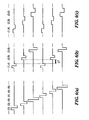
- Fig. 6(a) shows sequential pulses in conventional CIS
- Fig. 6(b) shows simultaneous pulses in a CI sequence
- Fig. 6(c) shows the CI sequence of Fig. 6(b) with increased pulse phase duration
- Fig. 7 shows a method of increasing the stimulation information rate
- Fig. 8 shows a method of decreasing stimulation power and voltage requirements.
- a simultaneous stimulation sequence such as a channel interaction (CI) sequence having simultaneous, sign-correlated pulses and channel interaction compensation, includes temporal gaps between pulses.
- the CI sequence may be, for example, based on a sequential stimulation sequence such that the CI pulse rate is substantially equal to the sequential stimulation sequence pulse rate.
- the CI pulse rate is increased by filling the temporal gaps between pulses with additional pulses, such that the information rate is increased.
- the pulse amplitudes of the CI sequence may be reduced without increasing the number of pulses per second, allowing for low power and low voltage implementations of standard sequential stimulation strategies. Details of illustrative embodiments are discussed below.
- the voltage drop across interface impedances Z 1 is reduced based on simultaneous stimulation of two or more channels. If two or more electrodes are stimulated simultaneously, then effects of spatial channel interaction can be exploited, as described below.
- Spatial channel interaction occurs when different stimulation electrodes (positioned in the scala tympani) are activated and there is considerable geometric overlapping of electrical fields at the location of the excitable nerve tissue. Thus the same neurons are activated, if different electrodes are stimulated. Stimulation of a particular electrode against a remote ground electrode (monopolar stimulation) causes an electrical potential within the scala tympani which can roughly be described by two decaying exponentials at both sides of the electrode, and the space constant (in humans) is typically ⁇ ⁇ 10 mm.
- the influence of spatial channel interaction is reduced by employing pulses which are not overlapping in time (interleaved sampling).
- the conductivity in the scala tympani here leads to a considerable spread and a de-focusing of the electrical field at the site of the excitable tissue.
- an additional effect occurs, if uncorrelated simultaneous stimulation of two or more electrodes against a remote ground electrode is considered.
- the conductivity represents a shunt conductance between active electrodes, which in general results in a mixture of constructive and destructive superposition of electrical fields at the position of the neurons. For example, if two simultaneous stimulation channels produce currents with equal amplitudes, but different signs, most of the current will flow through the shunt conductance and will not reach the intended neurons.
- Preferred embodiments of the invention utilize the simultaneous activation of two or more electrodes in the scala tympani against a remote reference electrode (monopolar electrode configuration). Furthermore, all pulses are exactly simultaneous, that is, positive and negative pulse-phases start and stop at the same time instants, respectively. In addition, all simultaneous phases have the same sign. As used herein, such simultaneous pulses are designated as "sign-correlated" pulses.
- Fig. 5 (a-b)
- Fig. 5(a) shows two (normalized) scala tympani potentials due to two sequentially applied stimulation pulses of equal amplitudes.
- the distance between the active electrodes is 12mm.
- 5(b) shows the resulting potential (solid line), if two stimulation pulses are applied simultaneously and after the amplitudes have been adapted using CIC, in accordance with an embodiment of the invention. Note that the peak potentials at the position of the electrodes have not been changed as compared to the upper plot. This curve is the result of the superposition of the two single potentials (dotted lines). Regarding the maximum amplitudes of the single potentials, it is clear that these are reduced as compared to the potentials of the Fig. 5(a) . In this example, the reduction is 23%.
- any stimulation strategy utilizing simultaneous stimulation in combination with CIC leads to an average reduction of stimulation power, if such a strategy is compared to standard CIS using the same number of stimulation pulses per second.
- the amount of average reduction depends on a variety of parameters, such as the number of channels used simultaneously, the distance between these channels, or the spatial decay constants.
- the amount of average reduction also depends on the probability distribution of the sequential amplitudes used as an input to CIC. Referring back to the example shown in Figs. 5 (a-b), the power consumption is reduced proportional to the reduction of the stimulation amplitudes, that is by 23%.
- the case of two equal sequential amplitudes represents the "best case” with respect to power saving effects.
- the "worst case” occurs, if one of the two sequential amplitudes is zero. Then CIC does not change these amplitudes, and therefore there is no power saving.
- FIG. 6(a) A CIC-based system is shown in Fig. 6(b) , in accordance with an embodiment of the invention.
- simultaneous, sign-correlated pulses occur. More particularly, each of the three electrode pairs (1,4), (2,5), and (3,6) are simultaneous, following the pattern, without limitation, of... (1,4) (2,5) (3,6) (1,4) ....
- Fig. 5(b) represents an example for such an electrode pair. Assuming that both systems utilize the same number of stimulation pulses per second and both systems use the same implant supply voltage, an average reduction of simulation power in the range of by ⁇ 15-20% can be expected.
- applying simultaneous pulses introduces a gap between pairs of simultaneous pulses.
- this gap can be closed by doubling the phase durations, as shown in Fig. 6c in accordance with an embodiment of the invention.
- the stimulation amplitude can be reduced by a factor 2.
- the phase durations of sequential pulses can be multiplied by N, and for equal charge per phase, the amplitudes can be divided by a factor N.
- This reduction in amplitudes can be exploited for a reduction of the implant supply voltage V CC , that is, the implant supply voltage can be divided by N. Since the same charge per phase is used as for simultaneous pulses with short phases, the overall stimulation power being proportional to the product of implant supply voltage and the mean stimulation amplitude is reduced by a factor N.
- Both the reduction of stimulation power and the reduction of the implant supply voltage represents substantial advantages, in particular with respect to a totally implantable cochlear implant (TICI).
- a low power consumption is a general advantage with respect to the limited power resources in a TICI
- the voltage produced by rechargeable batteries can directly be used directly.
- lithium polymer secondary batteries using lithium cobalt oxide (LiCoO 2 ) produce 3.65V.
- Such a supply voltage would not be sufficient for the implementation of the standard CIS-strategy. Therefore voltage doubling or similar circuits are necessary, and such circuits considerably increase size and power consumption of a TICI.
- Fig. 7 shows a method of increasing the stimulation information rate.
- the method may be implemented, without limitation, by a stimulation system that includes: a stimulator 105 having a multi-channel electrode array 107 utilizing a monopolar electrode configuration; and a controller, such as processor 101 for controlling the stimulator 105, as shown in Fig. 1 .
- Controller may include, without limitation, various circuitry, and/or memory and be appropriately pre-programmed or configured to be loaded with an appropriate program.
- Memory may include, for example, a diskette, a fixed disk, a Compact Disk (CD), Read Only Memory (ROM), Erasable Programmable Read-Only Memory (EPROM), and/or Random Access Memory (RAM).
- CD Compact Disk
- ROM Read Only Memory
- EPROM Erasable Programmable Read-Only Memory
- RAM Random Access Memory
- various parts of the system may be implantable, and may be part of a cochlear implant that stimulates the acoustic nerve.
- the controller determines a channel interaction (CI) sequence using simultaneous, sign-correlated pulses and channel interaction compensation.
- the CI sequence has a CI pulse rate and a CI mean pulse amplitude, and produces resulting potentials that are substantially equal to desired potentials at given positions relative to the multi-channel array.
- the controller determines the CI sequence by determining a sequential stimulation sequence, such as a CIS sequence, having a sequential stimulation sequence pulse rate and sequential stimulation sequence mean pulse amplitude for producing desired potentials at given positions relative to the multi-channel electrode array.
- the controller then converts the sequential stimulation sequence into a channel interaction (CI) sequence that uses simultaneous, sign-correlated pulses and channel interaction compensation, so as to produce resulting potentials that are substantially equal to the desired potentials at the given positions.
- CI channel interaction
- each of the CI pulse amplitudes is typically less than the amplitude needed to activate an electrode in the multi-channel electrode array using the sequential stimulation sequence, as simultaneous CI pulses are added to produce the desired potentials.
- Such a converted CI sequence, or an initially determined CI sequence may include temporal gaps between pulses. This can be advantageously exploited by the controller, for example, by increasing the CI pulse rate such that the temporal gap between pulses is decreased, as shown in step 704 of Fig. 7 .
- the increased stimulation rate allows for implantation of fine structure stimulation strategies, as described above.
- the controller then simultaneously activates at least two electrodes as a function of the determined CI pulse amplitudes to achieve, via spatial channel interaction, the desired potential at the given position.
- Fig. 8 shows a method of decreasing stimulation power and voltage requirements.
- the controller determines a channel interaction (CI) sequence using simultaneous, sign-correlated pulses and channel interaction compensation, similar to step 703 in Fig. 7 .
- the pulse amplitudes of the CI sequence are reduced while increasing pulse phase duration, such that charge per pulse remains substantially unchanged and the temporal gap between pulses is decreased.
- the disclosed method may be implemented as a computer program product for use with a computer system.
- Such implementation may include a series of computer instructions fixed cither on a tangible-medium, such as a computer readable media (e.g., a diskette, CD-ROM. ROM, or fixed disk) or transmittable to a computer system, via a modcrn or other interface device, such a, a communications adapter connected to a network over a medium.
- Medium may be either a tangible medium (e.g., optical or analog communications lines) or a medium implemented with wireless techniques (e.g., microwave, infrared or other transmission techniques).
- the series of computer instructions embodies all or part of the functionality previously described herein with respect to the system.
- Such computer instructions can be written in a number of programming languages for use with many computer architectures.or operating systems. Furthermore, such instructions may be stored in any memory device, such as semiconductor, magnetic, optical or other memory devices, And may be transmitted using any communications technology, such as optical, infrared, or microwave, or other transmission technologies. It is expected that such a computer program product may be distributed as a removable media with accompanying printed or electronic documentation (e.g., shrink wrapped software), preloaded with a computer system (e.g., on system ROM or fixed disk), or distributed from a server or electronic bulletin board over the network (e.g., the Internet or World Wide Web).
- printed or electronic documentation e.g., shrink wrapped software
Landscapes
- Health & Medical Sciences (AREA)
- Otolaryngology (AREA)
- Engineering & Computer Science (AREA)
- General Health & Medical Sciences (AREA)
- Nuclear Medicine, Radiotherapy & Molecular Imaging (AREA)
- Radiology & Medical Imaging (AREA)
- Life Sciences & Earth Sciences (AREA)
- Animal Behavior & Ethology (AREA)
- Biomedical Technology (AREA)
- Public Health (AREA)
- Veterinary Medicine (AREA)
- Neurosurgery (AREA)
- Physics & Mathematics (AREA)
- Acoustics & Sound (AREA)
- Signal Processing (AREA)
- Cardiology (AREA)
- Heart & Thoracic Surgery (AREA)
- Electrotherapy Devices (AREA)
- Prostheses (AREA)
Claims (6)
- Système de stimulation comprenant :un stimulateur comprenant un réseau d'électrodes multicanal ayant une configuration d'électrodes mono-polaires ;un processeur couplé fonctionnellement au stimulateur, le processeur étant agencé pour déterminer une séquence d'interaction de canaux (CI), la séquence CI ayant une fréquence d'impulsions CI et une amplitude moyenne d'impulsion CI, la séquence CI étant destinée à produire des potentiels résultants qui sont sensiblement égaux à des potentiels souhaités à des positions données par rapport au réseau multicanal, la séquence CI comprenant des intervalles temporels entre les impulsions,caractérisé en ce que le processeur détermine la séquence d'interaction de canaux utilisant des impulsions simultanées à signe corrélé et une compensation d'interaction de canaux et est en outre agencé pour réduire l'amplitude d'impulsion de la séquence CI tout en augmentant la durée de phase d'impulsion, de telle sorte que la charge par impulsion reste sensiblement inchangée et que l'intervalle temporel entre impulsions est diminué.
- Système selon la revendication 1, dans lequel le stimulateur fait partie d'un implant cochléaire.
- Système selon la revendication 1, dans lequel le processeur est agencé pour activer simultanément au moins deux électrodes du réseau d'électrodes multicanal en fonction de la séquence CI pour obtenir le potentiel souhaité à la position donnée.
- Système selon la revendication 1, dans lequel la séquence CI comprend des impulsions de courant biphase symétriques.
- Produit programme d'ordinateur adapté pour activer simultanément des électrodes dans un réseau d'électrodes multicanal ayant une configuration d'électrodes mono-polaires, le produit programme d'ordinateur comprenant un support utilisable par un ordinateur portant sur lui du code de programme lisible par un ordinateur, le code de programme lisible par un ordinateur comprenant :du code de programme pour déterminer, lorsqu'il est exécuté par un processeur d'un système de stimulation selon la revendication 1, une séquence d'interaction de canaux (CI) utilisant des impulsions simultanées à signe corrélé et une compensation d'interaction de canaux, la séquence CI ayant une fréquence d'impulsions CI et une amplitude moyenne d'impulsion CI, la séquence CI étant destinée à produire des potentiels résultants qui sont sensiblement égaux à des potentiels souhaités à des positions données par rapport au réseau multicanal, la séquence CI comprenant des intervalles temporels entre les impulsions,caractérisé en ce que le produit programme d'ordinateur comprend en outre du code de programme pour réduire l'amplitude d'impulsion de la séquence CI tout en augmentant la durée de phase d'impulsion, de telle sorte que la charge par impulsion reste sensiblement inchangée et que l'intervalle temporel entre impulsions est diminué.
- Produit programme d'ordinateur selon la revendication 5, comprenant en outre du code de programme pour activer simultanément au moins deux électrodes du réseau d'électrodes multicanal en fonction de la séquence CI pour obtenir le potentiel souhaité à la position donnée.
Priority Applications (1)
| Application Number | Priority Date | Filing Date | Title |
|---|---|---|---|
| EP11165881.1A EP2364749B1 (fr) | 2005-04-07 | 2006-04-06 | Stimulation simultanée pour faible consommation électrique |
Applications Claiming Priority (2)
| Application Number | Priority Date | Filing Date | Title |
|---|---|---|---|
| US11/101,149 US7917224B2 (en) | 1999-07-21 | 2005-04-07 | Simultaneous stimulation for low power consumption |
| PCT/IB2006/002510 WO2006136961A2 (fr) | 2005-04-07 | 2006-04-06 | Combinaisons cardio-vasculaires a inhibiteurs d'ace et d'hmg coa |
Related Child Applications (2)
| Application Number | Title | Priority Date | Filing Date |
|---|---|---|---|
| EP11165881.1A Division EP2364749B1 (fr) | 2005-04-07 | 2006-04-06 | Stimulation simultanée pour faible consommation électrique |
| EP11165881.1 Division-Into | 2011-05-12 |
Publications (2)
| Publication Number | Publication Date |
|---|---|
| EP1866027A2 EP1866027A2 (fr) | 2007-12-19 |
| EP1866027B1 true EP1866027B1 (fr) | 2013-06-26 |
Family
ID=37561666
Family Applications (2)
| Application Number | Title | Priority Date | Filing Date |
|---|---|---|---|
| EP11165881.1A Active EP2364749B1 (fr) | 2005-04-07 | 2006-04-06 | Stimulation simultanée pour faible consommation électrique |
| EP06795473.5A Active EP1866027B1 (fr) | 2005-04-07 | 2006-04-06 | Combinaisons cardio-vasculaires à inhibiteurs d'ace et d'hmg coa |
Family Applications Before (1)
| Application Number | Title | Priority Date | Filing Date |
|---|---|---|---|
| EP11165881.1A Active EP2364749B1 (fr) | 2005-04-07 | 2006-04-06 | Stimulation simultanée pour faible consommation électrique |
Country Status (9)
| Country | Link |
|---|---|
| US (2) | US7917224B2 (fr) |
| EP (2) | EP2364749B1 (fr) |
| JP (1) | JP5047157B2 (fr) |
| KR (1) | KR101280693B1 (fr) |
| CN (1) | CN101160151B (fr) |
| AU (1) | AU2006260598B2 (fr) |
| CA (1) | CA2602895C (fr) |
| RU (1) | RU2440156C2 (fr) |
| WO (1) | WO2006136961A2 (fr) |
Families Citing this family (23)
| Publication number | Priority date | Publication date | Assignee | Title |
|---|---|---|---|---|
| US7917224B2 (en) * | 1999-07-21 | 2011-03-29 | Med-El Elektromedizinische Geraete Gmbh | Simultaneous stimulation for low power consumption |
| WO2001013991A1 (fr) | 1999-08-26 | 2001-03-01 | Med-El Elektromedizinische Geräte GmbH | Stimulation nerveuse electrique fondee sur des sequences d'echantillonnage specifiques a une voie |
| US8165686B2 (en) | 1999-08-26 | 2012-04-24 | Med-El Elektromedizinische Geraete Gmbh | Simultaneous intracochlear stimulation |
| EP2594315A1 (fr) * | 2007-07-10 | 2013-05-22 | Sapiens Steering Brain Stimulation B.V. | Système de neurostimulation |
| CN101743036B (zh) * | 2007-07-13 | 2014-07-23 | Med-El电气医疗器械有限公司 | 具有宽带低频滤波器的电神经刺激 |
| AU2008298928B2 (en) * | 2007-09-11 | 2012-09-20 | Med-El Elektromedizinische Geraete Gmbh | Simultaneous intracochlear stimulation |
| AU2009233699B2 (en) * | 2008-04-08 | 2014-05-15 | Med-El Elektromedizinische Geraete Gmbh | Electrical stimulation of the acoustic nerve with coherent fine structure |
| US8644944B2 (en) | 2009-08-03 | 2014-02-04 | Cochlear Limited | Implant stimulation device |
| AU2009222439B2 (en) | 2009-09-28 | 2011-07-21 | Cochlear Limited | Method and circuitry for measurement and control of stimulation current |
| EP2542301B1 (fr) | 2010-03-04 | 2014-03-12 | Fraunhofer Gesellschaft zur Förderung der angewandten Forschung e.V. | Production de signal de stimulation par électrode dans une prothèse auditive neurale |
| WO2012112383A1 (fr) | 2011-02-14 | 2012-08-23 | Med-Elektromedizinische Geraete Gmbh | Amélioration de la transmission de structure à réglage de précision pour un système d'implant auditif |
| AU2016213770B2 (en) * | 2011-05-13 | 2017-10-19 | Med-El Elektromedizinische Geraete Gmbh | Optimal model constants for simultaneous stimulation with channel interaction compensation |
| CN103533986B (zh) * | 2011-05-13 | 2016-09-14 | Med-El电气医疗器械有限公司 | 具有通道交互补偿的同时刺激的最佳模型常数 |
| CN104661700B (zh) * | 2012-08-27 | 2016-09-28 | Med-El电气医疗器械有限公司 | 听力植入物中的瞬变声音的减小 |
| US9042994B2 (en) | 2012-10-31 | 2015-05-26 | Med-El Elektromedizinische Geraete Gmbh | Temporal coding for hearing implants |
| US9295837B2 (en) | 2013-07-22 | 2016-03-29 | Med-El Elektromedizinische Geraete Gmbh | Optimized channel configuration based on spatial profiles |
| US9999769B2 (en) | 2014-03-10 | 2018-06-19 | Cisco Technology, Inc. | Excitation modeling and matching |
| DE102015104614A1 (de) * | 2015-03-26 | 2016-09-29 | Med-El Elektromedizinische Geräte GmbH | Vorrichtung und Verfahren zur elektrischen Stimulation mit Hilfe eines Cochlea-Implantats |
| US10342975B2 (en) * | 2015-09-14 | 2019-07-09 | Cochlear Limited | Micro-charge stimulation |
| CN107121605A (zh) * | 2017-04-21 | 2017-09-01 | 浙江诺尔康神经电子科技股份有限公司 | 一种电子耳蜗刺激器芯片防静电测试方法 |
| WO2019045747A1 (fr) * | 2017-08-31 | 2019-03-07 | Advanced Bionics Ag | Systèmes et procédés de localisation d'électrode destinés à être utilisés chez un patient à implant cochléaire |
| CN108521273B (zh) * | 2018-04-04 | 2022-03-01 | 四川新先达测控技术有限公司 | 脉冲信号处理方法、装置及用户终端 |
| RU2722852C1 (ru) * | 2019-12-02 | 2020-06-04 | Общество с ограниченной ответственностью (ООО) "Производственная компания "АЛЬТОНИКА" (ООО "ПК "Альтоника") | Устройство кохлеарной имплантации |
Family Cites Families (29)
| Publication number | Priority date | Publication date | Assignee | Title |
|---|---|---|---|---|
| US3918042A (en) | 1974-04-29 | 1975-11-04 | Motorola Inc | Delta modulator having increased dynamic range |
| US4156969A (en) * | 1976-11-19 | 1979-06-05 | Werber Fred W K R | Garment designing aid |
| US4284856A (en) | 1979-09-24 | 1981-08-18 | Hochmair Ingeborg | Multi-frequency system and method for enhancing auditory stimulation and the like |
| DE3008677C2 (de) | 1980-03-06 | 1983-08-25 | Siemens AG, 1000 Berlin und 8000 München | Hörprothese zur elektrischen Stimulation des Hörnervs |
| CA1189147A (fr) * | 1980-12-12 | 1985-06-18 | James F. Patrick | Amelioration dans les dispositifs de traitement de la parole |
| US4829299A (en) | 1987-09-25 | 1989-05-09 | Dolby Laboratories Licensing Corporation | Adaptive-filter single-bit digital encoder and decoder and adaptation control circuit responsive to bit-stream loading |
| DE3821970C1 (fr) | 1988-06-29 | 1989-12-14 | Ernst-Ludwig Von Dr. 8137 Berg De Wallenberg-Pachaly | |
| US5603726A (en) | 1989-09-22 | 1997-02-18 | Alfred E. Mann Foundation For Scientific Research | Multichannel cochlear implant system including wearable speech processor |
| US5938691A (en) | 1989-09-22 | 1999-08-17 | Alfred E. Mann Foundation | Multichannel implantable cochlear stimulator |
| US5151158A (en) | 1991-07-16 | 1992-09-29 | Stone & Webster Engineering Corporation | Thermal cracking furnace |
| US5549658A (en) | 1994-10-24 | 1996-08-27 | Advanced Bionics Corporation | Four-Channel cochlear system with a passive, non-hermetically sealed implant |
| US5601617A (en) | 1995-04-26 | 1997-02-11 | Advanced Bionics Corporation | Multichannel cochlear prosthesis with flexible control of stimulus waveforms |
| US6219580B1 (en) | 1995-04-26 | 2001-04-17 | Advanced Bionics Corporation | Multichannel cochlear prosthesis with flexible control of stimulus waveforms |
| US5824022A (en) | 1996-03-07 | 1998-10-20 | Advanced Bionics Corporation | Cochlear stimulation system employing behind-the-ear speech processor with remote control |
| US5957958A (en) * | 1997-01-15 | 1999-09-28 | Advanced Bionics Corporation | Implantable electrode arrays |
| JP4293639B2 (ja) | 1997-05-01 | 2009-07-08 | メド−エル・エレクトロメディツィニシェ・ゲラーテ・ゲーエムベーハー | 低電力デジタルフィルタ装置及び方法 |
| WO1999020341A1 (fr) * | 1997-10-16 | 1999-04-29 | Electrologic Of America, Inc. | Procede et appareil de therapie par stimulation electrique |
| AU754753B2 (en) | 1998-01-12 | 2002-11-21 | Toumaz Technology Ltd | Audio signal processors |
| US6078838A (en) | 1998-02-13 | 2000-06-20 | University Of Iowa Research Foundation | Pseudospontaneous neural stimulation system and method |
| JP2002509761A (ja) | 1998-04-01 | 2002-04-02 | サー・ジェイムズ・エイチ・ドイル | 多重チャネルのインプラント可能な内耳刺激器 |
| US6175767B1 (en) | 1998-04-01 | 2001-01-16 | James H. Doyle, Sr. | Multichannel implantable inner ear stimulator |
| US6289247B1 (en) | 1998-06-02 | 2001-09-11 | Advanced Bionics Corporation | Strategy selector for multichannel cochlear prosthesis |
| US7917224B2 (en) * | 1999-07-21 | 2011-03-29 | Med-El Elektromedizinische Geraete Gmbh | Simultaneous stimulation for low power consumption |
| ES2219367T3 (es) | 1999-07-21 | 2004-12-01 | Med-El Elektromedizinische Gerate Gmbh | Implante coclear multicanal con telemetria de respuesta neuronal. |
| US8165686B2 (en) * | 1999-08-26 | 2012-04-24 | Med-El Elektromedizinische Geraete Gmbh | Simultaneous intracochlear stimulation |
| WO2001013991A1 (fr) | 1999-08-26 | 2001-03-01 | Med-El Elektromedizinische Geräte GmbH | Stimulation nerveuse electrique fondee sur des sequences d'echantillonnage specifiques a une voie |
| CA2381725C (fr) | 1999-09-16 | 2008-01-22 | Advanced Bionics N.V. | Implant cochleaire |
| AU2001251144A1 (en) | 2000-03-31 | 2001-10-15 | Advanced Bionics Corporation | High contact count, sub-miniature, fully implantable cochlear prosthesis |
| EP1722852B1 (fr) | 2004-03-08 | 2015-06-03 | MED-EL Elektromedizinische Geräte GmbH | Stimulation electrique du nerf auditif fondee sur des groupes selectionnes |
-
2005
- 2005-04-07 US US11/101,149 patent/US7917224B2/en not_active Expired - Fee Related
-
2006
- 2006-04-06 AU AU2006260598A patent/AU2006260598B2/en active Active
- 2006-04-06 EP EP11165881.1A patent/EP2364749B1/fr active Active
- 2006-04-06 KR KR1020077022786A patent/KR101280693B1/ko active IP Right Grant
- 2006-04-06 CN CN2006800114631A patent/CN101160151B/zh active Active
- 2006-04-06 CA CA2602895A patent/CA2602895C/fr active Active
- 2006-04-06 RU RU2007140927/14A patent/RU2440156C2/ru not_active Application Discontinuation
- 2006-04-06 JP JP2008504873A patent/JP5047157B2/ja active Active
- 2006-04-06 WO PCT/IB2006/002510 patent/WO2006136961A2/fr active Application Filing
- 2006-04-06 EP EP06795473.5A patent/EP1866027B1/fr active Active
-
2010
- 2010-12-01 US US12/957,974 patent/US8428742B2/en not_active Expired - Fee Related
Also Published As
| Publication number | Publication date |
|---|---|
| WO2006136961A3 (fr) | 2007-04-05 |
| RU2007140927A (ru) | 2009-05-20 |
| AU2006260598A1 (en) | 2006-12-28 |
| US20050203590A1 (en) | 2005-09-15 |
| WO2006136961A8 (fr) | 2008-02-21 |
| US8428742B2 (en) | 2013-04-23 |
| US20110077711A1 (en) | 2011-03-31 |
| EP1866027A2 (fr) | 2007-12-19 |
| US7917224B2 (en) | 2011-03-29 |
| JP2008534210A (ja) | 2008-08-28 |
| EP2364749A1 (fr) | 2011-09-14 |
| KR20080005921A (ko) | 2008-01-15 |
| KR101280693B1 (ko) | 2013-07-02 |
| AU2006260598B2 (en) | 2010-10-14 |
| EP2364749B1 (fr) | 2015-10-21 |
| JP5047157B2 (ja) | 2012-10-10 |
| RU2440156C2 (ru) | 2012-01-20 |
| CA2602895C (fr) | 2014-08-19 |
| CA2602895A1 (fr) | 2006-12-28 |
| CN101160151A (zh) | 2008-04-09 |
| WO2006136961A2 (fr) | 2006-12-28 |
| CN101160151B (zh) | 2013-03-27 |
Similar Documents
| Publication | Publication Date | Title |
|---|---|---|
| EP1866027B1 (fr) | Combinaisons cardio-vasculaires à inhibiteurs d'ace et d'hmg coa | |
| US7283876B2 (en) | Electrical stimulation of the acoustic nerve based on selected groups | |
| US7937157B2 (en) | Electrical nerve stimulation based on channel specific sequences | |
| US8948877B2 (en) | Cochlear implant stimulation with low frequency channel privilege | |
| US7941223B2 (en) | Cochlear implant stimulation with variable number of electrodes | |
| AU2008276262B2 (en) | Electrical nerve stimulation with broad band low frequency filter | |
| US7899547B1 (en) | Level-dependent stimulation methods and systems |
Legal Events
| Date | Code | Title | Description |
|---|---|---|---|
| PUAI | Public reference made under article 153(3) epc to a published international application that has entered the european phase |
Free format text: ORIGINAL CODE: 0009012 |
|
| 17P | Request for examination filed |
Effective date: 20070925 |
|
| AK | Designated contracting states |
Kind code of ref document: A2 Designated state(s): AT BE BG CH CY CZ DE DK EE ES FI FR GB GR HU IE IS IT LI LT LU LV MC NL PL PT RO SE SI SK TR |
|
| R17D | Deferred search report published (corrected) |
Effective date: 20080221 |
|
| R17P | Request for examination filed (corrected) |
Effective date: 20070925 |
|
| RTI1 | Title (correction) |
Free format text: SIMULTANEOUS STIMULATION FOR LOW POWER CONSUMPTION |
|
| DAX | Request for extension of the european patent (deleted) | ||
| 17Q | First examination report despatched |
Effective date: 20090513 |
|
| GRAP | Despatch of communication of intention to grant a patent |
Free format text: ORIGINAL CODE: EPIDOSNIGR1 |
|
| GRAS | Grant fee paid |
Free format text: ORIGINAL CODE: EPIDOSNIGR3 |
|
| RAP1 | Party data changed (applicant data changed or rights of an application transferred) |
Owner name: MED-EL ELEKTROMEDIZINISCHE GERAETE GMBH |
|
| GRAA | (expected) grant |
Free format text: ORIGINAL CODE: 0009210 |
|
| AK | Designated contracting states |
Kind code of ref document: B1 Designated state(s): AT BE BG CH CY CZ DE DK EE ES FI FR GB GR HU IE IS IT LI LT LU LV MC NL PL PT RO SE SI SK TR |
|
| REG | Reference to a national code |
Ref country code: GB Ref legal event code: FG4D |
|
| REG | Reference to a national code |
Ref country code: CH Ref legal event code: NV Representative=s name: E. BLUM AND CO. AG PATENT- UND MARKENANWAELTE , CH Ref country code: CH Ref legal event code: EP |
|
| REG | Reference to a national code |
Ref country code: AT Ref legal event code: REF Ref document number: 618422 Country of ref document: AT Kind code of ref document: T Effective date: 20130715 |
|
| REG | Reference to a national code |
Ref country code: IE Ref legal event code: FG4D |
|
| REG | Reference to a national code |
Ref country code: DE Ref legal event code: R096 Ref document number: 602006037017 Country of ref document: DE Effective date: 20130822 |
|
| PG25 | Lapsed in a contracting state [announced via postgrant information from national office to epo] |
Ref country code: FI Free format text: LAPSE BECAUSE OF FAILURE TO SUBMIT A TRANSLATION OF THE DESCRIPTION OR TO PAY THE FEE WITHIN THE PRESCRIBED TIME-LIMIT Effective date: 20130626 Ref country code: GR Free format text: LAPSE BECAUSE OF FAILURE TO SUBMIT A TRANSLATION OF THE DESCRIPTION OR TO PAY THE FEE WITHIN THE PRESCRIBED TIME-LIMIT Effective date: 20130927 Ref country code: SI Free format text: LAPSE BECAUSE OF FAILURE TO SUBMIT A TRANSLATION OF THE DESCRIPTION OR TO PAY THE FEE WITHIN THE PRESCRIBED TIME-LIMIT Effective date: 20130626 Ref country code: LT Free format text: LAPSE BECAUSE OF FAILURE TO SUBMIT A TRANSLATION OF THE DESCRIPTION OR TO PAY THE FEE WITHIN THE PRESCRIBED TIME-LIMIT Effective date: 20130626 Ref country code: SE Free format text: LAPSE BECAUSE OF FAILURE TO SUBMIT A TRANSLATION OF THE DESCRIPTION OR TO PAY THE FEE WITHIN THE PRESCRIBED TIME-LIMIT Effective date: 20130626 |
|
| REG | Reference to a national code |
Ref country code: AT Ref legal event code: MK05 Ref document number: 618422 Country of ref document: AT Kind code of ref document: T Effective date: 20130626 |
|
| REG | Reference to a national code |
Ref country code: LT Ref legal event code: MG4D |
|
| PG25 | Lapsed in a contracting state [announced via postgrant information from national office to epo] |
Ref country code: BG Free format text: LAPSE BECAUSE OF FAILURE TO SUBMIT A TRANSLATION OF THE DESCRIPTION OR TO PAY THE FEE WITHIN THE PRESCRIBED TIME-LIMIT Effective date: 20130926 |
|
| REG | Reference to a national code |
Ref country code: NL Ref legal event code: VDEP Effective date: 20130626 |
|
| PG25 | Lapsed in a contracting state [announced via postgrant information from national office to epo] |
Ref country code: LV Free format text: LAPSE BECAUSE OF FAILURE TO SUBMIT A TRANSLATION OF THE DESCRIPTION OR TO PAY THE FEE WITHIN THE PRESCRIBED TIME-LIMIT Effective date: 20130626 |
|
| PG25 | Lapsed in a contracting state [announced via postgrant information from national office to epo] |
Ref country code: CZ Free format text: LAPSE BECAUSE OF FAILURE TO SUBMIT A TRANSLATION OF THE DESCRIPTION OR TO PAY THE FEE WITHIN THE PRESCRIBED TIME-LIMIT Effective date: 20130626 Ref country code: EE Free format text: LAPSE BECAUSE OF FAILURE TO SUBMIT A TRANSLATION OF THE DESCRIPTION OR TO PAY THE FEE WITHIN THE PRESCRIBED TIME-LIMIT Effective date: 20130626 Ref country code: CY Free format text: LAPSE BECAUSE OF FAILURE TO SUBMIT A TRANSLATION OF THE DESCRIPTION OR TO PAY THE FEE WITHIN THE PRESCRIBED TIME-LIMIT Effective date: 20130703 Ref country code: AT Free format text: LAPSE BECAUSE OF FAILURE TO SUBMIT A TRANSLATION OF THE DESCRIPTION OR TO PAY THE FEE WITHIN THE PRESCRIBED TIME-LIMIT Effective date: 20130626 Ref country code: IS Free format text: LAPSE BECAUSE OF FAILURE TO SUBMIT A TRANSLATION OF THE DESCRIPTION OR TO PAY THE FEE WITHIN THE PRESCRIBED TIME-LIMIT Effective date: 20131026 Ref country code: BE Free format text: LAPSE BECAUSE OF FAILURE TO SUBMIT A TRANSLATION OF THE DESCRIPTION OR TO PAY THE FEE WITHIN THE PRESCRIBED TIME-LIMIT Effective date: 20130626 Ref country code: SK Free format text: LAPSE BECAUSE OF FAILURE TO SUBMIT A TRANSLATION OF THE DESCRIPTION OR TO PAY THE FEE WITHIN THE PRESCRIBED TIME-LIMIT Effective date: 20130626 Ref country code: PT Free format text: LAPSE BECAUSE OF FAILURE TO SUBMIT A TRANSLATION OF THE DESCRIPTION OR TO PAY THE FEE WITHIN THE PRESCRIBED TIME-LIMIT Effective date: 20131028 |
|
| PG25 | Lapsed in a contracting state [announced via postgrant information from national office to epo] |
Ref country code: PL Free format text: LAPSE BECAUSE OF FAILURE TO SUBMIT A TRANSLATION OF THE DESCRIPTION OR TO PAY THE FEE WITHIN THE PRESCRIBED TIME-LIMIT Effective date: 20130626 Ref country code: RO Free format text: LAPSE BECAUSE OF FAILURE TO SUBMIT A TRANSLATION OF THE DESCRIPTION OR TO PAY THE FEE WITHIN THE PRESCRIBED TIME-LIMIT Effective date: 20130626 Ref country code: ES Free format text: LAPSE BECAUSE OF FAILURE TO SUBMIT A TRANSLATION OF THE DESCRIPTION OR TO PAY THE FEE WITHIN THE PRESCRIBED TIME-LIMIT Effective date: 20131007 Ref country code: NL Free format text: LAPSE BECAUSE OF FAILURE TO SUBMIT A TRANSLATION OF THE DESCRIPTION OR TO PAY THE FEE WITHIN THE PRESCRIBED TIME-LIMIT Effective date: 20130626 |
|
| PG25 | Lapsed in a contracting state [announced via postgrant information from national office to epo] |
Ref country code: CY Free format text: LAPSE BECAUSE OF FAILURE TO SUBMIT A TRANSLATION OF THE DESCRIPTION OR TO PAY THE FEE WITHIN THE PRESCRIBED TIME-LIMIT Effective date: 20130626 |
|
| PG25 | Lapsed in a contracting state [announced via postgrant information from national office to epo] |
Ref country code: DK Free format text: LAPSE BECAUSE OF FAILURE TO SUBMIT A TRANSLATION OF THE DESCRIPTION OR TO PAY THE FEE WITHIN THE PRESCRIBED TIME-LIMIT Effective date: 20130626 |
|
| PLBE | No opposition filed within time limit |
Free format text: ORIGINAL CODE: 0009261 |
|
| STAA | Information on the status of an ep patent application or granted ep patent |
Free format text: STATUS: NO OPPOSITION FILED WITHIN TIME LIMIT |
|
| PG25 | Lapsed in a contracting state [announced via postgrant information from national office to epo] |
Ref country code: IT Free format text: LAPSE BECAUSE OF FAILURE TO SUBMIT A TRANSLATION OF THE DESCRIPTION OR TO PAY THE FEE WITHIN THE PRESCRIBED TIME-LIMIT Effective date: 20130626 |
|
| 26N | No opposition filed |
Effective date: 20140327 |
|
| REG | Reference to a national code |
Ref country code: DE Ref legal event code: R097 Ref document number: 602006037017 Country of ref document: DE Effective date: 20140327 |
|
| PG25 | Lapsed in a contracting state [announced via postgrant information from national office to epo] |
Ref country code: LU Free format text: LAPSE BECAUSE OF FAILURE TO SUBMIT A TRANSLATION OF THE DESCRIPTION OR TO PAY THE FEE WITHIN THE PRESCRIBED TIME-LIMIT Effective date: 20140406 Ref country code: MC Free format text: LAPSE BECAUSE OF FAILURE TO SUBMIT A TRANSLATION OF THE DESCRIPTION OR TO PAY THE FEE WITHIN THE PRESCRIBED TIME-LIMIT Effective date: 20130626 |
|
| REG | Reference to a national code |
Ref country code: IE Ref legal event code: MM4A |
|
| PG25 | Lapsed in a contracting state [announced via postgrant information from national office to epo] |
Ref country code: IE Free format text: LAPSE BECAUSE OF NON-PAYMENT OF DUE FEES Effective date: 20140406 |
|
| REG | Reference to a national code |
Ref country code: FR Ref legal event code: PLFP Year of fee payment: 11 |
|
| PG25 | Lapsed in a contracting state [announced via postgrant information from national office to epo] |
Ref country code: HU Free format text: LAPSE BECAUSE OF FAILURE TO SUBMIT A TRANSLATION OF THE DESCRIPTION OR TO PAY THE FEE WITHIN THE PRESCRIBED TIME-LIMIT; INVALID AB INITIO Effective date: 20060406 Ref country code: TR Free format text: LAPSE BECAUSE OF FAILURE TO SUBMIT A TRANSLATION OF THE DESCRIPTION OR TO PAY THE FEE WITHIN THE PRESCRIBED TIME-LIMIT Effective date: 20130626 |
|
| REG | Reference to a national code |
Ref country code: FR Ref legal event code: PLFP Year of fee payment: 12 |
|
| REG | Reference to a national code |
Ref country code: FR Ref legal event code: PLFP Year of fee payment: 13 |
|
| PGFP | Annual fee paid to national office [announced via postgrant information from national office to epo] |
Ref country code: GB Payment date: 20240423 Year of fee payment: 19 |
|
| PGFP | Annual fee paid to national office [announced via postgrant information from national office to epo] |
Ref country code: DE Payment date: 20240429 Year of fee payment: 19 |
|
| PGFP | Annual fee paid to national office [announced via postgrant information from national office to epo] |
Ref country code: CH Payment date: 20240501 Year of fee payment: 19 |
|
| PGFP | Annual fee paid to national office [announced via postgrant information from national office to epo] |
Ref country code: FR Payment date: 20240430 Year of fee payment: 19 |