EP1865738B1 - Procédé pour affecter des ressources radio de canaux physiques dans une liaison montante et émetteur pour appareils mobiles - Google Patents
Procédé pour affecter des ressources radio de canaux physiques dans une liaison montante et émetteur pour appareils mobiles Download PDFInfo
- Publication number
- EP1865738B1 EP1865738B1 EP06730060.8A EP06730060A EP1865738B1 EP 1865738 B1 EP1865738 B1 EP 1865738B1 EP 06730060 A EP06730060 A EP 06730060A EP 1865738 B1 EP1865738 B1 EP 1865738B1
- Authority
- EP
- European Patent Office
- Prior art keywords
- channel
- frequency
- shared
- band
- shared data
- Prior art date
- Legal status (The legal status is an assumption and is not a legal conclusion. Google has not performed a legal analysis and makes no representation as to the accuracy of the status listed.)
- Active
Links
- 238000000034 method Methods 0.000 title claims description 22
- 230000005540 biological transmission Effects 0.000 claims description 43
- 238000001228 spectrum Methods 0.000 claims description 28
- 238000004891 communication Methods 0.000 claims description 20
- 238000010586 diagram Methods 0.000 description 27
- 230000000694 effects Effects 0.000 description 13
- 230000007274 generation of a signal involved in cell-cell signaling Effects 0.000 description 10
- 230000007480 spreading Effects 0.000 description 8
- 238000012545 processing Methods 0.000 description 7
- 238000006243 chemical reaction Methods 0.000 description 6
- 230000003247 decreasing effect Effects 0.000 description 5
- 108010003272 Hyaluronate lyase Proteins 0.000 description 4
- 230000001419 dependent effect Effects 0.000 description 4
- 239000000969 carrier Substances 0.000 description 3
- 230000006866 deterioration Effects 0.000 description 3
- 238000005562 fading Methods 0.000 description 3
- 230000006872 improvement Effects 0.000 description 3
- 238000013507 mapping Methods 0.000 description 3
- 238000005259 measurement Methods 0.000 description 3
- 230000007423 decrease Effects 0.000 description 2
- 230000001934 delay Effects 0.000 description 2
- 201000002569 3-methylglutaconic aciduria type 5 Diseases 0.000 description 1
- 230000003044 adaptive effect Effects 0.000 description 1
- 230000008901 benefit Effects 0.000 description 1
- 125000004122 cyclic group Chemical group 0.000 description 1
- 238000011161 development Methods 0.000 description 1
- 238000001914 filtration Methods 0.000 description 1
- 238000012986 modification Methods 0.000 description 1
- 230000004048 modification Effects 0.000 description 1
- 230000006855 networking Effects 0.000 description 1
- 238000000926 separation method Methods 0.000 description 1
- 230000011664 signaling Effects 0.000 description 1
- 238000012546 transfer Methods 0.000 description 1
Images


Classifications
-
- H—ELECTRICITY
- H04—ELECTRIC COMMUNICATION TECHNIQUE
- H04L—TRANSMISSION OF DIGITAL INFORMATION, e.g. TELEGRAPHIC COMMUNICATION
- H04L5/00—Arrangements affording multiple use of the transmission path
- H04L5/0001—Arrangements for dividing the transmission path
- H04L5/0003—Two-dimensional division
- H04L5/0005—Time-frequency
-
- H—ELECTRICITY
- H04—ELECTRIC COMMUNICATION TECHNIQUE
- H04W—WIRELESS COMMUNICATION NETWORKS
- H04W72/00—Local resource management
- H04W72/50—Allocation or scheduling criteria for wireless resources
- H04W72/53—Allocation or scheduling criteria for wireless resources based on regulatory allocation policies
-
- H—ELECTRICITY
- H04—ELECTRIC COMMUNICATION TECHNIQUE
- H04L—TRANSMISSION OF DIGITAL INFORMATION, e.g. TELEGRAPHIC COMMUNICATION
- H04L5/00—Arrangements affording multiple use of the transmission path
- H04L5/0001—Arrangements for dividing the transmission path
- H04L5/0003—Two-dimensional division
- H04L5/0005—Time-frequency
- H04L5/0007—Time-frequency the frequencies being orthogonal, e.g. OFDM(A), DMT
-
- H—ELECTRICITY
- H04—ELECTRIC COMMUNICATION TECHNIQUE
- H04L—TRANSMISSION OF DIGITAL INFORMATION, e.g. TELEGRAPHIC COMMUNICATION
- H04L5/00—Arrangements affording multiple use of the transmission path
- H04L5/0001—Arrangements for dividing the transmission path
- H04L5/0014—Three-dimensional division
- H04L5/0016—Time-frequency-code
-
- H—ELECTRICITY
- H04—ELECTRIC COMMUNICATION TECHNIQUE
- H04L—TRANSMISSION OF DIGITAL INFORMATION, e.g. TELEGRAPHIC COMMUNICATION
- H04L5/00—Arrangements affording multiple use of the transmission path
- H04L5/003—Arrangements for allocating sub-channels of the transmission path
- H04L5/0058—Allocation criteria
- H04L5/0064—Rate requirement of the data, e.g. scalable bandwidth, data priority
-
- H—ELECTRICITY
- H04—ELECTRIC COMMUNICATION TECHNIQUE
- H04L—TRANSMISSION OF DIGITAL INFORMATION, e.g. TELEGRAPHIC COMMUNICATION
- H04L5/00—Arrangements affording multiple use of the transmission path
- H04L5/0091—Signaling for the administration of the divided path
- H04L5/0092—Indication of how the channel is divided
-
- H—ELECTRICITY
- H04—ELECTRIC COMMUNICATION TECHNIQUE
- H04W—WIRELESS COMMUNICATION NETWORKS
- H04W72/00—Local resource management
- H04W72/20—Control channels or signalling for resource management
- H04W72/21—Control channels or signalling for resource management in the uplink direction of a wireless link, i.e. towards the network
-
- H—ELECTRICITY
- H04—ELECTRIC COMMUNICATION TECHNIQUE
- H04W—WIRELESS COMMUNICATION NETWORKS
- H04W74/00—Wireless channel access
- H04W74/02—Hybrid access
-
- H—ELECTRICITY
- H04—ELECTRIC COMMUNICATION TECHNIQUE
- H04L—TRANSMISSION OF DIGITAL INFORMATION, e.g. TELEGRAPHIC COMMUNICATION
- H04L1/00—Arrangements for detecting or preventing errors in the information received
- H04L1/0001—Systems modifying transmission characteristics according to link quality, e.g. power backoff
- H04L1/0002—Systems modifying transmission characteristics according to link quality, e.g. power backoff by adapting the transmission rate
- H04L1/0003—Systems modifying transmission characteristics according to link quality, e.g. power backoff by adapting the transmission rate by switching between different modulation schemes
-
- H—ELECTRICITY
- H04—ELECTRIC COMMUNICATION TECHNIQUE
- H04L—TRANSMISSION OF DIGITAL INFORMATION, e.g. TELEGRAPHIC COMMUNICATION
- H04L1/00—Arrangements for detecting or preventing errors in the information received
- H04L1/0001—Systems modifying transmission characteristics according to link quality, e.g. power backoff
- H04L1/0009—Systems modifying transmission characteristics according to link quality, e.g. power backoff by adapting the channel coding
-
- H—ELECTRICITY
- H04—ELECTRIC COMMUNICATION TECHNIQUE
- H04L—TRANSMISSION OF DIGITAL INFORMATION, e.g. TELEGRAPHIC COMMUNICATION
- H04L5/00—Arrangements affording multiple use of the transmission path
- H04L5/003—Arrangements for allocating sub-channels of the transmission path
- H04L5/0037—Inter-user or inter-terminal allocation
- H04L5/0039—Frequency-contiguous, i.e. with no allocation of frequencies for one user or terminal between the frequencies allocated to another
-
- H—ELECTRICITY
- H04—ELECTRIC COMMUNICATION TECHNIQUE
- H04W—WIRELESS COMMUNICATION NETWORKS
- H04W72/00—Local resource management
- H04W72/04—Wireless resource allocation
- H04W72/044—Wireless resource allocation based on the type of the allocated resource
Definitions
- the present invention relates to a radio resource assignment method for a physical channel in an uplink directed from a mobile apparatus to a base station in a mobile radio communication system, and relates to a transmitter for mobile apparatuses.
- This next generation mobile radio communication system aims transmission with higher speed and larger capacity, intersystem interconnection based on IP (Internet Protocol) networking, and the like.
- Patent document 1 WO2003/041438 (International Publication) describes uplink transmission in a Multi-carrier DS-CDMA System.
- the patent document 1 discloses a technique (power ramping technique) for decreasing interference to other mobile apparatuses by gradually increasing transmission power to send a signal intermittently until the base station side acknowledges receipt. According to this power ramping technique, since transmission is performed a plurality of times until the base station side acknowledges receipt, there is a problem in that transfer of reservation of scheduling and the like delays so that transmission of packet data after that delays.
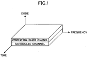
- a conventional W-DCMA as shown in Fig. 1 , multiplexing is performed by CDM (Code Division Multiplex) in which the contention-based channel and the scheduled channel are separated by different spreading codes.
- CDM Code Division Multiplex
- deterioration due to inter-code interference is a problem. This is an unavoidable selection since priority is given to an advantage of using the entire channel band for the contention-based channel and the scheduled channel for obtaining the frequency diversity effect under a constraint that the channel band is 5MHz.
- the present invention is proposed in view of the above-mentioned points, and the object is to provide a radio resource assignment method for a physical channel in an uplink and a transmitter for mobile apparatuses that can properly perform radio resource assignment for a physical channel in an uplink directed to a mobile apparatus to a base station in a mobile radio communication system under an environment of the next generation mobile radio communication system.
- a mobile station having the features of claim 1, a transmission method having the features of claim 3, and a mobile radio communication system having the features of claim 5.
- radio resource assignment method for the physical channel in the uplink and the transmitter for mobile apparatus use of the present invention, code separation is not adopted for dividing between the contention-based channel and the scheduled channel, frequency diversity and multiuser diversity are effectively applied, the power ramping technique is not adopted, assignment of radio resources according to data rates and the like is performed.
- radio resource assignment for physical channel in the uplink directed from a mobile apparatus to a base station in a mobile radio communication system can be properly performed under an environment of a next generation mobile radio communication system.
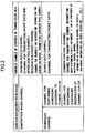
- Fig.2 is a diagram showing examples of physical channels in the uplink.
- the physical channel in the uplink can be largely classified to the contention-based channel and the scheduled channel.
- the contention-based channel includes a random access channel that is a channel used when sending short data or an upper control signal, a reservation packet channel that is a channel for sending reservation information for scheduling before transmitting the scheduled data channel, or the like.
- the scheduled channel is classified to a channel for which scheduling is performed according to channel status and a channel for which scheduling is performed irrespective of channel status.
- the channel for which scheduling is performed according to channel status includes a shared data channel that is a channel for transmitting packet data.
- the channel for which scheduling is performed irrespective of channel status includes a common control channel that is a channel for transmitting control information. But, when fixed assignment is performed, the common control channel may be considered to be an individual control channel.
- Fig.3 is a diagram showing examples of methods for multiplexing the contention-based channel and the scheduled channel.
- Fig.3(a) shows a case for multiplexing a contention-based channel Ch1 and a scheduled channel Ch2 by assigning radio resources in a time division multiplexing (TDM) scheme.
- Fig.3(b) shows a case for multiplexing a contention-based channel Ch1 and a scheduled channel Ch2 by assigning radio resources in a frequency division multiplexing (FDM) scheme.
- Fig.3(c) shows a case for multiplexing a contention-based channel Ch1 and a scheduled channel Ch2 by assigning radio resources in a hybrid scheme of the time division multiplexing scheme and the frequency division multiplexing scheme.
- the present invention is not limited to any one of a single carrier scheme such as DS-CDMA (Direct Sequence Code Division Multiple Access), IFDMA (Interleaved Frequency Division Multiple Access), VSCRF-CDMA (Variable Spreading and Chip Repetition Factors - Code Division Multiple Access), etc. and a multi-carrier scheme such as OFDM (Orthogonal Frequency Division Multiplexing), Spread OFDM, MC-CDMA (Multi-Carrier Code Division Multiple Access) and VSF-Spread OFDM (Variable Spreading Factor - Spread Orthogonal Frequency Division Multiplexing), etc., but the present invention can be applied to both of the schemes.
- a single carrier scheme such as DS-CDMA (Direct Sequence Code Division Multiple Access), IFDMA (Interleaved Frequency Division Multiple Access), VSCRF-CDMA (Variable Spreading and Chip Repetition Factors - Code Division Multiple Access), etc.
- a multi-carrier scheme such as OFDM (Orthogonal Fre
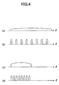
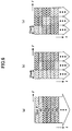
- Fig.4 is a diagram showing examples of radio resource assignment methods for the contention-based channel.
- Figs.4(a) and (b) show cases of assigning an entire channel band to the contention-based channel.
- a continuous spectrum is formed in the assigned frequency band
- a comb-shaped spectrum is formed in the assigned frequency band.
- contention is performed by CDMA and the like
- contention is performed FDMA and CDMA and the like by shifting a position of the comb teeth on the frequency domain.
- Figs.4(c) and (d) show cases where a frequency block formed by one or more chunks is assigned to the contention-based channel.
- Fig.4(c) shows a case forming a continuous spectrum on the assigned frequency band
- Fig.4(d) shows a case forming a comb-shaped spectrum on the assigned frequency band.
- contention is performed by CDMA and the like
- contention is performed by FDMA and CDMA and the like.
- the signal by the contention-based channel is a prerequisite for transmission, after the signal, of packet data by the scheduled channel based on scheduling in the base station side, the signal needs to have few errors due to interference and needs to be effectively transmitted to the base station side within a short period.
- the signal since the signal is distributed over the entire channel band, large frequency diversity effect can be obtained and variation of received signals decreases so that stable communication becomes available. Therefore, it becomes possible to decrease transmission power density, adoption of the power ramping technique that is conventionally performed can be eliminated or decreased, so that occurrence of delay due to the power ramping technique can be avoided.
- interference can be decreased by FDM by forming the comb-shaped spectrum and shifting frequencies from other users (mobile apparatuses).
- Figs.4(a) and (b) are advantageous when a data rate of transmission data is large, and Figs.4(c) and (d) are advantageous when a data rate of the transmission data is small. That is, when the data rate of transmission data is small, transmission power density becomes small according to the cases of Figs.4(a) and (b) so that there is a problem in that channel estimation accuracy when receiving deteriorates. But, in such a case, deterioration of channel estimation accuracy can be prevented by narrowing frequency band so as not to use unnecessary large bandwidth as shown in Figs.4(c) and (d) .
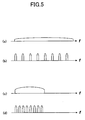
- Fig.5 is a diagram showing an example of a radio resource assignment method for a common control channel of scheduled channels. As shown in the diagram, radio resource assignment similar to that of the before mentioned case of the contention-based channel shown in Fig.4 is performed. That is, the common control channel is essential for adaptive control and ARQ (Automatic Repeat reQuest) according to channel status, low block error rate (BLER) is required, and ARQ cannot be applied to the common control channel itself. Thus, stability by the frequency diversity effect is valued.
- ARQ Automatic Repeat reQuest
- Figs.5(a) and (b) can be adopted when a low block error rate is required, and Figs.5(c) and (d) can be adopted when a required block error rate is not so low.
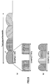
- Fig.6 is a diagram showing examples of radio resource assignment methods for a shared data channel of scheduled channels.
- Fig.6(a) shows a case where the entire channel band is assigned to the shared data channel of scheduled channels to perform scheduling for users #1, #2, #3 .... in a time domain. In this case, although maximum frequency diversity effect can be obtained, multiuser diversity effect is small. By the way, a pilot transmitted by an uplink for CQI measurement is for the entire channel band.
- Fig.6(b) shows a case for performing scheduling in the time domain by fixing a chunk in the frequency domain for the shared data channel of scheduled channels (including a case where equal to or more than two chunks are fixedly assigned to a user of large data).
- the multiuser diversity effect is obtained only in the time domain.
- a frequency band of the chunk large sized one is required in order to be able to accommodate the user of large data.
- a band such as 1.25MHz, 5MHz, 10MHz, and 20MHz can be supposed.
- the pilot transmitted by the uplink for CQI measurement becomes one for a band assigned beforehand.
- Fig.6(c) shows a case for performing scheduling using chunks of the frequency domain and the time domain for the shared data channel of scheduled channels.
- large multiuser diversity effect can be obtained for both of the frequency domain and the time domain.
- a frequency band of the chunk a small sized one is required for obtaining the multiuser diversity effect.
- a band such as 0.3125MHz, 0.625MHz, 1.25MHz, 2.5MHz, 5MHz, 10MHz, and 20MHz can be supposed.
- a pilot transmitted by the uplink for CQI measurement becomes one for the entire channel band since it is unknown which frequency band is assigned in the scheduling.
- Fig.7 is a diagram showing an example of assignment in a case, shown in Fig.6(b) , in which the frequency domain chunk is fixed and scheduling is performed in the time domain.
- Fig.7(a) shows a status in which users are scheduled be assigned to the chunks C1-C4 in the frequency direction respectively.
- Fig.7(b) shows a status in which adjacent chunks C1 and C2 are scheduled to be assigned to a same user, and shows a status in which a center frequency of a radio parameter is shifted to a center of the two chunks C1 and C2 to double the bandwidth so that the two chunks operate in the same way as one chunk.
- Fig.7(c) shows a status in which separated chunks C1 and C3 are scheduled to be assigned to a same user.
- Fig.8 is a diagram showing an example of converting a chunk to sub-chunks when performing scheduling in the time domain by fixing the chunk of the frequency domain as shown in Fig.6(b) . That is, since a band of the chunk (the figure shows 5MHz as an example) cannot be used effectively by assigning a user in units of a chunk when the data rate is low, a plurality of users are multiplexed into a chunk.
- Fig.8(a) shows an example in which multiplexing is performed by dividing an individual chunk C into frequencies using the comb-shaped spectrum. In this case, when a band corresponding to a tooth of the comb becomes too small, it becomes more likely to be affected by phase noise. Thus, it is necessary to pay attention to the smallest size.
- Fig.8(b) shows an example in which multiplexing is performed by normal frequency division. By the way, instead of the comb-shaped spectrum or the normal frequency division, multiplexing may be performed using time division or code division.
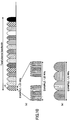
- Fig.9 shows a diagram showing examples of assignment when performing scheduling in the frequency domain and the time domain.
- Fig.9(a) shows a status in which different users are scheduled to be assigned to chunks C1-C16 respectively in the frequency direction.
- Fig.9(b) shows a status in which a same user is scheduled to be assigned to consecutive chunks C1-C8.
- a center frequency of the radio parameter is shifted to a center of the chunks C1-C8 and an eight times bandwidth is used such that it operates in the same way as operation of one chunk. Of course, it is possible to cause it to operate as eight chunks.
- Fig.9(c) shows a state in which separated chunks C1, C3, C4, C7, C10, C12, C15 and C16 are scheduled to be assigned to a same user.
- Fig.10 is a diagram showing examples of converting a chunk to sub-chunks when performing scheduling in the frequency domain and the time domain as shown in Fig.6(c) .
- a band of the chunk (the figure shows 1.25MHz as an example) cannot be used effectively by assigning users in units of a chunk when the data rate is low, a plurality of users are multiplexed into a chunk.
- Fig.10(a) shows an example in which multiplexing is performed by dividing an individual chunk C into frequencies using the comb-shaped spectrum. In this case, when a band corresponding to a tooth of the comb becomes too small, it becomes more likely to be affected by phase noise. Thus, it is necessary to pay attention to a smallest size.
- Fig.10(b) shows an example in which multiplexing is performed by normal frequency division. By the way, instead of the comb-shaped spectrum or normal frequency division, multiplexing may be performed using time division or code division.
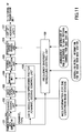
- Fig.11 is a diagram showing a configuration example of a transmitter for mobile apparatuses based on time domain processing corresponding to a single carrier scheme.
- the transmitter for mobile apparatuses includes a transmission data generation unit 101 for generating transmission data, a channel coding unit 102 for performing channel coding on transmission data, a data modulation unit 103 for modulating the channel coded transmission data, and a spreading unit 104 for performing spreading on the modulated transmission data.
- the transmitter includes a symbol repetition unit 105 for repeating symbols (chips) of the spread transmission data, a frequency offset adding unit 106 for providing a frequency offset of each user to transmission data in which symbols are repeated, and a CP/ZP adding unit 107 for adding CP (Cyclic Prefix) or ZP (Zero Padding) as a guard interval to the transmission data to which the frequency offset is added.
- An output signal of the CP/ZP adding unit 107 is provided to a RF (Radio Frequency) transmission unit via filtering not shown in the diagram, and is transmitted.
- RF Radio Frequency
- the transmitter includes, as control units, a data modulation/spreading factor/channel coding control unit 108 for controlling the channel coding unit 102, the data modulation unit 103 and the spreading unit 104 according to a channel type of the transmission data and MCS (Modulation and Coding Scheme) information for the user provided from the base station, and a frequency diversity/scheduling control unit 109 for controlling the symbol repetition unit 105 and the frequency offset adding unit 106 according to the channel type of the transmission data, announcement information, provided from the base station, of radio resource assignment to each physical channel, and scheduling result information for the user.
- MCS Modulation and Coding Scheme
- the transmitter In the operation, the transmitter generates a transmission signal by performing radio resource assignment according to the multiplexing method shown in Fig.3 , and further, generates a transmission signal by assigning radio resources for each channel as shown in Figs.4-6 under control of the data modulation/spreading factor/channel coding control unit 108 and the frequency diversity/scheduling control unit 109 according to a channel type of transmission data, that is, according to whether it is the contention-based channel or the scheduled channel, in addition, according to whether it is the common control channel or the shared data channel when the type is the scheduled channel.
- a channel type of transmission data that is, according to whether it is the contention-based channel or the scheduled channel, in addition, according to whether it is the common control channel or the shared data channel when the type is the scheduled channel.
- the symbol repetition unit 105 compresses chips that are output signals from the spreading unit 104 into each block every Q chips, and repeats it CRF (Chip Repetition Factor) times.
- CRF Chip Repetition Factor
- the continuous spectrum shown in Figs.4(a)(c) and Figs.5(a)(c) is formed.
- CRF>1 the comb-shaped spectrum shown in Figs.4(b)(d) and Figs.5(b)(d) is formed.
- Fig.12 shows a configuration example of a transmitter for mobile apparatuses using frequency domain processing supporting the single carrier scheme. Although comb-shaped spectrum is formed by time domain processing in Fig.11 , same processing can be performed by frequency domain processing in this configuration of Fig.12 .
- the configuration of the transmitter for mobile apparatuses is different from one shown in Fig.11 , in that, instead of the symbol repeating unit 105 and the frequency offset adding unit 106 in Fig.11 , the transmitter is provided with a Q point FFT unit 110 for converting the spread transmission data into a signal in the frequency domain, a frequency domain signal generation unit 111 for mapping the transmission data that has been converted into the frequency domain to the frequency domain, and a Nsub point IFFT unit 112 for converting the transmission data mapped to the frequency domain into signals of the time domain, and that the frequency domain signal generation unit 111 is controlled by the frequency diversity/scheduling control unit 109, and other configuration is the same.
- a Q point FFT unit 110 for converting the spread transmission data into a signal in the frequency domain
- a frequency domain signal generation unit 111 for mapping the transmission data that has been converted into the frequency domain to the frequency domain
- a Nsub point IFFT unit 112 for converting the transmission data mapped to the frequency domain into signals of the time domain
- the Q point FFT unit 110 converts the spread transmission data into Q signals of the frequency domain.
- the Nsub point IFFT unit 112 performs inverse Fourier transform from the frequency domain signals of the number of sub-carriers Nsub to convert the signals into time domain signals.
- Fig.13 is a diagram showing a configuration example of a transmitter for mobile apparatuses supporting a multi-carrier scheme.
- the configuration of the transmitter for mobile apparatuses is different from that of Fig.12 in that, instead of the Q point FFT unit 111 and the frequency domain signal generation unit 111 of Fig.12 , the transmitter is provided with a S/P conversion unit 113 for converting spread transmission data (serial signal) into parallel signals and a frequency domain signal generation unit 114 for mapping the transmission data converted into the parallel signals into the frequency domain, and that the frequency domain signal generation unit 114 is controlled by the frequency diversity/scheduling control unit 109.
- Other configuration is the same.
- the S/P conversion unit of Fig.13 converts the spread transmission data to Nsub signals and passes them to the frequency domain signal generation unit 114.
- mapping to sub-carriers in the frequency domain signal generation unit 114 when the transmission signal of the user is continuously mapped, the continuous spectrum shown in Figs.4(a)(c) and Figs.5(a)(c) is formed.
- the transmission data is mapped at predetermined intervals, the comb-shaped spectrum is formed as shown in Figs.4(b)(d) and Figs.5(b)(d) .
- Fig.14 is a diagram showing an configuration example of a transmitter for mobile apparatuses supporting the both schemes of the single carrier scheme and the multi-carrier scheme.
- This configuration is a hybrid of the configuration of the signal carrier scheme shown in Fig.12 and the configuration of the multi-carrier scheme shown in Fig.13 , and it is provided with a switch unit 115, after the spreading unit 104, for selecting and branching the spread transmission data to the Q point FFT unit 110 and the S/P conversion unit 113.
- the operation is the same as that of the single carrier scheme shown in Fig.12 in a state when the switch unit 115 selects the Q point FFT unit 110 side, and the operation is the same as that of the multi-carrier scheme shown in Fig.13 in a state when the switch unit 115 selects the S/P conversion unit 113 side.
Landscapes
- Engineering & Computer Science (AREA)
- Signal Processing (AREA)
- Computer Networks & Wireless Communication (AREA)
- Quality & Reliability (AREA)
- Mobile Radio Communication Systems (AREA)
- Digital Transmission Methods That Use Modulated Carrier Waves (AREA)
- Time-Division Multiplex Systems (AREA)
Claims (5)
- Station mobile configurée pour transmettre un canal physique en liaison montante dans un système de radiocommunication, comprenant :une unité de commande de planification (109) configurée pour affecter un canal de commande partagé à une bande de canal dans laquelle une pluralité de blocs de fréquences sont agencés selon une direction de fréquence et pour affecter un canal de données partagé à au moins un bloc de fréquences d'une bande de canal ; etune unité de transmission configurée pour transmettre le canal de commande partagé et le canal de données partagé qui sont affectés dans l'unité de commande de planification (109),dans laquelle l'unité de commande de planification (109) est configurée pour réaliser une affectation pour le canal de commande partagé de sorte à former un spectre en forme de peigne,
caractérisée en ce que l'unité de commande de planification est configurée pour réaliser une affectation pour le canal de données partagé de sorte à former un spectre continu, dans laquelle l'unité de commande de planification (109) utilise des blocs de fréquences continus lors de l'affectation du canal de données partagé à un nombre égal ou supérieur à deux blocs de fréquences. - Station mobile selon la revendication 1, dans lequel l'unité de commande de planification (109) affecte le canal de commande partagé dans toute la bande de canal.
- Procédé de transmission destiné à transmettre un canal physique en liaison montante dans un système de radiocommunication, comprenant les étapes consistant àaffecter par une station mobile un canal de commande partagé à une bande de canal dans laquelle une pluralité de blocs de fréquences sont agencés dans une direction de fréquence et affecter par la station mobile un canal de données partagé à au moins un bloc de fréquences d'une bande de canal ; ettransmettre par la station mobile le canal de commande partagé et le canal de données partagé qui sont affectés,dans lequel l'étape d'affectation réalise une affectation pour le canal de commande partagé de sorte à former un spectre en forme de peigne,
caractérisé en ce que l'étape d'affectation réalise une affectation pour le canal de données partagé de sorte à former un spectre continu,
dans lequel l'étape d'affectation utilise des blocs de fréquences continus lors de l'affectation du canal de données partagé à un nombre égal ou supérieur à deux blocs de fréquences. - Procédé de transmission selon la revendication 3, dans lequel l'étape d'affectation affecte le canal de commande partagé dans toute la bande de canal.
- Système de radiocommunication mobile comprenant :une station mobile configurée pour affecter un canal de commande partagé à une bande de canal dans laquelle une pluralité de blocs de fréquences sont agencés dans une direction de fréquence, affecter un canal de données partagé à au moins un bloc de fréquences d'une bande de canal et transmettre le canal de commande partagé et le canal de données partagé qui sont affectés ; etune station de base configurée pour recevoir le canal de données partagé et le canal de commande partagé en provenance de la station mobile,dans lequel la station mobile est configurée pour réaliser une affectation pour le canal de commande partagé de sorte à former un spectre en forme de peigne,
caractérisé en ce que la station mobile est configurée pour réaliser une affectation pour le canal de données partagé de sorte à former un spectre continu,
dans lequel la station mobile utilise des blocs de fréquences continus lors de l'affectation du canal de données partagé à un nombre égal ou supérieur à deux blocs de fréquences.
Priority Applications (1)
| Application Number | Priority Date | Filing Date | Title |
|---|---|---|---|
| EP14193636.9A EP2858278A1 (fr) | 2005-03-31 | 2006-03-27 | Procédé d'attribution de ressources radio de canaux physiques dans une liaison montante et émetteur pour appareils mobiles |
Applications Claiming Priority (2)
| Application Number | Priority Date | Filing Date | Title |
|---|---|---|---|
| JP2005105498A JP4515312B2 (ja) | 2005-03-31 | 2005-03-31 | 移動局、送信方法および移動無線通信システム |
| PCT/JP2006/306112 WO2006106616A1 (fr) | 2005-03-31 | 2006-03-27 | Procede pour affecter des ressources radio de canaux physiques dans une liaison montante et recepteur pour unite mobile |
Related Child Applications (2)
| Application Number | Title | Priority Date | Filing Date |
|---|---|---|---|
| EP14193636.9A Division EP2858278A1 (fr) | 2005-03-31 | 2006-03-27 | Procédé d'attribution de ressources radio de canaux physiques dans une liaison montante et émetteur pour appareils mobiles |
| EP14193636.9A Division-Into EP2858278A1 (fr) | 2005-03-31 | 2006-03-27 | Procédé d'attribution de ressources radio de canaux physiques dans une liaison montante et émetteur pour appareils mobiles |
Publications (3)
| Publication Number | Publication Date |
|---|---|
| EP1865738A1 EP1865738A1 (fr) | 2007-12-12 |
| EP1865738A4 EP1865738A4 (fr) | 2011-05-18 |
| EP1865738B1 true EP1865738B1 (fr) | 2016-06-08 |
Family
ID=37073182
Family Applications (2)
| Application Number | Title | Priority Date | Filing Date |
|---|---|---|---|
| EP06730060.8A Active EP1865738B1 (fr) | 2005-03-31 | 2006-03-27 | Procédé pour affecter des ressources radio de canaux physiques dans une liaison montante et émetteur pour appareils mobiles |
| EP14193636.9A Withdrawn EP2858278A1 (fr) | 2005-03-31 | 2006-03-27 | Procédé d'attribution de ressources radio de canaux physiques dans une liaison montante et émetteur pour appareils mobiles |
Family Applications After (1)
| Application Number | Title | Priority Date | Filing Date |
|---|---|---|---|
| EP14193636.9A Withdrawn EP2858278A1 (fr) | 2005-03-31 | 2006-03-27 | Procédé d'attribution de ressources radio de canaux physiques dans une liaison montante et émetteur pour appareils mobiles |
Country Status (12)
| Country | Link |
|---|---|
| US (1) | US8971283B2 (fr) |
| EP (2) | EP1865738B1 (fr) |
| JP (1) | JP4515312B2 (fr) |
| KR (1) | KR101036258B1 (fr) |
| CN (3) | CN101986759A (fr) |
| AU (1) | AU2006231176B2 (fr) |
| BR (1) | BRPI0609590A2 (fr) |
| HU (1) | HUE029100T2 (fr) |
| PT (1) | PT1865738T (fr) |
| RU (1) | RU2421944C2 (fr) |
| TW (2) | TWI408985B (fr) |
| WO (1) | WO2006106616A1 (fr) |
Cited By (1)
| Publication number | Priority date | Publication date | Assignee | Title |
|---|---|---|---|---|
| KR101768510B1 (ko) | 2013-05-06 | 2017-08-17 | 후아웨이 테크놀러지 컴퍼니 리미티드 | 트래픽 인지 매체 액세스 선택을 위한 시스템 및 방법 |
Families Citing this family (37)
| Publication number | Priority date | Publication date | Assignee | Title |
|---|---|---|---|---|
| US7388923B2 (en) * | 2005-06-07 | 2008-06-17 | Motorola, Inc. | Method and system for adaptive control of sub-carriers |
| JP4675167B2 (ja) * | 2005-06-14 | 2011-04-20 | 株式会社エヌ・ティ・ティ・ドコモ | チャネル割り当て方法、無線通信システム、基地局装置、ユーザ端末 |
| US7961800B2 (en) * | 2005-09-07 | 2011-06-14 | Nec Corporation | Adaptive radio/modulation apparatus, receiver apparatus, wireless communication system, and wireless communication method |
| WO2007069315A1 (fr) * | 2005-12-14 | 2007-06-21 | Mitsubishi Denki Kabushiki Kaisha | Procede d’ordonnancement, station de base et terminal |
| ATE492138T1 (de) * | 2006-07-24 | 2011-01-15 | Koninkl Philips Electronics Nv | Mac-protokoll für zentral gesteuerte mehrkanal- funk-lans |
| PT2078402E (pt) * | 2006-11-01 | 2012-03-30 | Qualcomm Inc | Utilização conjunta de esquemas de multiplexagem de portadora múltipla ou portadora única para comunicações sem fios |
| JPWO2008056774A1 (ja) * | 2006-11-10 | 2010-02-25 | パナソニック株式会社 | 無線通信移動局装置およびmcs選択方法 |
| US8036151B2 (en) * | 2006-12-17 | 2011-10-11 | Qualcomm Incorporated | Power-based rate signaling for cellular uplink |
| EP2418798A3 (fr) * | 2006-12-28 | 2015-06-03 | Sharp Kabushiki Kaisha | Station de base, dispositif de transmission radio, système de communication radio et procédé de communication |
| JP2008211752A (ja) * | 2007-01-31 | 2008-09-11 | Toshiba Corp | 無線通信システム |
| GB2446197A (en) | 2007-02-05 | 2008-08-06 | Nec Corp | Frequency-hopping method and mobile communication system |
| US8345620B2 (en) * | 2007-02-08 | 2013-01-01 | Qualcomm Incorporated | Method and apparatus for frequency hopping with frequency fraction reuse |
| US8218526B2 (en) * | 2007-04-30 | 2012-07-10 | Texas Instruments Incorporated | Uplink synchronization maintenance principles in wireless networks |
| EP2169866A4 (fr) * | 2007-07-09 | 2014-07-09 | Sharp Kk | Procédé de planification et dispositif de station de commande |
| JP5249227B2 (ja) | 2007-08-13 | 2013-07-31 | シャープ株式会社 | 基地局装置および無線通信方法 |
| JP4558020B2 (ja) * | 2007-08-14 | 2010-10-06 | 株式会社エヌ・ティ・ティ・ドコモ | ユーザ装置、送信方法及び通信システム |
| TWI458284B (zh) * | 2007-12-07 | 2014-10-21 | Koninkl Philips Electronics Nv | 分散無線系統中的多頻道支援 |
| US20090180459A1 (en) * | 2008-01-16 | 2009-07-16 | Orlik Philip V | OFDMA Frame Structures for Uplinks in MIMO Networks |
| JP5481371B2 (ja) | 2008-03-05 | 2014-04-23 | シャープ株式会社 | 通信装置および制御方法 |
| WO2009142025A1 (fr) * | 2008-05-23 | 2009-11-26 | パナソニック株式会社 | Dispositif de station mobile de communication sans fil et procédé de distribution et de placement pour des éléments de ressource |
| CA2724744C (fr) | 2008-06-11 | 2014-02-04 | Nokia Siemens Networks Oy | Canal de commande de liaison montante optimisee dans un reseau local |
| KR101500754B1 (ko) * | 2008-08-04 | 2015-03-10 | 엘지전자 주식회사 | 다중 rf 시스템에서 데이터 전송 방법 |
| US8953535B2 (en) * | 2009-12-01 | 2015-02-10 | Lg Electronics Inc. | Method and apparatus for transceiving data via a contention-based physical uplink data channel |
| CN102685731B (zh) * | 2011-03-10 | 2016-09-14 | 中兴通讯股份有限公司 | 一种配置物理信道标识的方法及系统及接入终端的方法 |
| US20140133433A1 (en) * | 2011-07-15 | 2014-05-15 | Lg Electronics Inc. | Communication method and wireless device supporting variable bandwidth |
| WO2015089742A1 (fr) * | 2013-12-17 | 2015-06-25 | 华为技术有限公司 | Procédé de planification, point d'accès, serveur de planification et système de planification |
| CN103813273B (zh) * | 2013-12-23 | 2017-04-12 | 杭州承联通信技术有限公司 | Pdt数字集群基站无线链路信道频率配置及接入的方法 |
| US9762324B2 (en) * | 2014-10-31 | 2017-09-12 | Futurewei Technologies, Inc. | Channel mapping for an aggregated touchless wireless fronthaul |
| US10541791B2 (en) * | 2014-11-25 | 2020-01-21 | Qualcomm Incorporated | Techniques for reducing latency in a wireless communication system |
| US10135562B2 (en) | 2015-05-28 | 2018-11-20 | Huawei Technologies Co., Ltd. | Apparatus and method for link adaptation in uplink grant-less random access |
| EP3326416B1 (fr) * | 2015-07-22 | 2020-01-15 | Telefonaktiebolaget LM Ericsson (publ) | Procédé et noeud de communication pour programmer des ressources radioélectriques |
| EP3355540B1 (fr) * | 2015-10-30 | 2023-05-03 | Huawei Technologies Co., Ltd. | Procédé, dispositif et système de transmission de signaux |
| CN109565881B (zh) * | 2016-08-11 | 2022-09-09 | 诺基亚技术有限公司 | 用于通过有效传输切换策略来实施基于竞争的上行链路传输的方法和装置 |
| CN106936556B (zh) * | 2017-03-07 | 2020-02-14 | 西北工业大学 | 一种面向窄带物联网的时频二维稀疏码多址接入方法 |
| CN106912111A (zh) * | 2017-04-01 | 2017-06-30 | 西北工业大学 | 一种基于调度与竞争细粒度融合的非正交多址接入方法 |
| WO2020145182A1 (fr) * | 2019-01-09 | 2020-07-16 | ソニー株式会社 | Dispositif de communication et procédé de communication |
| WO2020172855A1 (fr) * | 2019-02-28 | 2020-09-03 | 华为技术有限公司 | Procédé d'attribution de temps et dispositif d'attribution de temps |
Family Cites Families (30)
| Publication number | Priority date | Publication date | Assignee | Title |
|---|---|---|---|---|
| JPH0918441A (ja) | 1995-07-03 | 1997-01-17 | Hitachi Ltd | 周波数/時分割多重伝送方法及び方式 |
| US5796726A (en) | 1996-04-08 | 1998-08-18 | Ericsson Inc. | Systems and methods for random access in time division multiple access satellite radiotelephone communications |
| JPH10209956A (ja) * | 1997-01-28 | 1998-08-07 | Nippon Telegr & Teleph Corp <Ntt> | 無線パケット通信方法 |
| JP3127867B2 (ja) * | 1997-11-28 | 2001-01-29 | 日本電気株式会社 | 移動通信システムにおけるランダムアクセス制御方法 |
| JP2920131B1 (ja) * | 1998-01-28 | 1999-07-19 | 株式会社次世代デジタルテレビジョン放送システム研究所 | Ofdm信号送出装置 |
| JP3301724B2 (ja) | 1998-03-13 | 2002-07-15 | 直樹 末広 | 相補系列繰返し変調形櫛の歯状スペクトル通信方式 |
| KR100290862B1 (ko) * | 1998-04-02 | 2001-07-12 | 구자홍 | 이동통신시스템에서의패킷데이터를전송하기위한슬롯의구조 |
| GB9900389D0 (en) * | 1999-01-09 | 1999-02-24 | Philips Electronics Nv | Radio communication system |
| EP1033849A1 (fr) | 1999-03-01 | 2000-09-06 | Alcatel | Procédé contrôlant l'accès à la ressource radio pour la transmission de paquets d'uplink dans un réseau de transmission sans fil |
| DE19940753C2 (de) | 1999-08-27 | 2001-09-06 | Siemens Ag | Verfahren zum Zuweisen von Übertragungsressourcen der Aufwärtsrichtung einer Funkübertragung |
| US6631124B1 (en) * | 1999-11-03 | 2003-10-07 | Ericsson Inc. | Methods and apparatus for allocating resources in hybrid TDMA communication systems |
| JP3522619B2 (ja) | 2000-01-05 | 2004-04-26 | 株式会社エヌ・ティ・ティ・ドコモ | マルチキャリアcdma伝送システムにおける送信機 |
| JP3581072B2 (ja) | 2000-01-24 | 2004-10-27 | 株式会社エヌ・ティ・ティ・ドコモ | チャネル構成方法及びその方法を利用する基地局 |
| DE60016373T2 (de) | 2000-02-15 | 2005-12-01 | Lucent Technologies Inc. | Verfahren und Mobilfunksystem mit verbesserten Ressourcenzuweisung für die Aufwärtsrichtung |
| US20020114311A1 (en) * | 2001-02-16 | 2002-08-22 | Sara Mazur | Continuous allocation of real-time traffic in a telecommunication system |
| US7088734B2 (en) * | 2001-03-27 | 2006-08-08 | Motorola, Inc. | Slot format and method for increasing random access opportunities in a wireless communication system |
| US6836666B2 (en) * | 2001-05-08 | 2004-12-28 | Lucent Technologies Inc. | Method to control uplink transmissions in a wireless communication system |
| EP1890392B1 (fr) * | 2001-09-18 | 2015-08-12 | Electronics and Telecommunications Research Institute | Procédé et système de communication numérique |
| JP2003101499A (ja) | 2001-09-25 | 2003-04-04 | Victor Co Of Japan Ltd | マルチキャリア信号の生成方法、マルチキャリア信号の復号方法、マルチキャリア信号生成装置、及びマルチキャリア信号復号装置 |
| US7248559B2 (en) * | 2001-10-17 | 2007-07-24 | Nortel Networks Limited | Scattered pilot pattern and channel estimation method for MIMO-OFDM systems |
| KR100564686B1 (ko) | 2001-11-08 | 2006-03-30 | 가부시키가이샤 엔티티 도코모 | 프리앰블 송신 방법, 이동국, 이동 통신 시스템, 프리앰블송신 프로그램 및 컴퓨터 데이터 신호 |
| JP2003264873A (ja) | 2002-03-08 | 2003-09-19 | Matsushita Electric Ind Co Ltd | 無線通信装置及び再送方法 |
| JP2003309533A (ja) | 2002-04-17 | 2003-10-31 | Matsushita Electric Ind Co Ltd | 無線送信装置、無線受信装置及びその方法 |
| JP4256207B2 (ja) | 2002-06-28 | 2009-04-22 | パナソニック株式会社 | 送信装置および通信モード選択用テーブル更新方法 |
| JP4318510B2 (ja) * | 2002-08-28 | 2009-08-26 | パナソニック株式会社 | 通信装置および通信方法 |
| US6928062B2 (en) * | 2002-10-29 | 2005-08-09 | Qualcomm, Incorporated | Uplink pilot and signaling transmission in wireless communication systems |
| GB0225903D0 (en) * | 2002-11-07 | 2002-12-11 | Siemens Ag | Method for uplink access transmissions in a radio communication system |
| JP4276009B2 (ja) * | 2003-02-06 | 2009-06-10 | 株式会社エヌ・ティ・ティ・ドコモ | 移動局、基地局、無線伝送プログラム、及び無線伝送方法 |
| US20050054347A1 (en) | 2003-09-05 | 2005-03-10 | Kakani Naveen Kumar | Uplink resource allocation |
| US7894548B2 (en) * | 2004-09-03 | 2011-02-22 | Qualcomm Incorporated | Spatial spreading with space-time and space-frequency transmit diversity schemes for a wireless communication system |
-
2005
- 2005-03-31 JP JP2005105498A patent/JP4515312B2/ja active Active
-
2006
- 2006-03-27 PT PT67300608T patent/PT1865738T/pt unknown
- 2006-03-27 RU RU2007136732/09A patent/RU2421944C2/ru not_active IP Right Cessation
- 2006-03-27 BR BRPI0609590-9A patent/BRPI0609590A2/pt not_active IP Right Cessation
- 2006-03-27 WO PCT/JP2006/306112 patent/WO2006106616A1/fr active Application Filing
- 2006-03-27 EP EP06730060.8A patent/EP1865738B1/fr active Active
- 2006-03-27 CN CN2010105271336A patent/CN101986759A/zh active Pending
- 2006-03-27 US US11/909,704 patent/US8971283B2/en active Active
- 2006-03-27 CN CN2011102067835A patent/CN102348283A/zh active Pending
- 2006-03-27 CN CNA2006800140903A patent/CN101167395A/zh active Pending
- 2006-03-27 HU HUE06730060A patent/HUE029100T2/hu unknown
- 2006-03-27 EP EP14193636.9A patent/EP2858278A1/fr not_active Withdrawn
- 2006-03-27 KR KR1020077023245A patent/KR101036258B1/ko not_active IP Right Cessation
- 2006-03-27 AU AU2006231176A patent/AU2006231176B2/en not_active Ceased
- 2006-03-29 TW TW097100799A patent/TWI408985B/zh not_active IP Right Cessation
- 2006-03-29 TW TW095110957A patent/TWI388134B/zh not_active IP Right Cessation
Non-Patent Citations (2)
| Title |
|---|
| NTT DOCOMO: "Uplink Multiple Access Scheme for Evolved UTRA", 3GPP DRAFT; R1-050248, 3RD GENERATION PARTNERSHIP PROJECT (3GPP), MOBILE COMPETENCE CENTRE ; 650, ROUTE DES LUCIOLES ; F-06921 SOPHIA-ANTIPOLIS CEDEX ; FRANCE, vol. RAN WG1, no. Beijing, china; 20050330, 30 March 2005 (2005-03-30), XP050099911 * |
| SCHNELL M ET AL: "A PROMISING NEW WIDEBAND MULTIPLE-ACCESS SCHEME FOR FUTURE MOBILE COMMUNICATIONS SYSTEMS", EUROPEAN TRANSACTIONS ON TELECOMMUNICATIONS, WILEY & SONS, CHICHESTER, GB, vol. 10, no. 4, 1 July 1999 (1999-07-01), pages 417 - 427, XP009069928, ISSN: 1124-318X * |
Cited By (1)
| Publication number | Priority date | Publication date | Assignee | Title |
|---|---|---|---|---|
| KR101768510B1 (ko) | 2013-05-06 | 2017-08-17 | 후아웨이 테크놀러지 컴퍼니 리미티드 | 트래픽 인지 매체 액세스 선택을 위한 시스템 및 방법 |
Also Published As
| Publication number | Publication date |
|---|---|
| HUE029100T2 (hu) | 2017-02-28 |
| US8971283B2 (en) | 2015-03-03 |
| JP4515312B2 (ja) | 2010-07-28 |
| EP2858278A1 (fr) | 2015-04-08 |
| AU2006231176A1 (en) | 2006-10-12 |
| TW200704244A (en) | 2007-01-16 |
| JP2006287664A (ja) | 2006-10-19 |
| TWI408985B (zh) | 2013-09-11 |
| CN102348283A (zh) | 2012-02-08 |
| US20090103483A1 (en) | 2009-04-23 |
| CN101986759A (zh) | 2011-03-16 |
| EP1865738A4 (fr) | 2011-05-18 |
| EP1865738A1 (fr) | 2007-12-12 |
| WO2006106616A1 (fr) | 2006-10-12 |
| CN101167395A (zh) | 2008-04-23 |
| KR101036258B1 (ko) | 2011-05-23 |
| KR20070118637A (ko) | 2007-12-17 |
| AU2006231176B2 (en) | 2011-01-06 |
| RU2421944C2 (ru) | 2011-06-20 |
| TW200824483A (en) | 2008-06-01 |
| RU2007136732A (ru) | 2009-05-10 |
| PT1865738T (pt) | 2016-09-05 |
| BRPI0609590A2 (pt) | 2010-04-20 |
| TWI388134B (zh) | 2013-03-01 |
Similar Documents
| Publication | Publication Date | Title |
|---|---|---|
| EP1865738B1 (fr) | Procédé pour affecter des ressources radio de canaux physiques dans une liaison montante et émetteur pour appareils mobiles | |
| EP1489775B1 (fr) | Méthode et dispositif de transmission pour utilisateur dans un système de communication mobile fondée sur le multiplexage par division en fréquences orthogonales | |
| KR101017259B1 (ko) | 송신장치, 수신장치, 이동통신 시스템, 및 송신제어방법 | |
| KR101036256B1 (ko) | 유저장치, 기지국장치 및 방법 | |
| US9065596B2 (en) | Wireless communication system and wireless communication method | |
| JP5450389B2 (ja) | パケット・ワイヤレス遠距離通信のための方法および装置 | |
| US8305989B2 (en) | Method for allocating pilots | |
| JP2004135305A (ja) | Ofmdaを使用するhsdpaシステムのためのフィードバック方法 | |
| JP2009543402A (ja) | 帯域幅非対称通信システム | |
| KR20140012195A (ko) | 유저장치, 기지국장치 및 방법 | |
| WO2008094022A1 (fr) | Procédé de transmission de signal de référence de programmation | |
| JP4955041B2 (ja) | 基地局、受信方法、移動局、送信方法 |
Legal Events
| Date | Code | Title | Description |
|---|---|---|---|
| PUAI | Public reference made under article 153(3) epc to a published international application that has entered the european phase |
Free format text: ORIGINAL CODE: 0009012 |
|
| 17P | Request for examination filed |
Effective date: 20070925 |
|
| AK | Designated contracting states |
Kind code of ref document: A1 Designated state(s): AT BE BG CH CY CZ DE DK EE ES FI FR GB GR HU IE IS IT LI LT LU LV MC NL PL PT RO SE SI SK TR |
|
| DAX | Request for extension of the european patent (deleted) | ||
| A4 | Supplementary search report drawn up and despatched |
Effective date: 20110414 |
|
| 17Q | First examination report despatched |
Effective date: 20120628 |
|
| REG | Reference to a national code |
Ref country code: DE Ref legal event code: R079 Ref document number: 602006049286 Country of ref document: DE Free format text: PREVIOUS MAIN CLASS: H04Q0007380000 Ipc: H04J0001000000 |
|
| RIC1 | Information provided on ipc code assigned before grant |
Ipc: H04J 1/00 20060101AFI20151201BHEP Ipc: H04L 5/00 20060101ALI20151201BHEP Ipc: H04J 3/16 20060101ALI20151201BHEP Ipc: H04W 74/02 20090101ALN20151201BHEP Ipc: H04W 72/04 20090101ALN20151201BHEP Ipc: H04L 1/00 20060101ALN20151201BHEP Ipc: H04J 4/00 20060101ALI20151201BHEP |
|
| RIC1 | Information provided on ipc code assigned before grant |
Ipc: H04L 1/00 20060101ALN20151210BHEP Ipc: H04W 74/02 20090101ALN20151210BHEP Ipc: H04L 5/00 20060101ALI20151210BHEP Ipc: H04J 3/16 20060101ALI20151210BHEP Ipc: H04W 72/04 20090101ALN20151210BHEP Ipc: H04J 1/00 20060101AFI20151210BHEP Ipc: H04J 4/00 20060101ALI20151210BHEP |
|
| GRAP | Despatch of communication of intention to grant a patent |
Free format text: ORIGINAL CODE: EPIDOSNIGR1 |
|
| INTG | Intention to grant announced |
Effective date: 20160119 |
|
| GRAS | Grant fee paid |
Free format text: ORIGINAL CODE: EPIDOSNIGR3 |
|
| GRAA | (expected) grant |
Free format text: ORIGINAL CODE: 0009210 |
|
| AK | Designated contracting states |
Kind code of ref document: B1 Designated state(s): AT BE BG CH CY CZ DE DK EE ES FI FR GB GR HU IE IS IT LI LT LU LV MC NL PL PT RO SE SI SK TR |
|
| REG | Reference to a national code |
Ref country code: GB Ref legal event code: FG4D |
|
| REG | Reference to a national code |
Ref country code: CH Ref legal event code: EP |
|
| REG | Reference to a national code |
Ref country code: IE Ref legal event code: FG4D |
|
| REG | Reference to a national code |
Ref country code: AT Ref legal event code: REF Ref document number: 805875 Country of ref document: AT Kind code of ref document: T Effective date: 20160715 |
|
| REG | Reference to a national code |
Ref country code: DE Ref legal event code: R096 Ref document number: 602006049286 Country of ref document: DE |
|
| REG | Reference to a national code |
Ref country code: PT Ref legal event code: SC4A Ref document number: 1865738 Country of ref document: PT Date of ref document: 20160905 Kind code of ref document: T Free format text: AVAILABILITY OF NATIONAL TRANSLATION Effective date: 20160830 |
|
| REG | Reference to a national code |
Ref country code: LT Ref legal event code: MG4D |
|
| REG | Reference to a national code |
Ref country code: NL Ref legal event code: MP Effective date: 20160608 |
|
| PG25 | Lapsed in a contracting state [announced via postgrant information from national office to epo] |
Ref country code: LT Free format text: LAPSE BECAUSE OF FAILURE TO SUBMIT A TRANSLATION OF THE DESCRIPTION OR TO PAY THE FEE WITHIN THE PRESCRIBED TIME-LIMIT Effective date: 20160608 Ref country code: FI Free format text: LAPSE BECAUSE OF FAILURE TO SUBMIT A TRANSLATION OF THE DESCRIPTION OR TO PAY THE FEE WITHIN THE PRESCRIBED TIME-LIMIT Effective date: 20160608 |
|
| REG | Reference to a national code |
Ref country code: AT Ref legal event code: MK05 Ref document number: 805875 Country of ref document: AT Kind code of ref document: T Effective date: 20160608 |
|
| PG25 | Lapsed in a contracting state [announced via postgrant information from national office to epo] |
Ref country code: GR Free format text: LAPSE BECAUSE OF FAILURE TO SUBMIT A TRANSLATION OF THE DESCRIPTION OR TO PAY THE FEE WITHIN THE PRESCRIBED TIME-LIMIT Effective date: 20160909 Ref country code: ES Free format text: LAPSE BECAUSE OF FAILURE TO SUBMIT A TRANSLATION OF THE DESCRIPTION OR TO PAY THE FEE WITHIN THE PRESCRIBED TIME-LIMIT Effective date: 20160608 Ref country code: NL Free format text: LAPSE BECAUSE OF FAILURE TO SUBMIT A TRANSLATION OF THE DESCRIPTION OR TO PAY THE FEE WITHIN THE PRESCRIBED TIME-LIMIT Effective date: 20160608 Ref country code: LV Free format text: LAPSE BECAUSE OF FAILURE TO SUBMIT A TRANSLATION OF THE DESCRIPTION OR TO PAY THE FEE WITHIN THE PRESCRIBED TIME-LIMIT Effective date: 20160608 Ref country code: SE Free format text: LAPSE BECAUSE OF FAILURE TO SUBMIT A TRANSLATION OF THE DESCRIPTION OR TO PAY THE FEE WITHIN THE PRESCRIBED TIME-LIMIT Effective date: 20160608 |
|
| PG25 | Lapsed in a contracting state [announced via postgrant information from national office to epo] |
Ref country code: IT Free format text: LAPSE BECAUSE OF FAILURE TO SUBMIT A TRANSLATION OF THE DESCRIPTION OR TO PAY THE FEE WITHIN THE PRESCRIBED TIME-LIMIT Effective date: 20160608 Ref country code: EE Free format text: LAPSE BECAUSE OF FAILURE TO SUBMIT A TRANSLATION OF THE DESCRIPTION OR TO PAY THE FEE WITHIN THE PRESCRIBED TIME-LIMIT Effective date: 20160608 Ref country code: CZ Free format text: LAPSE BECAUSE OF FAILURE TO SUBMIT A TRANSLATION OF THE DESCRIPTION OR TO PAY THE FEE WITHIN THE PRESCRIBED TIME-LIMIT Effective date: 20160608 Ref country code: SK Free format text: LAPSE BECAUSE OF FAILURE TO SUBMIT A TRANSLATION OF THE DESCRIPTION OR TO PAY THE FEE WITHIN THE PRESCRIBED TIME-LIMIT Effective date: 20160608 Ref country code: RO Free format text: LAPSE BECAUSE OF FAILURE TO SUBMIT A TRANSLATION OF THE DESCRIPTION OR TO PAY THE FEE WITHIN THE PRESCRIBED TIME-LIMIT Effective date: 20160608 Ref country code: IS Free format text: LAPSE BECAUSE OF FAILURE TO SUBMIT A TRANSLATION OF THE DESCRIPTION OR TO PAY THE FEE WITHIN THE PRESCRIBED TIME-LIMIT Effective date: 20161008 |
|
| PG25 | Lapsed in a contracting state [announced via postgrant information from national office to epo] |
Ref country code: PL Free format text: LAPSE BECAUSE OF FAILURE TO SUBMIT A TRANSLATION OF THE DESCRIPTION OR TO PAY THE FEE WITHIN THE PRESCRIBED TIME-LIMIT Effective date: 20160608 Ref country code: BE Free format text: LAPSE BECAUSE OF FAILURE TO SUBMIT A TRANSLATION OF THE DESCRIPTION OR TO PAY THE FEE WITHIN THE PRESCRIBED TIME-LIMIT Effective date: 20160608 Ref country code: AT Free format text: LAPSE BECAUSE OF FAILURE TO SUBMIT A TRANSLATION OF THE DESCRIPTION OR TO PAY THE FEE WITHIN THE PRESCRIBED TIME-LIMIT Effective date: 20160608 |
|
| REG | Reference to a national code |
Ref country code: HU Ref legal event code: AG4A Ref document number: E029100 Country of ref document: HU |
|
| REG | Reference to a national code |
Ref country code: DE Ref legal event code: R097 Ref document number: 602006049286 Country of ref document: DE |
|
| PLBE | No opposition filed within time limit |
Free format text: ORIGINAL CODE: 0009261 |
|
| STAA | Information on the status of an ep patent application or granted ep patent |
Free format text: STATUS: NO OPPOSITION FILED WITHIN TIME LIMIT |
|
| 26N | No opposition filed |
Effective date: 20170309 |
|
| PG25 | Lapsed in a contracting state [announced via postgrant information from national office to epo] |
Ref country code: DK Free format text: LAPSE BECAUSE OF FAILURE TO SUBMIT A TRANSLATION OF THE DESCRIPTION OR TO PAY THE FEE WITHIN THE PRESCRIBED TIME-LIMIT Effective date: 20160608 Ref country code: SI Free format text: LAPSE BECAUSE OF FAILURE TO SUBMIT A TRANSLATION OF THE DESCRIPTION OR TO PAY THE FEE WITHIN THE PRESCRIBED TIME-LIMIT Effective date: 20160608 |
|
| REG | Reference to a national code |
Ref country code: CH Ref legal event code: PL |
|
| PG25 | Lapsed in a contracting state [announced via postgrant information from national office to epo] |
Ref country code: MC Free format text: LAPSE BECAUSE OF FAILURE TO SUBMIT A TRANSLATION OF THE DESCRIPTION OR TO PAY THE FEE WITHIN THE PRESCRIBED TIME-LIMIT Effective date: 20160608 |
|
| REG | Reference to a national code |
Ref country code: IE Ref legal event code: MM4A |
|
| REG | Reference to a national code |
Ref country code: FR Ref legal event code: ST Effective date: 20171130 |
|
| PG25 | Lapsed in a contracting state [announced via postgrant information from national office to epo] |
Ref country code: LU Free format text: LAPSE BECAUSE OF NON-PAYMENT OF DUE FEES Effective date: 20170327 Ref country code: FR Free format text: LAPSE BECAUSE OF NON-PAYMENT OF DUE FEES Effective date: 20170331 |
|
| PG25 | Lapsed in a contracting state [announced via postgrant information from national office to epo] |
Ref country code: CH Free format text: LAPSE BECAUSE OF NON-PAYMENT OF DUE FEES Effective date: 20170331 Ref country code: IE Free format text: LAPSE BECAUSE OF NON-PAYMENT OF DUE FEES Effective date: 20170327 Ref country code: LI Free format text: LAPSE BECAUSE OF NON-PAYMENT OF DUE FEES Effective date: 20170331 |
|
| PG25 | Lapsed in a contracting state [announced via postgrant information from national office to epo] |
Ref country code: BG Free format text: LAPSE BECAUSE OF FAILURE TO SUBMIT A TRANSLATION OF THE DESCRIPTION OR TO PAY THE FEE WITHIN THE PRESCRIBED TIME-LIMIT Effective date: 20160608 |
|
| PG25 | Lapsed in a contracting state [announced via postgrant information from national office to epo] |
Ref country code: CY Free format text: LAPSE BECAUSE OF NON-PAYMENT OF DUE FEES Effective date: 20160608 |
|
| PG25 | Lapsed in a contracting state [announced via postgrant information from national office to epo] |
Ref country code: TR Free format text: LAPSE BECAUSE OF FAILURE TO SUBMIT A TRANSLATION OF THE DESCRIPTION OR TO PAY THE FEE WITHIN THE PRESCRIBED TIME-LIMIT Effective date: 20160608 |
|
| P01 | Opt-out of the competence of the unified patent court (upc) registered |
Effective date: 20230509 |
|
| PGFP | Annual fee paid to national office [announced via postgrant information from national office to epo] |
Ref country code: HU Payment date: 20240322 Year of fee payment: 19 Ref country code: DE Payment date: 20240320 Year of fee payment: 19 Ref country code: PT Payment date: 20240314 Year of fee payment: 19 Ref country code: GB Payment date: 20240320 Year of fee payment: 19 |