EP1865613A2 - UWB kooperatives kohärentes Nachrichtentechniksystem - Google Patents
UWB kooperatives kohärentes Nachrichtentechniksystem Download PDFInfo
- Publication number
- EP1865613A2 EP1865613A2 EP07109489A EP07109489A EP1865613A2 EP 1865613 A2 EP1865613 A2 EP 1865613A2 EP 07109489 A EP07109489 A EP 07109489A EP 07109489 A EP07109489 A EP 07109489A EP 1865613 A2 EP1865613 A2 EP 1865613A2
- Authority
- EP
- European Patent Office
- Prior art keywords
- symbols
- terminals
- terminal
- coefficients
- permutation
- Prior art date
- Legal status (The legal status is an assumption and is not a legal conclusion. Google has not performed a legal analysis and makes no representation as to the accuracy of the status listed.)
- Granted
Links
- 230000001427 coherent effect Effects 0.000 title description 7
- 238000004891 communication Methods 0.000 title description 3
- 230000005540 biological transmission Effects 0.000 claims abstract description 65
- 238000000034 method Methods 0.000 claims abstract description 20
- 239000002131 composite material Substances 0.000 claims abstract description 6
- 230000003595 spectral effect Effects 0.000 claims description 8
- 230000003321 amplification Effects 0.000 claims description 5
- 238000003199 nucleic acid amplification method Methods 0.000 claims description 5
- 230000002123 temporal effect Effects 0.000 claims description 4
- 239000013598 vector Substances 0.000 description 29
- 239000011159 matrix material Substances 0.000 description 10
- 230000014509 gene expression Effects 0.000 description 9
- 238000001514 detection method Methods 0.000 description 4
- 238000012545 processing Methods 0.000 description 3
- 230000006870 function Effects 0.000 description 2
- 208000031968 Cadaver Diseases 0.000 description 1
- 102000005717 Myeloma Proteins Human genes 0.000 description 1
- 108010045503 Myeloma Proteins Proteins 0.000 description 1
- 230000033590 base-excision repair Effects 0.000 description 1
- 230000015556 catabolic process Effects 0.000 description 1
- 230000001413 cellular effect Effects 0.000 description 1
- 238000006731 degradation reaction Methods 0.000 description 1
- 235000021183 entrée Nutrition 0.000 description 1
- 230000000116 mitigating effect Effects 0.000 description 1
- 238000012986 modification Methods 0.000 description 1
- 230000004048 modification Effects 0.000 description 1
- 238000011160 research Methods 0.000 description 1
- 238000010187 selection method Methods 0.000 description 1
- 238000000926 separation method Methods 0.000 description 1
- 230000017105 transposition Effects 0.000 description 1
Images

Classifications
-
- H—ELECTRICITY
- H04—ELECTRIC COMMUNICATION TECHNIQUE
- H04L—TRANSMISSION OF DIGITAL INFORMATION, e.g. TELEGRAPHIC COMMUNICATION
- H04L27/00—Modulated-carrier systems
-
- H—ELECTRICITY
- H04—ELECTRIC COMMUNICATION TECHNIQUE
- H04L—TRANSMISSION OF DIGITAL INFORMATION, e.g. TELEGRAPHIC COMMUNICATION
- H04L1/00—Arrangements for detecting or preventing errors in the information received
- H04L1/02—Arrangements for detecting or preventing errors in the information received by diversity reception
- H04L1/06—Arrangements for detecting or preventing errors in the information received by diversity reception using space diversity
- H04L1/0618—Space-time coding
- H04L1/0625—Transmitter arrangements
-
- H—ELECTRICITY
- H04—ELECTRIC COMMUNICATION TECHNIQUE
- H04B—TRANSMISSION
- H04B1/00—Details of transmission systems, not covered by a single one of groups H04B3/00 - H04B13/00; Details of transmission systems not characterised by the medium used for transmission
- H04B1/69—Spread spectrum techniques
- H04B1/7163—Spread spectrum techniques using impulse radio
- H04B1/7176—Data mapping, e.g. modulation
-
- H—ELECTRICITY
- H04—ELECTRIC COMMUNICATION TECHNIQUE
- H04B—TRANSMISSION
- H04B14/00—Transmission systems not characterised by the medium used for transmission
- H04B14/02—Transmission systems not characterised by the medium used for transmission characterised by the use of pulse modulation
- H04B14/023—Transmission systems not characterised by the medium used for transmission characterised by the use of pulse modulation using pulse amplitude modulation
-
- H—ELECTRICITY
- H04—ELECTRIC COMMUNICATION TECHNIQUE
- H04B—TRANSMISSION
- H04B14/00—Transmission systems not characterised by the medium used for transmission
- H04B14/02—Transmission systems not characterised by the medium used for transmission characterised by the use of pulse modulation
- H04B14/026—Transmission systems not characterised by the medium used for transmission characterised by the use of pulse modulation using pulse time characteristics modulation, e.g. width, position, interval
-
- H—ELECTRICITY
- H04—ELECTRIC COMMUNICATION TECHNIQUE
- H04B—TRANSMISSION
- H04B7/00—Radio transmission systems, i.e. using radiation field
-
- H—ELECTRICITY
- H04—ELECTRIC COMMUNICATION TECHNIQUE
- H04B—TRANSMISSION
- H04B7/00—Radio transmission systems, i.e. using radiation field
- H04B7/14—Relay systems
- H04B7/15—Active relay systems
- H04B7/155—Ground-based stations
- H04B7/15507—Relay station based processing for cell extension or control of coverage area
- H04B7/15514—Relay station based processing for cell extension or control of coverage area for shadowing compensation
-
- H—ELECTRICITY
- H04—ELECTRIC COMMUNICATION TECHNIQUE
- H04L—TRANSMISSION OF DIGITAL INFORMATION, e.g. TELEGRAPHIC COMMUNICATION
- H04L1/00—Arrangements for detecting or preventing errors in the information received
- H04L1/02—Arrangements for detecting or preventing errors in the information received by diversity reception
- H04L1/06—Arrangements for detecting or preventing errors in the information received by diversity reception using space diversity
- H04L1/0618—Space-time coding
- H04L1/0637—Properties of the code
-
- H—ELECTRICITY
- H04—ELECTRIC COMMUNICATION TECHNIQUE
- H04L—TRANSMISSION OF DIGITAL INFORMATION, e.g. TELEGRAPHIC COMMUNICATION
- H04L1/00—Arrangements for detecting or preventing errors in the information received
- H04L2001/0092—Error control systems characterised by the topology of the transmission link
Definitions
- the present invention relates both to the field of ultra-wideband or UWB (Ultra Wide Band) telecommunications and that of cooperative telecommunication systems.
- UWB Ultra Wide Band
- UWB telecommunication systems have been the subject of considerable research in recent years. These systems have the specificity of working directly in baseband on so-called ultra-wide band signals.
- a UWB signal is generally understood to mean a signal conforming to the spectral mask stipulated in the FCC regulation of February 14, 2002, revised in March 2005, that is to say, essentially a signal in the spectral band 3.1 to 10. , 6 GHz and having a bandwidth of at least 500 MHz at -10dB.
- UWB signals are divided into two categories: OFDM multi-band signals (MB-OFDM) and pulse-type UWB signals.
- a pulse UWB signal consists of very short pulses, of the order of a few hundred picoseconds to the nanosecond. Subsequently, we will limit our to UWB pulse systems.
- UWB systems are good candidates for wireless personal networks (WPAN).
- WPAN wireless personal networks
- a network without conventional thread like a cellular telecommunication network
- the links are established between a transmitter and a receiver, without the participation of third-party terminals.
- ad-hoc architectures implementing cooperation strategies between terminals have been proposed.
- Fig. 1 very schematically represents a cooperation strategy within such a network.
- the source terminal transmits a data stream to a destination terminal d.
- the terminal r also receives the data stream from s and relays it to the destination terminal d.
- the terminal r thus cooperates with the transmission of data between s and d .
- the s - d channel is of poor quality, in particular because of the presence of an obstacle between s and d
- the s - r - d channel can make it possible to bypass it and obtain a satisfactory link quality.
- the data stream can be relayed by multiple terminals to further increase the spatial diversity of the transmission paths. In addition, it can be relayed at once (single-hop) or in multiple consecutive times (multiple-hop).
- each terminal has a transmission interval dedicated thereto.
- cooperation There are two types of cooperation: parallel cooperation and serial cooperation.
- the relay terminal receives the data from the source terminal during the transmission interval allocated to it and the retransmits to the destination terminal during its own transmission interval.
- the destination terminal thus receives the same data, via different routing paths, a first time during the transmission interval of the source terminal and a second time during the transmission interval of the relay terminal.
- the qualifier of parallel may seem ill-chosen because of the sequential reception of the data by the destination terminal, it actually means the absence of interference between the two routing paths, resulting from the temporal separation of the transmission slots of the terminal. source terminal and relay terminal. Operation in parallel cooperation mode assumes that the relay terminal does not have data specific to transmit during its transmission interval. This greatly reduces the cooperation configurations.
- the relay terminal receives and retransmits the data of the source terminal during the transmission interval allocated thereto. To do this, it can be content to retransmit, after amplification, the received signal (protocol called AF for Amplify and Forward) or to previously decode the signal before re-issuing (protocol says Decode and Forward).
- the destination terminal receives the data from the source terminal, via different routing paths, during the transmission interval allocated to the source terminal.
- DSTC Distributed Space Time Code
- the objective of the invention is to propose a coherent cooperative system using UWB signals while having a higher coding gain than that of the prior art.
- the present invention is defined by a distributed spatio-temporal encoding method for a UWB pulse telecommunication system in which a source terminal transmits a signal to a destination terminal during a transmission interval consisting of K frames, K ⁇ 1 each frame being divided into a first and a second half-frame, the signal transmitted in each first half-frame being received and then retransmitted after amplification during the next second half-frame by a separate relay terminal among K relay terminals of said system.
- Said source terminal encodes 4K information symbols belonging to a PPM modulation alphabet or a PPM-PAM composite modulation alphabet comprising a plurality of time positions, to provide a sequence of four transmission symbols per frame, said transmission symbols being obtained from 4K linear combinations of said information symbols using a plurality of coefficients belonging to a real algebraic extension of order 2 K of the body of the rationals and, for one of said transmission symbols of rank determined in said sequence of each frame, a permutation of its PPM components.
- the transmission symbols thus obtained modulate a pulse UWB signal.
- the idea underlying the invention is to use a cooperation strategy using UWB signals pulses modulated by a modulation of position and amplitude or PPM-PAM (Pulse Position Modulation & Pulse Amplitude Modulation) and to take care to maintain the orthogonality between the signal to be relayed and the signal relayed by means of a specific type of coding .
- PPM-PAM Pulse Position Modulation & Pulse Amplitude Modulation
- the cooperation strategy used is of type AF as illustrated in FIG. 2.
- a source terminal s K relay terminals r 1 , r 2 ,..., R K with K ⁇ 1, and a destination terminal d.
- the transmission interval noted TTI is allocated to the source terminal s. In other words, during this time window, only the source terminal s can transmit, the relays r 1 , r 2 ,..., R K merely relaying the signal transmitted by the source terminal.
- the signal transmitted by the source terminal in the TTI window consists of a sequence of K frames, each of duration T f and consists of two half-frames. If we consider for example the k th frame of the sequence, its first half-frame is relayed by the relay terminal r k while the source emits its second half-frame. Thus the first half frame of each frame of the sequence is relayed by a different relay terminal.
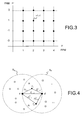
- M ' The alphabet of this cardinal modulation M. M 'has been shown schematically in FIG. 3. For each of the M time positions, M 'modulation amplitudes are possible.
- d is a position of the modulation PPM and has a amplitude of PAM modulation
- ⁇ (.) is the distribution of Dirac.
- the source terminal transmits the symbols vs 2 k , vs 4 k during the first half-frame of the k th frame and then the symbols vs 1 k , vs 3 k during the second half-frame.
- the relay terminal r k receives the symbols vs 2 k , vs 4 k during the first half-frame and retransmits them during the second half-frame.
- the recipient terminal receives four transmission symbols that can be represented in the form of a space-time code matrix C k of dimension M ⁇ 2 2:
- VS k vs 1 k vs 2 k vs 3 k vs 4 k
- the temporal dimension is given by the different lines of the matrix (vertical direction) and the spatial dimension (source terminal and relay terminal) is given by the different columns (horizontal direction).
- ⁇ is a matrix of permutation (circular or not), of dimension M ⁇ M , not being reduced to a simple transposition.
- permutation any bijection of the ordered set ⁇ 1, .., M ⁇ on itself, with the exception of the identity.
- I M -1 ⁇ M -1 is the matrix identity of size M - 1
- 0 1 ⁇ M-1 is the vector line null of size M - 1
- 0 M -1 ⁇ 1 the vector column null of size M - 1.
- the matrix ⁇ may be that of a permutation associated with a sign change of any one or a plurality of its elements.
- the transmission symbols vs 1 k , vs 2 k , vs 3 k , vs 4 k are, like the information symbols s 1 s 2 , ..., s 4K , vectors of dimension M , each component of which corresponds to a modulation position. Indeed, they are obtained by simple linear combination of the information symbols and, for vs 3 k by an additional operation, namely a permutation of the PPM components, possibly accompanied by a sign reversal of some of them.
- the scalar coefficients v i k are the real roots of a polynomial Q k [ X ] of degree K, with coefficients in Q and irreducible Q.
- the polynomial Q k [ X ] is chosen first with P [ X ] and consequently the scalar coefficients v i k , ⁇ ⁇ v i k , ⁇ 1 ⁇ v i k intervening in the expressions (2) to (5) are elements of an iterated algebraic extension, also real, F: Q [ ⁇ ] of degree 2 on Q [ ⁇ ] and consequently of degree 2 K on Q, where Q [ ⁇ ] is the algebraic extension of Q obtained by adding the root ⁇ of P [ X ] .
- the components of the vectors vs 1 k , vs 2 k , vs 3 k , vs 4 k also belong to the algebraic extension F.
- ⁇ 12 is a 2K ⁇ M matrix grouping together the first 2K information symbols and ⁇ 34 is a matrix of the same dimension that groups together the following 2K symbols. It is recalled that the symbols information are column vectors of dimension M.
- the modulation positions are identical for the symbols of the same frame. However, they may differ from one frame to another. It will also be noted that the modulation positions may be identical for all the source terminals, the orthogonality being provided here by the TDMA multiplexing. It is therefore not necessary to separate them by means of sequence of jumps as in a conventional UWB (Time Hopped UWB) system or by orthogonal multiplication as in a DS-UWB (Direct Spread UWB) system. However, the positional modulation may be used to modulate a TH-UWB, DS-UWB or even a TH-DS-UWB signal, in the case where it is desired to allow a plurality of source terminals to perform simultaneous access during the same time. TTI interval.
- u ( t ) is a UWB pulse signal, for example TH-UWB, DS-UWB, TH-DS-UWB.
- the coefficients v i k are defined at a common multiplicative coefficient. Values proportional to these coefficients lead to identical code performance. It is possible to deviate from this proportionality constraint at the cost of a degradation of the coding gain. It has been shown that a ⁇ 10% deviation around proportionality does not significantly alter the performance of the spatio-temporal code. This tolerance makes it possible in particular to operate on coefficients v i k quantized, for example bytes.
- the first permutation is equivalent in expressions (2), (3), (4), (5) to a permutation of the order in which the symbols are taken. of information s 1 , .., s 2K on the one hand and s 2K + 1 , .., s 4K on the other hand.
- the second permutation is simply a change in the transmission order of the frames.
- this code is still invariant by exchange of the diagonal and / or antidiagonal elements of the matrices C k , that is to say by inversion in the transmitted frames of the symbols vs 1 k and vs 4 k on the one hand and / or symbols vs 2 k and vs 3 k , On the other hand.
- the sequence of symbols transmitted within the k th frame can be: vs 2 k , vs 4 k , vs 1 k , vs 3 k or vs 2 k , vs 1 k , vs 4 k , vs 3 k or vs 3 k , vs 4 k , vs 1 k , vs 2 k or vs 3 k , vs 1 k , vs 4 k , vs 2 k .
- each relay terminal has an open loop power control now the product ⁇ k ⁇ h s ⁇ r k at a constant value corresponding to a constant transmission power P r , independent of the relay.
- the powers emitted by the source terminal and the relay terminals are chosen such that their sum complies with the FCC spectral mask. supra.
- P is the power value making it possible to respect the spectral mask of the FCC
- the first mode can allow, for the same BER, to save the power of the source terminal by distributing it between the source and the relays.
- the respective powers of the source terminal and the relay terminals each satisfy the spectral mask of the FCC.
- the total power emitted is (1 + K / 2) times equal to that emitted by the source terminal alone.
- the distribution of power between source terminals and relays according to the first mode can also take into account the conditions mitigation.
- the coefficients a s and at r k can alternatively be determined from Closed Loop Power Control (CL-PC) loops.
- power control indications, TPC s and T ⁇ P ⁇ VS r k Power Control Transmission
- K +1 return channels to terminals s and r k .
- the terminal s decrements / increments a s and the terminals increment / decrement at r k .
- the shall be determined jointly so that the total budget at s + 1 2 ⁇ k 1 K at r k remains equal to 1.
- the cooperation strategy described above uses a plurality K of relay terminals r 1 , r 2 , .., r K given.
- r 1 , r 2 ..., r K given.
- several terminals may be candidates for the relay function and it is therefore necessary to choose K terminals from among these candidates, prior to the establishment of the communication between the source terminal and the destination terminal.
- the choice of relay terminals is made by consultation between the source terminal s and the destination terminal d on the basis of a proximity criterion. It is assumed that the terminals can determine the distances that separate them (peer to peer ranging) according to a conventional means of calculating pseudo-distance or round trip delay.
- UWB signals are well suited by their very nature (short time pulses) to a location application. For example, a description of a method for calculating distances between UWB terminals in the article by Neiyer S. Correal et al. entitled "An UWB Relative Location System" available at www.ee.vt.edu.
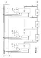
- Fig. 4 schematically shows the selection procedure of the relay terminals.
- the terminals s and d first determine the distance D sd which separates them.
- the terminal determines the set S s of its close neighbors: it calculates for this purpose the distances that separate it from the surrounding terminals and selects those located at less than D sd of it.
- the terminal d likewise determines the set S d of its close neighbors.
- the relay terminals r 1 , r 2 , .., r K are selected from the set S s ⁇ S d as those which minimize the sum D s - r k + D s - d k or D s - r k and D r - d k are the distances between s and r k on the one hand and r k and d on the other hand. If the set S s ⁇ S d is empty, the cooperation procedure is aborted. If the set S s ⁇ S d contains a number K ' ⁇ K of terminals, a cooperation strategy K ' relay can be adopted after consultation between the source terminal and the destination terminal.
- the relay terminals are selected on the basis of an error rate criterion (BER).
- BER error rate criterion
- the source terminal transmits a predetermined sequence of control symbols to the surrounding terminals. This sequence is known to all the terminals and each terminal that receives it can thus determine its BER. Those whose BER is below a threshold value then send an acknowledgment message to the terminal source, possibly specifying the measured error rate range and / or the terminal load.
- the source terminal selects relay terminals r k having reported the lowest BERs.
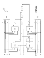
- Fig. 5 represents the general structure of a source terminal according to one embodiment of the invention.
- the bus carrying the 4K information symbols s 1 , s 2 , ..., s 4K is represented at 500 , each symbol being transported on M son corresponding to the M components.
- the source terminal comprises K modules 510 operating in parallel on the 4K information symbols, each module 510 receiving a vector pair V k , V 1 k specific, that is to say 4K coefficients, previously stored in a memory, via a second bus 505 not detailed.
- a module 510 receiving the components of the vectors V k , V 1 k sequentially supplies on its output the transmission symbols of the k th frame in the order vs 2 k , vs 4 k , vs 1 k , vs 3 k
- Each delay line is produced for example by means of M shift registers operating in parallel, clocked at the frequency 1 / T S and of length 4.
- the transmission symbols appearing at the output 530 are then used to modulate a UWB signal as described in relation to the expressions (9) and (9 ').
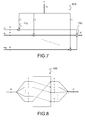
- Fig. 6 shows the general structure of a module 510 of FIG. 5 and more precisely the module 510 generating the transmission symbols of the k th frame.
- this module receives from the bus 530 the information symbols s 1 , s 2 , ..., s 4K .
- the bus is represented in two sub-buses 631 and 632 respectively carrying the symbols S 1 ,..., S K , S K + 1 , .., s 2K and s 2K + 1 , .. , s 3K , s 3K + 1 , .., s 4K , that is ⁇ 12 and ⁇ 34 .
- the module 510 comprises four sub-modules 610 of identical structure, two of these submodules receiving as input the symbols s 1 , .., s K , s K + 1 , .., s 2K and the other two the symbols S 2K + 1 , .., S 3K , S 3K + 1 , .., S 4K .
- the two submodules 610 receiving the symbols S 1 ,..., S K , S K + 1 ,..., S 2K , one receives a vector the vector V k and generates the symbol vs 4 k , , the other the vector V 1 k and generates the symbol vs 1 k . .
- the two submodules 610 receiving the symbols s 2K + 1 , ⁇ , s 3K , s 3K + 1 , ⁇ , s 4K , one receives the vector V k and the other the vector V 1 k . .
- the one receiving the vector V 1 k generates the symbol vs 2 k . .
- the one receiving the vector V k generates a symbol whose PPM components are subject to permutation and possibly to a sign change in the submodule 630.
- the submodule 630 generates the symbol vs 3 k .
- Sub-module 610 providing the symbol vs 2 k is directly connected to the output 640 and the outputs of the other submodules are connected to respective inputs of three series-connected delay lines 620, each applying an identical delay equal to the symbol time T S.
- the transmission symbols vs 2 k , vs 4 k , vs 1 k , vs 3 k appear successively on the output 640, the transmission symbols vs 2 k , vs 4 k , vs 1 k , vs 3 k in accordance with the symbol sequence illustrated in FIG. 2.
- Fig. 7 schematically illustrates the structure of a module 610. It receives as input a vector V of dimension of 2 K , for example V k or V 1 k and 2 K vectors e 1 , ..., e K , e K + 1 , .., e 2K of dimension M , for example s 1 , .., s K , s K + 1 , .., s 2K or S 2K + 1 , .., s 3K , S 3K + 1 , .., s 4K .
- V of dimension of 2 K for example V k or V 1 k and 2 K vectors e 1 , ..., e K , e K + 1 , .., e 2K of dimension M , for example s 1 , .., s K , s K + 1 , .., s 2K or S 2K + 1 , .., s 3K , S 3
- the 2 K scalar components of V are respectively multiplied with the vectors e 1 , ..., e K , e K + 1 , .., e 2K by means of the multipliers 710.
- the vectors thus obtained are then summed by the summator 720 .
- Fig. 8 schematically illustrates the structure of the submodule 630 of the module 510, according to an exemplary embodiment.
- This submodule performs the multiplication operation by the matrix ⁇ , namely a permutation of the M input components, possibly accompanied by a sign change of one or a plurality of these components.
- the example illustrated in FIG. 8 corresponds to a simple circular shift of the components.
- the architecture of the source terminal may have numerous variants, in particular those induced within the modules 510 by an exchange of transmission symbols. vs 1 k and vs 4 k or / and transmission symbols vs 2 k and vs 3 k in the spatio-temporal code. They result in exchange / branch exchanges at the input of the delay lines 620.
- the UWB signals transmitted by the source terminal during the first half-frames are repeated by the relay terminals in the second half-frames according to a conventional AF protocol.
- the invention does not require in this respect a modification of the relay terminals.
- the UWB signals transmitted by the source terminal, retransmitted by the relay terminals can be processed by a destination terminal in a conventional manner by a MIMO receiver.
- the receiver may for example comprise a correlation stage of the type Rake followed by a decision stage, using for example a sphere decoder known to those skilled in the art.
Landscapes
- Engineering & Computer Science (AREA)
- Computer Networks & Wireless Communication (AREA)
- Signal Processing (AREA)
- Mobile Radio Communication Systems (AREA)
- Radio Transmission System (AREA)
- Radio Relay Systems (AREA)
- Dc Digital Transmission (AREA)
- Compression, Expansion, Code Conversion, And Decoders (AREA)
- Vehicle Body Suspensions (AREA)
- Supply And Distribution Of Alternating Current (AREA)
- Optical Communication System (AREA)
Applications Claiming Priority (1)
| Application Number | Priority Date | Filing Date | Title |
|---|---|---|---|
| FR0652034A FR2901932B1 (fr) | 2006-06-06 | 2006-06-06 | Systeme de communication uwb cooperatif de type coherant |
Publications (3)
| Publication Number | Publication Date |
|---|---|
| EP1865613A2 true EP1865613A2 (de) | 2007-12-12 |
| EP1865613A3 EP1865613A3 (de) | 2008-02-27 |
| EP1865613B1 EP1865613B1 (de) | 2010-03-17 |
Family
ID=37686065
Family Applications (1)
| Application Number | Title | Priority Date | Filing Date |
|---|---|---|---|
| EP07109489A Not-in-force EP1865613B1 (de) | 2006-06-06 | 2007-06-04 | UWB kooperatives kohärentes Nachrichtentechniksystem |
Country Status (9)
| Country | Link |
|---|---|
| US (1) | US7864831B2 (de) |
| EP (1) | EP1865613B1 (de) |
| JP (1) | JP5196877B2 (de) |
| KR (1) | KR101367440B1 (de) |
| CN (1) | CN101087183B (de) |
| AT (1) | ATE461557T1 (de) |
| DE (1) | DE602007005304D1 (de) |
| ES (1) | ES2342205T3 (de) |
| FR (1) | FR2901932B1 (de) |
Families Citing this family (21)
| Publication number | Priority date | Publication date | Assignee | Title |
|---|---|---|---|---|
| FR2899042B1 (fr) * | 2006-03-21 | 2008-05-02 | Commissariat Energie Atomique | Procede de codage spatio-temporel pour systeme de communication bi-antenne de type uwb impulsionnel |
| FR2906659B1 (fr) * | 2006-10-03 | 2008-12-19 | Commissariat Energie Atomique | Procede de codage spatio-temporel pour systeme de communication multi-antenne de type uwb impulsionnel. |
| FR2913160B1 (fr) * | 2007-02-27 | 2009-05-22 | Commissariat Energie Atomique | Decodeur a maximum de vraisemblance pour systeme multi-source a modulation de position d'impulsion |
| FR2916590B1 (fr) * | 2007-05-21 | 2009-10-09 | Commissariat Energie Atomique | Systeme de communication mimo uwb de type incoherent. |
| JP2009081846A (ja) * | 2007-09-02 | 2009-04-16 | Mitsubishi Electric R & D Centre Europa Bv | ネスト化チャネルを介して受信信号のp長ベクトルを受信するシステム及び受信機 |
| FR2923105B1 (fr) * | 2007-10-25 | 2009-12-11 | Commissariat Energie Atomique | Procede de codage spatio-temporel utilisant un alphabet de modulation de position partitionne. |
| JP5059588B2 (ja) * | 2007-12-27 | 2012-10-24 | 京セラ株式会社 | 無線通信システム、移動局、基地局、無線通信方法 |
| FR2927205A1 (fr) * | 2008-01-31 | 2009-08-07 | Commissariat Energie Atomique | Procede de codage spatio-temporel a faible papr pour systeme de communication multi-antenne de type uwb impulsionnel |
| TW201004214A (en) * | 2008-07-04 | 2010-01-16 | Inst Information Industry | Communication apparatuses, transmission method, receiving method of a wireless network system for hybrid automatic repeat request and tangible machine-readable medium thereof |
| EP2293466B1 (de) * | 2009-09-03 | 2013-08-28 | Mitsubishi Electric R&D Centre Europe B.V. | Verfahren und Vorrichtung zum Weiterschalten von Symbolen, die durch eine Quelle zu einem Ziel übertragen wurden |
| EP2481164A1 (de) * | 2009-09-24 | 2012-08-01 | Universität Duisburg-Essen | Verfahren, relaisstation und system zur signalübertragung zwischen einer ersten signalquelle und einer zweiten signalquelle |
| US8750420B2 (en) * | 2009-11-16 | 2014-06-10 | Custom Link Corporation | Method and apparatus for generating modulated radio waves |
| US8787824B2 (en) * | 2011-09-21 | 2014-07-22 | Telefonaktiebolaget L M Ericsson (Publ) | System and method for determining repeater gain |
| CN106130637B (zh) * | 2016-07-26 | 2018-06-01 | 桂林电子科技大学 | 一种基于led的可见光通信系统和方法 |
| US10142137B2 (en) | 2017-03-02 | 2018-11-27 | Micron Technology, Inc. | Wireless devices and systems including examples of full duplex transmission |
| US11941516B2 (en) | 2017-08-31 | 2024-03-26 | Micron Technology, Inc. | Cooperative learning neural networks and systems |
| US10554375B2 (en) | 2017-09-11 | 2020-02-04 | Micron Technology, Inc. | Full duplex device-to-device cooperative communication |
| US11206050B2 (en) | 2018-02-06 | 2021-12-21 | Micron Technology, Inc. | Self interference noise cancellation to support multiple frequency bands |
| US10979097B2 (en) | 2019-09-05 | 2021-04-13 | Micron Technology, Inc. | Wireless devices and systems including examples of full duplex transmission using neural networks or recurrent neural networks |
| US11258473B2 (en) | 2020-04-14 | 2022-02-22 | Micron Technology, Inc. | Self interference noise cancellation to support multiple frequency bands with neural networks or recurrent neural networks |
| CN117063506A (zh) | 2021-01-08 | 2023-11-14 | 株式会社Ntt都科摩 | 终端、无线通信方法以及基站 |
Family Cites Families (8)
| Publication number | Priority date | Publication date | Assignee | Title |
|---|---|---|---|---|
| AU2002345190A1 (en) * | 2001-06-28 | 2003-03-03 | King's College London | Electronic data communication system |
| US7321601B2 (en) * | 2001-09-26 | 2008-01-22 | General Atomics | Method and apparatus for data transfer using a time division multiple frequency scheme supplemented with polarity modulation |
| US7289494B2 (en) * | 2001-12-06 | 2007-10-30 | Pulse-Link, Inc. | Systems and methods for wireless communication over a wide bandwidth channel using a plurality of sub-channels |
| US7099422B2 (en) * | 2002-04-19 | 2006-08-29 | General Electric Company | Synchronization of ultra-wideband communications using a transmitted-reference preamble |
| US7379447B2 (en) * | 2003-05-02 | 2008-05-27 | Microsoft Corporation | Slotted seeded channel hopping for capacity improvement in wireless networks |
| FR2899042B1 (fr) * | 2006-03-21 | 2008-05-02 | Commissariat Energie Atomique | Procede de codage spatio-temporel pour systeme de communication bi-antenne de type uwb impulsionnel |
| FR2899745B1 (fr) * | 2006-04-07 | 2008-05-30 | Commissariat Energie Atomique | Procede de codage spatio-temporel pour systeme de communication multi-antenne de type uwb impulsionnel |
| FR2900775B1 (fr) * | 2006-05-02 | 2008-06-13 | Commissariat Energie Atomique | Systeme de communication uwb cooperatif de type non-coherent |
-
2006
- 2006-06-06 FR FR0652034A patent/FR2901932B1/fr not_active Expired - Fee Related
-
2007
- 2007-06-04 ES ES07109489T patent/ES2342205T3/es active Active
- 2007-06-04 AT AT07109489T patent/ATE461557T1/de not_active IP Right Cessation
- 2007-06-04 DE DE602007005304T patent/DE602007005304D1/de active Active
- 2007-06-04 EP EP07109489A patent/EP1865613B1/de not_active Not-in-force
- 2007-06-04 US US11/757,622 patent/US7864831B2/en not_active Expired - Fee Related
- 2007-06-05 JP JP2007149455A patent/JP5196877B2/ja not_active Expired - Fee Related
- 2007-06-05 KR KR1020070054944A patent/KR101367440B1/ko not_active Expired - Fee Related
- 2007-06-06 CN CN2007101107504A patent/CN101087183B/zh not_active Expired - Fee Related
Non-Patent Citations (4)
| Title |
|---|
| ABOU-RJEILY C ET AL: "Space-Time Coding for Multiuser Ultra-Wideband Communications" INTERNET CITATION, [Online] 13 septembre 2005 (2005-09-13), XP002407955 Extrait de l'Internet: URL:http://www.comelec.enst.fr/ belfiore/UWB_MIMO.pdf> [extrait le 2006-11-16] * |
| SHARMA G V V ET AL: "Diversity Gain Using a Repeater in a Wireless Personal Area Network" VEHICULAR TECHNOLOGY CONFERENCE, 2005. VTC 2005-SPRING. 2005 IEEE 61ST STOCKHOLM, SWEDEN 30-01 MAY 2005, PISCATAWAY, NJ, USA,IEEE, 30 mai 2005 (2005-05-30), pages 1519-1522, XP010855676 ISBN: 0-7803-8887-9 * |
| SHENG YANG ET AL: "Optimal Space-Time Codes for the MIMO Amplify-and-Forward Cooperative Channel" COMMUNICATIONS, 2006 INTERNATIONAL ZURICH SEMINAR ON ZURICH, SWITZERLAND FEBRUARY 22-24, 2006, PISCATAWAY, NJ, USA,IEEE, 22 février 2006 (2006-02-22), pages 122-125, XP010924253 ISBN: 1-4244-0092-9 * |
| THOMAS J: "Efficient distributed signaling schemes for cooperative wireless networks" VEHICULAR TECHNOLOGY CONFERENCE, 2004. VTC2004-FALL. 2004 IEEE 60TH LOS ANGELES, CA, USA 26-29 SEPT. 2004, PISCATAWAY, NJ, USA,IEEE, 26 septembre 2004 (2004-09-26), pages 1018-1022, XP010786776 ISBN: 0-7803-8521-7 * |
Also Published As
| Publication number | Publication date |
|---|---|
| FR2901932A1 (fr) | 2007-12-07 |
| EP1865613B1 (de) | 2010-03-17 |
| DE602007005304D1 (de) | 2010-04-29 |
| US7864831B2 (en) | 2011-01-04 |
| KR101367440B1 (ko) | 2014-03-11 |
| US20070280333A1 (en) | 2007-12-06 |
| FR2901932B1 (fr) | 2008-09-05 |
| EP1865613A3 (de) | 2008-02-27 |
| ATE461557T1 (de) | 2010-04-15 |
| CN101087183B (zh) | 2012-07-04 |
| JP5196877B2 (ja) | 2013-05-15 |
| JP2007329928A (ja) | 2007-12-20 |
| KR20070116736A (ko) | 2007-12-11 |
| CN101087183A (zh) | 2007-12-12 |
| ES2342205T3 (es) | 2010-07-02 |
Similar Documents
| Publication | Publication Date | Title |
|---|---|---|
| EP1865613B1 (de) | UWB kooperatives kohärentes Nachrichtentechniksystem | |
| EP1852980B1 (de) | Kooperatives, inkohärentes UWB-Kommunikationssystem | |
| EP2245751B1 (de) | Verfahren zur räumlich-zeitlichen codierung mit niedrigen papr für ein mehrantennen-kommunikationssystem des impuls-uwb-typs | |
| EP2005608B1 (de) | Verfahren zur räumlich-zeitlichen codierung für ein zweiantennen-kommunikationssystem des gepulsten uwb-typs | |
| FR2715523A1 (fr) | Récepteur et procédé de réception pour un système d'accès multiple par répartition par code. | |
| EP2070199B1 (de) | Verfahren zur räumlichen und zeitlichen kodierung für eine mehrantennen-kommunikationsvorrichtung mit uwb-impulsen | |
| EP2026475A1 (de) | Raum-Zeit-Kodier-/Dekodierverfahren für Mehrfachantennen-Kommunikationssystem vom Impulstyp | |
| EP2099137A2 (de) | Differentielles Raum-Zeit-Kodierverfahren | |
| FR3023102A1 (fr) | Procede de transmission dynamique et selectif fd-dsdf d'un signal numerique pour un systeme mamrc avec plusieurs relais full-duplex, produit programme et dispositif relais correspondants | |
| WO2008040716A1 (fr) | Procédé de codage spatio-temporel pour système de communication multi-antenne de type uwb impulsionnel | |
| EP3871385B1 (de) | Übertragungsverfahren für pilotsymbole | |
| EP1668794B1 (de) | Verfahren zur mehrantennenemission eines raum-zeit-block-kodierten signales | |
| EP2122892B1 (de) | Verfahren zur raum-zeit-kodierung für ein kommunikationssystem mit mehreren antennen und welches ultrabreitbandpulse verwendet | |
| EP1748577B1 (de) | Verfahren und Vorrichtung zur mehrantennen Ultrabreitbandkommunikation mittels Hermite Impulsen | |
| EP3917024A1 (de) | Demodulationsverfahren durch automatisches lernen für mimo-empfänger mit energieerfassung | |
| EP1995883A1 (de) | MIMO-UWB-Kommunikationssystem vom inkohärenten Typ | |
| EP2053814B1 (de) | Verfahren zur Raum-Zeit-Kodierung mittels eines gespaltenen Position-Modulation-Alphabets | |
| EP1681819A1 (de) | Vielfachantennensystem | |
| EP3503413A1 (de) | Multiantennen-impuls-uwb-empfänger | |
| FR2823623A1 (fr) | Procede de transmission bidirectionnelle de signaux multiporteuses, systeme terminal de communication et signal correspondants | |
| EP1982429B1 (de) | Mehrfachzugangskommunikation auf der Basis einer Impuls-Ultrabreitband-Bitübertragungsschicht | |
| Jerbi | Non-coherent detection of continuous phase modulation for low earth orbit satellite IoT communications affected by Doppler shift | |
| EP1128590A1 (de) | Synchronisierungssystem für ein digitales telekommunikationssystem mit vielfachzugriff | |
| WO2017114915A1 (fr) | Procede d'association univalente et univoque entre emetteurs et recepteurs de transmission a partir du canal de propagation | |
| WO2017098170A1 (fr) | Procédé et dispositif de combinaison de trames de symboles complexes |
Legal Events
| Date | Code | Title | Description |
|---|---|---|---|
| PUAI | Public reference made under article 153(3) epc to a published international application that has entered the european phase |
Free format text: ORIGINAL CODE: 0009012 |
|
| AK | Designated contracting states |
Kind code of ref document: A2 Designated state(s): AT BE BG CH CY CZ DE DK EE ES FI FR GB GR HU IE IS IT LI LT LU LV MC MT NL PL PT RO SE SI SK TR |
|
| AX | Request for extension of the european patent |
Extension state: AL BA HR MK YU |
|
| PUAL | Search report despatched |
Free format text: ORIGINAL CODE: 0009013 |
|
| AK | Designated contracting states |
Kind code of ref document: A3 Designated state(s): AT BE BG CH CY CZ DE DK EE ES FI FR GB GR HU IE IS IT LI LT LU LV MC MT NL PL PT RO SE SI SK TR |
|
| AX | Request for extension of the european patent |
Extension state: AL BA HR MK YU |
|
| 17P | Request for examination filed |
Effective date: 20080725 |
|
| AKX | Designation fees paid |
Designated state(s): AT BE BG CH CY CZ DE DK EE ES FI FR GB GR HU IE IS IT LI LT LU LV MC MT NL PL PT RO SE SI SK TR |
|
| GRAP | Despatch of communication of intention to grant a patent |
Free format text: ORIGINAL CODE: EPIDOSNIGR1 |
|
| GRAS | Grant fee paid |
Free format text: ORIGINAL CODE: EPIDOSNIGR3 |
|
| GRAA | (expected) grant |
Free format text: ORIGINAL CODE: 0009210 |
|
| AK | Designated contracting states |
Kind code of ref document: B1 Designated state(s): AT BE BG CH CY CZ DE DK EE ES FI FR GB GR HU IE IS IT LI LT LU LV MC MT NL PL PT RO SE SI SK TR |
|
| REG | Reference to a national code |
Ref country code: GB Ref legal event code: FG4D Free format text: NOT ENGLISH |
|
| REG | Reference to a national code |
Ref country code: CH Ref legal event code: EP |
|
| REG | Reference to a national code |
Ref country code: IE Ref legal event code: FG4D |
|
| REF | Corresponds to: |
Ref document number: 602007005304 Country of ref document: DE Date of ref document: 20100429 Kind code of ref document: P |
|
| REG | Reference to a national code |
Ref country code: SE Ref legal event code: TRGR |
|
| REG | Reference to a national code |
Ref country code: ES Ref legal event code: FG2A Ref document number: 2342205 Country of ref document: ES Kind code of ref document: T3 |
|
| REG | Reference to a national code |
Ref country code: NL Ref legal event code: VDEP Effective date: 20100317 |
|
| PG25 | Lapsed in a contracting state [announced via postgrant information from national office to epo] |
Ref country code: LT Free format text: LAPSE BECAUSE OF FAILURE TO SUBMIT A TRANSLATION OF THE DESCRIPTION OR TO PAY THE FEE WITHIN THE PRESCRIBED TIME-LIMIT Effective date: 20100317 |
|
| LTIE | Lt: invalidation of european patent or patent extension |
Effective date: 20100317 |
|
| PG25 | Lapsed in a contracting state [announced via postgrant information from national office to epo] |
Ref country code: AT Free format text: LAPSE BECAUSE OF FAILURE TO SUBMIT A TRANSLATION OF THE DESCRIPTION OR TO PAY THE FEE WITHIN THE PRESCRIBED TIME-LIMIT Effective date: 20100317 Ref country code: FI Free format text: LAPSE BECAUSE OF FAILURE TO SUBMIT A TRANSLATION OF THE DESCRIPTION OR TO PAY THE FEE WITHIN THE PRESCRIBED TIME-LIMIT Effective date: 20100317 Ref country code: LV Free format text: LAPSE BECAUSE OF FAILURE TO SUBMIT A TRANSLATION OF THE DESCRIPTION OR TO PAY THE FEE WITHIN THE PRESCRIBED TIME-LIMIT Effective date: 20100317 Ref country code: PL Free format text: LAPSE BECAUSE OF FAILURE TO SUBMIT A TRANSLATION OF THE DESCRIPTION OR TO PAY THE FEE WITHIN THE PRESCRIBED TIME-LIMIT Effective date: 20100317 Ref country code: SI Free format text: LAPSE BECAUSE OF FAILURE TO SUBMIT A TRANSLATION OF THE DESCRIPTION OR TO PAY THE FEE WITHIN THE PRESCRIBED TIME-LIMIT Effective date: 20100317 |
|
| REG | Reference to a national code |
Ref country code: IE Ref legal event code: FD4D |
|
| PG25 | Lapsed in a contracting state [announced via postgrant information from national office to epo] |
Ref country code: GR Free format text: LAPSE BECAUSE OF FAILURE TO SUBMIT A TRANSLATION OF THE DESCRIPTION OR TO PAY THE FEE WITHIN THE PRESCRIBED TIME-LIMIT Effective date: 20100618 Ref country code: RO Free format text: LAPSE BECAUSE OF FAILURE TO SUBMIT A TRANSLATION OF THE DESCRIPTION OR TO PAY THE FEE WITHIN THE PRESCRIBED TIME-LIMIT Effective date: 20100317 Ref country code: CY Free format text: LAPSE BECAUSE OF FAILURE TO SUBMIT A TRANSLATION OF THE DESCRIPTION OR TO PAY THE FEE WITHIN THE PRESCRIBED TIME-LIMIT Effective date: 20100317 Ref country code: EE Free format text: LAPSE BECAUSE OF FAILURE TO SUBMIT A TRANSLATION OF THE DESCRIPTION OR TO PAY THE FEE WITHIN THE PRESCRIBED TIME-LIMIT Effective date: 20100317 Ref country code: NL Free format text: LAPSE BECAUSE OF FAILURE TO SUBMIT A TRANSLATION OF THE DESCRIPTION OR TO PAY THE FEE WITHIN THE PRESCRIBED TIME-LIMIT Effective date: 20100317 |
|
| PG25 | Lapsed in a contracting state [announced via postgrant information from national office to epo] |
Ref country code: CZ Free format text: LAPSE BECAUSE OF FAILURE TO SUBMIT A TRANSLATION OF THE DESCRIPTION OR TO PAY THE FEE WITHIN THE PRESCRIBED TIME-LIMIT Effective date: 20100317 Ref country code: SK Free format text: LAPSE BECAUSE OF FAILURE TO SUBMIT A TRANSLATION OF THE DESCRIPTION OR TO PAY THE FEE WITHIN THE PRESCRIBED TIME-LIMIT Effective date: 20100317 Ref country code: IS Free format text: LAPSE BECAUSE OF FAILURE TO SUBMIT A TRANSLATION OF THE DESCRIPTION OR TO PAY THE FEE WITHIN THE PRESCRIBED TIME-LIMIT Effective date: 20100717 Ref country code: BG Free format text: LAPSE BECAUSE OF FAILURE TO SUBMIT A TRANSLATION OF THE DESCRIPTION OR TO PAY THE FEE WITHIN THE PRESCRIBED TIME-LIMIT Effective date: 20100617 |
|
| BERE | Be: lapsed |
Owner name: COMMISSARIAT A L'ENERGIE ATOMIQUE Effective date: 20100630 |
|
| PLBE | No opposition filed within time limit |
Free format text: ORIGINAL CODE: 0009261 |
|
| STAA | Information on the status of an ep patent application or granted ep patent |
Free format text: STATUS: NO OPPOSITION FILED WITHIN TIME LIMIT |
|
| PG25 | Lapsed in a contracting state [announced via postgrant information from national office to epo] |
Ref country code: MC Free format text: LAPSE BECAUSE OF NON-PAYMENT OF DUE FEES Effective date: 20100630 Ref country code: PT Free format text: LAPSE BECAUSE OF FAILURE TO SUBMIT A TRANSLATION OF THE DESCRIPTION OR TO PAY THE FEE WITHIN THE PRESCRIBED TIME-LIMIT Effective date: 20100719 Ref country code: IE Free format text: LAPSE BECAUSE OF FAILURE TO SUBMIT A TRANSLATION OF THE DESCRIPTION OR TO PAY THE FEE WITHIN THE PRESCRIBED TIME-LIMIT Effective date: 20100317 Ref country code: DK Free format text: LAPSE BECAUSE OF FAILURE TO SUBMIT A TRANSLATION OF THE DESCRIPTION OR TO PAY THE FEE WITHIN THE PRESCRIBED TIME-LIMIT Effective date: 20100317 |
|
| 26N | No opposition filed |
Effective date: 20101220 |
|
| PG25 | Lapsed in a contracting state [announced via postgrant information from national office to epo] |
Ref country code: IT Free format text: LAPSE BECAUSE OF NON-PAYMENT OF DUE FEES Effective date: 20100604 |
|
| PG25 | Lapsed in a contracting state [announced via postgrant information from national office to epo] |
Ref country code: MT Free format text: LAPSE BECAUSE OF FAILURE TO SUBMIT A TRANSLATION OF THE DESCRIPTION OR TO PAY THE FEE WITHIN THE PRESCRIBED TIME-LIMIT Effective date: 20100317 |
|
| PG25 | Lapsed in a contracting state [announced via postgrant information from national office to epo] |
Ref country code: BE Free format text: LAPSE BECAUSE OF NON-PAYMENT OF DUE FEES Effective date: 20100630 |
|
| REG | Reference to a national code |
Ref country code: CH Ref legal event code: PL |
|
| PG25 | Lapsed in a contracting state [announced via postgrant information from national office to epo] |
Ref country code: CH Free format text: LAPSE BECAUSE OF NON-PAYMENT OF DUE FEES Effective date: 20110630 Ref country code: LI Free format text: LAPSE BECAUSE OF NON-PAYMENT OF DUE FEES Effective date: 20110630 |
|
| PG25 | Lapsed in a contracting state [announced via postgrant information from national office to epo] |
Ref country code: HU Free format text: LAPSE BECAUSE OF FAILURE TO SUBMIT A TRANSLATION OF THE DESCRIPTION OR TO PAY THE FEE WITHIN THE PRESCRIBED TIME-LIMIT Effective date: 20100918 Ref country code: LU Free format text: LAPSE BECAUSE OF NON-PAYMENT OF DUE FEES Effective date: 20100604 |
|
| PG25 | Lapsed in a contracting state [announced via postgrant information from national office to epo] |
Ref country code: TR Free format text: LAPSE BECAUSE OF FAILURE TO SUBMIT A TRANSLATION OF THE DESCRIPTION OR TO PAY THE FEE WITHIN THE PRESCRIBED TIME-LIMIT Effective date: 20100317 |
|
| REG | Reference to a national code |
Ref country code: FR Ref legal event code: PLFP Year of fee payment: 9 |
|
| PGFP | Annual fee paid to national office [announced via postgrant information from national office to epo] |
Ref country code: SE Payment date: 20150617 Year of fee payment: 9 Ref country code: GB Payment date: 20150619 Year of fee payment: 9 Ref country code: DE Payment date: 20150612 Year of fee payment: 9 Ref country code: ES Payment date: 20150629 Year of fee payment: 9 |
|
| PGFP | Annual fee paid to national office [announced via postgrant information from national office to epo] |
Ref country code: IT Payment date: 20150612 Year of fee payment: 9 |
|
| PGFP | Annual fee paid to national office [announced via postgrant information from national office to epo] |
Ref country code: FR Payment date: 20150630 Year of fee payment: 9 |
|
| REG | Reference to a national code |
Ref country code: DE Ref legal event code: R119 Ref document number: 602007005304 Country of ref document: DE |
|
| REG | Reference to a national code |
Ref country code: SE Ref legal event code: EUG |
|
| PG25 | Lapsed in a contracting state [announced via postgrant information from national office to epo] |
Ref country code: SE Free format text: LAPSE BECAUSE OF NON-PAYMENT OF DUE FEES Effective date: 20160605 |
|
| GBPC | Gb: european patent ceased through non-payment of renewal fee |
Effective date: 20160604 |
|
| REG | Reference to a national code |
Ref country code: FR Ref legal event code: ST Effective date: 20170228 |
|
| PG25 | Lapsed in a contracting state [announced via postgrant information from national office to epo] |
Ref country code: DE Free format text: LAPSE BECAUSE OF NON-PAYMENT OF DUE FEES Effective date: 20170103 Ref country code: FR Free format text: LAPSE BECAUSE OF NON-PAYMENT OF DUE FEES Effective date: 20160630 |
|
| PG25 | Lapsed in a contracting state [announced via postgrant information from national office to epo] |
Ref country code: GB Free format text: LAPSE BECAUSE OF NON-PAYMENT OF DUE FEES Effective date: 20160604 |
|
| PG25 | Lapsed in a contracting state [announced via postgrant information from national office to epo] |
Ref country code: IT Free format text: LAPSE BECAUSE OF NON-PAYMENT OF DUE FEES Effective date: 20160604 |
|
| PG25 | Lapsed in a contracting state [announced via postgrant information from national office to epo] |
Ref country code: ES Free format text: LAPSE BECAUSE OF NON-PAYMENT OF DUE FEES Effective date: 20160605 |
|
| REG | Reference to a national code |
Ref country code: ES Ref legal event code: FD2A Effective date: 20181204 |