EP1865331A2 - Electric/electronic device - Google Patents
Electric/electronic device Download PDFInfo
- Publication number
- EP1865331A2 EP1865331A2 EP07004986A EP07004986A EP1865331A2 EP 1865331 A2 EP1865331 A2 EP 1865331A2 EP 07004986 A EP07004986 A EP 07004986A EP 07004986 A EP07004986 A EP 07004986A EP 1865331 A2 EP1865331 A2 EP 1865331A2
- Authority
- EP
- European Patent Office
- Prior art keywords
- electronic device
- electrical
- circuit board
- load current
- hall sensor
- Prior art date
- Legal status (The legal status is an assumption and is not a legal conclusion. Google has not performed a legal analysis and makes no representation as to the accuracy of the status listed.)
- Withdrawn
Links
Images
Classifications
-
- G—PHYSICS
- G01—MEASURING; TESTING
- G01R—MEASURING ELECTRIC VARIABLES; MEASURING MAGNETIC VARIABLES
- G01R15/00—Details of measuring arrangements of the types provided for in groups G01R17/00 - G01R29/00, G01R33/00 - G01R33/26 or G01R35/00
- G01R15/14—Adaptations providing voltage or current isolation, e.g. for high-voltage or high-current networks
- G01R15/20—Adaptations providing voltage or current isolation, e.g. for high-voltage or high-current networks using galvano-magnetic devices, e.g. Hall-effect devices, i.e. measuring a magnetic field via the interaction between a current and a magnetic field, e.g. magneto resistive or Hall effect devices
- G01R15/202—Adaptations providing voltage or current isolation, e.g. for high-voltage or high-current networks using galvano-magnetic devices, e.g. Hall-effect devices, i.e. measuring a magnetic field via the interaction between a current and a magnetic field, e.g. magneto resistive or Hall effect devices using Hall-effect devices
-
- H—ELECTRICITY
- H05—ELECTRIC TECHNIQUES NOT OTHERWISE PROVIDED FOR
- H05K—PRINTED CIRCUITS; CASINGS OR CONSTRUCTIONAL DETAILS OF ELECTRIC APPARATUS; MANUFACTURE OF ASSEMBLAGES OF ELECTRICAL COMPONENTS
- H05K1/00—Printed circuits
- H05K1/18—Printed circuits structurally associated with non-printed electric components
- H05K1/181—Printed circuits structurally associated with non-printed electric components associated with surface mounted components
-
- G—PHYSICS
- G01—MEASURING; TESTING
- G01R—MEASURING ELECTRIC VARIABLES; MEASURING MAGNETIC VARIABLES
- G01R19/00—Arrangements for measuring currents or voltages or for indicating presence or sign thereof
- G01R19/0092—Measuring current only
-
- H—ELECTRICITY
- H05—ELECTRIC TECHNIQUES NOT OTHERWISE PROVIDED FOR
- H05K—PRINTED CIRCUITS; CASINGS OR CONSTRUCTIONAL DETAILS OF ELECTRIC APPARATUS; MANUFACTURE OF ASSEMBLAGES OF ELECTRICAL COMPONENTS
- H05K1/00—Printed circuits
- H05K1/02—Details
- H05K1/0213—Electrical arrangements not otherwise provided for
- H05K1/0263—High current adaptations, e.g. printed high current conductors or using auxiliary non-printed means; Fine and coarse circuit patterns on one circuit board
-
- H—ELECTRICITY
- H05—ELECTRIC TECHNIQUES NOT OTHERWISE PROVIDED FOR
- H05K—PRINTED CIRCUITS; CASINGS OR CONSTRUCTIONAL DETAILS OF ELECTRIC APPARATUS; MANUFACTURE OF ASSEMBLAGES OF ELECTRICAL COMPONENTS
- H05K1/00—Printed circuits
- H05K1/02—Details
- H05K1/0266—Marks, test patterns or identification means
- H05K1/0268—Marks, test patterns or identification means for electrical inspection or testing
-
- H—ELECTRICITY
- H05—ELECTRIC TECHNIQUES NOT OTHERWISE PROVIDED FOR
- H05K—PRINTED CIRCUITS; CASINGS OR CONSTRUCTIONAL DETAILS OF ELECTRIC APPARATUS; MANUFACTURE OF ASSEMBLAGES OF ELECTRICAL COMPONENTS
- H05K1/00—Printed circuits
- H05K1/02—Details
- H05K1/0296—Conductive pattern lay-out details not covered by sub groups H05K1/02 - H05K1/0295
- H05K1/0298—Multilayer circuits
-
- H—ELECTRICITY
- H05—ELECTRIC TECHNIQUES NOT OTHERWISE PROVIDED FOR
- H05K—PRINTED CIRCUITS; CASINGS OR CONSTRUCTIONAL DETAILS OF ELECTRIC APPARATUS; MANUFACTURE OF ASSEMBLAGES OF ELECTRICAL COMPONENTS
- H05K2201/00—Indexing scheme relating to printed circuits covered by H05K1/00
- H05K2201/10—Details of components or other objects attached to or integrated in a printed circuit board
- H05K2201/10007—Types of components
- H05K2201/10053—Switch
-
- H—ELECTRICITY
- H05—ELECTRIC TECHNIQUES NOT OTHERWISE PROVIDED FOR
- H05K—PRINTED CIRCUITS; CASINGS OR CONSTRUCTIONAL DETAILS OF ELECTRIC APPARATUS; MANUFACTURE OF ASSEMBLAGES OF ELECTRICAL COMPONENTS
- H05K2201/00—Indexing scheme relating to printed circuits covered by H05K1/00
- H05K2201/10—Details of components or other objects attached to or integrated in a printed circuit board
- H05K2201/10007—Types of components
- H05K2201/10151—Sensor
-
- Y—GENERAL TAGGING OF NEW TECHNOLOGICAL DEVELOPMENTS; GENERAL TAGGING OF CROSS-SECTIONAL TECHNOLOGIES SPANNING OVER SEVERAL SECTIONS OF THE IPC; TECHNICAL SUBJECTS COVERED BY FORMER USPC CROSS-REFERENCE ART COLLECTIONS [XRACs] AND DIGESTS
- Y02—TECHNOLOGIES OR APPLICATIONS FOR MITIGATION OR ADAPTATION AGAINST CLIMATE CHANGE
- Y02P—CLIMATE CHANGE MITIGATION TECHNOLOGIES IN THE PRODUCTION OR PROCESSING OF GOODS
- Y02P70/00—Climate change mitigation technologies in the production process for final industrial or consumer products
- Y02P70/50—Manufacturing or production processes characterised by the final manufactured product
Definitions
- the present invention is based on a designed according to the preamble of the main claim electrical / electronic device.
- Such electrical / electronic devices are generally intended to affect a variety of installed in buildings, connected to a bus system other electrical equipment (Venetian blinds, lighting equipment, household appliances, warning systems, etc.) as needed, or to monitor.
- a bus system other electrical equipment
- the most diverse electrical / electronic devices have become known.
- other electrical devices are mounted or arranged in the building so that their function or functional state can not be identified directly by the user.
- a lighting system is mounted in the outdoor area or in a long corridor area, the bulbs can not be seen directly by the user or a washing machine is placed in the basement of the building, so that the functional state of the washing machine for the user is not recognizable.
- the present invention seeks to provide a device in which in a simple manner a separation with appropriate isolation (creepage distance) between the load side and the bus side is realized and assigned to the Hall sensors Measuring and evaluation circuits are to provide in a particularly simple manner with the necessary energy.
- each load current path consists of two superposed conductor tracks 2a, 2b which are integrated for the purpose of their isolation in the printed circuit board material of the printed circuit board 1.
- each load current path is connected to a load terminal 3a, 3b fixed on the printed circuit board 1 and, on the other hand, to the switching contact of a relay 4 arranged on the printed circuit board 1.
- Each load current path is assigned a Hall sensor 6 for current measurement.
- substantially the upper insulation layer 5a contributes to the realization of the necessary creepage distance K to ensure the prescribed separation between the load current side and the low voltage bus side of the electrical / electronic equipment. With the measures described measures a 4 kV separation between the load current side and the bus side is achieved in a simple manner.
- the relay 4 is connected to its control side via a microcontroller 7 belonging to a bus coupling unit (not shown in detail for the sake of simplicity) with a bus connection 8 arranged on the printed circuit board 1.
- the Hall sensor 6 is also connected via a measurement evaluation 9 and the microcontroller 7 of the bus coupler to the bus connection 8.
- the two printed conductors 2a, 2b are integrated into the printed circuit board material or arranged on the inner layers of the printed circuit board 1.
- the circuit board 1 is made of epoxy resin glass fabric laminate FR4, whereby a simple insulation of the tracks 2a, 2b ensures a high insulation effect.
Landscapes
- Physics & Mathematics (AREA)
- General Physics & Mathematics (AREA)
- Engineering & Computer Science (AREA)
- Microelectronics & Electronic Packaging (AREA)
- Measuring Instrument Details And Bridges, And Automatic Balancing Devices (AREA)
Abstract
Es wird ein elektrisches/elektronisches Gerät, insbesondere ein Aktor für ein Bussystem der Gebäudesystemtechnik mit zumindest einem Laststrompfad vorgeschlagen, welchem zur Strommessung zumindest ein Hallsensor (6) zugeordnet ist. Zu dem Zweck, ein elektrisches/elektronisches Gerät zu schaffen, bei dem auf einfache Art und Weise eine Trennung mit entsprechender Isolation zwischen der Laststromseite und Busseite realisiert ist und die den Hallsensoren zugeordneten Mess- und Auswerteschaltungen auf besonders einfache Art und Weise mit der notwendigen Energie zu versorgen sind, ist der Laststrompfad im Bereich des Hallsensors als zumindest eine, von zumindest einer Isolationsschicht (5a,5b,5c) abgedeckten Leiterbahn (2a,2b) einer Leiterplatte (1) ausgeführt, und ist der Hallsensor unter Zwischenschaltung einer Isolationsschicht zumindest einer Leiterbahn zugeordnet.

Description
Die vorliegende Erfindung geht von einem gemäß Oberbegriff des Hauptanspruches konzipierten elektrischen/elektronischen Gerät aus.The present invention is based on a designed according to the preamble of the main claim electrical / electronic device.
Derartige elektrische/elektronische Geräte sind in der Regel dafür vorgesehen, eine Vielzahl von in Gebäuden installierte, an ein Bussystem angeschlossene weitere elektrische Geräte (Jalousieantriebe, Beleuchtungseinrichtungen, Haushaltsgeräte, Warnanlagen, usw.) bedarfsgerecht zu beeinflussen, bzw. zu überwachen. Zu diesem Zweck sind die unterschiedlichsten elektrischen/elektronischen Geräte bekannt geworden. Oftmals sind weitere elektrische Geräte so im Gebäude angebracht bzw. angeordnet, so dass deren Funktion bzw. Funktionszustand vom Benutzer nicht direkt ausgemacht werden kann. Beispielsweise ist eine Beleuchtungsanlage im Außenbereich oder in einem langen Flurbereich angebracht, wobei die Leuchtmittel vom Benutzer nicht direkt gesehen werden können oder eine Waschmaschine ist im Keller des Gebäudes aufgestellt, so dass der Funktionszustand der Waschmaschine für den Benutzer nicht erkennbar ist. Für den Benutzer ist es bei solchen Installationen deshalb oftmals wichtig zu erkennen, ob z. B. Leuchtmittel der Beleuchtungsanlage defekt sind bzw. die Waschmaschine mit ihrem Waschvorgang fertig ist. Aus diesem Gunde sind Geräte bekannt geworden, bei welchen unter Zuhilfenahme von Hallsensoren der Laststrom gemessen wird. D. h. mit Hilfe solcher Hallsensoren können zu Kontroll-, Mess-, Überwachungs- oder Meldezwecken zusätzliche Informationen, wie z. B. Leuchtmitteldefekt, Sicherung ausgefallen, Waschvorgang beendet, Schaltzustand Ein bzw. Aus in das Bussystem abgegeben und an zentraler Stelle zur Anzeige gebracht werden.Such electrical / electronic devices are generally intended to affect a variety of installed in buildings, connected to a bus system other electrical equipment (Venetian blinds, lighting equipment, household appliances, warning systems, etc.) as needed, or to monitor. For this purpose, the most diverse electrical / electronic devices have become known. Often, other electrical devices are mounted or arranged in the building so that their function or functional state can not be identified directly by the user. For example, a lighting system is mounted in the outdoor area or in a long corridor area, the bulbs can not be seen directly by the user or a washing machine is placed in the basement of the building, so that the functional state of the washing machine for the user is not recognizable. For the user, it is therefore often important in such installations to recognize whether z. B. bulbs of the lighting system are defective or the washing machine is done with their washing process. For this reason devices have become known in which the load current is measured with the aid of Hall sensors. Ie. With the help of such Hall sensors can for monitoring, measuring, monitoring or reporting purposes additional information, such. B. illuminant defect, fuse failed washing ended, switching state on or off in the bus system and placed at a central location for display.
Durch die
Ausgehend von einem derart ausgebildeten elektrischen/elektronischen Gerät liegt der vorliegenden Erfindung die Aufgabe zugrunde, ein Gerät zu schaffen, bei dem auf einfache Art und Weise eine Trennung mit entsprechender Isolation (Kriechstrecke) zwischen der Laststromseite und der Busseite realisiert ist und die den Hallsensoren zugeordneten Mess- und Auswerteschaltungen auf besonders einfache Art und Weise mit der notwendigen Energie zu versorgen sind.Starting from such a trained electrical / electronic device, the present invention seeks to provide a device in which in a simple manner a separation with appropriate isolation (creepage distance) between the load side and the bus side is realized and assigned to the Hall sensors Measuring and evaluation circuits are to provide in a particularly simple manner with the necessary energy.
Erfindungsgemäß wird diese Aufgabe durch die im Hauptanspruch angegebenen Merkmale gelöst.According to the invention this object is achieved by the features specified in the main claim.
Bei einer solchen Ausbildung ist besonders vorteilhaft, dass eine 4 kV Trennung zwischen dem zu messenden Laststrom und der Mess- und Auswerteschaltung der Busseite auf besonders einfache Art und Weise realisiert ist. Die Fertigung solcher Geräte ist einfach und kostengünstig, weil nur ein sehr geringer Anteil an Handarbeit anfällt. Zudem ist besonders vorteilhaft, dass bei einer derartigen Strommessung keine größeren Gehäuse oder zusätzlichen Leiterplatten bei identischer Anzahl zu überwachender Kanäle notwendig werden. Zudem können einfach durch Minderbestückungen Varianten ohne Strommessung hergestellt werden.In such a design is particularly advantageous that a 4 kV separation between the load current to be measured and the measurement and evaluation of the bus side is realized in a particularly simple manner. The production of such devices is simple and inexpensive, because only a very small proportion of manual labor is required. In addition, it is particularly advantageous that in such a current measurement no larger housing or additional circuit boards with an identical number of channels to be monitored are necessary. In addition, variants can be produced without current measurement simply by means of under-equipping.
Weitere vorteilhafte Ausgestaltungen des erfindungsgemäßen Gegenstandes sind in den Unteransprüchen angegeben. Anhand eines Ausführungsbeispiels sei die Erfindung im Prinzip näher erläutert. Dabei zeigt:
- Figur 1:
- einen Schnitt durch ein prinziphaft dargestelltes elektrisches/elektronisches Gerät;
- Figur 2:
- prinziphaft eine Unteransicht der Leiterplatte des elektrischen/elektronischen Gerät;
- Figur 3:
- prinziphaft die den Hallsensor und den Laststrompfad umgebende Schirmung.
- FIG. 1:
- a section through a principle illustrated electrical / electronic device;
- FIG. 2:
- principle, a bottom view of the circuit board of the electrical / electronic device;
- FIG. 3:
- in principle, the shield surrounding the Hall sensor and the load current path.
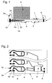
Wie aus den Figuren hervorgeht, weist ein solches, als mehrkanaliger Schaltaktor ausgeführtes elektrisches/elektronisches Gerät eine Leiterplatte 1 auf, in die je Kanal ein Laststrompfad integriert ist. Jeder Laststrompfad besteht aus zwei übereinander liegend angeordneten Leiterbahnen 2a, 2b die zum Zwecke ihrer Isolation in das Leiterplattenmaterial der Leiterplatte 1 integriert sind. Einerseits steht jeder Laststrompfad mit einer auf der Leiterplatte 1 festgelegten Lastklemme 3a, 3b und andererseits mit dem Schaltkontakt eines auf der Leiterplatte 1 angeordneten Relais 4 in Verbindung. Dadurch das die beiden Leiterbahnen 2a, 2b je Laststrompfad in die Leiterplatte 1 integriert sind, ergeben sich drei Isolationsschichten 5a, 5b, 5c, welche die Leiterbahnen 2a, 2b quasi vollständig aufnehmen. Jedem Laststrompfad ist ein Hallsensor 6 zur Strommessung zugeordnet. Von den drei Isolationsschichten 5a, 5b, 5c trägt im Wesentlichen die obere Isolationsschicht 5a zur Realisierung der notwendigen Kriechstrecke K bei, um die vorgeschriebene Trennung zwischen der Laststromseite und der mit Kleinspannung betriebenen Busseite des elektrischen/elektronischen Gerätes sicherzustellen. Mit den vorsehend beschriebenen Maßnahmen wird auf einfache Art und Weise eine 4 kV Trennung zwischen der Laststromseite und der Busseite erreicht.As can be seen from the figures, such, designed as a multi-channel switch actuator electrical / electronic device on a
Wie des weiteren insbesondere aus Figur 1 hervorgeht, steht das Relais 4 mit seiner Ansteuerseite über einen, zu einem, der Einfachheit halber nicht näher dargestellten Busankoppler gehörigen Mikrocontroller 7 mit einem auf der Leiterplatte 1 angeordneten Busanschluss 8 in Verbindung. Außerdem steht auch der Hallsensor 6 über eine Messauswertung 9 und den Mikrocontroller 7 des Busankopplers mit dem Busanschluss 8 in Verbindung.As can be further seen in particular from FIG. 1, the
Wie insbesondere aus Figur 2 hervorgeht, fließt der Laststrom von der Lastklemme 3a über die Anschlüsse 4a, 4b des -der Einfachheit halber nicht näher dargestellten-Schaltkontaktes des Relais 4. Vom Anschluss 4a aus wird der Laststrom zur Messung unter dem Hallsensor 6 hergeleitet und fließt danach zur Lastklemme 3b.As can be seen in particular from FIG. 2, the load current flows from the
Die beiden Leiterbahnen 2a, 2b sind wie bereits beschrieben in das Leiterplattenmaterial integriert bzw. auf den Innenlagen der Leiterplatte 1 angeordnet. Die Leiterplatte 1 besteht aus Epoxidharz-Glashartgewebe-Laminat FR4, wodurch bei einfacher Integration der Leiterbahnen 2a, 2b eine hohe Isolationswirkung gewährleistet ist.As already described, the two printed
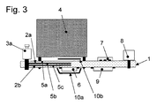
Wie insbesondere aus Figur 3 hervorgeht, ist dem Hallsensor 6 und in dessen Bereich den beiden Leiterbahnen 2a, 2b des Laststrompfades 2 eine Schirmung 10a, 10b zugeordnet, welche bewirkt, dass Strömungen durch Magnetfelder reduziert werden, die nicht durch den Laststrom hervorgerufen werden, der dem Hallsensor 6 zugeordnet ist. Insbesondere können Wechselfelder von Leitungen unter dem Gerät oder von Transformatoren neben dem Gerät teilweise abgeblockt werden.As can be seen in particular from FIG. 3, the
Claims (9)
Applications Claiming Priority (1)
| Application Number | Priority Date | Filing Date | Title |
|---|---|---|---|
| DE102006026148A DE102006026148A1 (en) | 2006-06-06 | 2006-06-06 | Electric / electronic device |
Publications (2)
| Publication Number | Publication Date |
|---|---|
| EP1865331A2 true EP1865331A2 (en) | 2007-12-12 |
| EP1865331A3 EP1865331A3 (en) | 2012-01-04 |
Family
ID=38480883
Family Applications (1)
| Application Number | Title | Priority Date | Filing Date |
|---|---|---|---|
| EP07004986A Withdrawn EP1865331A3 (en) | 2006-06-06 | 2007-03-10 | Electric/electronic device |
Country Status (2)
| Country | Link |
|---|---|
| EP (1) | EP1865331A3 (en) |
| DE (2) | DE102006026148A1 (en) |
Cited By (7)
| Publication number | Priority date | Publication date | Assignee | Title |
|---|---|---|---|---|
| WO2008025319A1 (en) * | 2006-08-30 | 2008-03-06 | Merten Gmbh & Co. Kg | Terminal unit of a bus system |
| WO2009148823A1 (en) * | 2008-06-02 | 2009-12-10 | Allegro Microsystems, Inc. | Arrangements for a current sensing circuit and integrated current sensor |
| WO2012152782A1 (en) * | 2011-05-12 | 2012-11-15 | BSH Bosch und Siemens Hausgeräte GmbH | Printed circuit board for a domestic appliance, domestic appliance, and a method for operating a domestic appliance |
| US8629520B2 (en) | 2006-01-20 | 2014-01-14 | Allegro Microsystems, Llc | Arrangements for an integrated sensor |
| US10935612B2 (en) | 2018-08-20 | 2021-03-02 | Allegro Microsystems, Llc | Current sensor having multiple sensitivity ranges |
| US11567108B2 (en) | 2021-03-31 | 2023-01-31 | Allegro Microsystems, Llc | Multi-gain channels for multi-range sensor |
| US11994541B2 (en) | 2022-04-15 | 2024-05-28 | Allegro Microsystems, Llc | Current sensor assemblies for low currents |
Families Citing this family (7)
| Publication number | Priority date | Publication date | Assignee | Title |
|---|---|---|---|---|
| US9013890B2 (en) | 2010-03-26 | 2015-04-21 | Infineon Technologies Ag | Semiconductor packages and methods for producing the same |
| US8400139B2 (en) | 2010-03-26 | 2013-03-19 | Infineon Technologies Ag | Sensor package having a sensor chip |
| US8969985B2 (en) * | 2011-08-30 | 2015-03-03 | Infineon Technologies Ag | Semiconductor chip package and method |
| US8860153B2 (en) | 2012-11-30 | 2014-10-14 | Infineon Technologies Ag | Semiconductor packages, systems, and methods of formation thereof |
| DE102013223888A1 (en) * | 2013-11-22 | 2015-05-28 | Zf Friedrichshafen Ag | Multifunctional High Current Circuit Board |
| JP2016539504A (en) | 2013-11-21 | 2016-12-15 | ツェットエフ、フリードリッヒスハーフェン、アクチエンゲゼルシャフトZf Friedrichshafen Ag | Multifunctional high current circuit board |
| EP2905626B1 (en) | 2014-02-05 | 2019-09-11 | ams AG | Integrated current sensor system and method for producing an integrated current sensor system |
Family Cites Families (3)
| Publication number | Priority date | Publication date | Assignee | Title |
|---|---|---|---|---|
| DE10392748B4 (en) * | 2002-06-18 | 2010-12-23 | Asahi Kasei Emd Corporation | Current measuring method and current measuring device |
| DE10253018B4 (en) | 2002-11-14 | 2013-02-28 | Abb Ag | Switching device and system and method for current measurement in the switching device |
| US7259545B2 (en) * | 2003-02-11 | 2007-08-21 | Allegro Microsystems, Inc. | Integrated sensor |
-
2006
- 2006-06-06 DE DE102006026148A patent/DE102006026148A1/en not_active Ceased
- 2006-06-06 DE DE202006020504U patent/DE202006020504U1/en not_active Expired - Lifetime
-
2007
- 2007-03-10 EP EP07004986A patent/EP1865331A3/en not_active Withdrawn
Cited By (15)
| Publication number | Priority date | Publication date | Assignee | Title |
|---|---|---|---|---|
| US9859489B2 (en) | 2006-01-20 | 2018-01-02 | Allegro Microsystems, Llc | Integrated circuit having first and second magnetic field sensing elements |
| US8952471B2 (en) | 2006-01-20 | 2015-02-10 | Allegro Microsystems, Llc | Arrangements for an integrated sensor |
| US9082957B2 (en) | 2006-01-20 | 2015-07-14 | Allegro Microsystems, Llc | Arrangements for an integrated sensor |
| US8629520B2 (en) | 2006-01-20 | 2014-01-14 | Allegro Microsystems, Llc | Arrangements for an integrated sensor |
| US10069063B2 (en) | 2006-01-20 | 2018-09-04 | Allegro Microsystems, Llc | Integrated circuit having first and second magnetic field sensing elements |
| WO2008025319A1 (en) * | 2006-08-30 | 2008-03-06 | Merten Gmbh & Co. Kg | Terminal unit of a bus system |
| CN102016606B (en) * | 2008-06-02 | 2013-10-30 | 阿莱戈微系统有限责任公司 | Arrangements for current sensing circuit and integrated current sensor |
| WO2009148823A1 (en) * | 2008-06-02 | 2009-12-10 | Allegro Microsystems, Inc. | Arrangements for a current sensing circuit and integrated current sensor |
| CN102016606A (en) * | 2008-06-02 | 2011-04-13 | 阿莱戈微系统公司 | Arrangements for a current sensing circuit and integrated current sensor |
| US7816905B2 (en) | 2008-06-02 | 2010-10-19 | Allegro Microsystems, Inc. | Arrangements for a current sensing circuit and integrated current sensor |
| WO2012152782A1 (en) * | 2011-05-12 | 2012-11-15 | BSH Bosch und Siemens Hausgeräte GmbH | Printed circuit board for a domestic appliance, domestic appliance, and a method for operating a domestic appliance |
| US10935612B2 (en) | 2018-08-20 | 2021-03-02 | Allegro Microsystems, Llc | Current sensor having multiple sensitivity ranges |
| US11567108B2 (en) | 2021-03-31 | 2023-01-31 | Allegro Microsystems, Llc | Multi-gain channels for multi-range sensor |
| US11994541B2 (en) | 2022-04-15 | 2024-05-28 | Allegro Microsystems, Llc | Current sensor assemblies for low currents |
| US12235294B2 (en) | 2022-04-15 | 2025-02-25 | Allegro MicroSystem, LLC | Current sensor assemblies for low currents |
Also Published As
| Publication number | Publication date |
|---|---|
| DE102006026148A1 (en) | 2007-12-13 |
| DE202006020504U1 (en) | 2008-09-25 |
| EP1865331A3 (en) | 2012-01-04 |
Similar Documents
| Publication | Publication Date | Title |
|---|---|---|
| EP1865331A2 (en) | Electric/electronic device | |
| EP2407996B1 (en) | Current sensing arrangement in an inverter | |
| DE102015224658B4 (en) | Electromechanical circuit breaker | |
| EP0905839B1 (en) | Pluggable surge arrester | |
| EP2842898B1 (en) | Connecting device for measuring tapes in elevator devices | |
| DE102015002704B4 (en) | Charging cable, method of charging a battery installed in a vehicle, and method of assembling a power supply controller | |
| DE102007041972B3 (en) | Device for controlling a motor-driven switch drive for a switching device with integrated control unit | |
| EP2135337B1 (en) | Low-voltage, medium-voltage or high-voltage switching or control device, in particular a switchgear assembly | |
| EP2093787A1 (en) | Connecting component for connecting a contactor with an output switch | |
| EP2378528B1 (en) | Current transformer module for a bus-enabled installation device | |
| DE3427540C2 (en) | ||
| DE3623889A1 (en) | MULTI-PHASE SOLID BODY SWITCH | |
| DE102011052449A1 (en) | Current transformer and load disconnector with such | |
| DE202021104505U1 (en) | Conductivity measuring cell | |
| EP1349182B1 (en) | Manufacturing method of a ribbon-cable with flat conductors | |
| DE19700057C2 (en) | Data rail for the European installation bus (EIB) | |
| AT409193B (en) | CIRCUIT | |
| DE4238867A1 (en) | Electrical junction box for multiple consumers - has insulated baseplate with two planes of conductors linking up the terminal pins for the different loads | |
| DE3226266C1 (en) | Failure warning device for electrical loads | |
| DE102017127171A1 (en) | Low voltage subdistribution for building installation | |
| DE2505215A1 (en) | ARRANGEMENT FOR ELECTRICAL FUNCTIONAL ELEMENTS IN HOUSEHOLD APPLIANCES | |
| DE102004002077A1 (en) | Arrangement of electronic coupling modules e.g. for installation engineering, includes cross-connection bridge extending over two module housings | |
| DE102005032409A1 (en) | Module housing with through-wiring | |
| DE102012111968B4 (en) | Sensor and a method of making the sensor | |
| DE19852771B4 (en) | Electrical output circuit board and device equipped with this circuit board for supplying electrical energy to a fence |
Legal Events
| Date | Code | Title | Description |
|---|---|---|---|
| PUAI | Public reference made under article 153(3) epc to a published international application that has entered the european phase |
Free format text: ORIGINAL CODE: 0009012 |
|
| AK | Designated contracting states |
Kind code of ref document: A2 Designated state(s): AT BE BG CH CY CZ DE DK EE ES FI FR GB GR HU IE IS IT LI LT LU LV MC MT NL PL PT RO SE SI SK TR |
|
| AX | Request for extension of the european patent |
Extension state: AL BA HR MK YU |
|
| RAP1 | Party data changed (applicant data changed or rights of an application transferred) |
Owner name: INSTA ELEKTRO GMBH |
|
| RAP1 | Party data changed (applicant data changed or rights of an application transferred) |
Owner name: INSTA ELEKTRO GMBH |
|
| PUAL | Search report despatched |
Free format text: ORIGINAL CODE: 0009013 |
|
| AK | Designated contracting states |
Kind code of ref document: A3 Designated state(s): AT BE BG CH CY CZ DE DK EE ES FI FR GB GR HU IE IS IT LI LT LU LV MC MT NL PL PT RO SE SI SK TR |
|
| AX | Request for extension of the european patent |
Extension state: AL BA HR MK RS |
|
| RIC1 | Information provided on ipc code assigned before grant |
Ipc: G01R 19/00 20060101ALN20111201BHEP Ipc: G01R 15/20 20060101AFI20111201BHEP |
|
| AKY | No designation fees paid | ||
| REG | Reference to a national code |
Ref country code: DE Ref legal event code: R108 |
|
| REG | Reference to a national code |
Ref country code: DE Ref legal event code: R108 Effective date: 20120912 |
|
| STAA | Information on the status of an ep patent application or granted ep patent |
Free format text: STATUS: THE APPLICATION IS DEEMED TO BE WITHDRAWN |
|
| 18D | Application deemed to be withdrawn |
Effective date: 20120705 |