EP1865329A1 - Semiconductor acceleration sensor - Google Patents
Semiconductor acceleration sensor Download PDFInfo
- Publication number
- EP1865329A1 EP1865329A1 EP06730429A EP06730429A EP1865329A1 EP 1865329 A1 EP1865329 A1 EP 1865329A1 EP 06730429 A EP06730429 A EP 06730429A EP 06730429 A EP06730429 A EP 06730429A EP 1865329 A1 EP1865329 A1 EP 1865329A1
- Authority
- EP
- European Patent Office
- Prior art keywords
- diaphragm
- axis
- center
- acceleration sensor
- semiconductor acceleration
- Prior art date
- Legal status (The legal status is an assumption and is not a legal conclusion. Google has not performed a legal analysis and makes no representation as to the accuracy of the status listed.)
- Granted
Links
Images




Classifications
-
- G—PHYSICS
- G01—MEASURING; TESTING
- G01P—MEASURING LINEAR OR ANGULAR SPEED, ACCELERATION, DECELERATION, OR SHOCK; INDICATING PRESENCE, ABSENCE, OR DIRECTION, OF MOVEMENT
- G01P15/00—Measuring acceleration; Measuring deceleration; Measuring shock, i.e. sudden change of acceleration
- G01P15/02—Measuring acceleration; Measuring deceleration; Measuring shock, i.e. sudden change of acceleration by making use of inertia forces using solid seismic masses
- G01P15/08—Measuring acceleration; Measuring deceleration; Measuring shock, i.e. sudden change of acceleration by making use of inertia forces using solid seismic masses with conversion into electric or magnetic values
- G01P15/12—Measuring acceleration; Measuring deceleration; Measuring shock, i.e. sudden change of acceleration by making use of inertia forces using solid seismic masses with conversion into electric or magnetic values by alteration of electrical resistance
- G01P15/123—Measuring acceleration; Measuring deceleration; Measuring shock, i.e. sudden change of acceleration by making use of inertia forces using solid seismic masses with conversion into electric or magnetic values by alteration of electrical resistance by piezo-resistive elements, e.g. semiconductor strain gauges
-
- G—PHYSICS
- G01—MEASURING; TESTING
- G01P—MEASURING LINEAR OR ANGULAR SPEED, ACCELERATION, DECELERATION, OR SHOCK; INDICATING PRESENCE, ABSENCE, OR DIRECTION, OF MOVEMENT
- G01P15/00—Measuring acceleration; Measuring deceleration; Measuring shock, i.e. sudden change of acceleration
- G01P15/18—Measuring acceleration; Measuring deceleration; Measuring shock, i.e. sudden change of acceleration in two or more dimensions
-
- G—PHYSICS
- G01—MEASURING; TESTING
- G01P—MEASURING LINEAR OR ANGULAR SPEED, ACCELERATION, DECELERATION, OR SHOCK; INDICATING PRESENCE, ABSENCE, OR DIRECTION, OF MOVEMENT
- G01P15/00—Measuring acceleration; Measuring deceleration; Measuring shock, i.e. sudden change of acceleration
- G01P15/02—Measuring acceleration; Measuring deceleration; Measuring shock, i.e. sudden change of acceleration by making use of inertia forces using solid seismic masses
- G01P15/08—Measuring acceleration; Measuring deceleration; Measuring shock, i.e. sudden change of acceleration by making use of inertia forces using solid seismic masses with conversion into electric or magnetic values
- G01P2015/0805—Measuring acceleration; Measuring deceleration; Measuring shock, i.e. sudden change of acceleration by making use of inertia forces using solid seismic masses with conversion into electric or magnetic values being provided with a particular type of spring-mass-system for defining the displacement of a seismic mass due to an external acceleration
- G01P2015/0822—Measuring acceleration; Measuring deceleration; Measuring shock, i.e. sudden change of acceleration by making use of inertia forces using solid seismic masses with conversion into electric or magnetic values being provided with a particular type of spring-mass-system for defining the displacement of a seismic mass due to an external acceleration for defining out-of-plane movement of the mass
- G01P2015/084—Measuring acceleration; Measuring deceleration; Measuring shock, i.e. sudden change of acceleration by making use of inertia forces using solid seismic masses with conversion into electric or magnetic values being provided with a particular type of spring-mass-system for defining the displacement of a seismic mass due to an external acceleration for defining out-of-plane movement of the mass the mass being suspended at more than one of its sides, e.g. membrane-type suspension, so as to permit multi-axis movement of the mass
Definitions
- the present invention relates to a semiconductor acceleration sensor, and more particularly to a semiconductor acceleration sensor that senses accelerations in directions orthogonal to each other with respective proper sensitivities.
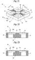
- Figure 21 is an external perspective view
- Figure 22 is a cross-sectional view observed from the arrow direction along the line A-A shown in Figure 21
- Figure 23 is a cross-sectional view observed from the arrowdirection along the line B-B shown in Figure 21.
- the semiconductor acceleration sensor 20 includes a pedestal 21 having a rectangular frame shape and is constituted of a silicon substrate 22 mounted on one opening plane of the pedestal 21.
- a diaphragm 23 of thin film having a cross shape on the upper surface of each of the diaphragmpieces 23a to 23d, there is formed a piezo resistor 26.
- a thick film section 24 On one surface side of the center of the diaphragm 23 in the crossing section of the diaphragm pieces 23a to 23d, there is formed a thick film section 24; on the surface of the thick film section 24, there is mounted a plumb bob 25 having a rectangular solid shape made of, for example, glass.
- an acceleration sensor when an acceleration sensor is arranged with the longitudinal direction of a vehicle corresponding to the X axis, the lateral direction to the Y axis and the vertical direction to the Z axis, a maximum acceleration of about 500 G is sensed in the X-axis direction and on the other hand, an acceleration of about several G at most is sensed in the Y-axis direction. Accordingly, a semiconductor acceleration sensor having a different sensitivity is required depending on the direction of acceleration.
- the acceleration sensitivity is approximately identical in the X axis, Y axis and Z axis directions.
- an object of the present invention is to provide a semiconductor acceleration sensor capable of sensing accelerations in two directions parallel to the surface of a diaphragm and orthogonal to each other with respective proper sensitivities.
- the present invention proposes a semiconductor acceleration sensor comprising: a silicon wafer having a diaphragm formed within a wafer outer-circumferential frame section; a pedestal securing the wafer outer-circumferential frame section; a plumb bob disposed in the center of one surface of the diaphragm; and a plurality of beams extending, respectively, from the center of surface of the diaphragm to the wafer outer-circumferential frame section along X axis and Y axis directions parallel to the surface of the diaphragm and orthogonal to each other, wherein the areas of cross section of the plurality of beams orthogonal to each axis at a predetermined position are set according to a maximum value of respective accelerations in the X axis and Y axis directions.
- the semiconductor acceleration sensor having the above described configuration, there are provided the plurality of beams extending, respectively, from the center of surface of the diaphragm to the wafer outer-circumferential frame section along the X axis and Y axis directions parallel to the surface of the diaphragm and orthogonal to each other, and the areas of cross section of the beams orthogonal to each axis at the predetermined position are set according to the maximum value of respective accelerations in the X axis and Y axis directions.
- the diaphragm is distorted in a direction of the force working, but the displacement is inversely proportional to the cross section area of the diaphragm. Accordingly, when accelerations having the same amplitude are exerted, respectively, in the X axis and Y axis directions, each of the beams are displaced in inverse proportion to the maximum value of acceleration in each axis.
- the present invention proposes the semiconductor acceleration sensor having the above described configuration, wherein in each of the beam disposed along the X axis direction and the beam disposed along the Y axis direction, the cross section area at two points symmetrical around the center is identical.
- the cross section area at two points symmetrical around the center is identical.
- the diaphragm is distorted in a direction of the force working, but the displacement is inversely proportional to the cross section area of the diaphragm. Accordingly, each of the beams are displaced symmetrically around the center.
- the present invention proposes the semiconductor acceleration sensor having the above described configuration, wherein in the beam disposed along the X axis direction and/or the beam disposed along the Y axis direction, the cross section area increases in a direction from the center to the wafer outer-circumferential frame section.
- the cross section area of at least one of the beam disposed along the X axis direction and the beam disposed along the Y axis direction increases in a direction from the center to the wafer outer-circumferential frame section.
- the diaphragm is distorted in a direction of the force working, but the displacement is inversely proportional to the cross section area of the diaphragm. Accordingly, the nearer the center, the larger the displacement of each of the beams.
- the present invention proposes the semiconductor acceleration sensor having the above described configuration, wherein to allow sensing of respective accelerations in the X axis and Y axis directions and a Z axis direction orthogonal to the surface of the diaphragm, a diffused resistor is arranged in each of the plurality of beams and at the same time, on the wafer outer-circumferential frame section corresponding to each of the plurality of beams, there is provided an connection electrode connected to the diffused resistor.
- the diffused resistor is arranged along each of the plurality of beams, and these diffused resistors are each connected to the electrode disposed on the wafer outer-circumferential frame section. Accordingly, an external circuit can be connected to the diffused resistor via the electrode, and the resistance value of the diffused resistor varies in association with displacement of the diaphragm.
- the present invention proposes the semiconductor acceleration sensor having the above described configuration, wherein the diaphragm is a silicon piezo diaphragm.
- the resistance value of the piezo resistor varies in association with displacement of the diaphragm.
- the present invention proposes the semiconductor acceleration sensor having the above described configuration, wherein in one surface side and/or the other surface side of the diaphragm, there is provided a protrusion secured to a position spaced with a predetermined gap from the surface of the center of the diaphragm and/or from the surface of the plumb bob corresponding to the center, and protruding opposite the center.
- the semiconductor acceleration sensor having the above described configuration, when force of a predetermined value or more is exerted by an acceleration generated in a direction orthogonal to the surface of the diaphragm, the diaphragm is distorted and stretched in a direction of the force working. However, the displacement is limited by the protrusion, so the diaphragm cannot be stretched to a maximum. Accordingly, when an excessive acceleration is generated in a direction orthogonal to the surface of the diaphragm, also, the position of the plumb bob changes with the tip end of the protrusion acting as a supporting point, so an acceleration in a direction parallel to the surface of the diaphragm can be sensed.
- the present invention proposes the semiconductor acceleration sensor having the above described configuration, wherein the protrusion is secured and supported to the wafer outer-circumferential frame section and/or the pedestal and disposed at a position spaced with a predetermined gap from the center of the other surface of the diaphragm so as to protrude opposite the center of the other surface of the diaphragm.
- the semiconductor acceleration sensor having the above described configuration, when force of a predetermined value or more is exerted on the other surface side of the diaphragm by an acceleration generated in a direction orthogonal to the surface of the diaphragm, the diaphragm is distorted and stretched in a direction of the force working. However, the displacement is limited by the protrusion, so the diaphragm cannot be stretched to a maximum. Accordingly, when force of the predetermined value or more is exerted on the other surface side of the diaphragm, also, the position of the plumb bob changes with the tip end of the protrusion acting as a supporting point, so an acceleration in a direction parallel to the surface of the diaphragm can be sensed.
- the present invention proposes the semiconductor acceleration sensor having the above described configuration, wherein the protrusion is joined and supported to the wa f er outer-circumferential frame section and/or the pedestal and disposed at a position spaced with a predetermined gap from the center of the plumb bob so as to protrude opposite the surface of the plumb bob.
- the semiconductor acceleration sensor having the above described configuration, when force of a predetermined value or more is exerted on one surface side of the diaphragm by an acceleration generated in a direction orthogonal to the surface of the diaphragm, the diaphragm is distorted and stretched in a direction of the force working. However, the displacement is limited by the protrusion, so the diaphragm cannot be stretched to a maximum. Accordingly, when force of the predetermined value or more is exerted on the one surface side of the diaphragm, also, the position of the plumb bob changes with the tip end of the protrusion acting as a supporting point, so an acceleration in a direction parallel to the surface of the diaphragm can be sensed.
- the present invention proposes the semiconductor acceleration sensor having the above described configuration, wherein the tip end of the protrusion corresponding to the surface of the center of the diaphragm and/or to the surface of the plumb bob corresponding to the center has a cone-shaped tip end configuration.
- the semiconductor acceleration sensor having the above described configuration, when force of a predetermined value or more is exerted by an acceleration generated in a direction orthogonal to the surface of the diaphragm, the diaphragm is distorted and stretched in a direction of the force working. However, the displacement is supported and limited by the cone-shaped tip end of the protrusion, so the diaphragm cannot be stretched to a maximum. At the same time, when an excessive acceleration is generated in a direction orthogonal to the surface of the diaphragm, also, the position of the plumb bob changes with the tip end of the protrusion acting as a supporting point, so an acceleration in a direction parallel to the surface of the diaphragm can be sensed.
- the area of cross section orthogonal to the X axis of the diaphragm pieces being the beams disposed on a single line along the X axis direction and the area of cross section orthogonal to the Y axis of the diaphragm pieces being the beams disposed on a single line along the Y axis direction are each symmetrical around the central of the diaphragm and set according to a maximum value of respective accelerations in the X axis or Y axis directions, the X axis and Y axis being parallel to the surface of the diaphragm and orthogonal to each other.
- FIG 1 is an external perspective view showing a semiconductor acceleration sensor according to a first embodiment of the present invention.
- the semiconductor acceleration sensor 10 is constituted of a pedestal 11 and a silicon substrate 12.
- the pedestal 11 has a rectangular frame shape.
- the silicon substrate 12 silicon wafer
- the silicon substrate 12 In the opening of the pedestal 11, there is provided the silicon substrate 12; in the center within a wafer outer-circumferential frame section 12a of the silicon substrate 12, there is formed a diaphragm 13 of thin film having a cross shape.
- the diaphragm 13 is constituted of diaphragm pieces 13a to 13d being four beams each extending from the center of the diaphragm surface to the wafer outer-circumferential frame section 12a along an X axis direction and a Y axis direction orthogonal to each other; on the upper surface of the diaphragm pieces, there are formed piezo resistors (diffused resistors) Rx1 to Rx4, Ry1 to Ry4, Rz1 to Rz4.
- one diaphragm piece 13a of the diaphragm pieces 13a and 13b disposed on a single line there are formed the piezo resistors Rx1, Rx2, Rz1 and Rz2; in the other diaphragm piece 13b, there are formed the piezo resistors Rx3, Rx4, Rz3 and Rz4.
- the piezo resistors Ry1 and Ry2 in the other diaphragm piece 13d, there are formed the piezo resistors Ry3 and Ry4.
- the piezo resistors Rx1 to Rx4, Ry1 to Ry4, and Rz1 to Rz4 are connected to a connection electrode 121 disposed on the surface of the outer-circumferential section of the silicon substrate 12 so that they can constitute a resistor bridge circuit for sensing accelerations in the directions of the X axis, Y axis and Z axis orthogonal to each other.
- a thick film section 14 On one surface side of the center of the diaphragm 13 in the crossing section of the diaphragm pieces 13a to 13d, there is formed a thick film section 14; on the surface of the thick film section 14, there is mounted a plumb bob 15 having a rectangular solid shape made of, for example, glass.
- FIG. 3 When the semiconductor acceleration sensor 10 having the above described configuration is used, three resistor bridge circuits are constructed as shown in Figures 3 to 5. More specifically, in a bridge circuit for sensing an acceleration in the X axis direction, as shown in Figure 3, the positive electrode of a DC power supply 32A is connected to a connection point between one end of a piezo resistor Rx1 and one end of a piezo resistor Rx2, and the negative electrode of the direct current power source 32A is connected to a connection point between one end of a piezo resistor Rx3 and one end of a piezo resistor Rx4.
- one end of a voltage detector 31A is connected to a connection point between the other end of the piezo resistor Rx1 and the other end of the piezo resistor Rx4, and the other end of the voltage detector 31A is connected to a connection point between the other end of the piezo resistor Rx2 and the other end of the piezo resistor Rx3.
- the positive electrode of a DC power supply 32B is connected to a connection point between one end of a piezo resistor Ry1 and one end of a piezo resistor Ry2, and the negative electrode of the DC power supply 32B is connected to a connection point between one end of a piezo resistor Ry3 and one end of a piezo resistor Ry4.
- one end of a voltage detector 31B is connected to a connection point between the other end of the piezo resistor Ry1 and the other end of the piezo resistor Ry4, and the other end of the voltage detector 31B is connected to a connection point between the other end of the piezo resistor Ry2 and the other end of the piezo resistor Ry3.
- the positive electrode of a DC power supply 32C is connected to a connection point between one end of a piezo resistor Rz1 and one end of a piezo resistor Rz2, and the negative electrode of the DC power supply 32C is connected to a connection point between one end of a piezo resistor Rz3 and one end of a piezo resistor Rz4.
- one end of a voltage detector 31C is connected to a connection point between the other end of the piezo resistor Rz1 and the other end of the piezo resistor Rz3, and the other end of the voltage detector 31C is connected to a connection point between the other end of the piezo resistor Rz2 and the other end of the piezo resistor Rz4.
- Figure 6 is a cross-sectional view observed from the arrow direction along the lineC-C shown in Figure 1;
- Figure 7 is a cross-sectionalviewobserved from the arrow direction along the line D-D shown in Figure 1;
- Figure 8 is a cross-sectional view observed from the arrow direction along the line C1-C1 shown in Figure 6;
- Figure 9 is a cross-sectional view observed from the arrow direction along the line D1-D1 shown in Figure 7.
- the areas of cross section orthogonal to each axis are uniform and set according to a maximum value of acceleration, respectively, in the X axis direction or the Y axis direction.
- accelerations are sensed with the longitudinal direction of a vehicle corresponding to the X axis and the lateral direction to the Y axis, and the cross section area of the diaphragm pieces 13a and 13b along the X axis direction is set larger than that of the diaphragm pieces 13c and 13d along the Y axis direction.
- the diaphragm 13 When force by acceleration is exerted, the diaphragm 13 distorts in a direction of the force working. However, its displacement is in inverse proportion to the cross section area of the diaphragm pieces 13a to 13d. Consequently, when an acceleration of the same amplitude is applied in each of the X axis direction and Y axis direction, the diaphragm pieces 13a to 13d are displaced in inverse proportion to the maximum value of acceleration in each axis. Also, the cross section areas of each of the diaphragm pieces 13a to 13d are uniform and symmetrical around the center of the diaphragm 13, so the diaphragm pieces are displaced symmetrically around the center.
- each said diaphragm pieces 13a to 13d are 70 [ ⁇ m] and 20 [ ⁇ m], respectively.
- experimental results of accelerations sensed by the diaphragm 13 is shown in Figure 11.
- the applied acceleration is 0 to 100 [G]
- the difference between the sensed accelerations in the directions of the X axis and Y axis and the applied acceleration was 1 % or less
- the difference between the sensed acceleration in the Z axis direction and the applied acceleration was 3 % or less.
- the diaphragm 13 in which the cross section areas of each said diaphragm pieces 13a to 13d are uniform. However, it is sufficient that the cross section areas of each said diaphragm pieces 13a to 13d are symmetrical around the center of the diaphragm 13. As shown in Figures 14 to 17, in the diaphragm pieces 13a and 13b disposed on a single line along the X axis direction, when the cross section area increases in a direction from the center of the diaphragm 13 to the wafer outer-circumferential frame section 12a, then the nearer the center of the diaphragm, the larger the displacement of the diaphragm pieces 13a and 13b. Particularly, the cross section area is varied stepwise between the position of the piezo resistors Rx1 to Rx4 formed and the other position, so the variation in resistance value of the piezo resistors Rx1 to Rx4 is significant.
- the semiconductor acceleration sensor 10 having the above described configuration, with respect to the diaphragm pieces 13a and 13b disposed on a single line along the X axis direction and the diaphragm pieces 13c and 13d disposed on a single line along the Y axis direction, the X axis and Y axis being parallel to the surface of the diaphragm and orthogonal to each other, the areas of cross section orthogonal to each axis are symmetrical around the central of the diaphragm 13 and set according to a maximum value of respective accelerations in the X axis or Y axis direction.
- the cross section areas increase in a direction from the center of the diaphragm 13 to the wafer outer-circumferential frame section 12a, so the nearer the center of the diaphragm 13, the larger the displacement of the diaphragm pieces 13a to 13d and at the same time, the more significant the variation in the piezo resistors Rx1 to Rx4, Ry1 to Ry4, Rz1 to Rz4, thus allowing sensing of accelerations with higher accuracy.
- Figure 18 is an exploded perspective view showing a semiconductor acceleration sensor according to a second embodiment of the present invention
- Figure 19 is a side cross sectional view thereof
- Figure 20 is a view for explaining the operation thereof.
- the same reference characters denote constituent parts corresponding to the first embodiment described above, and an explanation thereof is omitted.
- the difference between the second embodiment and the first embodiment lies in that the second embodiment includes in addition to the configuration of the first embodiment, support bodies 16 and 50 having protrusions disposed both in one side where the plumb bob 15 of the diaphragm 13 is present and the other side where the plumb bob 15 of the diaphragm 13 is not present.
- the semiconductor acceleration sensor 10B is constituted of a pedestal 11, a silicon substrate 12 and the support bodies 16 and 50. To the outer-circumferential section of the pedestal 11, there is secured an outer frame section 161 of the support body 16.
- the support body 16 is constituted of the outer frame section 161 having a rectangular frame shape, four supporting columns 162 installed in the four corners of the outer frame section 161, a beam section 163 having a cross shape disposed so as to join the tip ends of each supporting column 162, and a protrusion 164 having a cone shape disposed in the central, crossing part of the beam section 163.
- the outer frame section 161 is fit into the outer-circumferential section of the pedestal 11 to be secured, so that the protrusion 164 is positioned in the other surface side of the diaphragm 13, i.e., in the side where the plumb bob 15 is not present.
- a setting is made such that the tip end 164a of the protrusion 164 is positioned at a distance d1 from the surface of the diaphragm 13.
- the distance d1 is set to a value by which the displacement of each of the diaphragm pieces 13c and 13d can be limited by the protrusion 164 so that the diaphragm pieces are not stretched excessively even when an acceleration is generated in a direction orthogonal to the surface of the diaphragm 13 and force of a predetermined value or more caused by the acceleration is exerted on the other surface side of the diaphragm 13, i.e., on the side where the plumb bob 15 is not present.
- the support body 50 is constituted of an outer frame section 501 having a rectangular frame shape, four supporting columns 502 installed in the four corners of the outer frame section 501, a beam section 503 having a cross shape disposed so as to join the tip ends of each supporting column 502, and a protrusion 504 having a cone shape disposed in the central, crossing part of the beam section 503.
- the outer frame section 501 is secured to the outer-circumferential section of the pedestal 11 so that the protrusion 504 is positioned in the bottom surface side of the plumb bob 15.
- a setting is made such that the tip end 504a of the protrusion 504 is positioned at a distance dl from the bottom surface side of the plumb bob 15.
- the distance dl is set to a value by which the displacement of each of the diaphragm pieces 13c and 13d can be limited by the protrusion 504 so that the diaphragm pieces are not stretched excessively even when an acceleration is generated in a direction orthogonal to the surface of the diaphragm 13 and force of a predetermined value or more caused by the acceleration is exerted on one surface side of the diaphragm 13, i.e., on the side where the plumb bob 15 is present.
- an acceleration sensor with a plurality of beams whose cross section area orthogonal, respectively, to one of the X axis and Y axis directions parallel to the surface of the diaphragm and orthogonal to each other are set according to a maximum value of acceleration in the X axis or Y axis direction, accelerations in the X axis and Y axis directions can be sensed with respective proper sensitivities. Accordingly, the sensor is applicable to a vehicle for which different sensitivity between the longitudinal direction and lateral direction of the vehicle is required.
Landscapes
- Physics & Mathematics (AREA)
- General Physics & Mathematics (AREA)
- Pressure Sensors (AREA)
Abstract
Description
- The present invention relates to a semiconductor acceleration sensor, and more particularly to a semiconductor acceleration sensor that senses accelerations in directions orthogonal to each other with respective proper sensitivities.
- There has hitherto been used semiconductor acceleration sensors disposed in a vehicle or tire of an automobile for performing vehicle posture control or sensing a distortion of the tire.
- One example of this sort of semiconductor acceleration sensor will be described with reference to Figures 21 to 23. Figure 21 is an external perspective view; Figure 22 is a cross-sectional view observed from the arrow direction along the line A-A shown in Figure 21; Figure 23 is a cross-sectional view observed from the arrowdirection along the line B-B shown in Figure 21. As shown in Figure 21, the
semiconductor acceleration sensor 20 includes apedestal 21 having a rectangular frame shape and is constituted of asilicon substrate 22 mounted on one opening plane of thepedestal 21. - Also, in the center of the
silicon substrate 22 corresponding to the opening of thepedestal 21, there is formed a diaphragm 23 of thin film having a cross shape; on the upper surface of each of thediaphragmpieces 23a to 23d, there is formed apiezo resistor 26. Further, on one surface side of the center of the diaphragm 23 in the crossing section of thediaphragm pieces 23a to 23d, there is formed athick film section 24; on the surface of thethick film section 24, there is mounted aplumb bob 25 having a rectangular solid shape made of, for example, glass. - In the
semiconductor acceleration sensor 20 having the above described configuration, when force generated in association with acceleration is exerted on theplumb bob 25, distortion occurs in each of thediaphragm pieces 23a to 23d, whereby the resistance value of thepiezo resistor 26 varies. Accordingly, with the resistor bridge circuit formed with thepiezo resistor 26 arranged in each of thepredetermined diaphragm pieces 23a to 23d, accelerations can be sensed in predetermined directions, e.g., in X axis, Y axis and Z axis directions orthogonal to each other. - As an example of the semiconductor acceleration sensor described above, there has been known semiconductor acceleration sensors disclosed in
Japanese Patent Publication Nos. H8-75775 2000-28633
Japanese Patent Publication No. H8-75775
Japanese Patent Publication No. 2000-28633 - For example, when an acceleration sensor is arranged with the longitudinal direction of a vehicle corresponding to the X axis, the lateral direction to the Y axis and the vertical direction to the Z axis, a maximum acceleration of about 500 G is sensed in the X-axis direction and on the other hand, an acceleration of about several G at most is sensed in the Y-axis direction. Accordingly, a semiconductor acceleration sensor having a different sensitivity is required depending on the direction of acceleration.
- However, in the conventional semiconductor acceleration sensor described above, the acceleration sensitivity is approximately identical in the X axis, Y axis and Z axis directions. Thus, it is possible that when adjustment is made to a maximum value of acceleration in the X axis direction, a minor variation in acceleration in the Y axis cannot be sensed; when adjustment is made to a maximum value of acceleration in the Y axis direction, an acceleration of a predetermined value or more in the X axis cannot be sensed.
- To address the above problem, an object of the present invention is to provide a semiconductor acceleration sensor capable of sensing accelerations in two directions parallel to the surface of a diaphragm and orthogonal to each other with respective proper sensitivities.
- To achieve the above object, the present invention proposes a semiconductor acceleration sensor comprising: a silicon wafer having a diaphragm formed within a wafer outer-circumferential frame section; a pedestal securing the wafer outer-circumferential frame section; a plumb bob disposed in the center of one surface of the diaphragm; and a plurality of beams extending, respectively, from the center of surface of the diaphragm to the wafer outer-circumferential frame section along X axis and Y axis directions parallel to the surface of the diaphragm and orthogonal to each other, wherein the areas of cross section of the plurality of beams orthogonal to each axis at a predetermined position are set according to a maximum value of respective accelerations in the X axis and Y axis directions.
- According to the semiconductor acceleration sensor having the above described configuration, there are provided the plurality of beams extending, respectively, from the center of surface of the diaphragm to the wafer outer-circumferential frame section along the X axis and Y axis directions parallel to the surface of the diaphragm and orthogonal to each other, and the areas of cross section of the beams orthogonal to each axis at the predetermined position are set according to the maximum value of respective accelerations in the X axis and Y axis directions. Here, when force is exerted by acceleration, the diaphragm is distorted in a direction of the force working, but the displacement is inversely proportional to the cross section area of the diaphragm. Accordingly, when accelerations having the same amplitude are exerted, respectively, in the X axis and Y axis directions, each of the beams are displaced in inverse proportion to the maximum value of acceleration in each axis.
- Also, the present invention proposes the semiconductor acceleration sensor having the above described configuration, wherein in each of the beam disposed along the X axis direction and the beam disposed along the Y axis direction, the cross section area at two points symmetrical around the center is identical.
- According to the semiconductor acceleration sensor having the above described conf iguration, in each of the beam of the X axis direction and the beam of the Y axis direction, the cross section area at two points symmetrical around the center is identical. Here, when force by acceleration is exerted, the diaphragm is distorted in a direction of the force working, but the displacement is inversely proportional to the cross section area of the diaphragm. Accordingly, each of the beams are displaced symmetrically around the center.
- Also, the present invention proposes the semiconductor acceleration sensor having the above described configuration, wherein in the beam disposed along the X axis direction and/or the beam disposed along the Y axis direction, the cross section area increases in a direction from the center to the wafer outer-circumferential frame section.
- According to the semiconductor acceleration sensor having the above described configuration, the cross section area of at least one of the beam disposed along the X axis direction and the beam disposed along the Y axis direction increases in a direction from the center to the wafer outer-circumferential frame section. Here, when force by acceleration is exerted, the diaphragm is distorted in a direction of the force working, but the displacement is inversely proportional to the cross section area of the diaphragm. Accordingly, the nearer the center, the larger the displacement of each of the beams.
- Also, the present invention proposes the semiconductor acceleration sensor having the above described configuration, wherein to allow sensing of respective accelerations in the X axis and Y axis directions and a Z axis direction orthogonal to the surface of the diaphragm, a diffused resistor is arranged in each of the plurality of beams and at the same time, on the wafer outer-circumferential frame section corresponding to each of the plurality of beams, there is provided an connection electrode connected to the diffused resistor.
- According to the semiconductor acceleration sensor having the above described configuration, to allow sensing of respective accelerations in the X axis and Y axis directions and the Z axis direction orthogonal to the surface of the diaphragm, the diffused resistor is arranged along each of the plurality of beams, and these diffused resistors are each connected to the electrode disposed on the wafer outer-circumferential frame section. Accordingly, an external circuit can be connected to the diffused resistor via the electrode, and the resistance value of the diffused resistor varies in association with displacement of the diaphragm.
- Also, the present invention proposes the semiconductor acceleration sensor having the above described configuration, wherein the diaphragm is a silicon piezo diaphragm.
- According to the semiconductor acceleration sensor having the above described configuration, the resistance value of the piezo resistor varies in association with displacement of the diaphragm.
- Also, the present invention proposes the semiconductor acceleration sensor having the above described configuration, wherein in one surface side and/or the other surface side of the diaphragm, there is provided a protrusion secured to a position spaced with a predetermined gap from the surface of the center of the diaphragm and/or from the surface of the plumb bob corresponding to the center, and protruding opposite the center.
- According to the semiconductor acceleration sensor having the above described configuration, when force of a predetermined value or more is exerted by an acceleration generated in a direction orthogonal to the surface of the diaphragm, the diaphragm is distorted and stretched in a direction of the force working. However, the displacement is limited by the protrusion, so the diaphragm cannot be stretched to a maximum. Accordingly, when an excessive acceleration is generated in a direction orthogonal to the surface of the diaphragm, also, the position of the plumb bob changes with the tip end of the protrusion acting as a supporting point, so an acceleration in a direction parallel to the surface of the diaphragm can be sensed.
- Also, the present invention proposes the semiconductor acceleration sensor having the above described configuration, wherein the protrusion is secured and supported to the wafer outer-circumferential frame section and/or the pedestal and disposed at a position spaced with a predetermined gap from the center of the other surface of the diaphragm so as to protrude opposite the center of the other surface of the diaphragm.
- According to the semiconductor acceleration sensor having the above described configuration, when force of a predetermined value or more is exerted on the other surface side of the diaphragm by an acceleration generated in a direction orthogonal to the surface of the diaphragm, the diaphragm is distorted and stretched in a direction of the force working. However, the displacement is limited by the protrusion, so the diaphragm cannot be stretched to a maximum. Accordingly, when force of the predetermined value or more is exerted on the other surface side of the diaphragm, also, the position of the plumb bob changes with the tip end of the protrusion acting as a supporting point, so an acceleration in a direction parallel to the surface of the diaphragm can be sensed.
- Also, the present invention proposes the semiconductor acceleration sensor having the above described configuration, wherein the protrusion is joined and supported to the wa f er outer-circumferential frame section and/or the pedestal and disposed at a position spaced with a predetermined gap from the center of the plumb bob so as to protrude opposite the surface of the plumb bob.
- According to the semiconductor acceleration sensor having the above described configuration, when force of a predetermined value or more is exerted on one surface side of the diaphragm by an acceleration generated in a direction orthogonal to the surface of the diaphragm, the diaphragm is distorted and stretched in a direction of the force working. However, the displacement is limited by the protrusion, so the diaphragm cannot be stretched to a maximum. Accordingly, when force of the predetermined value or more is exerted on the one surface side of the diaphragm, also, the position of the plumb bob changes with the tip end of the protrusion acting as a supporting point, so an acceleration in a direction parallel to the surface of the diaphragm can be sensed.
- Also, the present invention proposes the semiconductor acceleration sensor having the above described configuration, wherein the tip end of the protrusion corresponding to the surface of the center of the diaphragm and/or to the surface of the plumb bob corresponding to the center has a cone-shaped tip end configuration.
- According to the semiconductor acceleration sensor having the above described configuration, when force of a predetermined value or more is exerted by an acceleration generated in a direction orthogonal to the surface of the diaphragm, the diaphragm is distorted and stretched in a direction of the force working. However, the displacement is supported and limited by the cone-shaped tip end of the protrusion, so the diaphragm cannot be stretched to a maximum. At the same time, when an excessive acceleration is generated in a direction orthogonal to the surface of the diaphragm, also, the position of the plumb bob changes with the tip end of the protrusion acting as a supporting point, so an acceleration in a direction parallel to the surface of the diaphragm can be sensed.
- According to the present invention, the area of cross section orthogonal to the X axis of the diaphragm pieces being the beams disposed on a single line along the X axis direction and the area of cross section orthogonal to the Y axis of the diaphragm pieces being the beams disposed on a single line along the Y axis direction are each symmetrical around the central of the diaphragm and set according to a maximum value of respective accelerations in the X axis or Y axis directions, the X axis and Y axis being parallel to the surface of the diaphragm and orthogonal to each other. Consequently, displacement occurs in inverse proportion to the maximum value of acceleration in each axis, and accelerations in two directions parallel to the surface of the diaphragm and orthogonal to each other can be sensed with respective proper sensitivities. Also, the cross section area increases in a direction from the center of the diaphragm to the wafer outer-circumferential frame section, so the nearer the center of the diaphragm, the larger the displacement of the diaphragm piece and at the same time, the more significant the variation in piezo resistor, thus allowing sensing of accelerations with higher accuracy.
- Further, when an excessive acceleration is generated in a direction orthogonal to the surface of the diaphragm, the position of the plumb bob changes with the tip end of the protrusion acting as a supporting point. Accordingly, a highly excellent effect is achieved that even when the cross section area of the diaphragm piece is reduced to vary the sensitivity, accelerations in two directions parallel to the surface of the diaphragm and orthogonal to each other can be effectively sensed.
- These and other objects, features and advantages according to the present invention will be evident from the following description and the accompanying drawings.
-
- Figure 1 is an external perspective view showing a semiconductor acceleration sensor according to a first embodiment of the present invention;
- Figure 2 is a configuration diagram showing an electrical circuit of the semiconductor acceleration sensor according to the first embodiment of the present invention;
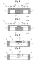
- Figure 3 is a view showing a bridge circuit sensing an acceleration in an X axis direction using the semiconductor acceleration sensor according to the first embodiment of the present invention;
- Figure 4 is a view showing a bridge circuit sensing an acceleration in a Y axis direction using the semiconductor acceleration sensor according to the first embodiment of the present invention;
- Figure 5 is a view showing a bridge circuit sensing an acceleration in a Z axis direction using the semiconductor acceleration sensor according to the first embodiment of the present invention;
- Figure 6 is a cross-sectional viewobserved fromthe arrowdirection along the line C-C shown in Figure 1;
- Figure 7 is a cross-sectional view observed fromthe arrowdirection along the line D-D shown in Figure 1;
- Figure 8 is a cross-sectionalviewobserved fromthe arrowdirection along the line C1-C1 shown in Figure 6;
- Figure 9 is a cross-sectional view observed fromthe arrowdirection along the line D1-D1 shown in Figure 7;
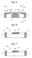
- Figure 10 is a view showing experimental results of accelerations sensed by a diaphragm according to the first embodiment of the present invention;
- Figure 11 is a view showing experimental results of accelerations sensed by the diaphragm according to the first embodiment of the present invention;
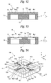
- Figure 12 is a view for explaining the operation of the semiconductor acceleration sensor according to the first embodiment of the present invention;
- Figure 13 is a view for explaining the operation of the semiconductor acceleration sensor according to the first embodiment of the present invention;
- Figure 14 is an external perspective view showing another semiconductor acceleration sensor according to the first embodiment of the present invention;
- Figure 15 is a cross-sectional view observed from the arrow direction along the line E-E shown in Figure 14;
- Figure 16 is a cross-sectional view observed from the arrow direction along the line E1-E1 shown in Figure 14;
- Figure 17 is a cross-sectional view observed from the arrow direction along the line E2-E2 shown in Figure 14;
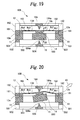
- Figure 18 is an exploded perspective view showing a semiconductor acceleration sensor according to a second embodiment of the present invention;
- Figure 19 is a side cross sectional view showing the semiconductor acceleration sensor according to the second embodiment of the present invention;
- Figure 20 is a view for explaining the operation of the semiconductor acceleration sensor according to the second embodiment of the present invention;
- Figure 21 is an external perspective view showing a semiconductor acceleration sensor being a conventional example;
- Figure 22 is a cross-sectional view observed from the arrow direction along the line A-A shown in Figure 21; and
- Figure 23 is a cross-sectional view observed from the arrow direction along the line B-B shown in Figure 21.
- 10, 10A, 10B ... semiconductor acceleration sensor, 11 ... pedestal, 12 ... silicon substrate, 12a ... wafer outer-circumferential section frame, 121 ... electrode, 13 ... diaphragm, 13a to 13d ... diaphragm piece, 14 ... thick film section, 15 ... plumb bob, 16 ... support body, 161 ... outer frame section, 162 ... supporting column, 163 ... beam section, 164 ... protrusion, 164a ... tip end, 31A to 31C ... voltage detector, 32A to 32C ... DC power supply, 50 ... support body, 501 ... outer frame section, 502 ... supporting column, 503 ... beam section, 504 ... protrusion, 504a ... tip end, dl ... distance, Rx1 to Rx4, Ry1 to Ry4, Rz1 to Rz4 ... piezo resistor (diffused resistor)
- An embodiment of the present invention will be described with reference to the drawings.
- Figure 1 is an external perspective view showing a semiconductor acceleration sensor according to a first embodiment of the present invention. Referring to Figure 1, the
semiconductor acceleration sensor 10 is constituted of apedestal 11 and asilicon substrate 12. Thepedestal 11 has a rectangular frame shape. On one open surface of thepedestal 11, there is mounted the silicon substrate 12 (silicon wafer) . - In the opening of the
pedestal 11, there is provided thesilicon substrate 12; in the center within a wafer outer-circumferential frame section 12a of thesilicon substrate 12, there is formed adiaphragm 13 of thin film having a cross shape. Thediaphragm 13 is constituted ofdiaphragm pieces 13a to 13d being four beams each extending from the center of the diaphragm surface to the wafer outer-circumferential frame section 12a along an X axis direction and a Y axis direction orthogonal to each other; on the upper surface of the diaphragm pieces, there are formed piezo resistors (diffused resistors) Rx1 to Rx4, Ry1 to Ry4, Rz1 to Rz4. - Specifically, in one
diaphragm piece 13a of thediaphragm pieces other diaphragm piece 13b, there are formed the piezo resistors Rx3, Rx4, Rz3 and Rz4. Also, in onediaphragm piece 13c of thediaphragm pieces diaphragm pieces other diaphragm piece 13d, there are formed the piezo resistors Ry3 and Ry4. - Also, the piezo resistors Rx1 to Rx4, Ry1 to Ry4, and Rz1 to Rz4 are connected to a
connection electrode 121 disposed on the surface of the outer-circumferential section of thesilicon substrate 12 so that they can constitute a resistor bridge circuit for sensing accelerations in the directions of the X axis, Y axis and Z axis orthogonal to each other. - Further, on one surface side of the center of the
diaphragm 13 in the crossing section of thediaphragm pieces 13a to 13d, there is formed athick film section 14; on the surface of thethick film section 14, there is mounted a plumbbob 15 having a rectangular solid shape made of, for example, glass. - When the
semiconductor acceleration sensor 10 having the above described configuration is used, three resistor bridge circuits are constructed as shown in Figures 3 to 5. More specifically, in a bridge circuit for sensing an acceleration in the X axis direction, as shown in Figure 3, the positive electrode of aDC power supply 32A is connected to a connection point between one end of a piezo resistor Rx1 and one end of a piezo resistor Rx2, and the negative electrode of the directcurrent power source 32A is connected to a connection point between one end of a piezo resistor Rx3 and one end of a piezo resistor Rx4. Further, one end of avoltage detector 31A is connected to a connection point between the other end of the piezo resistor Rx1 and the other end of the piezo resistor Rx4, and the other end of thevoltage detector 31A is connected to a connection point between the other end of the piezo resistor Rx2 and the other end of the piezo resistor Rx3. - Also, in a bridge circuit for sensing an acceleration in the Y axis direction, as shown in Figure 4, the positive electrode of a
DC power supply 32B is connected to a connection point between one end of a piezo resistor Ry1 and one end of a piezo resistor Ry2, and the negative electrode of theDC power supply 32B is connected to a connection point between one end of a piezo resistor Ry3 and one end of a piezo resistor Ry4. Further, one end of avoltage detector 31B is connected to a connection point between the other end of the piezo resistor Ry1 and the other end of the piezo resistor Ry4, and the other end of thevoltage detector 31B is connected to a connection point between the other end of the piezo resistor Ry2 and the other end of the piezo resistor Ry3. - Also, in a bridge circuit for sensing an acceleration in the Z axis direction, as shown in Figure 5, the positive electrode of a
DC power supply 32C is connected to a connection point between one end of a piezo resistor Rz1 and one end of a piezo resistor Rz2, and the negative electrode of theDC power supply 32C is connected to a connection point between one end of a piezo resistor Rz3 and one end of a piezo resistor Rz4. Further, one end of avoltage detector 31C is connected to a connection point between the other end of the piezo resistor Rz1 and the other end of the piezo resistor Rz3, and the other end of thevoltage detector 31C is connected to a connection point between the other end of the piezo resistor Rz2 and the other end of the piezo resistor Rz4. - When force generated in association with acceleration applied to the
sensor 10 is exerted on the plumbbob 15, distortion occurs in each of thediaphragm pieces 13a to 13d, whereby the value of the piezo resistors Rx1 to Rx4, Ry1 to Ry4 and Rz1 to Rz4 varies. Accordingly, with the resistor bridge circuit formed with the piezo resistors Rx1 to Rx4, Ry1 to Ry4 and Rz1 to Rz4 disposed in each of thediaphragm pieces 13a to 13d, accelerations are sensed in the directions of the X axis, Y axis and Z axis orthogonal to each other. - There will now be described the configuration of the
diaphragm pieces 13a to 13d by which the present invention is characterized. Figure 6 is a cross-sectional view observed from the arrow direction along the lineC-C shown in Figure 1; Figure 7 is a cross-sectionalviewobserved from the arrow direction along the line D-D shown in Figure 1; Figure 8 is a cross-sectional view observed from the arrow direction along the line C1-C1 shown in Figure 6; and Figure 9 is a cross-sectional view observed from the arrow direction along the line D1-D1 shown in Figure 7. - In the
diaphragm pieces diaphragm pieces diaphragm pieces diaphragm pieces - When force by acceleration is exerted, the
diaphragm 13 distorts in a direction of the force working. However, its displacement is in inverse proportion to the cross section area of thediaphragm pieces 13a to 13d. Consequently, when an acceleration of the same amplitude is applied in each of the X axis direction and Y axis direction, thediaphragm pieces 13a to 13d are displaced in inverse proportion to the maximum value of acceleration in each axis. Also, the cross section areas of each of thediaphragm pieces 13a to 13d are uniform and symmetrical around the center of thediaphragm 13, so the diaphragm pieces are displaced symmetrically around the center. - Here, as shown in Figures 8 and 9, when the width of the diaphragm piece is W and the thickness is T, experimental results of accelerations sensed by the
diaphragm 13 is shown in Figure 10, where the width and thickness of each saiddiaphragm pieces 13a to 13d are 100 [µm] and 14 [µm], respectively. When the acceleration applied to thediaphragm 13 is 0 to 30 [G], the difference between the sensed acceleration in the directions of the X axis, Y axis and Z axis and the applied acceleration was 1 % or less. - Also, when the width and thickness of each said
diaphragm pieces 13a to 13d are 70 [µm] and 20 [µm], respectively, experimental results of accelerations sensed by thediaphragm 13 is shown in Figure 11. When the applied acceleration is 0 to 100 [G], the difference between the sensed accelerations in the directions of the X axis and Y axis and the applied acceleration was 1 % or less, and the difference between the sensed acceleration in the Z axis direction and the applied acceleration was 3 % or less. - As shown in Figures 12 and 13, when accelerations having the same amplitude are generated in the directions of the X axis and Y axis parallel to the surface of the
diaphragm 13 and orthogonal to each other and force 41 and 42 by the accelerations work, the diaphragm is stretched in the directions of theforce diaphragm pieces force 41 hardly occurs; in contrast, since the cross section area of thediaphragm pieces force 42 occurs. - According to the present embodiment, there is shown the
diaphragm 13 in which the cross section areas of each saiddiaphragm pieces 13a to 13d are uniform. However, it is sufficient that the cross section areas of each saiddiaphragm pieces 13a to 13d are symmetrical around the center of thediaphragm 13. As shown in Figures 14 to 17, in thediaphragm pieces diaphragm 13 to the wafer outer-circumferential frame section 12a, then the nearer the center of the diaphragm, the larger the displacement of thediaphragm pieces - In this manner, according to the
semiconductor acceleration sensor 10 having the above described configuration, with respect to thediaphragm pieces diaphragm pieces diaphragm 13 and set according to a maximum value of respective accelerations in the X axis or Y axis direction. Consequently, displacement occurs in inverse proportion to the maximum value of acceleration in each axis, and accelerations in the two directions parallel to the surface of thediaphragm 13 and orthogonal to each other can be sensed with respective proper sensitivities. Also, the cross section areas increase in a direction from the center of thediaphragm 13 to the wafer outer-circumferential frame section 12a, so the nearer the center of thediaphragm 13, the larger the displacement of thediaphragm pieces 13a to 13d and at the same time, the more significant the variation in the piezo resistors Rx1 to Rx4, Ry1 to Ry4, Rz1 to Rz4, thus allowing sensing of accelerations with higher accuracy. - A second embodiment of the present invention will now be described.
- Figure 18 is an exploded perspective view showing a semiconductor acceleration sensor according to a second embodiment of the present invention; Figure 19 is a side cross sectional view thereof; and Figure 20 is a view for explaining the operation thereof. In the drawings, the same reference characters denote constituent parts corresponding to the first embodiment described above, and an explanation thereof is omitted. The difference between the second embodiment and the first embodiment lies in that the second embodiment includes in addition to the configuration of the first embodiment,
support bodies bob 15 of thediaphragm 13 is present and the other side where the plumbbob 15 of thediaphragm 13 is not present. - Referring to the drawings, the
semiconductor acceleration sensor 10B is constituted of apedestal 11, asilicon substrate 12 and thesupport bodies pedestal 11, there is secured anouter frame section 161 of thesupport body 16. - The
support body 16 is constituted of theouter frame section 161 having a rectangular frame shape, four supportingcolumns 162 installed in the four corners of theouter frame section 161, abeam section 163 having a cross shape disposed so as to join the tip ends of each supportingcolumn 162, and aprotrusion 164 having a cone shape disposed in the central, crossing part of thebeam section 163. - The
outer frame section 161 is fit into the outer-circumferential section of thepedestal 11 to be secured, so that theprotrusion 164 is positioned in the other surface side of thediaphragm 13, i.e., in the side where the plumbbob 15 is not present. Here, a setting is made such that thetip end 164a of theprotrusion 164 is positioned at a distance d1 from the surface of thediaphragm 13. The distance d1 is set to a value by which the displacement of each of thediaphragm pieces protrusion 164 so that the diaphragm pieces are not stretched excessively even when an acceleration is generated in a direction orthogonal to the surface of thediaphragm 13 and force of a predetermined value or more caused by the acceleration is exerted on the other surface side of thediaphragm 13, i.e., on the side where the plumbbob 15 is not present. - The
support body 50 is constituted of anouter frame section 501 having a rectangular frame shape, four supportingcolumns 502 installed in the four corners of theouter frame section 501, abeam section 503 having a cross shape disposed so as to join the tip ends of each supportingcolumn 502, and aprotrusion 504 having a cone shape disposed in the central, crossing part of thebeam section 503. - The
outer frame section 501 is secured to the outer-circumferential section of thepedestal 11 so that theprotrusion 504 is positioned in the bottom surface side of the plumbbob 15. Here, a setting is made such that thetip end 504a of theprotrusion 504 is positioned at a distance dl from the bottom surface side of the plumbbob 15. The distance dl is set to a value by which the displacement of each of thediaphragm pieces protrusion 504 so that the diaphragm pieces are not stretched excessively even when an acceleration is generated in a direction orthogonal to the surface of thediaphragm 13 and force of a predetermined value or more caused by the acceleration is exerted on one surface side of thediaphragm 13, i.e., on the side where the plumbbob 15 is present. - In this manner, according to the
semiconductor acceleration sensor 10B of the second embodiment having the above described configuration, as shown in Figure 20, when an acceleration is applied such thatforce 43 including a force component in a direction orthogonal to the surface of thediaphragm 13 is exerted and force of a predetermined value or more is exerted on the other surface side of thediaphragm 13, thediaphragm 13 is distorted and stretched in a direction of theforce 43 working. However, the displacement is supported and limited by thetip end 164a of theprotrusion 164, so thediaphragm pieces bob 15, also, the displacement is similarly supported and limited by thetip end 504a of theprotrusion 504, so thediaphragm pieces - Accordingly, when an acceleration is generated in a direction orthogonal to the surface of the
diaphragm 13 and force of a predetermined value or more by the acceleration is exerted, the position of the plumbbob 15 changes with thetip end 504a of theprotrusion 504 acting as a supporting point. Thus, even when the cross section area of thediaphragm pieces 13a to 13d is reduced to vary the sensitivity, accelerations in two directions parallel to the surface of the diaphragm and orthogonal to each other can be effectively sensed. - It is noted that when one of the
support bodies support bodies - Also, the configuration of the present invention is not limited to the above described embodiments, and many modifications to the embodiments are possible without departing from the subject matter of the invention.
- When there is used an acceleration sensor with a plurality of beams whose cross section area orthogonal, respectively, to one of the X axis and Y axis directions parallel to the surface of the diaphragm and orthogonal to each other are set according to a maximum value of acceleration in the X axis or Y axis direction, accelerations in the X axis and Y axis directions can be sensed with respective proper sensitivities. Accordingly, the sensor is applicable to a vehicle for which different sensitivity between the longitudinal direction and lateral direction of the vehicle is required.
Claims (9)
- A semiconductor acceleration sensor, comprising:a silicon wafer having a diaphragm formed within a wafer outer-circumferential frame section;a pedestal securing the wafer outer-circumferential frame section;a plumb bob disposed in the center of one surface of the diaphragm; anda plurality of beams extending, respectively, from the center of the surface of the diaphragm to the wafer outer-circumferential frame section along X axis and Y axis directions parallel to the surface of the diaphragm and orthogonal to each other,wherein the areas of cross section of the plurality of beams orthogonal to each axis at a predetermined position are set according to a maximum value of respective accelerations in the X axis and Y axis directions.
- The semiconductor acceleration sensor according to claim 1, wherein in each of the beam disposed along the X axis direction and the beam disposed along the Y axis direction, the cross section area at two points symmetrical around the center is identical.
- The semiconductoracceleration sensoraccordingtoclaim 1, wherein in the beam disposed along the X axis direction and/or the beam disposed along the Y axis direction, the cross section area increases in a direction from the center to the wafer outer-circumferential frame section.
- The semiconductor acceleration sensor accordingtoclaim 1, wherein to allow sensing of respective accelerations in the X axis and Y axis directions and a Z axis direction orthogonal to the surface of the diaphragm, a diffused resistor is arranged in each of the plurality of beams and at the same time, on the wafer outer-circumferential frame section corresponding to each of the plurality of beams, there is provided an connection electrode connected to the diffused resistor.
- The semiconductor acceleration sensor according to claim 1, wherein the diaphragm is a silicon piezo diaphragm.
- The semiconductor acceleration sensor according to claim 1, wherein in one surface side and/or the other surface side of the diaphragm, there is provided a protrusion secured to a position spaced with a predetermined gap from the surface of the center of the diaphragm and/or from the surface of the plumb bob corresponding to the center, and protruding opposite the center.
- The semiconductor acceleration sensor according to claim 6, wherein the protrusion is secured and supported to the wafer outer-circumferential frame section and/or the pedestal and disposed at a position spaced with a predetermined gap from the center of the other surface of the diaphragm so as to protrude opposite the center of the other surface of the diaphragm.
- The semiconductor acceleration sensor according to claim 6, wherein that the protrusion is joined and supported to the wafer outer-circumferential frame section and/or the pedestal and disposed at a position spaced with a predetermined gap from the center of the plumb bob so as to protrude opposite the surface of the plumb bob.
- The semiconductor acceleration sensor according to claim 6, wherein the tip end of the protrusion corresponding to the surface of the center of the diaphragm and/or to the surface of the plumb bob corresponding to the center has a cone-shaped tip end configuration.
Applications Claiming Priority (2)
| Application Number | Priority Date | Filing Date | Title |
|---|---|---|---|
| JP2005097901A JP2006275896A (en) | 2005-03-30 | 2005-03-30 | Semiconductor acceleration sensor |
| PCT/JP2006/306481 WO2006106739A1 (en) | 2005-03-30 | 2006-03-29 | Semiconductor acceleration sensor |
Publications (3)
| Publication Number | Publication Date |
|---|---|
| EP1865329A1 true EP1865329A1 (en) | 2007-12-12 |
| EP1865329A4 EP1865329A4 (en) | 2010-02-10 |
| EP1865329B1 EP1865329B1 (en) | 2012-03-07 |
Family
ID=37073302
Family Applications (1)
| Application Number | Title | Priority Date | Filing Date |
|---|---|---|---|
| EP06730429A Ceased EP1865329B1 (en) | 2005-03-30 | 2006-03-29 | Semiconductor acceleration sensor |
Country Status (4)
| Country | Link |
|---|---|
| US (1) | US7827865B2 (en) |
| EP (1) | EP1865329B1 (en) |
| JP (1) | JP2006275896A (en) |
| WO (1) | WO2006106739A1 (en) |
Families Citing this family (9)
| Publication number | Priority date | Publication date | Assignee | Title |
|---|---|---|---|---|
| KR100895037B1 (en) | 2007-02-05 | 2009-05-04 | (주)에스엠엘전자 | High Sensitivity 3-axis Accelerometer |
| WO2011026427A1 (en) * | 2009-09-02 | 2011-03-10 | Kontel Data System Limited | A mems stress concentrating structure for mems sensors |
| KR101119283B1 (en) * | 2009-12-22 | 2012-06-05 | 삼성전기주식회사 | Inertial sensor and producing method thereof |
| DE102010002994A1 (en) * | 2010-03-18 | 2011-09-22 | Robert Bosch Gmbh | Piezoresistive micromechanical sensor component and corresponding measuring method |
| WO2011157882A2 (en) * | 2010-06-18 | 2011-12-22 | Baolab Microsystems Sl | Unstable electrostatic spring accelerometer |
| TWI477780B (en) * | 2011-10-12 | 2015-03-21 | Richwave Technology Corp | Piezoresistive type z-axis accelerometer |
| WO2015141771A1 (en) * | 2014-03-20 | 2015-09-24 | 京セラ株式会社 | Sensor |
| JP6420442B1 (en) * | 2017-10-16 | 2018-11-07 | 株式会社ワコー | Power generation element |
| CN113933538B (en) * | 2021-09-18 | 2024-07-19 | 重庆邮电大学 | Piezoresistive high-g-value accelerometer |
Family Cites Families (22)
| Publication number | Priority date | Publication date | Assignee | Title |
|---|---|---|---|---|
| US4967605A (en) * | 1987-04-24 | 1990-11-06 | Wacoh Corporation | Detector for force and acceleration using resistance element |
| US5081867A (en) * | 1988-09-30 | 1992-01-21 | Nec Corporation | Semiconductor sensor |
| US5209117A (en) * | 1990-10-22 | 1993-05-11 | Motorola, Inc. | Tapered cantilever beam for sensors |
| US5412986A (en) * | 1990-12-21 | 1995-05-09 | Texas Instruments Incorporated | Accelerometer with improved strain gauge sensing means |
| DE4202148A1 (en) * | 1992-01-27 | 1993-07-29 | Kansei Kk | Acceleration sensor assembly - contains operational amplifier and acceleration sensor on ceramic plate and connected to circuit via equal dia. bonding wires. |
| JP3391841B2 (en) * | 1993-05-26 | 2003-03-31 | 松下電工株式会社 | Semiconductor acceleration sensor |
| JPH0875775A (en) | 1994-09-08 | 1996-03-22 | Fujikura Ltd | Semiconductor type acceleration sensor |
| JPH09119943A (en) | 1995-10-24 | 1997-05-06 | Wako:Kk | Acceleration sensor |
| JPH09292409A (en) | 1996-04-26 | 1997-11-11 | Hitachi Ltd | Acceleration sensor |
| AU4722097A (en) * | 1997-02-21 | 1998-09-09 | Matsushita Electric Works Ltd. | Acceleration sensor element and method of its manufacture |
| JP2000028633A (en) | 1998-07-08 | 2000-01-28 | Japan Aviation Electronics Ind Ltd | Semiconductor acceleration sensor |
| JP2003172745A (en) * | 2001-09-26 | 2003-06-20 | Hitachi Metals Ltd | Semiconductor acceleration sensor |
| JP4216525B2 (en) * | 2002-05-13 | 2009-01-28 | 株式会社ワコー | Acceleration sensor and manufacturing method thereof |
| JP2004198280A (en) * | 2002-12-19 | 2004-07-15 | Hitachi Metals Ltd | Acceleration sensor |
| JP2004340616A (en) | 2003-05-13 | 2004-12-02 | Yokohama Rubber Co Ltd:The | Semiconductor acceleration sensor |
| JP4137710B2 (en) | 2003-06-11 | 2008-08-20 | シャープ株式会社 | Panel sensor and information device equipped with the same |
| JP4179070B2 (en) | 2003-06-25 | 2008-11-12 | 松下電工株式会社 | Semiconductor acceleration sensor and manufacturing method thereof |
| EP1491901A1 (en) * | 2003-06-25 | 2004-12-29 | Matsushita Electric Works, Ltd. | Semiconductor acceleration sensor and method of manufacturing the same |
| JP4416460B2 (en) * | 2003-09-16 | 2010-02-17 | トレックス・セミコンダクター株式会社 | Accelerometer |
| KR100824926B1 (en) * | 2003-12-24 | 2008-04-28 | 히타치 긴조쿠 가부시키가이샤 | Semiconductor type 3-axis acceleration sensor |
| US7367232B2 (en) * | 2004-01-24 | 2008-05-06 | Vladimir Vaganov | System and method for a three-axis MEMS accelerometer |
| TWI277735B (en) * | 2004-09-30 | 2007-04-01 | Hitachi Metals Ltd | Semiconductor acceleration sensor |
-
2005
- 2005-03-30 JP JP2005097901A patent/JP2006275896A/en active Pending
-
2006
- 2006-03-29 WO PCT/JP2006/306481 patent/WO2006106739A1/en not_active Ceased
- 2006-03-29 US US11/815,556 patent/US7827865B2/en not_active Expired - Fee Related
- 2006-03-29 EP EP06730429A patent/EP1865329B1/en not_active Ceased
Also Published As
| Publication number | Publication date |
|---|---|
| WO2006106739A1 (en) | 2006-10-12 |
| US20080271535A1 (en) | 2008-11-06 |
| EP1865329A4 (en) | 2010-02-10 |
| JP2006275896A (en) | 2006-10-12 |
| US7827865B2 (en) | 2010-11-09 |
| EP1865329B1 (en) | 2012-03-07 |
Similar Documents
| Publication | Publication Date | Title |
|---|---|---|
| JP5965934B2 (en) | Tilt mode accelerometer with improved offset and noise performance | |
| EP2899502B1 (en) | Inertial force sensor | |
| JP2776142B2 (en) | Acceleration sensor | |
| US8429971B2 (en) | Multiaxial micromechanical acceleration sensor | |
| JP2008145440A (en) | Micromachined inertial sensor with reduced sensitivity to fluctuating surface loads and method suitable for driving the inertial sensor | |
| JPS62174978A (en) | Device for detecting semiconductor vibration and acceleration | |
| US11255873B2 (en) | Increased sensitivity z-axis accelerometer | |
| EP1865329B1 (en) | Semiconductor acceleration sensor | |
| US8074517B2 (en) | Inertia force sensor | |
| JP3147786B2 (en) | Acceleration sensor | |
| JP2003248016A (en) | Capacitive acceleration sensor | |
| JPH11242052A (en) | Semiconductor acceleration sensor | |
| JP2004340616A (en) | Semiconductor acceleration sensor | |
| US6474134B1 (en) | Method for adjusting sensitivity of acceleration sensor | |
| JP4525452B2 (en) | Multi-axis acceleration sensor | |
| KR101454124B1 (en) | Acceleration Sensor | |
| JP2010164569A (en) | Multiaxial acceleration sensor | |
| JPH07140167A (en) | Capacitive acceleration sensor | |
| JP2003136494A (en) | Micro structure, physical quantity detection device and method of manufacturing the same | |
| JPH08160070A (en) | Acceleration sensor | |
| JPH11248741A (en) | Capacitive multiaxial accelerometer | |
| JP2999291B2 (en) | Force, acceleration, and magnetism detectors for multi-dimensional directions | |
| JPH075193A (en) | Multiaxial acceleration detector | |
| JPH08160067A (en) | Acceleration sensor | |
| KR101461335B1 (en) | Masking pattern for Inertial sensor and Inertial sensor which is manufactured using the same |
Legal Events
| Date | Code | Title | Description |
|---|---|---|---|
| PUAI | Public reference made under article 153(3) epc to a published international application that has entered the european phase |
Free format text: ORIGINAL CODE: 0009012 |
|
| 17P | Request for examination filed |
Effective date: 20070330 |
|
| AK | Designated contracting states |
Kind code of ref document: A1 Designated state(s): DE FR |
|
| DAX | Request for extension of the european patent (deleted) | ||
| RBV | Designated contracting states (corrected) |
Designated state(s): DE FR |
|
| A4 | Supplementary search report drawn up and despatched |
Effective date: 20100112 |
|
| 17Q | First examination report despatched |
Effective date: 20100324 |
|
| GRAP | Despatch of communication of intention to grant a patent |
Free format text: ORIGINAL CODE: EPIDOSNIGR1 |
|
| GRAS | Grant fee paid |
Free format text: ORIGINAL CODE: EPIDOSNIGR3 |
|
| GRAA | (expected) grant |
Free format text: ORIGINAL CODE: 0009210 |
|
| AK | Designated contracting states |
Kind code of ref document: B1 Designated state(s): DE FR |
|
| REG | Reference to a national code |
Ref country code: DE Ref legal event code: R082 Ref document number: 602006028041 Country of ref document: DE Representative=s name: HOFFMANN - EITLE, DE Ref country code: DE Ref legal event code: R082 Ref document number: 602006028041 Country of ref document: DE Representative=s name: HOFFMANN - EITLE PATENT- UND RECHTSANWAELTE PA, DE |
|
| REG | Reference to a national code |
Ref country code: DE Ref legal event code: R096 Ref document number: 602006028041 Country of ref document: DE Effective date: 20120503 |
|
| PLBE | No opposition filed within time limit |
Free format text: ORIGINAL CODE: 0009261 |
|
| STAA | Information on the status of an ep patent application or granted ep patent |
Free format text: STATUS: NO OPPOSITION FILED WITHIN TIME LIMIT |
|
| 26N | No opposition filed |
Effective date: 20121210 |
|
| REG | Reference to a national code |
Ref country code: DE Ref legal event code: R097 Ref document number: 602006028041 Country of ref document: DE Effective date: 20121210 |
|
| REG | Reference to a national code |
Ref country code: FR Ref legal event code: PLFP Year of fee payment: 11 |
|
| REG | Reference to a national code |
Ref country code: FR Ref legal event code: PLFP Year of fee payment: 12 |
|
| REG | Reference to a national code |
Ref country code: FR Ref legal event code: PLFP Year of fee payment: 13 |
|
| PGFP | Annual fee paid to national office [announced via postgrant information from national office to epo] |
Ref country code: DE Payment date: 20180313 Year of fee payment: 13 |
|
| PGFP | Annual fee paid to national office [announced via postgrant information from national office to epo] |
Ref country code: FR Payment date: 20180223 Year of fee payment: 13 |
|
| REG | Reference to a national code |
Ref country code: DE Ref legal event code: R119 Ref document number: 602006028041 Country of ref document: DE |
|
| PG25 | Lapsed in a contracting state [announced via postgrant information from national office to epo] |
Ref country code: DE Free format text: LAPSE BECAUSE OF NON-PAYMENT OF DUE FEES Effective date: 20191001 |
|
| PG25 | Lapsed in a contracting state [announced via postgrant information from national office to epo] |
Ref country code: FR Free format text: LAPSE BECAUSE OF NON-PAYMENT OF DUE FEES Effective date: 20190331 |