EP1865247A1 - Methode d'approvisionnement en hydrogene gazeux et vehicule pour transporter de l'hydrogene liquide - Google Patents
Methode d'approvisionnement en hydrogene gazeux et vehicule pour transporter de l'hydrogene liquide Download PDFInfo
- Publication number
- EP1865247A1 EP1865247A1 EP06729651A EP06729651A EP1865247A1 EP 1865247 A1 EP1865247 A1 EP 1865247A1 EP 06729651 A EP06729651 A EP 06729651A EP 06729651 A EP06729651 A EP 06729651A EP 1865247 A1 EP1865247 A1 EP 1865247A1
- Authority
- EP
- European Patent Office
- Prior art keywords
- hydrogen
- liquefied hydrogen
- liquefied
- gas
- delivery
- Prior art date
- Legal status (The legal status is an assumption and is not a legal conclusion. Google has not performed a legal analysis and makes no representation as to the accuracy of the status listed.)
- Withdrawn
Links
- UFHFLCQGNIYNRP-UHFFFAOYSA-N Hydrogen Chemical compound [H][H] UFHFLCQGNIYNRP-UHFFFAOYSA-N 0.000 title claims abstract description 207
- 239000001257 hydrogen Substances 0.000 title claims abstract description 151
- 229910052739 hydrogen Inorganic materials 0.000 title claims abstract description 151
- 238000000034 method Methods 0.000 title claims abstract description 39
- 239000007788 liquid Substances 0.000 description 38
- 239000006200 vaporizer Substances 0.000 description 28
- 239000007789 gas Substances 0.000 description 27
- 238000002309 gasification Methods 0.000 description 12
- IJGRMHOSHXDMSA-UHFFFAOYSA-N Atomic nitrogen Chemical compound N#N IJGRMHOSHXDMSA-UHFFFAOYSA-N 0.000 description 10
- 230000006835 compression Effects 0.000 description 10
- 238000007906 compression Methods 0.000 description 10
- 238000002716 delivery method Methods 0.000 description 7
- 150000002431 hydrogen Chemical class 0.000 description 7
- 239000000463 material Substances 0.000 description 7
- 229910052757 nitrogen Inorganic materials 0.000 description 5
- 238000010586 diagram Methods 0.000 description 4
- 238000004519 manufacturing process Methods 0.000 description 4
- MYMOFIZGZYHOMD-UHFFFAOYSA-N Dioxygen Chemical compound O=O MYMOFIZGZYHOMD-UHFFFAOYSA-N 0.000 description 3
- 229910000831 Steel Inorganic materials 0.000 description 3
- 230000002411 adverse Effects 0.000 description 3
- 238000009835 boiling Methods 0.000 description 3
- 230000000694 effects Effects 0.000 description 3
- 239000007791 liquid phase Substances 0.000 description 3
- 239000003208 petroleum Substances 0.000 description 3
- 239000010959 steel Substances 0.000 description 3
- 239000000126 substance Substances 0.000 description 3
- 230000008016 vaporization Effects 0.000 description 3
- XKRFYHLGVUSROY-UHFFFAOYSA-N Argon Chemical compound [Ar] XKRFYHLGVUSROY-UHFFFAOYSA-N 0.000 description 2
- XEEYBQQBJWHFJM-UHFFFAOYSA-N Iron Chemical compound [Fe] XEEYBQQBJWHFJM-UHFFFAOYSA-N 0.000 description 2
- QVGXLLKOCUKJST-UHFFFAOYSA-N atomic oxygen Chemical compound [O] QVGXLLKOCUKJST-UHFFFAOYSA-N 0.000 description 2
- 239000006227 byproduct Substances 0.000 description 2
- VNTLIPZTSJSULJ-UHFFFAOYSA-N chromium molybdenum Chemical compound [Cr].[Mo] VNTLIPZTSJSULJ-UHFFFAOYSA-N 0.000 description 2
- 239000007792 gaseous phase Substances 0.000 description 2
- 239000011521 glass Substances 0.000 description 2
- 238000010438 heat treatment Methods 0.000 description 2
- 239000002184 metal Substances 0.000 description 2
- 229910052751 metal Inorganic materials 0.000 description 2
- VNWKTOKETHGBQD-UHFFFAOYSA-N methane Chemical compound C VNWKTOKETHGBQD-UHFFFAOYSA-N 0.000 description 2
- 239000001301 oxygen Substances 0.000 description 2
- 229910052760 oxygen Inorganic materials 0.000 description 2
- 230000035515 penetration Effects 0.000 description 2
- 239000004065 semiconductor Substances 0.000 description 2
- 238000009834 vaporization Methods 0.000 description 2
- CDBYLPFSWZWCQE-UHFFFAOYSA-L Sodium Carbonate Chemical compound [Na+].[Na+].[O-]C([O-])=O CDBYLPFSWZWCQE-UHFFFAOYSA-L 0.000 description 1
- 229910052786 argon Inorganic materials 0.000 description 1
- 230000007423 decrease Effects 0.000 description 1
- 230000003247 decreasing effect Effects 0.000 description 1
- 238000005868 electrolysis reaction Methods 0.000 description 1
- 238000001704 evaporation Methods 0.000 description 1
- 230000008020 evaporation Effects 0.000 description 1
- 239000000446 fuel Substances 0.000 description 1
- 125000004435 hydrogen atom Chemical group [H]* 0.000 description 1
- 239000012535 impurity Substances 0.000 description 1
- 229910052742 iron Inorganic materials 0.000 description 1
- 239000003949 liquefied natural gas Substances 0.000 description 1
- 239000003345 natural gas Substances 0.000 description 1
- 239000012071 phase Substances 0.000 description 1
- 239000000047 product Substances 0.000 description 1
- 238000000746 purification Methods 0.000 description 1
- 239000002994 raw material Substances 0.000 description 1
- 238000011084 recovery Methods 0.000 description 1
- 238000002407 reforming Methods 0.000 description 1
- 229910001220 stainless steel Inorganic materials 0.000 description 1
- 239000010935 stainless steel Substances 0.000 description 1
- XLYOFNOQVPJJNP-UHFFFAOYSA-N water Substances O XLYOFNOQVPJJNP-UHFFFAOYSA-N 0.000 description 1
Images

Classifications
-
- F—MECHANICAL ENGINEERING; LIGHTING; HEATING; WEAPONS; BLASTING
- F17—STORING OR DISTRIBUTING GASES OR LIQUIDS
- F17C—VESSELS FOR CONTAINING OR STORING COMPRESSED, LIQUEFIED OR SOLIDIFIED GASES; FIXED-CAPACITY GAS-HOLDERS; FILLING VESSELS WITH, OR DISCHARGING FROM VESSELS, COMPRESSED, LIQUEFIED, OR SOLIDIFIED GASES
- F17C9/00—Methods or apparatus for discharging liquefied or solidified gases from vessels not under pressure
-
- F—MECHANICAL ENGINEERING; LIGHTING; HEATING; WEAPONS; BLASTING
- F17—STORING OR DISTRIBUTING GASES OR LIQUIDS
- F17C—VESSELS FOR CONTAINING OR STORING COMPRESSED, LIQUEFIED OR SOLIDIFIED GASES; FIXED-CAPACITY GAS-HOLDERS; FILLING VESSELS WITH, OR DISCHARGING FROM VESSELS, COMPRESSED, LIQUEFIED, OR SOLIDIFIED GASES
- F17C13/00—Details of vessels or of the filling or discharging of vessels
- F17C13/02—Special adaptations of indicating, measuring, or monitoring equipment
- F17C13/026—Special adaptations of indicating, measuring, or monitoring equipment having the temperature as the parameter
-
- F—MECHANICAL ENGINEERING; LIGHTING; HEATING; WEAPONS; BLASTING
- F17—STORING OR DISTRIBUTING GASES OR LIQUIDS
- F17C—VESSELS FOR CONTAINING OR STORING COMPRESSED, LIQUEFIED OR SOLIDIFIED GASES; FIXED-CAPACITY GAS-HOLDERS; FILLING VESSELS WITH, OR DISCHARGING FROM VESSELS, COMPRESSED, LIQUEFIED, OR SOLIDIFIED GASES
- F17C5/00—Methods or apparatus for filling containers with liquefied, solidified, or compressed gases under pressures
- F17C5/06—Methods or apparatus for filling containers with liquefied, solidified, or compressed gases under pressures for filling with compressed gases
-
- F—MECHANICAL ENGINEERING; LIGHTING; HEATING; WEAPONS; BLASTING
- F17—STORING OR DISTRIBUTING GASES OR LIQUIDS
- F17C—VESSELS FOR CONTAINING OR STORING COMPRESSED, LIQUEFIED OR SOLIDIFIED GASES; FIXED-CAPACITY GAS-HOLDERS; FILLING VESSELS WITH, OR DISCHARGING FROM VESSELS, COMPRESSED, LIQUEFIED, OR SOLIDIFIED GASES
- F17C6/00—Methods and apparatus for filling vessels not under pressure with liquefied or solidified gases
-
- F—MECHANICAL ENGINEERING; LIGHTING; HEATING; WEAPONS; BLASTING
- F17—STORING OR DISTRIBUTING GASES OR LIQUIDS
- F17C—VESSELS FOR CONTAINING OR STORING COMPRESSED, LIQUEFIED OR SOLIDIFIED GASES; FIXED-CAPACITY GAS-HOLDERS; FILLING VESSELS WITH, OR DISCHARGING FROM VESSELS, COMPRESSED, LIQUEFIED, OR SOLIDIFIED GASES
- F17C9/00—Methods or apparatus for discharging liquefied or solidified gases from vessels not under pressure
- F17C9/02—Methods or apparatus for discharging liquefied or solidified gases from vessels not under pressure with change of state, e.g. vaporisation
-
- F—MECHANICAL ENGINEERING; LIGHTING; HEATING; WEAPONS; BLASTING
- F17—STORING OR DISTRIBUTING GASES OR LIQUIDS
- F17C—VESSELS FOR CONTAINING OR STORING COMPRESSED, LIQUEFIED OR SOLIDIFIED GASES; FIXED-CAPACITY GAS-HOLDERS; FILLING VESSELS WITH, OR DISCHARGING FROM VESSELS, COMPRESSED, LIQUEFIED, OR SOLIDIFIED GASES
- F17C2205/00—Vessel construction, in particular mounting arrangements, attachments or identifications means
- F17C2205/03—Fluid connections, filters, valves, closure means or other attachments
- F17C2205/0302—Fittings, valves, filters, or components in connection with the gas storage device
- F17C2205/0352—Pipes
- F17C2205/0364—Pipes flexible or articulated, e.g. a hose
-
- F—MECHANICAL ENGINEERING; LIGHTING; HEATING; WEAPONS; BLASTING
- F17—STORING OR DISTRIBUTING GASES OR LIQUIDS
- F17C—VESSELS FOR CONTAINING OR STORING COMPRESSED, LIQUEFIED OR SOLIDIFIED GASES; FIXED-CAPACITY GAS-HOLDERS; FILLING VESSELS WITH, OR DISCHARGING FROM VESSELS, COMPRESSED, LIQUEFIED, OR SOLIDIFIED GASES
- F17C2221/00—Handled fluid, in particular type of fluid
- F17C2221/01—Pure fluids
- F17C2221/012—Hydrogen
-
- F—MECHANICAL ENGINEERING; LIGHTING; HEATING; WEAPONS; BLASTING
- F17—STORING OR DISTRIBUTING GASES OR LIQUIDS
- F17C—VESSELS FOR CONTAINING OR STORING COMPRESSED, LIQUEFIED OR SOLIDIFIED GASES; FIXED-CAPACITY GAS-HOLDERS; FILLING VESSELS WITH, OR DISCHARGING FROM VESSELS, COMPRESSED, LIQUEFIED, OR SOLIDIFIED GASES
- F17C2223/00—Handled fluid before transfer, i.e. state of fluid when stored in the vessel or before transfer from the vessel
- F17C2223/01—Handled fluid before transfer, i.e. state of fluid when stored in the vessel or before transfer from the vessel characterised by the phase
- F17C2223/0146—Two-phase
- F17C2223/0153—Liquefied gas, e.g. LPG, GPL
- F17C2223/0161—Liquefied gas, e.g. LPG, GPL cryogenic, e.g. LNG, GNL, PLNG
-
- F—MECHANICAL ENGINEERING; LIGHTING; HEATING; WEAPONS; BLASTING
- F17—STORING OR DISTRIBUTING GASES OR LIQUIDS
- F17C—VESSELS FOR CONTAINING OR STORING COMPRESSED, LIQUEFIED OR SOLIDIFIED GASES; FIXED-CAPACITY GAS-HOLDERS; FILLING VESSELS WITH, OR DISCHARGING FROM VESSELS, COMPRESSED, LIQUEFIED, OR SOLIDIFIED GASES
- F17C2223/00—Handled fluid before transfer, i.e. state of fluid when stored in the vessel or before transfer from the vessel
- F17C2223/03—Handled fluid before transfer, i.e. state of fluid when stored in the vessel or before transfer from the vessel characterised by the pressure level
- F17C2223/033—Small pressure, e.g. for liquefied gas
-
- F—MECHANICAL ENGINEERING; LIGHTING; HEATING; WEAPONS; BLASTING
- F17—STORING OR DISTRIBUTING GASES OR LIQUIDS
- F17C—VESSELS FOR CONTAINING OR STORING COMPRESSED, LIQUEFIED OR SOLIDIFIED GASES; FIXED-CAPACITY GAS-HOLDERS; FILLING VESSELS WITH, OR DISCHARGING FROM VESSELS, COMPRESSED, LIQUEFIED, OR SOLIDIFIED GASES
- F17C2223/00—Handled fluid before transfer, i.e. state of fluid when stored in the vessel or before transfer from the vessel
- F17C2223/04—Handled fluid before transfer, i.e. state of fluid when stored in the vessel or before transfer from the vessel characterised by other properties of handled fluid before transfer
- F17C2223/042—Localisation of the removal point
- F17C2223/046—Localisation of the removal point in the liquid
-
- F—MECHANICAL ENGINEERING; LIGHTING; HEATING; WEAPONS; BLASTING
- F17—STORING OR DISTRIBUTING GASES OR LIQUIDS
- F17C—VESSELS FOR CONTAINING OR STORING COMPRESSED, LIQUEFIED OR SOLIDIFIED GASES; FIXED-CAPACITY GAS-HOLDERS; FILLING VESSELS WITH, OR DISCHARGING FROM VESSELS, COMPRESSED, LIQUEFIED, OR SOLIDIFIED GASES
- F17C2225/00—Handled fluid after transfer, i.e. state of fluid after transfer from the vessel
- F17C2225/01—Handled fluid after transfer, i.e. state of fluid after transfer from the vessel characterised by the phase
- F17C2225/0107—Single phase
- F17C2225/0123—Single phase gaseous, e.g. CNG, GNC
-
- F—MECHANICAL ENGINEERING; LIGHTING; HEATING; WEAPONS; BLASTING
- F17—STORING OR DISTRIBUTING GASES OR LIQUIDS
- F17C—VESSELS FOR CONTAINING OR STORING COMPRESSED, LIQUEFIED OR SOLIDIFIED GASES; FIXED-CAPACITY GAS-HOLDERS; FILLING VESSELS WITH, OR DISCHARGING FROM VESSELS, COMPRESSED, LIQUEFIED, OR SOLIDIFIED GASES
- F17C2225/00—Handled fluid after transfer, i.e. state of fluid after transfer from the vessel
- F17C2225/01—Handled fluid after transfer, i.e. state of fluid after transfer from the vessel characterised by the phase
- F17C2225/0146—Two-phase
- F17C2225/0153—Liquefied gas, e.g. LPG, GPL
- F17C2225/0161—Liquefied gas, e.g. LPG, GPL cryogenic, e.g. LNG, GNL, PLNG
-
- F—MECHANICAL ENGINEERING; LIGHTING; HEATING; WEAPONS; BLASTING
- F17—STORING OR DISTRIBUTING GASES OR LIQUIDS
- F17C—VESSELS FOR CONTAINING OR STORING COMPRESSED, LIQUEFIED OR SOLIDIFIED GASES; FIXED-CAPACITY GAS-HOLDERS; FILLING VESSELS WITH, OR DISCHARGING FROM VESSELS, COMPRESSED, LIQUEFIED, OR SOLIDIFIED GASES
- F17C2225/00—Handled fluid after transfer, i.e. state of fluid after transfer from the vessel
- F17C2225/03—Handled fluid after transfer, i.e. state of fluid after transfer from the vessel characterised by the pressure level
- F17C2225/033—Small pressure, e.g. for liquefied gas
-
- F—MECHANICAL ENGINEERING; LIGHTING; HEATING; WEAPONS; BLASTING
- F17—STORING OR DISTRIBUTING GASES OR LIQUIDS
- F17C—VESSELS FOR CONTAINING OR STORING COMPRESSED, LIQUEFIED OR SOLIDIFIED GASES; FIXED-CAPACITY GAS-HOLDERS; FILLING VESSELS WITH, OR DISCHARGING FROM VESSELS, COMPRESSED, LIQUEFIED, OR SOLIDIFIED GASES
- F17C2225/00—Handled fluid after transfer, i.e. state of fluid after transfer from the vessel
- F17C2225/03—Handled fluid after transfer, i.e. state of fluid after transfer from the vessel characterised by the pressure level
- F17C2225/035—High pressure, i.e. between 10 and 80 bars
-
- F—MECHANICAL ENGINEERING; LIGHTING; HEATING; WEAPONS; BLASTING
- F17—STORING OR DISTRIBUTING GASES OR LIQUIDS
- F17C—VESSELS FOR CONTAINING OR STORING COMPRESSED, LIQUEFIED OR SOLIDIFIED GASES; FIXED-CAPACITY GAS-HOLDERS; FILLING VESSELS WITH, OR DISCHARGING FROM VESSELS, COMPRESSED, LIQUEFIED, OR SOLIDIFIED GASES
- F17C2225/00—Handled fluid after transfer, i.e. state of fluid after transfer from the vessel
- F17C2225/03—Handled fluid after transfer, i.e. state of fluid after transfer from the vessel characterised by the pressure level
- F17C2225/036—Very high pressure, i.e. above 80 bars
-
- F—MECHANICAL ENGINEERING; LIGHTING; HEATING; WEAPONS; BLASTING
- F17—STORING OR DISTRIBUTING GASES OR LIQUIDS
- F17C—VESSELS FOR CONTAINING OR STORING COMPRESSED, LIQUEFIED OR SOLIDIFIED GASES; FIXED-CAPACITY GAS-HOLDERS; FILLING VESSELS WITH, OR DISCHARGING FROM VESSELS, COMPRESSED, LIQUEFIED, OR SOLIDIFIED GASES
- F17C2227/00—Transfer of fluids, i.e. method or means for transferring the fluid; Heat exchange with the fluid
- F17C2227/01—Propulsion of the fluid
- F17C2227/0128—Propulsion of the fluid with pumps or compressors
- F17C2227/0135—Pumps
-
- F—MECHANICAL ENGINEERING; LIGHTING; HEATING; WEAPONS; BLASTING
- F17—STORING OR DISTRIBUTING GASES OR LIQUIDS
- F17C—VESSELS FOR CONTAINING OR STORING COMPRESSED, LIQUEFIED OR SOLIDIFIED GASES; FIXED-CAPACITY GAS-HOLDERS; FILLING VESSELS WITH, OR DISCHARGING FROM VESSELS, COMPRESSED, LIQUEFIED, OR SOLIDIFIED GASES
- F17C2227/00—Transfer of fluids, i.e. method or means for transferring the fluid; Heat exchange with the fluid
- F17C2227/03—Heat exchange with the fluid
- F17C2227/0302—Heat exchange with the fluid by heating
-
- F—MECHANICAL ENGINEERING; LIGHTING; HEATING; WEAPONS; BLASTING
- F17—STORING OR DISTRIBUTING GASES OR LIQUIDS
- F17C—VESSELS FOR CONTAINING OR STORING COMPRESSED, LIQUEFIED OR SOLIDIFIED GASES; FIXED-CAPACITY GAS-HOLDERS; FILLING VESSELS WITH, OR DISCHARGING FROM VESSELS, COMPRESSED, LIQUEFIED, OR SOLIDIFIED GASES
- F17C2227/00—Transfer of fluids, i.e. method or means for transferring the fluid; Heat exchange with the fluid
- F17C2227/03—Heat exchange with the fluid
- F17C2227/0367—Localisation of heat exchange
- F17C2227/0388—Localisation of heat exchange separate
- F17C2227/0393—Localisation of heat exchange separate using a vaporiser
-
- F—MECHANICAL ENGINEERING; LIGHTING; HEATING; WEAPONS; BLASTING
- F17—STORING OR DISTRIBUTING GASES OR LIQUIDS
- F17C—VESSELS FOR CONTAINING OR STORING COMPRESSED, LIQUEFIED OR SOLIDIFIED GASES; FIXED-CAPACITY GAS-HOLDERS; FILLING VESSELS WITH, OR DISCHARGING FROM VESSELS, COMPRESSED, LIQUEFIED, OR SOLIDIFIED GASES
- F17C2250/00—Accessories; Control means; Indicating, measuring or monitoring of parameters
- F17C2250/03—Control means
- F17C2250/032—Control means using computers
-
- F—MECHANICAL ENGINEERING; LIGHTING; HEATING; WEAPONS; BLASTING
- F17—STORING OR DISTRIBUTING GASES OR LIQUIDS
- F17C—VESSELS FOR CONTAINING OR STORING COMPRESSED, LIQUEFIED OR SOLIDIFIED GASES; FIXED-CAPACITY GAS-HOLDERS; FILLING VESSELS WITH, OR DISCHARGING FROM VESSELS, COMPRESSED, LIQUEFIED, OR SOLIDIFIED GASES
- F17C2250/00—Accessories; Control means; Indicating, measuring or monitoring of parameters
- F17C2250/04—Indicating or measuring of parameters as input values
- F17C2250/0404—Parameters indicated or measured
- F17C2250/0439—Temperature
-
- F—MECHANICAL ENGINEERING; LIGHTING; HEATING; WEAPONS; BLASTING
- F17—STORING OR DISTRIBUTING GASES OR LIQUIDS
- F17C—VESSELS FOR CONTAINING OR STORING COMPRESSED, LIQUEFIED OR SOLIDIFIED GASES; FIXED-CAPACITY GAS-HOLDERS; FILLING VESSELS WITH, OR DISCHARGING FROM VESSELS, COMPRESSED, LIQUEFIED, OR SOLIDIFIED GASES
- F17C2250/00—Accessories; Control means; Indicating, measuring or monitoring of parameters
- F17C2250/06—Controlling or regulating of parameters as output values
- F17C2250/0605—Parameters
- F17C2250/0631—Temperature
-
- F—MECHANICAL ENGINEERING; LIGHTING; HEATING; WEAPONS; BLASTING
- F17—STORING OR DISTRIBUTING GASES OR LIQUIDS
- F17C—VESSELS FOR CONTAINING OR STORING COMPRESSED, LIQUEFIED OR SOLIDIFIED GASES; FIXED-CAPACITY GAS-HOLDERS; FILLING VESSELS WITH, OR DISCHARGING FROM VESSELS, COMPRESSED, LIQUEFIED, OR SOLIDIFIED GASES
- F17C2265/00—Effects achieved by gas storage or gas handling
- F17C2265/06—Fluid distribution
- F17C2265/063—Fluid distribution for supply of refuelling stations
-
- Y—GENERAL TAGGING OF NEW TECHNOLOGICAL DEVELOPMENTS; GENERAL TAGGING OF CROSS-SECTIONAL TECHNOLOGIES SPANNING OVER SEVERAL SECTIONS OF THE IPC; TECHNICAL SUBJECTS COVERED BY FORMER USPC CROSS-REFERENCE ART COLLECTIONS [XRACs] AND DIGESTS
- Y02—TECHNOLOGIES OR APPLICATIONS FOR MITIGATION OR ADAPTATION AGAINST CLIMATE CHANGE
- Y02E—REDUCTION OF GREENHOUSE GAS [GHG] EMISSIONS, RELATED TO ENERGY GENERATION, TRANSMISSION OR DISTRIBUTION
- Y02E60/00—Enabling technologies; Technologies with a potential or indirect contribution to GHG emissions mitigation
- Y02E60/30—Hydrogen technology
- Y02E60/32—Hydrogen storage
Definitions
- the present invention relates to a method for supplying a hydrogen gas and a liquefied hydrogen delivery vehicle.
- hydrogen used herein indicates hydrogen in physicality and is a generic name of the matter including gaseous, liquid and other phases
- hydrogen gas herein used designates hydrogen in a gaseous phase
- liquefied hydrogen designates hydrogen in a liquid phase.
- liquefied hydrogen delivery vehicle used herein may be used interchangeably with “delivery vehicle”.
- Hydrogen is used in a variety of industries, as a raw material in petroleum and chemical industries, as an atmospheric gas in industries such as semiconductor, glass, and metal, and also as a fuel for hydrogen vehicles.
- Hydrogen can be produced as a by-product gas of petroleum refinery, iron manufacturing and soda chemicals. It can also be produced by reforming and the like of natural gas and other hydrogen containing gases. Hydrogen which is produced in a production plant tends to contain impurities, and hydrogen is generally shipped in a pure state after purification.
- hydrogen gas is transferred and supplied to a user (user's site) such as plants and laboratories where hydrogen is utilized by one of the following two methods in general.
- Delivery method 1 gas transportation/gas supply
- Hydrogen gas is filled in an empty high pressure vessel. Then, the vessel is transported, for example, by a vehicle to a user and placed at a suitable location of the user. The vehicle carries back another empty high-pressure vessel from the user's site to the plant in return. The above process is repeated after on. In other word, hydrogen is transported and supplied in a gaseous phase in this method. This method is hereinafter called the "gas transportation/gas supply”. Generally, hydrogen gas is compressed at 200 atm (20 MPa) in a high-pressure vessel.
- Hydrogen gas is liquefied into liquefied hydrogen at a plant.
- the liquefied hydrogen is filled into a storage tank, and then a delivery vehicle loading the storage tank moves to a user while the hydrogen therein is maintained in the liquid phase.
- the delivered liquefied hydrogen is transferred to fill a storage tank at a user. Then, the delivery vehicle returns to the plant, and the process is repeated after on.
- hydrogen is transported and supplied in a liquid phase in this method. This method is hereinafter called the "liquid transportation/liquid supply”.
- the “liquid transportation/liquid supply” allows delivery of hydrogen in larger quantity than the "gas transportation/gas supply”, because cryogenic liquefied hydrogen can be stored in a vessel at a low pressure around 2 atm, and hydrogen contracts its volume significantly when liquefied.
- a vessel with a certain empty volume can contain approximately 5 times more of hydrogen in case of the "liquid transportation/liquid supply", compared to the "gas transportation/gas supply” which compresses hydrogen up to 200 atm.
- the “liquid transportation/liquid supply” method has an advantage in that it can deliver 5 times more volume of hydrogen.
- the “liquid transportation/liquid supply” method is suitable for mass transport of various industrial gases, such as oxygen, nitrogen and argon, and has been used for a long time.
- the "gas transportation/gas supply” has a demerit in that the volume carried at a time of transportation is rather small, compared to the "liquid transportation/liquid supply” method, as described previously.
- the transportation volume can be increased by increasing the filling pressure of hydrogen gas in a pressure vessel.
- the pressure for example, from the currently used 200 atm to 400 atm, the transportation volume simply doubles.
- the current pressure vessels have to be made with thicker walls or the like.
- the weight of a pressure vessel is the double or more, making it difficult to increase the filling pressure significantly, considering the load limits of vehicles.
- the “liquid transportation/liquid supply” method is suitable for mass transport and is possible to transport at low pressures. Therefore, it is generally used for transportation of various industrial gases, such as oxygen and nitrogen.
- the "liquid transportation/liquid supply” can not be applied plainly to the case of liquefied hydrogen, unlike the cases of liquid oxygen and liquid nitrogen. The reason is as follows.
- Liquid oxygen has a boiling point of - 183°C and a latent heat of 70 kcal/Nm 3
- liquid nitrogen has a boiling point of -196°C and a latent heat of 60 kcal/Nm 3
- liquefied hydrogen has a boiling point of -253°C and a latent heat of 10 kcal/Nm 3 .
- liquefied hydrogen tends to gasify very easily, causing pressure buildup due to the vaporization of liquefied hydrogen.
- the hydrogen delivery method of the present invention comprises: loading liquefied hydrogen produced at a plant on a liquefied hydrogen delivery vehicle, and transporting the liquefied hydrogen to a user's site by the liquefied hydrogen delivery vehicle; and pressuring and gasifying the transported liquefied hydrogen to produce hydrogen gas on the liquefied hydrogen delivery vehicle after arrival at the user's site, and then filling a storage vessel at the user's site with the hydrogen gas.
- the present invention provides a liquefied hydrogen delivery vehicle comprises a delivery storage tank and equipments for pressurizing and gasifying the liquefied hydrogen.
- liquid transportation/gas supply According to the method for the "liquid transportation/gas supply” of the present invention, larger amount of liquefied hydrogen can be transported for the distance between a plant, from which liquefied hydrogen is transported, and a user's site, compared to the conventional "gas transportation/gas supply” method, and high transportation efficiencies can be achieved just as in the case wherein "liquid transportation/liquid supply” method is conducted for liquid oxygen and liquid nitrogen.
- liquefied hydrogen when liquefied hydrogen is filled into a storage vessel at a user's site from the delivery vehicle, liquefied hydrogen is gasified and filled at a desirable pressure. Because of this, the users need not prepare liquefied hydrogen storage tanks. That is, when the users have a storage vessel for hydrogen gas, the users can use said storage vessel in order to storage the transported hydrogen.
- the method of the present invention provides a high economical efficiency since the users do not have to invest on new facilities.
- the term "users" used herein primarily indicates ones consuming hydrogen, for example, in productions of certain products using hydrogen delivered. However, they also include relay stations, where delivered hydrogen is filled into smaller containers to be delivered to consumers, and stations, where hydrogen is filled into hydrogen fueled vehicles, and the like.
- the liquefied hydrogen delivery vehicle of the present invention especially the type of the vehicle which can vaporize liquefied hydrogen due to pressurization of the liquefied hydrogen, can maintain hydrogen at preferable temperatures higher than -30°C, more specifically -30°C to 30°C, at the time of supply. Accordingly, hydrogen can be supplied in a preferable manner to a storage vessel without adversely affect the storage vessels of users.
- the step of "pressurizing and gasifying” of the present invention means to include at least one of the three methods of "the liquefied hydrogen is pressurized before gasifying", “the liquefied hydrogen is gasified before pressurizing” and “gasifying and pressurizing for the liquefied hydrogen is conducted simultaneously”.
- the delivery method of the present invention includes transportation of liquefied hydrogen and supplying of hydrogen gas at user's site, and is hereinafter denoted as a "liquid transportation/gas supply” method.
- the liquefied hydrogen delivery vehicle of the present invention can carry out the aforementioned delivery/supply method and comprises a delivery storage tank, means for pressurizing the liquefied hydrogen and means for gasifying the liquefied hydrogen. Furthermore, means for controlling the temperature of hydrogen gas can be provided preferably at a downstream portion of the means for pressurizing the liquefied hydrogen and means for gasifying the liquefied hydrogen.
- Materials and parts used for the delivery storage tank and the like of the present invention can be of any common types and is not limited.
- the term "means" used in the present invention may include apparatuses, methods, parts, components, steps and the like.
- the "means for pressurizing the liquefied hydrogen and means for gasifying the liquefied hydrogen” may more specifically include “means for pressurizing the liquefied hydrogen included in the delivery storage tank using a pump and subsequently gasifying using a vaporizer", “means for gasifying the liquefied hydrogen included in the delivery storage tank using a vaporizer and subsequently compressing the resulting hydrogen gas”, “means for pressurizing and gasifying in a closed vessel liquefied hydrogen included in the delivery storage tank simultaneously” and combinations thereof.
- the pump in the above described means pressurizes cryogenic liquefied hydrogen in liquid state.
- the compressor in the above described means is a compressor wherein compression is conducted after introduction of hydrogen gas from the vaporizer, and hydrogen gas is compressed after liquefied hydrogen is vaporized.
- a check valve and a supply pipe between the delivery storage tank and the closed vessel, allowing flow of liquefied hydrogen only in the direction from the delivery storage tank to the closed vessel, and an exit valve disposed on another supply pipe connected at the closed vessel.
- Liquefied hydrogen is introduced into the closed vessel from the delivery storage tank with the exit valve open. Subsequently, the exit valve is closed and the liquefied hydrogen in the closed vessel is vaporized naturally. Due to the natural evaporation of the liquefied hydrogen, the hydrogen expands. However, the volume within the closed vessel is fixed. Accordingly, the pressure inside the closed vessel rises, pushing vaporized hydrogen back to the delivery storage tank, however, the flow to the delivery storage tank is blocked by the check valve.
- the pressure inside the closed vessel increases.
- the exit valve is opened to fill the storage vessel at the user's site with hydrogen gas.
- a flow control valve and a thermometer are disposed on the supply pipe supplying hydrogen gas to storage vessels at the. user's sites.
- the temperature of the hydrogen gas flowing inside the supply pipe is controlled, preferably, within the range of -30°C to 30°C.
- liquefied hydrogen is supplied to users after gasification thereof.
- Low temperature brittleness of materials used in the method has to be taken into consideration because of the extremely low temperature of liquefied hydrogen.
- temperature rise is caused due to adiabatic compression which is caused when hydrogen gas is introduced into the storage vessel at the user's site, and therefore, adiabatic compression has to be accounted for.
- the filling pressures required for storage vessels at the user's sites are usually the pressures at the ambient temperature. If the temperature rise of hydrogen gas due to adiabatic compression is ignored, a pressure is reached prematurely to the predetermined degree due to expansion of gas caused by the temperature rise and, when the temperature of the storage vessel lowers to the ambient temperature after filling, the filling pressure tends to lower.
- the filling pressure of a storage vessel is usually in the range of about 20 MPa to 40 MPa, but is not limited in the present invention, as far as the pressure causes no problem.
- Hydrogen gas can be supplied at a cryogenic temperature insofar as the temperature is within an allowable range, since temperature rise due to adiabatic compression is generated in the storage vessels at the user's sites.
- the connecting portion between the delivery vehicle and storage vessel at the user's site may be damaged due to low temperature brittleness when the temperature is extremely low, although it may be depend on materials of the connecting portion.
- the storage vessel which rises its temperature due to adiabatic compression as described previously, may generate cracks or the like due to low temperature brittleness, when the vessel comes in contact with liquefied hydrogen even for a short period of time.
- Chromium-molybdenum steel, or stainless steel, especially the former for economic reasons, is typically used for the, material of the storage vessels at the user's sites because of their resistance against hydrogen brittleness
- the apparatus and parts used in the present invention can be made of any materials as far as they do not cause those problems.
- the chromium-molybdenum steel has an excellent resistance against hydrogen brittleness; however, its mechanical strength decreases significantly at around - 30oC. Because of this, the temperature of hydrogen gas to be supplied should preferably be controlled when hydrogen gas is supplied from the delivery vehicle to the storage tank at the user's site, taking into consideration the strength of the materials used.
- Examples of the means for controlling the temperature of the hydrogen gas includes a method wherein the temperature inside the supply pipe is measured and the opening of the supply valve in the delivery vehicle is adjusted in accordance with said temperature to control the filling speed of the hydrogen gas, or a method wherein feeding amount to the vaporizer and the vaporization means from the delivery storage tank is controlled.
- the temperature may be measured and controlled by any position and method in the present invention.
- liquefied hydrogen transported can be gasified, and hydrogen gas is filled into the vessels at the user's sites, and it can be conducted in a safe manner.
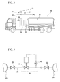
- Fig. 1 A and B show overall views of examples of the hydrogen gas delivery method of the present invention.
- the components and parts shown in the figures are not limited in their numbers, positions, size and capacities, as far as they do not cause any problem. More than one component/part, for example, may be used even when the figures show only one component/part.
- Liquefied hydrogen produced at the plant 10 is stored in the supply tank 11 (see Fig. 1-A). Liquefied hydrogen in the supply tank 11 is transferred to the delivery storage tank 21 of the delivery vehicle 20 by a pump (not shown) and through a charge hose (not shown).
- the pressure inside the delivery storage tank 21 is about 2 atm, and the temperature of liquefied hydrogen is approximately -253°C.
- liquefied hydrogen in the delivery storage tank 21 is vaporized into hydrogen gas and then filled into the storage vessel 31 (Fig. 1-B).
- hydrogen is supplied through the exit valve 24 of the vaporizer 23 connected to the entrance valve 32 of the storage vessel 31 via the supply pipe 25.
- the liquefied hydrogen in the delivery storage tank 21 is filled into the storage vessel 31 at the user's sites as a hydrogen gas. Care has to be taken, because liquefied hydrogen in the delivery storage tank 21 is at a cryogenic temperature. If a too large amount of liquefied hydrogen is fed from the delivery storage tank 21 to the vaporizer 23, heat exchange is conducted insufficiently at the vaporizer 23, and therefore the temperature of hydrogen gas at the exit of the vaporizer 23 becomes so low that it may cause low temperature brittleness of the parts such as the connection between the supply pipe 25 and entrance valve 32. Also, in some cases, liquefied hydrogen may still remain in the hydrogen gas and may cause low temperature brittleness of the storage vessel 31.
- a suitable means it is preferable to control the temperature of hydrogen gas by a suitable means. Any suitable method can be used.
- One example is to adjust the opening of the exit valve 24 to close direction and reduce the flow to the storage vessel 31, when a large amount of frost is observed on the vaporizer 23, since the frost indicate that heat exchange is not catching up the flow of the liquefied hydrogen.
- Another example is to measure the temperature of the gas in the supply pipe directly to control the opening of the exit valve 24.
- Yet another example is to control the flow of liquefied hydrogen to the vaporizer 23.
- the temperature of the hydrogen gas supplied into the storage vessel 31, increases due to adiabatic compression. It is, therefore, desirable to supply hydrogen gas at a temperature as low as possible. It is preferable to control the temperature of hydrogen gas in the vicinity of the exit valve from about -30°C to 30°C. Temperatures lower than -30°C may cause low temperature brittleness, whereas, temperatures higher than 30°C may cause insufficient filling due to an increase of the temperature caused by adiabatic compression at the time of filling.
- the numbers and volumes of delivery storage tanks 21 and storage vessels 31 are not limited in the present invention, and any numbers and volumes can be chosen.
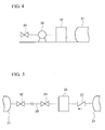
- a temperature control means 40 is disposed on the supply pipe 25 connecting between the exit valve 24 and entrance valve 32.
- the temperature control means 40 comprises a flow control valve 41 disposed on the supply pipe 25, a thermometer 42 measuring the temperature of gas inside the supply pipe 25 and a control mechanism to control the opening of the flow control valve 41 based on the signal from the thermometer 42.
- the arrangement allows automatic control of the temperatures of hydrogen gas supplied to the storage vessel 31 within a pre-specified temperature range.
- the flow control valve 41 may function as the exit valve 24 at the same time. Instead of providing the flow control valve 41, it is possible to manually control the opening of the exit valve 24 based on warning sounds generated when the thermometer 42 measures temperatures higher, or lower, than the specified temperature range.
- Fig. 2 shows an example wherein the vaporizer 23 is disposed between the driver's cabin and the delivery storage tank 21, the position of the vaporizer 23 can be determined based on the total weight balance and the like of the delivery vehicle.
- the vaporizer 23 may be placed rearward (at the end of the carriage), above, below and/or sides or the like of the delivery storage tank 21. Numbers of the vaporizer(s) and delivery tank(s) may be determined arbitrarily.
- a check valve 27 and a closed vessel 28 are disposed in this order between the delivery storage tank 21 and exit valve 24.
- the exit valve 24 is first opened and liquefied hydrogen is introduced into the closed vessel 28 from the delivery storage tank 21.
- the exit valve 24 is closed when predetermined amount of liquefied hydrogen is filled.
- Other apparatuses may be placed on the supply pipe between the entrance valve 32 an exit valve 24.
- the check vale 27 allows flow toward the direction to the closed vessel 28 only, as indicated by an arrow in the figure, and prevents a reverse flow. Therefore, liquefied hydrogen is closed in the closed vessel 28.
- the system of this embodiment is preferably designed in such a way that filling is completed in one attempt.
- a mobile carriage with a delivery storage tank may be used with a towing vehicle; or, a detachable delivery storage tank may be used, wherein the detachable delivery storage tank is filled with liquefied hydrogen at a plant, and then the filled detachable delivery storage tank is mounted on a truck having a pressurizing/gasifying means.
- the present invention provides a novel method for supplying hydrogen gas and a liquefied hydrogen delivery vehicle, which can replace the conventional "liquid transportation/liquid supply” and "gas transportation/gas supply”.
- the present invention is applicable to various industries using hydrogen gas, including petroleum, chemical, semiconductor, glass, metal and automobile industries, and provides a method for supplying hydrogen gas in significantly high economical efficiencies with much less investment.
Landscapes
- Engineering & Computer Science (AREA)
- Mechanical Engineering (AREA)
- General Engineering & Computer Science (AREA)
- Filling Or Discharging Of Gas Storage Vessels (AREA)
Applications Claiming Priority (2)
| Application Number | Priority Date | Filing Date | Title |
|---|---|---|---|
| JP2005091829A JP2006275091A (ja) | 2005-03-28 | 2005-03-28 | 水素ガスの供給方法及び液化水素輸送車 |
| PCT/JP2006/305684 WO2006103987A1 (fr) | 2005-03-28 | 2006-03-22 | Methode d’approvisionnement en hydrogene gazeux et vehicule pour transporter de l’hydrogene liquide |
Publications (1)
| Publication Number | Publication Date |
|---|---|
| EP1865247A1 true EP1865247A1 (fr) | 2007-12-12 |
Family
ID=37053246
Family Applications (1)
| Application Number | Title | Priority Date | Filing Date |
|---|---|---|---|
| EP06729651A Withdrawn EP1865247A1 (fr) | 2005-03-28 | 2006-03-22 | Methode d'approvisionnement en hydrogene gazeux et vehicule pour transporter de l'hydrogene liquide |
Country Status (3)
| Country | Link |
|---|---|
| EP (1) | EP1865247A1 (fr) |
| JP (1) | JP2006275091A (fr) |
| WO (1) | WO2006103987A1 (fr) |
Cited By (2)
| Publication number | Priority date | Publication date | Assignee | Title |
|---|---|---|---|---|
| WO2010112899A1 (fr) * | 2009-04-01 | 2010-10-07 | Dominion Technology Gases Limited | Système de remplissage de cylindre de gaz |
| WO2024003858A3 (fr) * | 2022-06-30 | 2024-02-22 | Saipem S.P.A. | Procédé de conversion de dioxyde de carbone en gns ou gnl et stockage d'hydrogène |
Families Citing this family (4)
| Publication number | Priority date | Publication date | Assignee | Title |
|---|---|---|---|---|
| JP2014149059A (ja) * | 2013-02-04 | 2014-08-21 | Iwatani Internatl Corp | ガス充填装置およびガス充填方法 |
| JP6324120B2 (ja) * | 2014-03-05 | 2018-05-16 | 日立オートモティブシステムズメジャメント株式会社 | ガス充填装置 |
| JP6324169B2 (ja) * | 2014-03-31 | 2018-05-16 | 日立オートモティブシステムズメジャメント株式会社 | ガス充填装置 |
| JP2020148240A (ja) * | 2019-03-13 | 2020-09-17 | 本田技研工業株式会社 | ガス充填方法 |
Family Cites Families (2)
| Publication number | Priority date | Publication date | Assignee | Title |
|---|---|---|---|---|
| US5762119A (en) * | 1996-11-29 | 1998-06-09 | Golden Spread Energy, Inc. | Cryogenic gas transportation and delivery system |
| JP2004360800A (ja) * | 2003-06-05 | 2004-12-24 | Hitachi Constr Mach Co Ltd | 圧縮天然ガス供給装置 |
-
2005
- 2005-03-28 JP JP2005091829A patent/JP2006275091A/ja not_active Withdrawn
-
2006
- 2006-03-22 WO PCT/JP2006/305684 patent/WO2006103987A1/fr active Application Filing
- 2006-03-22 EP EP06729651A patent/EP1865247A1/fr not_active Withdrawn
Non-Patent Citations (1)
| Title |
|---|
| See references of WO2006103987A1 * |
Cited By (2)
| Publication number | Priority date | Publication date | Assignee | Title |
|---|---|---|---|---|
| WO2010112899A1 (fr) * | 2009-04-01 | 2010-10-07 | Dominion Technology Gases Limited | Système de remplissage de cylindre de gaz |
| WO2024003858A3 (fr) * | 2022-06-30 | 2024-02-22 | Saipem S.P.A. | Procédé de conversion de dioxyde de carbone en gns ou gnl et stockage d'hydrogène |
Also Published As
| Publication number | Publication date |
|---|---|
| JP2006275091A (ja) | 2006-10-12 |
| WO2006103987A1 (fr) | 2006-10-05 |
Similar Documents
| Publication | Publication Date | Title |
|---|---|---|
| US11519556B2 (en) | Gaseous hydrogen storage system with cryogenic supply | |
| US5924291A (en) | High pressure cryogenic fluid delivery system | |
| US6810924B2 (en) | Compressed gas stream introduction method and filling station | |
| EP1492980B1 (fr) | Systeme de refroidissement de reservoir | |
| CN105683643B (zh) | 燃料罐 | |
| EP1865247A1 (fr) | Methode d'approvisionnement en hydrogene gazeux et vehicule pour transporter de l'hydrogene liquide | |
| WO2004068025A2 (fr) | Station de ravitaillement en hydrogene transportable | |
| EP2466187A1 (fr) | Conteneur de stockage de gaz | |
| US9383063B2 (en) | Hydrogen dispensing system and method thereof | |
| CN102803817B (zh) | 将氢气装入容器内的方法和灌装设备 | |
| US20080178612A1 (en) | Method for Supplying Hydrogen Gas and Liquefied Hydrogen Delivery Vehicle | |
| US20080202629A1 (en) | Two-Step-Process for Filling Gas Containers for Airbag Systems and Gas Filling Device for a Two-Step-Filling Process | |
| US20230417368A1 (en) | Method and conveying device | |
| WO2010151107A1 (fr) | Dispositif et procédé de distribution de gnl | |
| CN116176268A (zh) | 燃料输送系统和操作交通工具的方法 | |
| CN108953988B (zh) | 一种液氢汽化及自增压装置 | |
| US20070186991A1 (en) | Process and arrangement for filling high pressure gas containers using a filling tube | |
| KR20140086204A (ko) | 액화천연가스 재기화 장치 | |
| US10753540B2 (en) | Systems and methods for converting cryogenic liquid natural gas to high pressure natural gas and to low pressure natural gas and retain all converted product and to further dispense only by voluntary actions of the user | |
| JP2007009981A (ja) | 液化ガス供給設備及び液化ガス供給方法 | |
| US20040055315A1 (en) | Pressure pod cryogenic fluid expander | |
| JP2018062992A (ja) | 高圧水素製造システム | |
| US20150121906A1 (en) | Systems and Methods for Converting Liquid Natural Gas to Compressed Natural Gas and to Low Pressure Natural Gas | |
| EP1813853B1 (fr) | Réservoir pour gaz haute pression et méthode de remplissage | |
| CN112384730B (zh) | 包括内部增压器的流体罐 |
Legal Events
| Date | Code | Title | Description |
|---|---|---|---|
| PUAI | Public reference made under article 153(3) epc to a published international application that has entered the european phase |
Free format text: ORIGINAL CODE: 0009012 |
|
| 17P | Request for examination filed |
Effective date: 20070831 |
|
| AK | Designated contracting states |
Kind code of ref document: A1 Designated state(s): DE |
|
| DAX | Request for extension of the european patent (deleted) | ||
| RBV | Designated contracting states (corrected) |
Designated state(s): DE |
|
| STAA | Information on the status of an ep patent application or granted ep patent |
Free format text: STATUS: THE APPLICATION HAS BEEN WITHDRAWN |
|
| 18W | Application withdrawn |
Effective date: 20100105 |