EP1864929B1 - A soft roll material-translation device - Google Patents
A soft roll material-translation device Download PDFInfo
- Publication number
- EP1864929B1 EP1864929B1 EP06722018.6A EP06722018A EP1864929B1 EP 1864929 B1 EP1864929 B1 EP 1864929B1 EP 06722018 A EP06722018 A EP 06722018A EP 1864929 B1 EP1864929 B1 EP 1864929B1
- Authority
- EP
- European Patent Office
- Prior art keywords
- turning
- folding arm
- screw
- frame
- rod pair
- Prior art date
- Legal status (The legal status is an assumption and is not a legal conclusion. Google has not performed a legal analysis and makes no representation as to the accuracy of the status listed.)
- Active
Links
- 238000013519 translation Methods 0.000 title claims description 20
- 239000000463 material Substances 0.000 claims description 50
- 230000001105 regulatory effect Effects 0.000 claims description 17
- 238000005520 cutting process Methods 0.000 claims description 16
- 238000012856 packing Methods 0.000 description 28
- 238000007789 sealing Methods 0.000 description 5
- 230000007246 mechanism Effects 0.000 description 4
- 238000000034 method Methods 0.000 description 4
- 230000001276 controlling effect Effects 0.000 description 2
- 238000003754 machining Methods 0.000 description 2
- 239000002985 plastic film Substances 0.000 description 2
- 229920006255 plastic film Polymers 0.000 description 2
- 230000005540 biological transmission Effects 0.000 description 1
- 230000006835 compression Effects 0.000 description 1
- 238000007906 compression Methods 0.000 description 1
- 238000013461 design Methods 0.000 description 1
- 239000004744 fabric Substances 0.000 description 1
- 238000004519 manufacturing process Methods 0.000 description 1
- 210000000056 organ Anatomy 0.000 description 1
- 239000000123 paper Substances 0.000 description 1
- 239000004033 plastic Substances 0.000 description 1
- 229920003023 plastic Polymers 0.000 description 1
- 238000012545 processing Methods 0.000 description 1
- 230000002035 prolonged effect Effects 0.000 description 1
Images


Classifications
-
- B—PERFORMING OPERATIONS; TRANSPORTING
- B65—CONVEYING; PACKING; STORING; HANDLING THIN OR FILAMENTARY MATERIAL
- B65H—HANDLING THIN OR FILAMENTARY MATERIAL, e.g. SHEETS, WEBS, CABLES
- B65H35/00—Delivering articles from cutting or line-perforating machines; Article or web delivery apparatus incorporating cutting or line-perforating devices, e.g. adhesive tape dispensers
- B65H35/02—Delivering articles from cutting or line-perforating machines; Article or web delivery apparatus incorporating cutting or line-perforating devices, e.g. adhesive tape dispensers from or with longitudinal slitters or perforators
-
- B—PERFORMING OPERATIONS; TRANSPORTING
- B65—CONVEYING; PACKING; STORING; HANDLING THIN OR FILAMENTARY MATERIAL
- B65H—HANDLING THIN OR FILAMENTARY MATERIAL, e.g. SHEETS, WEBS, CABLES
- B65H23/00—Registering, tensioning, smoothing or guiding webs
- B65H23/02—Registering, tensioning, smoothing or guiding webs transversely
- B65H23/032—Controlling transverse register of web
- B65H23/035—Controlling transverse register of web by guide bars
Definitions
- the present invention relates to a soft coiled material translation device for a pillow type of automatic packing machine, or other mechanical device for machining and cutting after severing.
- a vertical pillow type of automatic packing machine or a horizontal pillow type of automatic packing machine inefficiently packs a row of articles with one roll of film.
- some packing machine manufacturers develop a kind of dual-path automatic packing machine.
- This kind of dual-path automatic packing machine combines two (horizontal) pillow type of automatic packing machines back to back with one frame shared.
- the combination of the two automatic packing machines is a simple building block's design in the structure. Two independent transmission systems, two independent electrical systems, two independent photoelectric tracking systems, two independent longitudinal sealing devices, and two independent transverse sealing and cutting devices are adjusted, operated and controlled respectively in this kind of dual-path automatic packing machine.
- DE 3203160A1 discloses a variable-tension device, in which the two mutually parallel guide rods joined together firmly at the longitudinal ends by means of connecting pieces and mounted pivotably about an axis extending parallel to the longitudinal direction of the rods.
- US 2004/0021032A1 discloses a web expanding device, of which the first and second deflecting means are used to expand the web strand Br and Bl formed apart from each other in parallel.
- the first deflecting means are mounted in a frame in fixed position in relation to one another and the first deflecting means is not rotatable.
- the first deflecting means are firmly connected to one another in the middle in the area of the "arrowhead”.
- the second deflecting means are rotatably mounted on the carriages which are movable along separate linear guides.
- the separate linear guides are rigid parts of the frame.
- US4107900A discloses an apparatus for forming and filling bags of synthetic plastics material. During operation of the apparatus of US4107900A , the tube is divided into two strips; the two strips pass over two guide rollers respectively, so that the two strips are apart formed from each other in a direction perpendicular to their moving direction.
- US 2 990 989 A discloses a mechanism for feeding web sheets from roll material onto a compensator in a side-by-side arrangement, but at different rates.
- the apparatus compensates for fluctuations of feeding speeds by introducing a rocker-type compensator for taking up slack and exerting tension on the web sheet to keep the roll turning even when the portion of the web sheet beyond the compensator is momentarily quiescent.
- the problem to be solved by this invention is that the existing pillow type of automatic packing machine uses one roll of film to pack a row of articles inefficiently.
- the present invention provides a soft coiled material translation device to solve the above problem.
- a soft coiled material translation device includes a frame (1).
- a left turning device (2) and a right turning device (3) are mounted on the frame (1), a left folding rod pair (4) is mounted on the left turning device (2), a right folding rod pair (5) is mounted on the right turning device (3), wherein the left folding rod pair comprises a left upper folding arm and a left lower folding arm; and the right folding rod pair comprises a right upper folding arm and a right lower folding arm, wherein the left turning device (2) is adapted to be turned around axis of a turning centre (6) to adjust an angle between the folding arms and a direction in which the soft coiled material goes ahead, the right turning device (3) is adapted to be turned around the axis of a turning centre (6) to adjust another angle between the folding arms of the right folding rod pair (5) and the direction in which the soft coiled material goes ahead, and each of the left turning device (2) and the right turning device (3) comprises a turning seat (7), a turning guide unit and a turning regulating unit; wherein the turning seat (7)
- the frame (1) is configured to support and fix other components and parts.
- the left turning device (2) and the right turning device (3) are respectively mounted on the frame (1), and are connected with the frame (1) via revolving pair.
- the turning centre (6) is an axis; left turning device (2) and right turning device (3) are turned around the turning centre (6).
- the left folding rod pair (4) and the right folding rod pair (5) each includes two folding arms. Two folding arms of the same folding rod pair are parallel to each other substantially; alternatively there would be an angle between the two folding arms of the same folding rod pair.
- the left folding rod pair (4) and the right folding rod pair (5) may be respectively mounted on the left turning device (2) and the right turning device (3) directly, or be mounted on the left turning device (2) and the right turning device (3) indirectly via other components and parts.
- the left turning unit (2) and the right turning units (3) drive left folding rod pair (4) and right folding rod pair (5) to be turned, and adjust the angle between the folding arms and a direction in which the soft coiled material goes ahead. The change of the angle between the folding arms and the direction in which the soft coiled material goes ahead allows a distance change between two soft coiled materials.
- a generating line (4c) of left lower folding arm (4b) and a generating line (5c) of right lower folding arm (5b) track through the turning centre (6) in general.
- the soft coiled material is turned back by the lower folding arm at first (i.e., the soft coiled material first goes ahead and then goes in an opposite direction), then is turned back again by the upper folding arm, and goes ahead again.
- the generating line (4c) of left lower folding arm (4b) is not parallel to the generating line (5c) of right lower folding arm (5b), there will be a variable distance between left soft coiled material and right soft coiled material after the two soft coiled materials pass by the left folding rod pair 4 and the right folding rod pair (5).
- the left upper folding arm (4a), the left lower folding arm (4b), the right upper folding arm (5a) and the right lower folding arm (5b) touch with the soft coiled material by each working surface, the generating line of the each working surface is a straight line, no matter in which shape each cross section is.
- each of the two soft coiled materials i.e., the tension of the left side of the soft coiled material is equal to the tension of the right side
- the generating lines on the working surfaces of the left upper folding arm (4a) and the left lower folding arm (4b) should be parallel to each other
- the generating lines on the working surfaces of the right upper folding arm (5a) and the right lower folding arm (5b) should also be parallel to each other.
- the two soft coiled materials can go ahead in an unchanged direction.
- the generating line (4c) of the left lower folding arm (4b) and the generating line (5c) of the right lower folding arm (5b) refer to a generating line on which the soft coiled material is turned back in movement direction of the soft coiled material.
- the turning regulating unit can adopt one of the following organs: gear-sector wheel, worm sector-worm gear pair, revolving pair, and screw pair.
- the left folding rod pair (4) may be mounted directly on the left turning device (2), or may be mounted indirectly on the left turning device (2) via other components and parts.
- the right folding rod pair (5) may be mounted directly on the right turning device (3), or may be mounted indirectly on the right turning device (3) via other components and parts.
- the turning guide unit includes a slide (8) and a turning slide guide (31) on the frame (1).
- the turning regulating unit includes a sector gear (9) and a gear (10), and the sector gears (9) of the left turning device (2) and the right turning device (3) are each fixed on the left and right sides of the frame (1) respectively.
- Circle centre of sector gear (9) of the left turning device (2) and the right turning device (3) each coincides with the turning centre (6).
- the gear (10) meshes with the sector gear (9), a gear shaft (11) of the gear (10) is mounted on the turning seat (7), and a knob (12) is mounted on the gear shaft (11).
- the slide (8) is fixed on the turning seat (7), and is slideably fit with the turning slide guide (31) on the frame (1), and the circle centres of turning slide guides (31) each coincides with the turning centre (6).
- the knob (12) may be replaced by a handle or other mechanisms having similar function.
- the knob (12) is turned, and the gear (10) is driven by the gear shaft (11) and rolls on the sector gear (9).
- the gear (10) drives the turning seat (7) and the slide (8) via the gear shaft (11), and the turning seat (7) and the slide (8) swing around the turning centre (6) along the turning slide guide (31) of the frame (1).
- the turning regulating unit also includes a first screw (14) and a knob (15); the first screw (14) is fitted with screw hole on the slide (8), and one end of the first screw (14) may touch the frame (1) while the other end of the first screw (14) is connected with the knob (15).
- the first screw (14) and the knob (15) are configured to loosen the turning seat (7) or lock the turning seat (7) on the frame (1), and the knob (15) may be replaced by a handle or other mechanisms having similar function. Since the slide (8) and the turning seat (7) are fixed to each other, the turning seat (7) may be loosened or locked by loosening or locking the slide (8). According to this invention, the first screw (14) and the knob (15) may also be mounted on the turning seat (7), and the turning seat (7) may be directly loosened by the first screw (14) and the knob (15). The solution of mounting the first screw (14) and the knob (15) on the turning seat (7) is also covered in scope of the invention. Alternatively, other types of devices which can make the turning seat (7) be loosened or locked on the frame (1) may replace the first screw (14) and the knob (15).
- the turning guide unit may includes pin roll (16) on the frame (1), and shaft hole on the turning seat (7) of the left turning device (2) and the right turning device (3).
- Each turning seat (7) of the left turning device (2) and the right turning device (3) is mounted on the pin roll (16) via the shaft hole.
- the axis of the pin roll (16) is the turning centre (6) of the left turning device (2) and the right turning device (3).
- the turning regulating unit includes an arc slot (17), a pin roll (18), an adjusting shaft (19), a second screw (20), a third screw (21) and a pin roll (22).
- the arc slot (17) is on the frame (1), and centre of the arc slot (17) coincides with the turning centre (6).
- the middle of the pin roll (18) is located in the arc slot (17), one end of the pin roll (18) is fixed on the turning seat (7), and the other end of the pin roll (18) is linked with the second screw (20).
- One end of the pin roll (22) is fixed on the frame (1), and the other end of the pin roll (22) is linked with the second screw (20).
- Two ends of the adjusting shaft (19) both have internal threads with opposite rotation.
- the thread rotation of the second screw (20) is opposite to the thread rotation of the third screw (21).
- the internal threads at two ends of adjusting shaft (19) are fitted with the second screw (20) and the third screw (21) respectively.
- the pin roll (18) performs arc movement along the arc slot (17), and drives the turning seat (7) to swing around the turning centre (6).
- the adjusting shaft (19) is turned, and the screws (20, 21) on the adjusting shaft (19) respectively stretch out or draw back in opposite direction.
- the turning seat (7) is driven to swing around the turning centre (6) via the pin roll (18).
- At least one of the left upper folding arm (4a) and the right upper folding arm (5a) is mounted on moving bed (23), and the moving bed (23) is mounted on the turning seat (7).
- the moving bed (23) has a moving guide unit and a moving adjustment unit.
- the left upper folding arm (4a) and the right upper folding arm (5a) can be mounted directly on the moving bed (23), or can be indirectly mounted on the moving bed (23) via other components and parts.
- the moving bed (23) and the turning seat (7) are linked with each other via a moving pair (prismatic pair), and the moving bed (23) can move on the turning seat (7).
- the moving bed (23) is configured to driving the left upper folding arm (4a) to move in parallel with the left lower folding arm (4b), or is configure to drive the right upper folding arm (5a) to move in parallel with the right lower folding arm (5b).
- the moving guide unit is configured to guide the moving bed (23) to move straightly on the turning seat (7).
- the moving adjustment unit is configured to adjust movement distance of the moving bed 23 moving on the turning seat (7), i.e., is configured to adjust the distance between the left upper folding arm (4a) and the lower folding arm (5a), or is configured to adjust the distance between the left upper folding arm (4a) and the lower folding arm (5a).
- the left upper folding arm (4a) and the right upper folding arm (5a) are mounted on the turning seat (7) or the moving bed (23) via swing pin rolls (24) respectively. And each of the left upper folding arm (4a) and the right upper folding arm (5a) has a swinging adjustment device.
- the swing pin rolls (24) of the left upper folding arm (4a) and the right upper folding arm (5a) may be mounted either on the turning seat (7), or on the moving bed (23), but at least one swing pin roll (24) is mounted on the moving bed (23).
- Each of the left upper folding arm (4a) and the right upper folding arm (5a) may swing around the swing pin roll (24).
- the angle between the left upper folding arm (4a) and the left lower folding arm (4b) can be changed, and the angle between the right upper folding arm (5a) and the right lower folding arm (5b) can be changed.
- the change of the angle between the left upper folding arm (4a) and left lower folding arm (4b), or the change of the angle between the right upper folding arm (5a) and the right lower folding arm (5b) allows adjusting tension between left side and right sides of the soft coiled material turned back.
- the swinging adjustment device may be a slide and screw pair, a cylindrical pair and screw pair, eccentric, or cam etc.
- the swinging adjustment device is configured to adjust angle through which the left upper folding arm (4a) and the right upper folding arm (5a) moves, and lock the left upper folding arm (4a) and the right upper folding arm (5a) at the angle.
- a driving roll (25) and a knife rest (27) are mounted on the frame (1), the cutting knife (26) is mounted on the knife rest (27).
- the driving roll (25) is located in front of the left upper folding arm (4a) and the right upper folding arm (5a).
- the cutting knife (26) is located in the middle of the driving roll (25).
- the driving roll (25) is configured to drive the soft coiled material to go and pass by the folding rod pair (4a) and the folding rod pair (5a). If this invention is used in a packing machine, the driving roll (25) can be replaced by a film driving roll of the packing machine.
- the extension line of the cutting knife goes between the folding rod pair (4) and the folding rod pair (5), and the cutting knife is configured to cut a soft coiled material into two belts longitudinally.
- a steering roll (28) is mounted on the frame (1), and the steering roll (28) is located behind the left lower folding arm (4b) and the right lower folding arm (5b).
- the steering roll (28) is configured to guide two soft coiled materials with an increased width after the two soft coiled materials are severed and turned back. If this invention is used in the packing machine, the frame (1) may swing around the driving roll (25) and may be adjusted. The steering roll (28) may move along surface of the frame (1) in a parallel way, the steering roll (28) may replace a bag making compact adjusting roller of the packing machine.
- the translation device of this invention is mainly applied in the pillow type of (vertical or horizontal) automatic packing machine or other mechanical devices for machining and cutting after severing.
- a few mechanisms are added to the automatic packing machine, and the working efficiency of the automatic packing machine is doubled.
- two rows of articles can be automatically packed in one automatic packing machine with the translation device of present invention, a set of parallel conveyor chain, a bag making device, a longitudinal sealing device, an
- the working efficiency of the automatic packing machine can be doubled without increasing the number of operating staff.
- the first embodiment discloses a soft coiled material translation device used on a pillow type of packing machine.
- the soft coiled material translation device includes frame 1, left turning device 2, right turning device 3, left folding rod pair 4 and right folding rod pair 5.
- Left turning device 2 and right turning device 3 are symmetrically mounted on the left and the right sides of frame 1, respectively.
- Left turning device 2 and right turning device 3 can be turned on axis of turning centre 6 on frame 1.
- Left folding rod pair 4 is mounted on left turning device 2, and right folding rod pair 5 is mounted on right turning device 3.
- Left turning device 2 and right turning device 3 each includes turning seat 7, turning guide unit and turning regulating unit.
- Left folding rod pair 4 and right folding rod pair 5 are mounted on turning seats 7 of left turning device 2 and right turning device 3 respectively.
- Left folding rod pair 4 includes upper folding arm 4a and lower folding arm 4b;
- right folding rod pair 5 includes upper folding arm 5a and lower folding arm 5b; the working parts of upper folding arm 4a, lower folding arm 4b, upper folding arm 5a and lower folding arm 5b are round bars.
- the turning guide unit includes slide 8 and turning slide guide 31 on frame 1, the turning regulating unit includes sector gears 9 and gears 10, and turning slide guide 31 is fixed on sector gear 9 with a parallel connection.
- Sector gears 9 of left turning device 2 and right turning device 3 are fixed on the left and right sides of frame 1 respectively, and circle centre of sector gear 9 coincides with turning centre 6.
- Gears 10 meshes with sector gears 9; gear shaft 11 of gear 10 is mounted on turning seat 7; and knob 12 is mounted on gear shaft 11.
- Slide 8 is fixed on turning seat 7 via screw 13, and has turning slide guide 31 having a concave. Turning slide guide 31 having a concave covers turning slide guide 31 having a convexity of frame 1, and circle centre of turning slide guide 31 and sector gear 9 respectively coincide with turning centre 6.
- the turning regulating unit also includes screw 14 and knob 15.
- Screw 14 is fitted with a screw hole on slide 8; one end of screw 14 touches frame 1, the other end of screw 14 is connected with knob 15.
- Upper folding arm 4a and upper folding arm 5a are mounted on left and right moving beds 23 respectively.
- Left and right moving beds 23 are mounted on left and right turning seats 7.
- Lower folding arm 4b and lower folding arm 5b are directly fixed on left and right turning seats 7 respectively, lower generating line 4c of lower folding arm 4b and lower generating line 5c of lower folding arm 5b each passes turning centre 6.
- Moving bed 23 has a moving guide unit and a moving adjustment unit.
- the moving guide unit includes guiding slot 29, screw 30 and screw 32.
- Guiding slot 29 is a straight slot and perpendicular to the axis of lower folding arm 4b or lower folding arm 5b. Screw 30 and screw 32, passing guiding slot 29, are fitted with two screw holes on turning seat 7 respectively. The line through screw 30 and screw 32 is perpendicular to the axis of the lower folding arm 4b or lower folding arm 5b. Moving bed 23 is mounted on turning seat 7, and straightly moves through guiding slot 29 along screw 30 and screw 32.
- the moving adjustment unit includes adjusting shaft 34, screw 35 and screw 36. Two ends of adjusting shaft 34 have internal threads with opposite rotation, and thread rotation of screw 35 is opposite to thread rotation of screw 36. Screw 35 and screw 36 are fitted with the internal threads at two ends of adjusting shaft 34 respectively. Screw 35 and screw 36 are mounted on turning seat 7 and moving bed 23 respectively, and axis of adjusting shaft 34, screw 35 and screw 36 are perpendicular to the axis of the lower folding arm 4b or lower folding arm 5b.
- Upper folding arm 4a and upper folding arm 5a are mounted on moving bed 23 via swing pin roll 24 respectively.
- Each of upper folding arm 4a and upper folding arm 5a has a swinging adjustment device.
- the swinging adjustment device includes screw 37, knob 38 and spring 39.
- Screw 37 is fitted with screw hole on moving bed 23, and one end of screw 37 touches one side of tail of upper folding arm 4a or upper folding arm 5a, and knob 38 is mounted on the other end of the screw 37; spring 39 can be a compression spring, and one end of spring 39 touches moving bed 23, the other end of spring 39 touches the other side of tail of upper folding arm 4a or upper folding arm 5a.
- Driving roll 25 and knife rest 27 are mounted on frame 1; cutting knife 26 is mounted on knife rest 27.
- Driving roll 25 is located in front of upper folding arm 4a and upper folding arm 5a, and is replaced with a film driving roll of the packing machine.
- Cutting knife 26 is located in middle of driving roll 25.
- Steering roll 25 is mounted on frame 1, and steering roll 28 is located behind lower folding arm 4b and lower folding arm 5b.
- the second embodiment discloses a soft coiled material translation device used on a pillow type of packing machine.
- the soft coiled material translation device includes frame 1, left turning device 2, right turning device 3, left folding rod pair 4 and right folding rod pair 5.
- Left turning device 2 and right turning device 3 each includes turning seat 7, a turning guide unit and a turning regulating unit.
- Pin roll 16 is fixed on frame 1, turning seat 7 of left turning device 2 or right turning device 3 is mounted on pin roll 16 via a shaft hole, and the axis of pin roll 16 is turning centre 6 of left turning device 2 and right turning device 3.
- Left folding rod pair 4 is mounted on left turning device 2, and right folding rod pair 5 is mounted on right turning device 3.
- Left folding rod pair 4 and right folding rod pair 5 are respectively mounted on turning seats 7 of left turning device 2 and right turning device 3.
- Left folding rod pair 4 includes upper folding arm 4a and lower folding arm 4b;
- right folding rod pair 5 includes upper folding arm 5a and lower folding arm 5b; working part of upper folding arm 4a, lower folding arm 4b, upper folding arm 5a and lower folding arm 5b are round bars.
- the turning guide unit includes pin roll 16 of frame 1, shaft holes on turning seats 7 of left turning device 2 and right turning device 3.
- the turning regulating unit includes adjusting shaft 19, screw 20, screw 21 and pin roll 22.
- Arc slot 17 is fixed on frame 1, and circle centre of arc slot 17 coincides with turning centre 6.
- the middle part of pin roll 18 is located in arc slot 17, and one end of pin roll 18 is fixed on turning seat 7, the other end of pin roll 18 is connected with screw 21.
- One end of pin roll 22 is fixed on frame 1; the other end of pin roll 22 is connected with screw 20.
- Two ends of adjusting shaft 19 have internal threads with opposite rotation; thread rotation of screw 20 is opposite to thread rotation of screw 21.
- the internal threads of adjusting shaft 19 are fitted with screw 20 and screw 21 respectively.
- Lower folding arm 4b and lower folding arm 5b are directly mounted on left turning seat 7 and right turning seat 7 respectively, and lower generating line 4c of lower folding arm 4b and lower generating line 5c of lower folding arm 5b each passes turning centre 6.
- Upper folding arm 4a is mounted on left turning seat 7 via swing pin roll 24, and upper folding arm 4a has a swinging adjustment device.
- Upper folding arm 5a is mounted on moving bed 23 which is mounted on right turning seat 7.
- Moving bed 23 has a moving guide unit and a moving adjustment unit.
- the moving guide unit includes dovetail guide 43 on moving bed 23 and dovetail slot 44 on turning seat 7. Dovetail guide 43 and dovetail slot 44 are fitted with each other, moving bed 23 is mounted on right turning seat 7, and moving bed 23 moves straightly on right turning seat 7 via dovetail guide 43 and dovetail slot 44. Dovetail guide 43 and dovetail slot 44 are perpendicular to the axis of lower folding arm 4b.
- the moving adjustment unit includes adjusting shaft 45, screw 46 and screw 47. Two ends of adjusting shaft 45 have internal threads with opposite rotation; thread rotation of screw 46 is opposite to thread rotation of screw 47. Screw 46 and screw 47 are fitted with the internal threads of two ends of adjusting shaft 45 respectively.
- Screw 46 and screw 47 are mounted on right turning seat 7 and moving bed 23 respectively.
- the axis of adjusting shaft 45, screw 46 and screw 47 are perpendicular to the axis of lower folding arm 5b.
- Upper folding arm 5a is mounted on moving bed 23 via swing pin roll 24, and upper folding arm 5a has a swinging adjustment device.
- Each of winging controlling devices of upper folding arm 4a and upper folding arm 5a includes screw 40, knob 41 and nut 42.
- Screw 40 of upper folding arm 4a is mounted on left turning seat 7, and knob 41 is mounted on one end of screw 40.
- Nut 42 of upper folding arm 4a is in the slotted hole of upper folding arm 4a, and nut 42 is fitted with screw 40.
- Nut 40 of upper folding arm 5a is mounted on moving bed 23, and knob 41 is mounted on one end of nut 40.
- Nut 42 of upper folding arm 5a is in the slotted hole of upper folding arm 5a, and is fitted with screw 40.
- Driving roll 25 and knife rest 27 are mounted on frame 1; cutting knife 26 is mounted on knife rest 27.
- Driving roll 25 is located in front of upper folding arm 4a and upper folding arm 5a.
- Cutting knife 26 is located in the middle of driving roll 25.
- Steering roll 25 is mounted on frame 1; steering roll 28 is located behind lower folding arm 4b and lower folding arm 5b.
- the third embodiment discloses a soft coiled material translation device used on a pillow type of packing machine.
- the soft coiled material translation device includes frame 1, left turning device 2, right turning device 3, left folding rod pair 4 and right folding rod pair 5.
- the third embodiment is same as the first embodiment except that locations of turning slide guide 31, the moving adjustment unit and the swinging adjustment device.
- Turning slide guide 31 is set on contact surface between frame 1 and turning seat 7.
- the moving adjustment unit includes screw 48 and knob 49, and knob 49 is fixed on one end of screw 48. Two ends of screw 48 have external threads with opposite rotation, turning seat 7 and moving bed 23 respectively have internal threads with opposite rotation, and the external threads on screw 48 are fitted with internal threads of turning seat 7 and moving bed 23 respectively.
- the swinging adjustment device includes nut 50, cylinder head 51, screw 52 and knob 53.
- Screw 52 is mounted on moving bed 23, and knob 53 is mounted on one end of knob 53.
- Nut 50 is fitted with screw 52.
- Cylinder head 51 is at the tail of upper folding arm 4a and upper folding arm 5a, and there is cylinder face 54 on cylinder head 51.
- a roll of plastic film 56 of a pillow type of packing machine is cut by cutting knife 26 into film belt 57 and film belt 58 in parallel.
- film belt 57 and film belt 58 are apart from each other, and the distance between film belt 57 and film belt 58, L, is increased, and film belt 57 and film belt 58 are still kept parallel with each other.
- film belt 57 and film belt 58 are put away by steering roll 28, and are processed in the next packing processes, such as bag making and forming, longitudinal sealing, and transverse sealing and cutting. Two rows of articles may be packed by film belt 57 and film belt 58 simultaneously.
- the turning regulating unit adjusts the angle ⁇ through which upper folding arm 4a and lower folding arm 4b rotate ,and upper folding arm 5a and lower folding arm 5b rotate, then the distance between film belt 57 and film belt 58 ,L, can be adjusted.
- the cutting error caused by the fact that film belt 57 and film belt 58 are inconsistently prolonged in subsequent processes can be adjusted by adjusting, via the moving adjustment unit, the distance between upper folding arm 4a and lower folding arm 4b, or the distance between upper folding arm 5a and lower folding arm 5b.
- the tension of the two sides of each of film belts 57 and 58 may be adjusted by adjusting, via the swinging adjustment device, the angle between upper folding arm 4a and lower folding arm 4b, or the angle between upper folding arm 5a and lower folding arm 5b.
Landscapes
- Folding Of Thin Sheet-Like Materials, Special Discharging Devices, And Others (AREA)
- Invalid Beds And Related Equipment (AREA)
- Containers And Plastic Fillers For Packaging (AREA)
- Basic Packing Technique (AREA)
Description
- The present invention relates to a soft coiled material translation device for a pillow type of automatic packing machine, or other mechanical device for machining and cutting after severing.
- At present, a vertical pillow type of automatic packing machine or a horizontal pillow type of automatic packing machine inefficiently packs a row of articles with one roll of film. In order to pack articles efficiently in a smaller floor area, some packing machine manufacturers develop a kind of dual-path automatic packing machine. This kind of dual-path automatic packing machine combines two (horizontal) pillow type of automatic packing machines back to back with one frame shared. The combination of the two automatic packing machines is a simple building block's design in the structure. Two independent transmission systems, two independent electrical systems, two independent photoelectric tracking systems, two independent longitudinal sealing devices, and two independent transverse sealing and cutting devices are adjusted, operated and controlled respectively in this kind of dual-path automatic packing machine. Two rolls of film have to be mounted on this kind of dual-path automatic packing machine, and each of the two rolls of film is independently started up and run. This kind of dual-path automatic packing machine does not need too much device space, and it does not have a decrease in cost of manufacture and manpower for operation, comparing to the cost and the manpower of two independent packing machines.
-
DE 3203160A1 discloses a variable-tension device, in which the two mutually parallel guide rods joined together firmly at the longitudinal ends by means of connecting pieces and mounted pivotably about an axis extending parallel to the longitudinal direction of the rods. -
US 2004/0021032A1 discloses a web expanding device, of which the first and second deflecting means are used to expand the web strand Br and Bl formed apart from each other in parallel. The first deflecting means are mounted in a frame in fixed position in relation to one another and the first deflecting means is not rotatable. The first deflecting means are firmly connected to one another in the middle in the area of the "arrowhead". The second deflecting means are rotatably mounted on the carriages which are movable along separate linear guides. The separate linear guides are rigid parts of the frame. -
US4107900A discloses an apparatus for forming and filling bags of synthetic plastics material. During operation of the apparatus ofUS4107900A , the tube is divided into two strips; the two strips pass over two guide rollers respectively, so that the two strips are apart formed from each other in a direction perpendicular to their moving direction. -
US 2 990 989 A discloses a mechanism for feeding web sheets from roll material onto a compensator in a side-by-side arrangement, but at different rates. The apparatus compensates for fluctuations of feeding speeds by introducing a rocker-type compensator for taking up slack and exerting tension on the web sheet to keep the roll turning even when the portion of the web sheet beyond the compensator is momentarily quiescent. - The problem to be solved by this invention is that the existing pillow type of automatic packing machine uses one roll of film to pack a row of articles inefficiently. The present invention provides a soft coiled material translation device to solve the above problem.
- A soft coiled material translation device includes a frame (1). A left turning device (2) and a right turning device (3) are mounted on the frame (1), a left folding rod pair (4) is mounted on the left turning device (2), a right folding rod pair (5) is mounted on the right turning device (3), wherein the left folding rod pair comprises a left upper folding arm and a left lower folding arm; and the right folding rod pair comprises a right upper folding arm and a right lower folding arm, wherein the left turning device (2) is adapted to be turned around axis of a turning centre (6) to adjust an angle between the folding arms and a direction in which the soft coiled material goes ahead, the right turning device (3) is adapted to be turned around the axis of a turning centre (6) to adjust another angle between the folding arms of the right folding rod pair (5) and the direction in which the soft coiled material goes ahead, and each of the left turning device (2) and the right turning device (3) comprises a turning seat (7), a turning guide unit and a turning regulating unit; wherein the turning seat (7) is connected with the frame (1) via a revolving pair, and the turning seat (7) makes a swing on the frame (1); the turning guide unit is configured to guide the turning seat (7), and make the turning seat (7) swing around the turning centre (6) on the frame (1); the turning regulating unit is configured to adjust a swing angle through which the turning seat (7) swings around the turning centre (6); wherein the left folding rod pair (4) is mounted on the turning seat (7) of the left turning device (2), and the right folding rod pair (5) is mounted on the turning seat (7) of the right turning device (3), the soft coiled material is turned back by the lower folding arm of each of the left folding rod pair (4) and the right folding rod pair (5) first, then is turned back again by the upper folding arm of each of the left folding rod pair (4) and the right folding rod pair (5), and goes ahead again.
- The frame (1) is configured to support and fix other components and parts. The left turning device (2) and the right turning device (3) are respectively mounted on the frame (1), and are connected with the frame (1) via revolving pair. The turning centre (6) is an axis; left turning device (2) and right turning device (3) are turned around the turning centre (6). The left folding rod pair (4) and the right folding rod pair (5) each includes two folding arms. Two folding arms of the same folding rod pair are parallel to each other substantially; alternatively there would be an angle between the two folding arms of the same folding rod pair. After two soft coiled materials (e.g., plastic film, paper and cloth) parallel to each other are turned back by the left folding rod pair (4) and the right folding rod pair (5) respectively, the two soft coiled materials still be parallel to each other, and the distance between the two soft coiled materials may be changed. The left folding rod pair (4) and the right folding rod pair (5) may be respectively mounted on the left turning device (2) and the right turning device (3) directly, or be mounted on the left turning device (2) and the right turning device (3) indirectly via other components and parts. The left turning unit (2) and the right turning units (3) drive left folding rod pair (4) and right folding rod pair (5) to be turned, and adjust the angle between the folding arms and a direction in which the soft coiled material goes ahead. The change of the angle between the folding arms and the direction in which the soft coiled material goes ahead allows a distance change between two soft coiled materials.
- A generating line (4c) of left lower folding arm (4b) and a generating line (5c) of right lower folding arm (5b) track through the turning centre (6) in general. The soft coiled material is turned back by the lower folding arm at first (i.e., the soft coiled material first goes ahead and then goes in an opposite direction), then is turned back again by the upper folding arm, and goes ahead again. As long as the generating line (4c) of left lower folding arm (4b) is not parallel to the generating line (5c) of right lower folding arm (5b), there will be a variable distance between left soft coiled material and right soft coiled material after the two soft coiled materials pass by the left folding rod pair 4 and the right folding rod pair (5). The left upper folding arm (4a), the left lower folding arm (4b), the right upper folding arm (5a) and the right lower folding arm (5b) touch with the soft coiled material by each working surface, the generating line of the each working surface is a straight line, no matter in which shape each cross section is. When there is a rather even tension inside, each of the two soft coiled materials (i.e., the tension of the left side of the soft coiled material is equal to the tension of the right side), the generating lines on the working surfaces of the left upper folding arm (4a) and the left lower folding arm (4b) should be parallel to each other, and the generating lines on the working surfaces of the right upper folding arm (5a) and the right lower folding arm (5b) should also be parallel to each other. In this way, upon passing by two folding arms and being turned back twice, the two soft coiled materials can go ahead in an unchanged direction. When there is an uneven tension inside each of two soft coiled materials (i.e., the tension of the left side of the soft coiled material is considerably different from the tension of the right side), there should be a certain angle between the generating lines on the working surfaces of the left upper folding arm (4a) and the left lower folding arm (4b), and there also should be a certain angle between the generating lines on the working surfaces of the right upper folding arm (5a) and the right lower folding arm (5b). In this way, after being turned back twice by two folding arms, two soft coiled materials go ahead in an unchanged direction. The generating line (4c) of the left lower folding arm (4b) and the generating line (5c) of the right lower folding arm (5b) refer to a generating line on which the soft coiled material is turned back in movement direction of the soft coiled material.
- The turning regulating unit can adopt one of the following organs: gear-sector wheel, worm sector-worm gear pair, revolving pair, and screw pair. The left folding rod pair (4) may be mounted directly on the left turning device (2), or may be mounted indirectly on the left turning device (2) via other components and parts. The right folding rod pair (5) may be mounted directly on the right turning device (3), or may be mounted indirectly on the right turning device (3) via other components and parts.
- In this invention, the turning guide unit includes a slide (8) and a turning slide guide (31) on the frame (1). The turning regulating unit includes a sector gear (9) and a gear (10), and the sector gears (9) of the left turning device (2) and the right turning device (3) are each fixed on the left and right sides of the frame (1) respectively. Circle centre of sector gear (9) of the left turning device (2) and the right turning device (3) each coincides with the turning centre (6). The gear (10) meshes with the sector gear (9), a gear shaft (11) of the gear (10) is mounted on the turning seat (7), and a knob (12) is mounted on the gear shaft (11). The slide (8) is fixed on the turning seat (7), and is slideably fit with the turning slide guide (31) on the frame (1), and the circle centres of turning slide guides (31) each coincides with the turning centre (6).
- The knob (12) may be replaced by a handle or other mechanisms having similar function. The knob (12) is turned, and the gear (10) is driven by the gear shaft (11) and rolls on the sector gear (9). The gear (10) drives the turning seat (7) and the slide (8) via the gear shaft (11), and the turning seat (7) and the slide (8) swing around the turning centre (6) along the turning slide guide (31) of the frame (1). In this invention, the turning regulating unit also includes a first screw (14) and a knob (15); the first screw (14) is fitted with screw hole on the slide (8), and one end of the first screw (14) may touch the frame (1) while the other end of the first screw (14) is connected with the knob (15).
- The first screw (14) and the knob (15) are configured to loosen the turning seat (7) or lock the turning seat (7) on the frame (1), and the knob (15) may be replaced by a handle or other mechanisms having similar function. Since the slide (8) and the turning seat (7) are fixed to each other, the turning seat (7) may be loosened or locked by loosening or locking the slide (8). According to this invention, the first screw (14) and the knob (15) may also be mounted on the turning seat (7), and the turning seat (7) may be directly loosened by the first screw (14) and the knob (15). The solution of mounting the first screw (14) and the knob (15) on the turning seat (7) is also covered in scope of the invention. Alternatively, other types of devices which can make the turning seat (7) be loosened or locked on the frame (1) may replace the first screw (14) and the knob (15).
- In this invention, the turning guide unit may includes pin roll (16) on the frame (1), and shaft hole on the turning seat (7) of the left turning device (2) and the right turning device (3). Each turning seat (7) of the left turning device (2) and the right turning device (3) is mounted on the pin roll (16) via the shaft hole. The axis of the pin roll (16) is the turning centre (6) of the left turning device (2) and the right turning device (3). The turning regulating unit includes an arc slot (17), a pin roll (18), an adjusting shaft (19), a second screw (20), a third screw (21) and a pin roll (22). The arc slot (17) is on the frame (1), and centre of the arc slot (17) coincides with the turning centre (6). The middle of the pin roll (18) is located in the arc slot (17), one end of the pin roll (18) is fixed on the turning seat (7), and the other end of the pin roll (18) is linked with the second screw (20). One end of the pin roll (22) is fixed on the frame (1), and the other end of the pin roll (22) is linked with the second screw (20). Two ends of the adjusting shaft (19) both have internal threads with opposite rotation. The thread rotation of the second screw (20) is opposite to the thread rotation of the third screw (21). The internal threads at two ends of adjusting shaft (19) are fitted with the second screw (20) and the third screw (21) respectively.
- The pin roll (18) performs arc movement along the arc slot (17), and drives the turning seat (7) to swing around the turning centre (6). The adjusting shaft (19) is turned, and the screws (20, 21) on the adjusting shaft (19) respectively stretch out or draw back in opposite direction. The turning seat (7) is driven to swing around the turning centre (6) via the pin roll (18). There is a self locking action between internal threads at two ends of the adjusting shaft (19), so that the turning seat (7) can be locked on the frame (1).
- In this invention, at least one of the left upper folding arm (4a) and the right upper folding arm (5a) is mounted on moving bed (23), and the moving bed (23) is mounted on the turning seat (7). The moving bed (23) has a moving guide unit and a moving adjustment unit.
- The left upper folding arm (4a) and the right upper folding arm (5a) can be mounted directly on the moving bed (23), or can be indirectly mounted on the moving bed (23) via other components and parts. The moving bed (23) and the turning seat (7) are linked with each other via a moving pair (prismatic pair), and the moving bed (23) can move on the turning seat (7). The moving bed (23) is configured to driving the left upper folding arm (4a) to move in parallel with the left lower folding arm (4b), or is configure to drive the right upper folding arm (5a) to move in parallel with the right lower folding arm (5b). The moving guide unit is configured to guide the moving bed (23) to move straightly on the turning seat (7). Then the distance between the left upper folding arm (4a) and the left lower folding arm (4b) is changed, or the distance between the right upper folding arm (5a) and the right lower folding arm (5b) is changed. The moving adjustment unit is configured to adjust movement distance of the moving
bed 23 moving on the turning seat (7), i.e., is configured to adjust the distance between the left upper folding arm (4a) and the lower folding arm (5a), or is configured to adjust the distance between the left upper folding arm (4a) and the lower folding arm (5a). - In the present invention, the left upper folding arm (4a) and the right upper folding arm (5a) are mounted on the turning seat (7) or the moving bed (23) via swing pin rolls (24) respectively. And each of the left upper folding arm (4a) and the right upper folding arm (5a) has a swinging adjustment device. The swing pin rolls (24) of the left upper folding arm (4a) and the right upper folding arm (5a) may be mounted either on the turning seat (7), or on the moving bed (23), but at least one swing pin roll (24) is mounted on the moving bed (23).
- Each of the left upper folding arm (4a) and the right upper folding arm (5a) may swing around the swing pin roll (24). The angle between the left upper folding arm (4a) and the left lower folding arm (4b) can be changed, and the angle between the right upper folding arm (5a) and the right lower folding arm (5b) can be changed. The change of the angle between the left upper folding arm (4a) and left lower folding arm (4b), or the change of the angle between the right upper folding arm (5a) and the right lower folding arm (5b) allows adjusting tension between left side and right sides of the soft coiled material turned back. Alternatively, the swinging adjustment device may be a slide and screw pair, a cylindrical pair and screw pair, eccentric, or cam etc. The swinging adjustment device is configured to adjust angle through which the left upper folding arm (4a) and the right upper folding arm (5a) moves, and lock the left upper folding arm (4a) and the right upper folding arm (5a) at the angle.
- In this invention, a driving roll (25) and a knife rest (27) are mounted on the frame (1), the cutting knife (26) is mounted on the knife rest (27). The driving roll (25) is located in front of the left upper folding arm (4a) and the right upper folding arm (5a). The cutting knife (26) is located in the middle of the driving roll (25).
- The driving roll (25) is configured to drive the soft coiled material to go and pass by the folding rod pair (4a) and the folding rod pair (5a). If this invention is used in a packing machine, the driving roll (25) can be replaced by a film driving roll of the packing machine. The extension line of the cutting knife goes between the folding rod pair (4) and the folding rod pair (5), and the cutting knife is configured to cut a soft coiled material into two belts longitudinally.
- A steering roll (28) is mounted on the frame (1), and the steering roll (28) is located behind the left lower folding arm (4b) and the right lower folding arm (5b).
- The steering roll (28) is configured to guide two soft coiled materials with an increased width after the two soft coiled materials are severed and turned back. If this invention is used in the packing machine, the frame (1) may swing around the driving roll (25) and may be adjusted. The steering roll (28) may move along surface of the frame (1) in a parallel way, the steering roll (28) may replace a bag making compact adjusting roller of the packing machine.
- The translation device of this invention is mainly applied in the pillow type of (vertical or horizontal) automatic packing machine or other mechanical devices for machining and cutting after severing. In the present invention, a few mechanisms are added to the automatic packing machine, and the working efficiency of the automatic packing machine is doubled. For example, two rows of articles can be automatically packed in one automatic packing machine with the translation device of present invention, a set of parallel conveyor chain, a bag making device, a longitudinal sealing device, an
- electrical, a photoelectric tracking system, a set of operating and controlling device, and the process of widening or lengthening the components for processing film thickness. The working efficiency of the automatic packing machine can be doubled without increasing the number of operating staff.
-
-
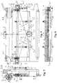
Fig.1 is a front view of a first embodiment of this invention (including C-C view, D-D view and E-E view inFig.2 ). -
Fig.2 is a right view of the first embodiment of this invention (including B-B view and F-F view inFig. 1 ). -
Fig.3 is an A-A view inFig.1 . -
Fig.4 is a front view of a second embodiment of this invention (including C-C view and D-D view inFig.5 ). -
Fig.5 is a right view of the second embodiment of this invention (including B-B view and E-E view inFig.4 ). -
Fig.6 is the A-A view inFig.4 . -
Fig.7 is a front view of a third embodiment of this invention (including C-C view, D-D view and E-E view inFig.8 ). -
Fig.8 is a right view of the third embodiment of this invention (including B-B view, F- F view and G-G view inFig.7 ). -
Fig.9 is the A-A view inFig.7 . -
Fig.10 is a front view ofcylinder head 51 inFig.7 . -
Fig.11 is a right view ofcylinder head 51 inFig.7 . -
Fig.12 is a front view ofnut 50 inFig.7 . -
Fig. 13 is a schematic illustrating working principle of this invention. -
Fig.14 is the A-A view inFig.13 . - A detailed description of embodiments in accordance with the present invention is provided hereinafter with reference to accompanying drawings.
- As shown in
Fig.1, Fig.2 and Fig. 3 , the first embodiment discloses a soft coiled material translation device used on a pillow type of packing machine. The soft coiled material translation device includesframe 1, left turningdevice 2,right turning device 3, left folding rod pair 4 and rightfolding rod pair 5.Left turning device 2 andright turning device 3 are symmetrically mounted on the left and the right sides offrame 1, respectively.Left turning device 2 andright turning device 3 can be turned on axis of turningcentre 6 onframe 1. Left folding rod pair 4 is mounted onleft turning device 2, and rightfolding rod pair 5 is mounted onright turning device 3.Left turning device 2 andright turning device 3 each includes turningseat 7, turning guide unit and turning regulating unit. Left folding rod pair 4 and rightfolding rod pair 5 are mounted on turningseats 7 ofleft turning device 2 andright turning device 3 respectively. Left folding rod pair 4 includesupper folding arm 4a andlower folding arm 4b; rightfolding rod pair 5 includesupper folding arm 5a andlower folding arm 5b; the working parts ofupper folding arm 4a,lower folding arm 4b,upper folding arm 5a andlower folding arm 5b are round bars. - The turning guide unit includes
slide 8 and turningslide guide 31 onframe 1, the turning regulating unit includes sector gears 9 and gears 10, and turningslide guide 31 is fixed onsector gear 9 with a parallel connection. Sector gears 9 ofleft turning device 2 andright turning device 3 are fixed on the left and right sides offrame 1 respectively, and circle centre ofsector gear 9 coincides with turningcentre 6.Gears 10 meshes with sector gears 9;gear shaft 11 ofgear 10 is mounted on turningseat 7; andknob 12 is mounted ongear shaft 11.Slide 8 is fixed on turningseat 7 viascrew 13, and has turningslide guide 31 having a concave. Turning slide guide 31 having a concave covers turningslide guide 31 having a convexity offrame 1, and circle centre of turningslide guide 31 andsector gear 9 respectively coincide with turningcentre 6. The turning regulating unit also includes screw 14 andknob 15. Screw 14 is fitted with a screw hole onslide 8; one end of screw 14touches frame 1, the other end of screw 14 is connected withknob 15.Upper folding arm 4a andupper folding arm 5a are mounted on left and right movingbeds 23 respectively. Left and right movingbeds 23 are mounted on left and right turning seats 7.Lower folding arm 4b andlower folding arm 5b are directly fixed on left and right turningseats 7 respectively,lower generating line 4c oflower folding arm 4b andlower generating line 5c oflower folding arm 5b each passes turningcentre 6. Movingbed 23 has a moving guide unit and a moving adjustment unit. The moving guide unit includes guidingslot 29,screw 30 andscrew 32. Guidingslot 29 is a straight slot and perpendicular to the axis oflower folding arm 4b orlower folding arm 5b.Screw 30 andscrew 32, passing guidingslot 29, are fitted with two screw holes on turningseat 7 respectively. The line throughscrew 30 andscrew 32 is perpendicular to the axis of thelower folding arm 4b orlower folding arm 5b. Movingbed 23 is mounted on turningseat 7, and straightly moves through guidingslot 29 alongscrew 30 andscrew 32. - The moving adjustment unit includes adjusting
shaft 34,screw 35 andscrew 36. Two ends of adjustingshaft 34 have internal threads with opposite rotation, and thread rotation ofscrew 35 is opposite to thread rotation ofscrew 36.Screw 35 and screw 36 are fitted with the internal threads at two ends of adjustingshaft 34 respectively.Screw 35 and screw 36 are mounted on turningseat 7 and movingbed 23 respectively, and axis of adjustingshaft 34,screw 35 and screw 36 are perpendicular to the axis of thelower folding arm 4b orlower folding arm 5b.Upper folding arm 4a andupper folding arm 5a are mounted on movingbed 23 viaswing pin roll 24 respectively. Each ofupper folding arm 4a andupper folding arm 5a has a swinging adjustment device. The swinging adjustment device includesscrew 37,knob 38 andspring 39.Screw 37 is fitted with screw hole on movingbed 23, and one end ofscrew 37 touches one side of tail ofupper folding arm 4a orupper folding arm 5a, andknob 38 is mounted on the other end of thescrew 37;spring 39 can be a compression spring, and one end ofspring 39touches moving bed 23, the other end ofspring 39 touches the other side of tail ofupper folding arm 4a orupper folding arm 5a. Drivingroll 25 andknife rest 27 are mounted onframe 1; cuttingknife 26 is mounted onknife rest 27. Drivingroll 25 is located in front ofupper folding arm 4a andupper folding arm 5a, and is replaced with a film driving roll of the packing machine. Cuttingknife 26 is located in middle of drivingroll 25. Steeringroll 25 is mounted onframe 1, and steeringroll 28 is located behindlower folding arm 4b andlower folding arm 5b. - As shown in
Fig.4 to Fig.6 , the second embodiment discloses a soft coiled material translation device used on a pillow type of packing machine. The soft coiled material translation device includesframe 1, left turningdevice 2,right turning device 3, left folding rod pair 4 and rightfolding rod pair 5.Left turning device 2 andright turning device 3 each includes turningseat 7, a turning guide unit and a turning regulating unit.Pin roll 16 is fixed onframe 1, turningseat 7 ofleft turning device 2 orright turning device 3 is mounted onpin roll 16 via a shaft hole, and the axis ofpin roll 16 is turningcentre 6 ofleft turning device 2 andright turning device 3. Left folding rod pair 4 is mounted onleft turning device 2, and rightfolding rod pair 5 is mounted onright turning device 3. Left folding rod pair 4 and rightfolding rod pair 5 are respectively mounted on turningseats 7 ofleft turning device 2 andright turning device 3. Left folding rod pair 4 includesupper folding arm 4a andlower folding arm 4b; rightfolding rod pair 5 includesupper folding arm 5a andlower folding arm 5b; working part ofupper folding arm 4a,lower folding arm 4b,upper folding arm 5a andlower folding arm 5b are round bars. - The turning guide unit includes
pin roll 16 offrame 1, shaft holes on turningseats 7 ofleft turning device 2 andright turning device 3. The turning regulating unit includes adjustingshaft 19,screw 20,screw 21 andpin roll 22.Arc slot 17 is fixed onframe 1, and circle centre ofarc slot 17 coincides with turningcentre 6. The middle part ofpin roll 18 is located inarc slot 17, and one end ofpin roll 18 is fixed on turningseat 7, the other end ofpin roll 18 is connected withscrew 21. One end ofpin roll 22 is fixed onframe 1; the other end ofpin roll 22 is connected withscrew 20. Two ends of adjustingshaft 19 have internal threads with opposite rotation; thread rotation ofscrew 20 is opposite to thread rotation ofscrew 21. The internal threads of adjustingshaft 19 are fitted withscrew 20 and screw 21 respectively.Lower folding arm 4b andlower folding arm 5b are directly mounted on left turningseat 7 and right turningseat 7 respectively, andlower generating line 4c oflower folding arm 4b andlower generating line 5c oflower folding arm 5b each passes turningcentre 6.Upper folding arm 4a is mounted on left turningseat 7 viaswing pin roll 24, andupper folding arm 4a has a swinging adjustment device.Upper folding arm 5a is mounted on movingbed 23 which is mounted onright turning seat 7. - Moving
bed 23 has a moving guide unit and a moving adjustment unit. The moving guide unit includesdovetail guide 43 on movingbed 23 anddovetail slot 44 on turningseat 7.Dovetail guide 43 anddovetail slot 44 are fitted with each other, movingbed 23 is mounted onright turning seat 7, and movingbed 23 moves straightly on right turningseat 7 viadovetail guide 43 anddovetail slot 44.Dovetail guide 43 anddovetail slot 44 are perpendicular to the axis oflower folding arm 4b. The moving adjustment unit includes adjustingshaft 45,screw 46 andscrew 47. Two ends of adjustingshaft 45 have internal threads with opposite rotation; thread rotation ofscrew 46 is opposite to thread rotation ofscrew 47.Screw 46 and screw 47 are fitted with the internal threads of two ends of adjustingshaft 45 respectively.Screw 46 and screw 47 are mounted onright turning seat 7 and movingbed 23 respectively. The axis of adjustingshaft 45,screw 46 and screw 47 are perpendicular to the axis oflower folding arm 5b.Upper folding arm 5a is mounted on movingbed 23 viaswing pin roll 24, andupper folding arm 5a has a swinging adjustment device. Each of winging controlling devices ofupper folding arm 4a andupper folding arm 5a includesscrew 40,knob 41 andnut 42.Screw 40 ofupper folding arm 4a is mounted on left turningseat 7, andknob 41 is mounted on one end ofscrew 40.Nut 42 ofupper folding arm 4a is in the slotted hole ofupper folding arm 4a, andnut 42 is fitted withscrew 40.Nut 40 ofupper folding arm 5a is mounted on movingbed 23, andknob 41 is mounted on one end ofnut 40.Nut 42 ofupper folding arm 5a is in the slotted hole ofupper folding arm 5a, and is fitted withscrew 40. Drivingroll 25 andknife rest 27 are mounted onframe 1; cuttingknife 26 is mounted onknife rest 27. Drivingroll 25 is located in front ofupper folding arm 4a andupper folding arm 5a. Cuttingknife 26 is located in the middle of drivingroll 25. Steeringroll 25 is mounted onframe 1; steeringroll 28 is located behindlower folding arm 4b andlower folding arm 5b. - As shown in
Fig.7 to Fig.12 , the third embodiment discloses a soft coiled material translation device used on a pillow type of packing machine. The soft coiled material translation device includesframe 1, left turningdevice 2,right turning device 3, left folding rod pair 4 and rightfolding rod pair 5. The third embodiment is same as the first embodiment except that locations of turningslide guide 31, the moving adjustment unit and the swinging adjustment device. Turningslide guide 31 is set on contact surface betweenframe 1 and turningseat 7. The moving adjustment unit includesscrew 48 andknob 49, andknob 49 is fixed on one end ofscrew 48. Two ends ofscrew 48 have external threads with opposite rotation, turningseat 7 and movingbed 23 respectively have internal threads with opposite rotation, and the external threads onscrew 48 are fitted with internal threads of turningseat 7 and movingbed 23 respectively. The swinging adjustment device includesnut 50,cylinder head 51,screw 52 andknob 53.Screw 52 is mounted on movingbed 23, andknob 53 is mounted on one end ofknob 53.Nut 50 is fitted withscrew 52.Cylinder head 51 is at the tail ofupper folding arm 4a andupper folding arm 5a, and there iscylinder face 54 oncylinder head 51. There is a square-shapedslot 55, andcylinder head 51 is located in square-shapedslot 55. - The working process of the above three embodiments is shown in
Fig. 13 and Fig.14 . A roll ofplastic film 56 of a pillow type of packing machine is cut by cuttingknife 26 intofilm belt 57 andfilm belt 58 in parallel. After turned back via left folding rod pair 4 and rightfolding rod pair 5,film belt 57 andfilm belt 58 are apart from each other, and the distance betweenfilm belt 57 andfilm belt 58, L, is increased, andfilm belt 57 andfilm belt 58 are still kept parallel with each other. Finally,film belt 57 andfilm belt 58 are put away by steeringroll 28, and are processed in the next packing processes, such as bag making and forming, longitudinal sealing, and transverse sealing and cutting. Two rows of articles may be packed byfilm belt 57 andfilm belt 58 simultaneously. The turning regulating unit adjusts the angle α through whichupper folding arm 4a andlower folding arm 4b rotate ,andupper folding arm 5a andlower folding arm 5b rotate, then the distance betweenfilm belt 57 andfilm belt 58 ,L, can be adjusted. The cutting error caused by the fact thatfilm belt 57 andfilm belt 58 are inconsistently prolonged in subsequent processes can be adjusted by adjusting, via the moving adjustment unit, the distance between upperfolding arm 4a andlower folding arm 4b, or the distance between upperfolding arm 5a andlower folding arm 5b. The tension of the two sides of each offilm belts folding arm 4a andlower folding arm 4b, or the angle between upperfolding arm 5a andlower folding arm 5b.
Claims (8)
- A soft coiled material translation device, comprising
a frame (1);
a left turning device (2) and a right turning device (3) mounted on the frame; and
a left folding rod pair (4) mounted on the left turning device (2), a right folding rod pair (5) mounted on the right turning device (3),
wherein the left folding rod pair (4) comprises a left upper folding arm (4a) and a left lower folding arm (4b); and the right folding rod pair (5) comprises a right upper folding arm (5a) and a right lower folding arm (5b);
characterized in that the left turning device (2) is adapted to be turned around the axis of a turning centre (6) to adjust an angle between the folding arms of the left folding rod pair (4) and the direction in which the soft coiled material goes ahead, the right turning device (3) is adapted to be turned around the axis of the turning centre (6) to adjust another angle between the folding arms of the right folding rod pair (5) and the direction in which the soft coiled material goes ahead, and each of the left turning device (2) and the right turning device (3) comprises a turning seat (7), a turning guide unit and a turning regulating unit;
wherein the turning seat (7) is connected with the frame (1) via a revolving pair, and the turning seat (7) makes a swing on the frame (1); the turning guide unit is configured to guide the turning seat (7), and make the turning seat (7) swing around the turning centre (6) on the frame (1); the turning regulating unit is configured to adjust a swing angle through which the turning seat (7) swings around the turning centre (6);
wherein the left folding rod pair (4) is mounted on the turning seat (7) of the left turning device (2), and the right folding rod pair (5) is mounted on the turning seat (7) of the right turning device (3), the soft coiled material is turned back by the lower folding arm of each of the left folding rod pair (4) and the right folding rod pair (5) first, then is turned back again by the upper folding arm of each of the left folding rod pair (4) and the right folding rod pair (5), and goes ahead again. - The soft coiled material translation device of Claim 1, wherein the turning guide unit comprises a slide (8) and a turning slide guide (31) on the frame (1); and
the turning regulating unit comprises a sector gear (9) and a gear (10); the sector gear (9) of the left turning device (2) is fixed on left side of the frame (1), the sector gear (9) of the right turning device (3) is fixed on right side of the frame (1); a circle centre of the sector gear (9) coincides with the turning centre (6); the gear (10) meshes with the sector gear (9), a gear shaft (11) of the gear (10) is mounted on the turning seat (7); a knob (12) is mounted on the gear shaft (11); the slide (8) is fixed on the turning seat (7), and is slideably fitted with the turning slide guide (31), and the circle centre of the turning slide guide (31) coincides with the turning centre (6). - The soft coiled material translation device of Claim 2, wherein the turning regulating unit further comprises a first screw (14) and a knob (15); the first screw (14) is fitted with a screw hole on the slide (8), and one end of the first screw (14) touches the frame (1), the other end of the first screw (14) is connected with the knob (15).
- The soft coiled material translation device of Claim 1, wherein the turning guide unit comprises a first pin roll (16) on the frame (1), and shaft holes on the turning seats (7) of the left turning device (2) and the right turning device (3),the turning seats(7) of the left turning device (2) and the right turning device (3) are mounted on the first pin roll (16) via the shaft holes, and an axis of the first pin roll (16) is the turning centre (6) of the left turning device (2) and the right turning device (3); and
the turning regulating unit comprises an arc slot (17), a second pin roll (18), an adjusting shaft (19), a second screw (20), a third screw (21) and a third pin roll (22); the arc slot (17) is mounted on the frame (1), and the circle centre of the arc slot (17) coincides with the turning centre (6); a middle part of the second pin roll (18) is located in the arc slot (17), one end of the second pin roll (18) is fixed on the turning seat (7), and the other end of the second pin roll (18) is connected with the third screw (21); one end of the third pin roll (22) is fixed on the frame (1), and the other end of the third pin roll (22) is connected with the second screw (20); two ends of the adjusting shaft (19) have internal threads with opposite rotation, thread rotation of the second screw (20) is opposite to thread rotation of the third screw (21), and the internal threads at the two ends of the adjusting shaft (19) are fitted with the second screw (20) and the third screw (21) respectively. - The soft coiled material translation device of Claim 1, wherein at least one of the left upper folding arm (4a) and the right upper folding arm (5a) is mounted on a moving bed (23), and the moving bed (23) is mounted on the turning seat (7); the moving bed (23) comprises a moving guide unit and a moving adjustment unit.
- The soft coiled material translation device of Claim 5, wherein the left upper folding arm (4a) and the right upper folding arm (5a) are mounted on the moving bed (23) via a swing pin roll (24) respectively, and the left upper folding arm (4a) and the right upper folding arm (5a) each has a swinging adjustment device.
- The soft coiled material translation device of Claim 1, wherein the frame (1) has a driving roll (25) and a knife rest (27), a cutting knife (26) is mounted on the knife rest (27), the driving roll (25) is located in front of the left upper folding arm (4a) and the right upper folding arm (5a), the cutting knife (26) is located in the middle of the driving roll (25).
- The soft coiled material translation device of Claim 7, wherein a steering roll (28) is mounted on the frame (1), the steering roll (28) is located behind the left lower folding arm (4b) and the right lower folding arm (5b).
Applications Claiming Priority (2)
| Application Number | Priority Date | Filing Date | Title |
|---|---|---|---|
| CNB2005100549217A CN100363246C (en) | 2005-03-18 | 2005-03-18 | Soft roll material translation device |
| PCT/CN2006/000353 WO2006097034A1 (en) | 2005-03-18 | 2006-03-09 | A soft roll material-translation device |
Publications (3)
| Publication Number | Publication Date |
|---|---|
| EP1864929A1 EP1864929A1 (en) | 2007-12-12 |
| EP1864929A4 EP1864929A4 (en) | 2011-03-30 |
| EP1864929B1 true EP1864929B1 (en) | 2018-10-10 |
Family
ID=34876729
Family Applications (1)
| Application Number | Title | Priority Date | Filing Date |
|---|---|---|---|
| EP06722018.6A Active EP1864929B1 (en) | 2005-03-18 | 2006-03-09 | A soft roll material-translation device |
Country Status (5)
| Country | Link |
|---|---|
| US (1) | US7717840B2 (en) |
| EP (1) | EP1864929B1 (en) |
| JP (1) | JP5081806B2 (en) |
| CN (1) | CN100363246C (en) |
| WO (1) | WO2006097034A1 (en) |
Families Citing this family (4)
| Publication number | Priority date | Publication date | Assignee | Title |
|---|---|---|---|---|
| CN101575797B (en) * | 2009-06-11 | 2011-04-13 | 杭州天堂伞业集团有限公司 | Semi-automatic double-pole umbrella fabric pressure cutting machine |
| CN102803109B (en) * | 2010-02-12 | 2015-04-22 | 株式会社尼康 | Processing device and transfer device for a strip-shaped sheet substrate |
| CN105502068B (en) * | 2016-01-25 | 2017-11-07 | 东莞市新望包装机械有限公司 | A kind of full-automatic banding machine |
| CN106735103B (en) * | 2016-11-30 | 2018-10-19 | 天能电池(芜湖)有限公司 | Battery grid band is oriented to wrap-up anyhow |
Citations (1)
| Publication number | Priority date | Publication date | Assignee | Title |
|---|---|---|---|---|
| US2990989A (en) * | 1959-01-26 | 1961-07-04 | Schjeldahl Co G T | Compensator for web sheet |
Family Cites Families (28)
| Publication number | Priority date | Publication date | Assignee | Title |
|---|---|---|---|---|
| US2162230A (en) * | 1938-02-05 | 1939-06-13 | Ivers Lee Co | Alignment controlled packaging machine |
| US2331030A (en) * | 1941-03-04 | 1943-10-05 | Hess | Web aligning apparatus |
| US2807465A (en) * | 1953-05-11 | 1957-09-24 | E G Staude Mfg Company Inc | Side guide tension for webs |
| US2989265A (en) * | 1960-05-31 | 1961-06-20 | Ampex | Tape guiding system |
| US3451187A (en) * | 1966-09-27 | 1969-06-24 | Medalist Ind Inc | Packaging machine |
| FR1537697A (en) * | 1967-03-03 | 1968-08-30 | Comp Generale Electricite | Thin strip cutting machine |
| JPS4616930Y1 (en) * | 1968-05-16 | 1971-06-12 | ||
| US3606120A (en) * | 1969-06-23 | 1971-09-20 | Turbo Machine Co | Continuous band width controller and band director |
| US3682362A (en) * | 1971-03-15 | 1972-08-08 | Rockford Servo Corp | Web edge sensing and guiding apparatus |
| US4085560A (en) * | 1976-10-27 | 1978-04-25 | Wrap-Ade Machine Company, Inc. | Apparatus and method of forming covers for flexible commodity-containing packages |
| US4107900A (en) * | 1977-06-03 | 1978-08-22 | Shinjiro Izumi | Forming and filling bags of synthetic plastics materials |
| DE3203160A1 (en) * | 1981-11-12 | 1983-05-19 | A. Monforts GmbH & Co, 4050 Mönchengladbach | Variable-tension device |
| US4697755A (en) * | 1984-08-27 | 1987-10-06 | Hiroshi Kataoka | Rewinder with slitter |
| US5072571A (en) * | 1990-02-26 | 1991-12-17 | Zip-Pak Incorporated | Zippered film plural sheet strip guide system and method for zippered film for form, fill and seal package making machines |
| US5174096A (en) * | 1990-10-05 | 1992-12-29 | Ishida Scales Mfg. Co., Ltd. | Form-fill-seal type packaging machine |
| US5558263A (en) * | 1994-07-26 | 1996-09-24 | Eastman Kodak Company | Apparatus and method for non-contact active tensioning and steering of moving webs |
| US5823461A (en) * | 1997-03-10 | 1998-10-20 | Faustel, Inc. | No-fold back splicer with electrostatic web transfer device |
| JP2943101B2 (en) * | 1997-05-07 | 1999-08-30 | 株式会社ミヤコシ | Turn bar device |
| JP3338377B2 (en) * | 1998-06-26 | 2002-10-28 | 三光機械株式会社 | Feeding direction change mechanism for packaging film for multiple automatic packaging machines |
| US6264130B1 (en) | 1999-09-13 | 2001-07-24 | Faustel, Inc. | Duplex web roll winding and splicing apparatus |
| CN2444916Y (en) | 2000-11-01 | 2001-08-29 | 曹立宏 | Unwinding device for film cutting machine |
| DE10059004A1 (en) * | 2000-11-28 | 2002-07-25 | Nexpress Solutions Llc | Device for generating an offset of transported flexible flat material |
| JP2003035937A (en) * | 2001-05-16 | 2003-02-07 | Fuji Photo Film Co Ltd | Mechanism for truing up edge in width direction |
| CN1321868C (en) | 2002-02-06 | 2007-06-20 | 株式会社片冈机械制作所 | Sheet cutting coiling apparatus |
| DE10234674B4 (en) * | 2002-07-30 | 2010-04-29 | Wifag Maschinenfabrik Ag | Bahnspreizvorrichtung |
| US6827087B2 (en) * | 2002-11-19 | 2004-12-07 | Joseph T. Wanna | Cigarette with burn rate modification |
| CN2612611Y (en) | 2003-05-12 | 2004-04-21 | 达和机械(昆山)有限公司 | Auto-paster for pillow type packing machine |
| CN2808844Y (en) * | 2005-03-20 | 2006-08-23 | 李法岗 | Flexible coiled material level-shifting device |
-
2005
- 2005-03-18 CN CNB2005100549217A patent/CN100363246C/en active Active
-
2006
- 2006-03-09 EP EP06722018.6A patent/EP1864929B1/en active Active
- 2006-03-09 WO PCT/CN2006/000353 patent/WO2006097034A1/en not_active Application Discontinuation
- 2006-03-09 US US11/886,639 patent/US7717840B2/en active Active
- 2006-03-09 JP JP2008501140A patent/JP5081806B2/en active Active
Patent Citations (1)
| Publication number | Priority date | Publication date | Assignee | Title |
|---|---|---|---|---|
| US2990989A (en) * | 1959-01-26 | 1961-07-04 | Schjeldahl Co G T | Compensator for web sheet |
Also Published As
| Publication number | Publication date |
|---|---|
| WO2006097034A1 (en) | 2006-09-21 |
| EP1864929A1 (en) | 2007-12-12 |
| JP5081806B2 (en) | 2012-11-28 |
| EP1864929A4 (en) | 2011-03-30 |
| US20090029839A1 (en) | 2009-01-29 |
| JP2008532865A (en) | 2008-08-21 |
| CN1648024A (en) | 2005-08-03 |
| US7717840B2 (en) | 2010-05-18 |
| CN100363246C (en) | 2008-01-23 |
Similar Documents
| Publication | Publication Date | Title |
|---|---|---|
| EP1480790B1 (en) | Soft goods slitter and feed system for quilting | |
| US7673575B2 (en) | Soft goods slitter and feed system for quilting | |
| US7669540B2 (en) | Soft goods slitter and feed system for quilting | |
| JP3382196B2 (en) | Web paper position adjustment device | |
| EP1864929B1 (en) | A soft roll material-translation device | |
| WO2007012739A8 (en) | Device for longitudinally cutting a web of continuously moving material to form a strip with variable longitudinal profile | |
| KR101129051B1 (en) | Cutting assembly and cutting machine for cutting uncut film of adhesive tape and method for manufacturing adhesive tape with cut area by using the same | |
| JPH04226265A (en) | Vertical folding device | |
| JP3416852B2 (en) | Method and apparatus for manufacturing pocket coil spring | |
| JPH09136758A (en) | Adjusting mechanism of crosswise prick punch machine | |
| CN112758746B (en) | Guide device capable of spatially staggered conveying and non-woven fabric forming and processing mechanism | |
| CN2808844Y (en) | Flexible coiled material level-shifting device | |
| US8104414B2 (en) | Apparatus and method for producing large stitched products | |
| JP7411985B2 (en) | slitter | |
| JP7386512B2 (en) | Slitter blade positioning mechanism | |
| JP2630754B2 (en) | Drive device for drag roller on former | |
| RU2028268C1 (en) | Winding spreader | |
| CN118373240A (en) | Connect paper cutting device and connect paper machine | |
| JPH07137925A (en) | Insertion device for sheet-like material between slicing materials | |
| JPH02123060A (en) | Web feeder | |
| JPH08119497A (en) | Sheet cutter device | |
| JPH07179270A (en) | Duplex winding preventive device in wire rod alignment winder | |
| JPH07215585A (en) | Wire rod aligning winding machine | |
| FR2632290A1 (en) | Method of producing beams of filamentary textile elements, application to the production of a fabric by knitting these elements, means implemented and products obtained | |
| JPH1110587A (en) | Sliced meat folding device for block meat slicer |
Legal Events
| Date | Code | Title | Description |
|---|---|---|---|
| PUAI | Public reference made under article 153(3) epc to a published international application that has entered the european phase |
Free format text: ORIGINAL CODE: 0009012 |
|
| 17P | Request for examination filed |
Effective date: 20071017 |
|
| AK | Designated contracting states |
Kind code of ref document: A1 Designated state(s): AT BE BG CH CY CZ DE DK EE ES FI FR GB GR HU IE IS IT LI LT LU LV MC NL PL PT RO SE SI SK TR |
|
| DAX | Request for extension of the european patent (deleted) | ||
| A4 | Supplementary search report drawn up and despatched |
Effective date: 20110228 |
|
| 17Q | First examination report despatched |
Effective date: 20160627 |
|
| STAA | Information on the status of an ep patent application or granted ep patent |
Free format text: STATUS: EXAMINATION IS IN PROGRESS |
|
| GRAP | Despatch of communication of intention to grant a patent |
Free format text: ORIGINAL CODE: EPIDOSNIGR1 |
|
| STAA | Information on the status of an ep patent application or granted ep patent |
Free format text: STATUS: GRANT OF PATENT IS INTENDED |
|
| INTG | Intention to grant announced |
Effective date: 20180423 |
|
| GRAS | Grant fee paid |
Free format text: ORIGINAL CODE: EPIDOSNIGR3 |
|
| GRAA | (expected) grant |
Free format text: ORIGINAL CODE: 0009210 |
|
| STAA | Information on the status of an ep patent application or granted ep patent |
Free format text: STATUS: THE PATENT HAS BEEN GRANTED |
|
| AK | Designated contracting states |
Kind code of ref document: B1 Designated state(s): AT BE BG CH CY CZ DE DK EE ES FI FR GB GR HU IE IS IT LI LT LU LV MC NL PL PT RO SE SI SK TR |
|
| REG | Reference to a national code |
Ref country code: GB Ref legal event code: FG4D |
|
| REG | Reference to a national code |
Ref country code: CH Ref legal event code: EP Ref country code: AT Ref legal event code: REF Ref document number: 1050971 Country of ref document: AT Kind code of ref document: T Effective date: 20181015 |
|
| REG | Reference to a national code |
Ref country code: IE Ref legal event code: FG4D Ref country code: DE Ref legal event code: R096 Ref document number: 602006056543 Country of ref document: DE |
|
| REG | Reference to a national code |
Ref country code: SE Ref legal event code: TRGR |
|
| REG | Reference to a national code |
Ref country code: NL Ref legal event code: MP Effective date: 20181010 |
|
| REG | Reference to a national code |
Ref country code: LT Ref legal event code: MG4D |
|
| REG | Reference to a national code |
Ref country code: AT Ref legal event code: MK05 Ref document number: 1050971 Country of ref document: AT Kind code of ref document: T Effective date: 20181010 |
|
| PG25 | Lapsed in a contracting state [announced via postgrant information from national office to epo] |
Ref country code: NL Free format text: LAPSE BECAUSE OF FAILURE TO SUBMIT A TRANSLATION OF THE DESCRIPTION OR TO PAY THE FEE WITHIN THE PRESCRIBED TIME-LIMIT Effective date: 20181010 |
|
| PG25 | Lapsed in a contracting state [announced via postgrant information from national office to epo] |
Ref country code: FI Free format text: LAPSE BECAUSE OF FAILURE TO SUBMIT A TRANSLATION OF THE DESCRIPTION OR TO PAY THE FEE WITHIN THE PRESCRIBED TIME-LIMIT Effective date: 20181010 Ref country code: LT Free format text: LAPSE BECAUSE OF FAILURE TO SUBMIT A TRANSLATION OF THE DESCRIPTION OR TO PAY THE FEE WITHIN THE PRESCRIBED TIME-LIMIT Effective date: 20181010 Ref country code: PL Free format text: LAPSE BECAUSE OF FAILURE TO SUBMIT A TRANSLATION OF THE DESCRIPTION OR TO PAY THE FEE WITHIN THE PRESCRIBED TIME-LIMIT Effective date: 20181010 Ref country code: BG Free format text: LAPSE BECAUSE OF FAILURE TO SUBMIT A TRANSLATION OF THE DESCRIPTION OR TO PAY THE FEE WITHIN THE PRESCRIBED TIME-LIMIT Effective date: 20190110 Ref country code: LV Free format text: LAPSE BECAUSE OF FAILURE TO SUBMIT A TRANSLATION OF THE DESCRIPTION OR TO PAY THE FEE WITHIN THE PRESCRIBED TIME-LIMIT Effective date: 20181010 Ref country code: ES Free format text: LAPSE BECAUSE OF FAILURE TO SUBMIT A TRANSLATION OF THE DESCRIPTION OR TO PAY THE FEE WITHIN THE PRESCRIBED TIME-LIMIT Effective date: 20181010 Ref country code: AT Free format text: LAPSE BECAUSE OF FAILURE TO SUBMIT A TRANSLATION OF THE DESCRIPTION OR TO PAY THE FEE WITHIN THE PRESCRIBED TIME-LIMIT Effective date: 20181010 Ref country code: IS Free format text: LAPSE BECAUSE OF FAILURE TO SUBMIT A TRANSLATION OF THE DESCRIPTION OR TO PAY THE FEE WITHIN THE PRESCRIBED TIME-LIMIT Effective date: 20190210 |
|
| PG25 | Lapsed in a contracting state [announced via postgrant information from national office to epo] |
Ref country code: PT Free format text: LAPSE BECAUSE OF FAILURE TO SUBMIT A TRANSLATION OF THE DESCRIPTION OR TO PAY THE FEE WITHIN THE PRESCRIBED TIME-LIMIT Effective date: 20190210 Ref country code: GR Free format text: LAPSE BECAUSE OF FAILURE TO SUBMIT A TRANSLATION OF THE DESCRIPTION OR TO PAY THE FEE WITHIN THE PRESCRIBED TIME-LIMIT Effective date: 20190111 |
|
| REG | Reference to a national code |
Ref country code: DE Ref legal event code: R097 Ref document number: 602006056543 Country of ref document: DE |
|
| PG25 | Lapsed in a contracting state [announced via postgrant information from national office to epo] |
Ref country code: CZ Free format text: LAPSE BECAUSE OF FAILURE TO SUBMIT A TRANSLATION OF THE DESCRIPTION OR TO PAY THE FEE WITHIN THE PRESCRIBED TIME-LIMIT Effective date: 20181010 Ref country code: DK Free format text: LAPSE BECAUSE OF FAILURE TO SUBMIT A TRANSLATION OF THE DESCRIPTION OR TO PAY THE FEE WITHIN THE PRESCRIBED TIME-LIMIT Effective date: 20181010 |
|
| PLBE | No opposition filed within time limit |
Free format text: ORIGINAL CODE: 0009261 |
|
| STAA | Information on the status of an ep patent application or granted ep patent |
Free format text: STATUS: NO OPPOSITION FILED WITHIN TIME LIMIT |
|
| PG25 | Lapsed in a contracting state [announced via postgrant information from national office to epo] |
Ref country code: SK Free format text: LAPSE BECAUSE OF FAILURE TO SUBMIT A TRANSLATION OF THE DESCRIPTION OR TO PAY THE FEE WITHIN THE PRESCRIBED TIME-LIMIT Effective date: 20181010 Ref country code: EE Free format text: LAPSE BECAUSE OF FAILURE TO SUBMIT A TRANSLATION OF THE DESCRIPTION OR TO PAY THE FEE WITHIN THE PRESCRIBED TIME-LIMIT Effective date: 20181010 Ref country code: RO Free format text: LAPSE BECAUSE OF FAILURE TO SUBMIT A TRANSLATION OF THE DESCRIPTION OR TO PAY THE FEE WITHIN THE PRESCRIBED TIME-LIMIT Effective date: 20181010 |
|
| 26N | No opposition filed |
Effective date: 20190711 |
|
| PG25 | Lapsed in a contracting state [announced via postgrant information from national office to epo] |
Ref country code: MC Free format text: LAPSE BECAUSE OF FAILURE TO SUBMIT A TRANSLATION OF THE DESCRIPTION OR TO PAY THE FEE WITHIN THE PRESCRIBED TIME-LIMIT Effective date: 20181010 Ref country code: SI Free format text: LAPSE BECAUSE OF FAILURE TO SUBMIT A TRANSLATION OF THE DESCRIPTION OR TO PAY THE FEE WITHIN THE PRESCRIBED TIME-LIMIT Effective date: 20181010 |
|
| PG25 | Lapsed in a contracting state [announced via postgrant information from national office to epo] |
Ref country code: LU Free format text: LAPSE BECAUSE OF NON-PAYMENT OF DUE FEES Effective date: 20190309 |
|
| REG | Reference to a national code |
Ref country code: BE Ref legal event code: MM Effective date: 20190331 |
|
| PG25 | Lapsed in a contracting state [announced via postgrant information from national office to epo] |
Ref country code: IE Free format text: LAPSE BECAUSE OF NON-PAYMENT OF DUE FEES Effective date: 20190309 |
|
| PG25 | Lapsed in a contracting state [announced via postgrant information from national office to epo] |
Ref country code: BE Free format text: LAPSE BECAUSE OF NON-PAYMENT OF DUE FEES Effective date: 20190331 |
|
| PG25 | Lapsed in a contracting state [announced via postgrant information from national office to epo] |
Ref country code: TR Free format text: LAPSE BECAUSE OF FAILURE TO SUBMIT A TRANSLATION OF THE DESCRIPTION OR TO PAY THE FEE WITHIN THE PRESCRIBED TIME-LIMIT Effective date: 20181010 |
|
| PG25 | Lapsed in a contracting state [announced via postgrant information from national office to epo] |
Ref country code: CY Free format text: LAPSE BECAUSE OF FAILURE TO SUBMIT A TRANSLATION OF THE DESCRIPTION OR TO PAY THE FEE WITHIN THE PRESCRIBED TIME-LIMIT Effective date: 20181010 |
|
| PG25 | Lapsed in a contracting state [announced via postgrant information from national office to epo] |
Ref country code: HU Free format text: LAPSE BECAUSE OF FAILURE TO SUBMIT A TRANSLATION OF THE DESCRIPTION OR TO PAY THE FEE WITHIN THE PRESCRIBED TIME-LIMIT; INVALID AB INITIO Effective date: 20060309 |
|
| PGFP | Annual fee paid to national office [announced via postgrant information from national office to epo] |
Ref country code: DE Payment date: 20240321 Year of fee payment: 19 Ref country code: GB Payment date: 20240304 Year of fee payment: 19 |
|
| PGFP | Annual fee paid to national office [announced via postgrant information from national office to epo] |
Ref country code: SE Payment date: 20240226 Year of fee payment: 19 Ref country code: IT Payment date: 20240329 Year of fee payment: 19 Ref country code: FR Payment date: 20240223 Year of fee payment: 19 |
|
| PGFP | Annual fee paid to national office [announced via postgrant information from national office to epo] |
Ref country code: CH Payment date: 20240401 Year of fee payment: 19 |