EP1864927A2 - Plate feeding apparatus and plate feeding method - Google Patents
Plate feeding apparatus and plate feeding method Download PDFInfo
- Publication number
- EP1864927A2 EP1864927A2 EP07010709A EP07010709A EP1864927A2 EP 1864927 A2 EP1864927 A2 EP 1864927A2 EP 07010709 A EP07010709 A EP 07010709A EP 07010709 A EP07010709 A EP 07010709A EP 1864927 A2 EP1864927 A2 EP 1864927A2
- Authority
- EP
- European Patent Office
- Prior art keywords
- plate
- unit
- moving
- nip rollers
- plates
- Prior art date
- Legal status (The legal status is an assumption and is not a legal conclusion. Google has not performed a legal analysis and makes no representation as to the accuracy of the status listed.)
- Granted
Links
Images





Classifications
-
- B—PERFORMING OPERATIONS; TRANSPORTING
- B65—CONVEYING; PACKING; STORING; HANDLING THIN OR FILAMENTARY MATERIAL
- B65H—HANDLING THIN OR FILAMENTARY MATERIAL, e.g. SHEETS, WEBS, CABLES
- B65H3/00—Separating articles from piles
- B65H3/08—Separating articles from piles using pneumatic force
- B65H3/0808—Suction grippers
- B65H3/0816—Suction grippers separating from the top of pile
- B65H3/0825—Suction grippers separating from the top of pile and acting on the rear part of the articles relatively to the final separating direction
-
- B—PERFORMING OPERATIONS; TRANSPORTING
- B65—CONVEYING; PACKING; STORING; HANDLING THIN OR FILAMENTARY MATERIAL
- B65H—HANDLING THIN OR FILAMENTARY MATERIAL, e.g. SHEETS, WEBS, CABLES
- B65H2301/00—Handling processes for sheets or webs
- B65H2301/30—Orientation, displacement, position of the handled material
- B65H2301/33—Modifying, selecting, changing orientation
- B65H2301/332—Turning, overturning
- B65H2301/3321—Turning, overturning kinetic therefor
- B65H2301/33214—Turning, overturning kinetic therefor about an axis perpendicular to the direction of displacement and parallel to the surface of material
-
- B—PERFORMING OPERATIONS; TRANSPORTING
- B65—CONVEYING; PACKING; STORING; HANDLING THIN OR FILAMENTARY MATERIAL
- B65H—HANDLING THIN OR FILAMENTARY MATERIAL, e.g. SHEETS, WEBS, CABLES
- B65H2701/00—Handled material; Storage means
- B65H2701/10—Handled articles or webs
- B65H2701/19—Specific article or web
- B65H2701/1928—Printing plate
Definitions
- This invention relates to a plate feeding apparatus for transporting stacked printing plates in order from an uppermost plate, and in an inverted state, to a plate takeout unit such as nip rollers.
- Japanese Unexamined Patent Publication No. 2000-247489 discloses a plate feeding apparatus for transporting printing plates, in an inverted state, to a plate takeout unit.
- a suction point at a leading end of each plate sucked and held by suction pads is moved to coincide with a cycloid formed when a circle having a radius equal to the turning radius of the suction point rolls over the plate surface. Subsequently, the leading end of the plate is pinched by the plate takeout unit.
- Such a plate feeding apparatus that transports printing plates, in an inverted state, to the plate takeout unit has an advantage of transporting the plates reliably without occupying a large floor space even when transporting relatively large plates.
- plates are usually stacked with end edges aligned by a stopper. Then, with the plate feeding apparatus that transports the plates, in an inverted state, to the plate takeout unit, when a distance from a plate storage unit to the plate takeout unit is small for the size of the plates, the rear end of a plate will thrust itself in between the end edges of the plates stacked and the stopper, making it impossible to transport the plate properly.
- the object of this invention is to provide a plate feeding apparatus and a plate feeding method which can transport plates reliably without enlarging the apparatus.
- a plate feeding apparatus for transporting plates loaded therein, in order from an uppermost plate, while inverting the plates, toward a plate takeout unit that holds and takes out the plate
- the apparatus comprising a storage unit for storing a plurality of plates with end edges aligned by a stopper; a moving unit movable along surfaces of the plates stored in the storage unit; a suction unit disposed at a distal end of an arm swingable about the moving unit for sucking and holding an upper surface adjacent an end edge, remote from the plate takeout unit, of each of the plates stored in the storage unit; a moving mechanism for moving the moving unit along the surfaces of the plates stored in the storage unit, from a position remote from the plate takeout unit toward the plate takeout unit, and for swinging the arm about the moving unit, thereby moving the suction unit to invert a portion adjacent the end edge of each plate sucked and held by the suction unit, and subsequently to reach a position for each plate to be held by the plate take
- Such plate feeding apparatus can transport plates reliably without enlarging the apparatus.
- the plate feeding apparatus includes a pressing member moving device.
- the pressing member can, in a selected position along the surfaces of the plates stored, press a portion of an inner peripheral surface of each plate curved as it is turned back. It is therefore possible to perform properly even when the position of the pressing member pressing plates is changed to handle plates of different sizes.
- a plate feeding method for transporting plates stored in a storage unit with end edges of the plates aligned by a stopper, in order from an uppermost plate, while inverting the plates, to nip rollers, the method comprising a suction-holding step for causing a suction unit to suck and hold an upper surface adjacent an end edge, remote from the nip rollers, of each of the plates stored in the storage unit; a moving step, while swinging the suction unit about a moving unit, for moving the moving unit along the surfaces of the plates stored in the storage unit, from a position remote from the nip rollers toward the nip rollers, thereby inverting a portion adjacent the end edge of each plate sucked and held by the suction unit, and subsequently moving the end edge of each plate to a position to be pinched by the nip rollers; a pinching step for causing the nip rollers to pinch the end edge of each plate having been inverted
- FIG. 1 is a perspective view of an image recording system having a plate feeding apparatus according to this invention.
- Fig. 2 is a schematic side view and Fig. 3 a schematic plan view of the system.
- This image recording system includes a plate feed unit 2 for use in depositing plates P in each cassette 9 acting as a storage unit, a multi-cassette unit 3 having a plurality of cassettes 9 stacked one over the other, an auto-loader unit 4 for fetching and transporting plates P from a cassette 9 moved to a plate feed position, a plate loading and unloading tray unit 5 having a plate loading tray 131 and a plate unloading tray 132, a conveyor 8, an image recorder 6 for recording images on the plates P, and a transport mechanism 7 for transporting the plates P having images recorded thereon in the image recorder 6 to an auto developing device 10 disposed at a downstream stage.
- the above conveyor 8 is provided to transport the plates P from the auto-loader unit 4 to the plate loading and unloading tray unit 5.
- the conveyor 8 is constructed pivotable upward about one end thereof as shown in two-dot chain lines in Fig. 2.
- the multi-cassette unit 3 accommodates a plurality of cassettes 9 stacked one over the other.
- a slide mechanism moves the cassette 9 from the multi-cassette unit 3 to the auto-loader unit 4.
- a lift mechanism moves this cassette 9 vertically to the plate feed position shown in Fig. 2.
- the cassette 9 When storing new plates P in a cassette 9, the cassette 9 is moved from the multi-cassette unit 3 to the auto-loader unit 4. Then, this cassette 9 is moved vertically to a cassette fetch position level in which it is aligned horizontally with a cassette holder 11 in a horizontal position shown in solid lines in Fig. 2. Subsequently, motors 18 and 19 shown in Fig. 3 are operated to move the cassette from the auto-loader unit 4 along guide members, not shown, into the cassette holder 11 in the cassette feed unit 2.
- this cassette holder 11 is disposed in the plate feed unit 2 to be pivotable about a shaft 12.
- the shaft 12 has a spur gear 13 formed peripherally of and coaxially with the shaft 12.
- the plate feed unit 2 has a motor 15 with a worm gear 14.
- the worm gear 14 is meshed with a worm wheel 17 coaxial with a spur gear 16 meshed with the spur gear 13. Consequently, the cassette holder 11 is constructed pivotable by the motor 15 between the horizontal position shown in solid lines in Fig. 2 and a tilted position shown in phantom lines in Fig. 2.
- the cassette holder 11 When moving a cassette 9 between the auto-loader unit 4 and cassette holder 11, the cassette holder 11 is set to the horizontal position.
- the cassette holder 11 may be horizontal also when storing relatively small plates P in a cassette 9 having moved into the cassette holder 11.
- the cassette holder 11 when storing relatively large plates P in the cassette 9, the cassette holder 11 is set to the tilted position. Then the relatively large plates P can be stored in the cassette 9 easily without bending such plates P.
- the auto-loader unit 4 which fetches and transports plates P from inside the above cassette 9 constitutes the plate feeding apparatus according to this invention.
- the construction of this auto-loader unit 4 will be described hereinafter.
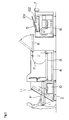
- Figs. 5 and 6 are schematic side views of the auto-loader unit 4.
- Fig. 5 schematically shows a state before a plate transporting operation
- Fig. 6 a state after the plate transporting operation.
- This auto-loader unit 4 includes a moving device 200 driven by an endless synchronous belt 61 rotatable by a motor 60, to run along a guide rail 62.
- the moving device 200 is engaged with the synchronous belt 61 through a mobile member 63.
- the moving device 200 has an arm 66 swingable relative thereto.
- the arm 66 has a plurality of suction pads 67 attached to a distal end thereof for sucking and holding a plate P.
- the arm 66 has a support roller 69 disposed at the distal end thereof for supporting the lower surface of a forward end region of the plate P when transporting the plate P.
- the arm 66 is connected to an arm 202 having a support roller 71 disposed at a distal end thereof for supporting the lower surface of a central region of the plate P.
- the arm 66 is driven by a motor 205 described hereinafter, to swing with the arm 202 about the moving device 200.
- the auto-loader unit 4 has a guard paper discharge mechanism for discharging slip sheet S inserted between the plates P.
- Fig. 7 is a schematic side view of the moving device 200 and adjacent elements.
- Fig. 8 is a perspective view showing a principal portion thereof.
- the mobile member 63 is omitted from Fig. 7.
- the arm 66 noted above is connected to a shaft 213 (Fig. 8) included in the moving device 200, to be swingable about this shaft 213.
- the shaft 213 is connected to a shaft 208 through spur gears 212, 211, 210 and 209.
- the shaft 208 is connected to a drive shaft of the motor 205 through spur gears 207 and 206.
- the arm 66 is driven by the motor 205 to swing about the shaft 213.
- Part of this arm 66 acts as a rack 216.
- the rack 216 is meshed with a spur gear 215 mounted on a shaft 214 rotatable by a motor not shown.
- the arm 66 has a length determined by a rotational position of the spur gear 215. Thus, the length of the arm 66 is adjustable according to the number of plates P stored in the cassette 9.
- the moving device 200 is driven by the motor 60 to move along the surfaces of the plates P stored in the cassette 9.
- the suction pads 67 arranged at the distal end of the arm 66 are swung about the shaft 213 included in the moving device 200.
- FIGs. 9 through 14B are schematic views showing an operation of the auto-loader unit 4 to feed a relatively small plate P.
- the mobile member 63 is omitted also from Figs. 9 through 14B.
- the plates P stored in the cassette 9 are omitted from Figs. 9 through 13.
- the moving device 200 When starting transportation of a plate P, as shown in Figs. 5 and 9, the moving device 200 is moved by the motor 60 to move the suction pads 67 adjacent the end of the plate P remote from the nip rollers 72 and 73, and cause the suction pads 67 to suck and hold the upper surface of the plate P. At this time, the plates P stored in the cassette 9 are in a state of having end edges adjacent the nip rollers 72 and 73 made even and positioned by a stopper 201.
- the moving device 200 is driven by the motor 60 to move toward the nip rollers 72 and 73.
- the arm 66 is driven by the motor 205 to swing clockwise about the shaft 213. Consequently, the plate P begins to be turned back as shown in Fig. 10.
- the moving device 200 is driven by the motor 60 to move away from the nip rollers 72 and 73.
- the support roller 71 disposed at the distal end of the arm 202 contacts a central region of the plate P.
- the moving device 200 is moved further away from the nip rollers 72 and 73. Consequently, as shown in Fig. 12, the support roller 71 presses the central region of the plate P to a position on the side of the stopper 201 remote from the nip rollers 72 and 73.
- the moving device 200 is moved leftward, with the angle of the arm 202 maintained, from the position shown in Fig. 11 (with the suction pads 67 lying near the nip rollers 72 and 73) to the position shown in Fig. 12.
- the support roller 71 pressing a central region on an inner peripheral surface of a curved portion of the plate P reaches a position on the left side of a vertical line L extending from the stopper 201 (that is, a position on the side of the stopper 201 remote from the nip rollers 72 and 73).
- the nip rollers 72 and 73 are rotated to transport the plate P.
- the plate P is guided by the support rollers 69 and 71.
- the curved portion of the plate P between the nip rollers 72 and 73 and the stopper 201 gradually becomes short, and its shape gradually changes from curve to straight.
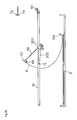
- the above change in shape can be stopped halfway when the plate P, with the central region thereof pressed, is fed by the nip rollers 72 and 73. It is therefore possible, as shown in Figs. 12 and 14A, to raise the uppermost plate P at a predetermined angle ⁇ 1 to the rest of the plates P stored.
- this auto-loader unit 4 is constructed such that, when a plate P is transported by the nip rollers 72 and 73, the support roller 71 presses the central region of the plate P to a position on the side of the stopper 201 remote from the nip rollers 72 and 73.
- both of the arm 202 with the support roller 71 acting as the pressing member and the arm 66 with the suction pads 67 are provided for the common moving device 200. It is therefore impossible for the pressing member to make horizontal movement independently of operation of the suction pads 67. The pressing member needs to start pressing the plate P after the suction pads 67 release the plate P.
- the pressing member and suction pads 67 can be moved horizontally and separately from each other, it is not necessary to start moving the pressing member horizontally after the nip rollers 72 and 73 pinch the forward end of the plate P. That is, it is possible to start moving the pressing member horizontally while the plate P is being turned back, before the forward end of the plate P is pinched by the nip rollers 72 and 73.
Landscapes
- Engineering & Computer Science (AREA)
- Mechanical Engineering (AREA)
- Sheets, Magazines, And Separation Thereof (AREA)
Abstract
Description
- This invention relates to a plate feeding apparatus for transporting stacked printing plates in order from an uppermost plate, and in an inverted state, to a plate takeout unit such as nip rollers.
-
Japanese Unexamined Patent Publication No. 2000-247489 - Such a plate feeding apparatus that transports printing plates, in an inverted state, to the plate takeout unit has an advantage of transporting the plates reliably without occupying a large floor space even when transporting relatively large plates.
- In such a plate feeding apparatus, plates are usually stacked with end edges aligned by a stopper. Then, with the plate feeding apparatus that transports the plates, in an inverted state, to the plate takeout unit, when a distance from a plate storage unit to the plate takeout unit is small for the size of the plates, the rear end of a plate will thrust itself in between the end edges of the plates stacked and the stopper, making it impossible to transport the plate properly.
- In order to solve this problem, it is conceivable to secure a sufficiently large distance from the plate storage unit to the plate takeout unit in accordance with the size of the plates. However, the increasingly large printing plates used nowadays will result in the entire apparatus occupying a large space.
- The object of this invention, therefore, is to provide a plate feeding apparatus and a plate feeding method which can transport plates reliably without enlarging the apparatus.
- The above object is fulfilled, according to this invention, by a plate feeding apparatus for transporting plates loaded therein, in order from an uppermost plate, while inverting the plates, toward a plate takeout unit that holds and takes out the plate, the apparatus comprising a storage unit for storing a plurality of plates with end edges aligned by a stopper; a moving unit movable along surfaces of the plates stored in the storage unit; a suction unit disposed at a distal end of an arm swingable about the moving unit for sucking and holding an upper surface adjacent an end edge, remote from the plate takeout unit, of each of the plates stored in the storage unit; a moving mechanism for moving the moving unit along the surfaces of the plates stored in the storage unit, from a position remote from the plate takeout unit toward the plate takeout unit, and for swinging the arm about the moving unit, thereby moving the suction unit to invert a portion adjacent the end edge of each plate sucked and held by the suction unit, and subsequently to reach a position for each plate to be held by the plate takeout unit; a pressing member for pressing an inner peripheral surface of a curved portion of each plate which has been curved while being inverted, to locate the curved portion further remote from the plate takeout unit than a vertical line extending from the stopper; and a pressing member moving device for moving the pressing member away from the plate takeout unit.
- Such plate feeding apparatus can transport plates reliably without enlarging the apparatus.
- In a preferred embodiment, the plate feeding apparatus includes a pressing member moving device. Thus, the pressing member can, in a selected position along the surfaces of the plates stored, press a portion of an inner peripheral surface of each plate curved as it is turned back. It is therefore possible to perform properly even when the position of the pressing member pressing plates is changed to handle plates of different sizes.
- In a further aspect of the invention, a plate feeding method is provided for transporting plates stored in a storage unit with end edges of the plates aligned by a stopper, in order from an uppermost plate, while inverting the plates, to nip rollers, the method comprising a suction-holding step for causing a suction unit to suck and hold an upper surface adjacent an end edge, remote from the nip rollers, of each of the plates stored in the storage unit; a moving step, while swinging the suction unit about a moving unit, for moving the moving unit along the surfaces of the plates stored in the storage unit, from a position remote from the nip rollers toward the nip rollers, thereby inverting a portion adjacent the end edge of each plate sucked and held by the suction unit, and subsequently moving the end edge of each plate to a position to be pinched by the nip rollers; a pinching step for causing the nip rollers to pinch the end edge of each plate having been inverted; a releasing step for canceling suction-holding of each plate by the suction unit; and a pressing step for pressing each plate with a pressing member from adjacent the nip rollers to a position further remote from the nip rollers than the stopper.
- Other features and advantages of the invention will be apparent from the following detailed description of the embodiments of the invention.
- For the purpose of illustrating the invention, there are shown in the drawings several forms which are presently preferred, it being understood, however, that the invention is not limited to the precise arrangement and instrumentalities shown.
- Fig. 1 is a perspective view of an image recording system having a plate feeding apparatus according to this invention;
- Fig. 2 is a schematic side view of the image recording system having the plate feeding apparatus according to this invention;
- Fig. 3 is a schematic plan view of the image recording system having the plate feeding apparatus according to this invention;
- Fig. 4 is a perspective view of a cassette tray swing mechanism;
- Fig. 5 is a schematic side view of an auto-loader unit;
- Fig. 6 is a schematic side view of the auto-loader unit;
- Fig. 7 is a schematic side view of a moving device and adjacent elements;
- Fig. 8 is a perspective view showing a principal portion of the moving device and adjacent elements;
- Fig. 9 is a schematic view showing the auto-loader unit in an operation to transport a printing plate;
- Fig. 10 is a schematic view showing the auto-loader unit in the operation to transport the printing plate;
- Fig. 11 is a schematic view showing the auto-loader unit in the operation to transport the printing plate;
- Fig. 12 is a schematic view showing the auto-loader unit in the operation to transport the printing plate;
- Fig. 13 is a schematic view showing the auto-loader unit in the operation to transport the printing plate;
- Fig. 14A is a schematic view showing the auto-loader unit in the operation to transport the printing plate; and
- Fig. 14B is a schematic view showing the auto-loader unit in the operation to transport the printing plate.
- An embodiment of this invention will be described hereinafter with reference to the drawings. Fig. 1 is a perspective view of an image recording system having a plate feeding apparatus according to this invention. Fig. 2 is a schematic side view and Fig. 3 a schematic plan view of the system.
- This image recording system includes a
plate feed unit 2 for use in depositing plates P in eachcassette 9 acting as a storage unit, amulti-cassette unit 3 having a plurality ofcassettes 9 stacked one over the other, an auto-loader unit 4 for fetching and transporting plates P from acassette 9 moved to a plate feed position, a plate loading and unloadingtray unit 5 having aplate loading tray 131 and aplate unloading tray 132, aconveyor 8, animage recorder 6 for recording images on the plates P, and atransport mechanism 7 for transporting the plates P having images recorded thereon in theimage recorder 6 to anauto developing device 10 disposed at a downstream stage. - The
above conveyor 8 is provided to transport the plates P from the auto-loader unit 4 to the plate loading and unloadingtray unit 5. In order to facilitate maintenance of the entire apparatus, theconveyor 8 is constructed pivotable upward about one end thereof as shown in two-dot chain lines in Fig. 2. - In this image recording system, the
multi-cassette unit 3 accommodates a plurality ofcassettes 9 stacked one over the other. When transporting plates P in acassette 9 to theimage recorder 6, a slide mechanism moves thecassette 9 from themulti-cassette unit 3 to the auto-loader unit 4. Then, a lift mechanism moves thiscassette 9 vertically to the plate feed position shown in Fig. 2. - When storing new plates P in a
cassette 9, thecassette 9 is moved from themulti-cassette unit 3 to the auto-loader unit 4. Then, thiscassette 9 is moved vertically to a cassette fetch position level in which it is aligned horizontally with a cassette holder 11 in a horizontal position shown in solid lines in Fig. 2. Subsequently,motors loader unit 4 along guide members, not shown, into the cassette holder 11 in thecassette feed unit 2. - As shown in Fig. 4, this cassette holder 11 is disposed in the
plate feed unit 2 to be pivotable about ashaft 12. Theshaft 12 has aspur gear 13 formed peripherally of and coaxially with theshaft 12. On the other hand, theplate feed unit 2 has amotor 15 with aworm gear 14. Theworm gear 14 is meshed with aworm wheel 17 coaxial with aspur gear 16 meshed with thespur gear 13. Consequently, the cassette holder 11 is constructed pivotable by themotor 15 between the horizontal position shown in solid lines in Fig. 2 and a tilted position shown in phantom lines in Fig. 2. - When moving a
cassette 9 between the auto-loader unit 4 and cassette holder 11, the cassette holder 11 is set to the horizontal position. The cassette holder 11 may be horizontal also when storing relatively small plates P in acassette 9 having moved into the cassette holder 11. However, when storing relatively large plates P in thecassette 9, the cassette holder 11 is set to the tilted position. Then the relatively large plates P can be stored in thecassette 9 easily without bending such plates P. - The auto-
loader unit 4 which fetches and transports plates P from inside theabove cassette 9 constitutes the plate feeding apparatus according to this invention. The construction of this auto-loader unit 4 will be described hereinafter. - Figs. 5 and 6 are schematic side views of the auto-
loader unit 4. Fig. 5 schematically shows a state before a plate transporting operation, and Fig. 6 a state after the plate transporting operation. - This auto-
loader unit 4 includes a movingdevice 200 driven by an endlesssynchronous belt 61 rotatable by amotor 60, to run along aguide rail 62. The movingdevice 200 is engaged with thesynchronous belt 61 through amobile member 63. The movingdevice 200 has anarm 66 swingable relative thereto. Thearm 66 has a plurality ofsuction pads 67 attached to a distal end thereof for sucking and holding a plate P. Thearm 66 has asupport roller 69 disposed at the distal end thereof for supporting the lower surface of a forward end region of the plate P when transporting the plate P. Further, thearm 66 is connected to anarm 202 having asupport roller 71 disposed at a distal end thereof for supporting the lower surface of a central region of the plate P. Thearm 66 is driven by amotor 205 described hereinafter, to swing with thearm 202 about the movingdevice 200. - In this auto-
loader unit 4, as the movingdevice 200 is driven by themotor 60 to move rightward from the position shown in Fig. 5, thearm 66 swings about the movingdevice 200. Thus, when the movingdevice 200 is driven by themotor 60 to move rightward, with thesuction pads 67 sucking and holding a plate P, the plate P held by thesuction pads 67 is first turned back to become inverted as shown in Fig. 6. Subsequently, the resulting forward end of the plate P is pinched between a pair of niprollers conveyor 8. - It should be noted that the auto-
loader unit 4 has a guard paper discharge mechanism for discharging slip sheet S inserted between the plates P. - Fig. 7 is a schematic side view of the moving
device 200 and adjacent elements. Fig. 8 is a perspective view showing a principal portion thereof. Themobile member 63 is omitted from Fig. 7. - The
arm 66 noted above is connected to a shaft 213 (Fig. 8) included in the movingdevice 200, to be swingable about this shaft 213. The shaft 213 is connected to ashaft 208 throughspur gears shaft 208 is connected to a drive shaft of themotor 205 throughspur gears arm 66 is driven by themotor 205 to swing about the shaft 213. - Part of this
arm 66 acts as arack 216. Therack 216 is meshed with aspur gear 215 mounted on ashaft 214 rotatable by a motor not shown. Thearm 66 has a length determined by a rotational position of thespur gear 215. Thus, the length of thearm 66 is adjustable according to the number of plates P stored in thecassette 9. - In this auto-
loader unit 4, as described above, the movingdevice 200 is driven by themotor 60 to move along the surfaces of the plates P stored in thecassette 9. In time of this movement, thesuction pads 67 arranged at the distal end of thearm 66 are swung about the shaft 213 included in the movingdevice 200. - Next, an operation of the auto-
loader unit 4 to transport a plate P will be described. Figs. 9 through 14B are schematic views showing an operation of the auto-loader unit 4 to feed a relatively small plate P. Themobile member 63 is omitted also from Figs. 9 through 14B. The plates P stored in thecassette 9 are omitted from Figs. 9 through 13. - When starting transportation of a plate P, as shown in Figs. 5 and 9, the moving
device 200 is moved by themotor 60 to move thesuction pads 67 adjacent the end of the plate P remote from the niprollers suction pads 67 to suck and hold the upper surface of the plate P. At this time, the plates P stored in thecassette 9 are in a state of having end edges adjacent the niprollers stopper 201. - In this state, the moving
device 200 is driven by themotor 60 to move toward the niprollers arm 66 is driven by themotor 205 to swing clockwise about the shaft 213. Consequently, the plate P begins to be turned back as shown in Fig. 10. - The movement of the moving
device 200 and the swing of thearm 66 are continued, causing the end edge of the plate P to be pinched between the niprollers suction pads 67 is canceled. - Next, the moving
device 200 is driven by themotor 60 to move away from the niprollers support roller 71 disposed at the distal end of thearm 202 contacts a central region of the plate P. In this state, the movingdevice 200 is moved further away from the niprollers support roller 71 presses the central region of the plate P to a position on the side of thestopper 201 remote from the niprollers - That is, the moving
device 200 is moved leftward, with the angle of thearm 202 maintained, from the position shown in Fig. 11 (with thesuction pads 67 lying near the niprollers 72 and 73) to the position shown in Fig. 12. As a result, thesupport roller 71 pressing a central region on an inner peripheral surface of a curved portion of the plate P reaches a position on the left side of a vertical line L extending from the stopper 201 (that is, a position on the side of thestopper 201 remote from the niprollers 72 and 73). - Then, the nip
rollers support rollers - The following is the reason for causing the
support roller 71 to press the central region of the plate P to the position on the side of thestopper 201 remote from the niprollers - As the nip
rollers rollers stopper 201 gradually becomes short, and its shape gradually changes from curve to straight. However, the above change in shape can be stopped halfway when the plate P, with the central region thereof pressed, is fed by thenip rollers - On the other hand, when the plate P, without being pressed, is transported by the
nip rollers stopper 201 will take a vertical position. There occurs a phenomenon, as shown in Fig. 14B, of the end of the plate P adjacent thestopper 201 thrusting itself in between the end edges of the stacked plates P and thestopper 201. Such a phenomenon causes a problem that the plate P cannot be transported properly. Such a phenomenon tends to occur where the distance from the stack of plates P to the niprollers - Therefore, this auto-
loader unit 4 is constructed such that, when a plate P is transported by thenip rollers support roller 71 presses the central region of the plate P to a position on the side of thestopper 201 remote from the niprollers - In the embodiment described above, both of the
arm 202 with thesupport roller 71 acting as the pressing member and thearm 66 with thesuction pads 67 are provided for the common movingdevice 200. It is therefore impossible for the pressing member to make horizontal movement independently of operation of thesuction pads 67. The pressing member needs to start pressing the plate P after thesuction pads 67 release the plate P. - However, where the pressing member and
suction pads 67 can be moved horizontally and separately from each other, it is not necessary to start moving the pressing member horizontally after the niprollers nip rollers
Claims (6)
- A plate feeding apparatus for transporting plates loaded therein, in order from an uppermost plate, while inverting the plates, toward a plate takeout unit that holds and takes out the plate, said apparatus comprising:a storage unit (9) for storing a plurality of plates (P) with end edges aligned by a stopper (201);a moving unit (200) movable along surfaces of the plates (P) stored in said storage unit (9) ;a suction unit (67) disposed at a distal end of an arm (66) swingable about said moving unit (200) for sucking and holding an upper surface adjacent an end edge, remote from said plate takeout unit, of each of the plates (P) stored in said storage unit (9);a moving mechanism for moving said moving unit (200) along the surfaces of the plates (P) stored in said storage unit (9), from a position remote from said plate takeout unit toward said plate takeout unit, and for swinging said arm (66) about said moving unit (200), thereby moving said suction unit (67) to invert a portion adjacent the end edge of each plate (P) sucked and held by said suction unit (67), and subsequently to reach a position for each plate (P) to be held by said plate takeout unit;a pressing member (71) for pressing an inner peripheral surface of a curved portion of each plate (P) which has been curved while being inverted, to locate said curved portion further remote from said plate takeout unit than a vertical line extending from said stopper (201); anda pressing member moving device for moving said pressing member (71) away from said plate takeout unit.
- A plate feeding apparatus as defined in claim 1, wherein said pressing member (71) is connected to said moving unit to be movable therewith.
- A plate feeding apparatus as defined in claim 1, wherein said plate takeout unit includes nip rollers (72, 73), said pressing member (71) pressing each plate (P) from adjacent said nip rollers (72, 73) to a position further remote from said nip rollers (72, 73) than said stopper (201), after the nip rollers (72, 73) pinch the portion adjacent the end edge of each plate (P) sucked and held by said suction unit (67).
- A plate feeding apparatus as defined in claim 3, wherein said pressing member (71) is connected to said moving unit (200) to be movable therewith.
- A plate feeding method for transporting plates stored in a storage unit with end edges of the plates aligned by a stopper, in order from an uppermost plate, while inverting the plates, to nip rollers, said method comprising:a suction-holding step for causing a suction unit to suck and hold an upper surface adjacent an end edge, remote from said nip rollers, of each of the plates stored in said storage unit;a moving step, while swinging said suction unit about a moving unit, for moving said moving unit along the surfaces of the plates stored in said storage unit, from a position remote from said nip rollers toward said nip rollers , thereby inverting a portion adjacent the end edge of each plate sucked and held by said suction unit , and subsequently moving the end edge of each plate to a position to be pinched by said nip rollers ;a pinching step for causing said nip rollers to pinch the end edge of each plate having been inverted;a releasing step for canceling suction-holding of each plate by said suction unit; anda pressing step for pressing each plate with a pressing member from adjacent said nip rollers to a position further remote from said nip rollers than said stopper.
- A plate feeding method as defined in claim 5, further comprising a transporting step for rotating said nip rollers to transport each plate after said releasing step.
Applications Claiming Priority (1)
| Application Number | Priority Date | Filing Date | Title |
|---|---|---|---|
| JP2006155591A JP4688163B2 (en) | 2006-06-05 | 2006-06-05 | Plate supply apparatus and plate supply method |
Publications (3)
| Publication Number | Publication Date |
|---|---|
| EP1864927A2 true EP1864927A2 (en) | 2007-12-12 |
| EP1864927A3 EP1864927A3 (en) | 2008-09-10 |
| EP1864927B1 EP1864927B1 (en) | 2012-10-24 |
Family
ID=38462521
Family Applications (1)
| Application Number | Title | Priority Date | Filing Date |
|---|---|---|---|
| EP07010709A Not-in-force EP1864927B1 (en) | 2006-06-05 | 2007-05-30 | Plate feeding apparatus and plate feeding method |
Country Status (3)
| Country | Link |
|---|---|
| US (1) | US7913621B2 (en) |
| EP (1) | EP1864927B1 (en) |
| JP (1) | JP4688163B2 (en) |
Cited By (1)
| Publication number | Priority date | Publication date | Assignee | Title |
|---|---|---|---|---|
| EP1975098A3 (en) * | 2007-03-30 | 2010-02-17 | Dainippon Screen Mfg. Co., Ltd. | Plate Feeding Apparatus |
Families Citing this family (3)
| Publication number | Priority date | Publication date | Assignee | Title |
|---|---|---|---|---|
| CH710725B1 (en) * | 2008-04-17 | 2016-08-15 | Soudronic Ag | Hubtischabstapler and Behälterzargenschweissvorrichtung with such. |
| DE102013102454A1 (en) * | 2013-03-12 | 2014-09-18 | Krones Aktiengesellschaft | Method and device for singling intermediate layers provided on a stack |
| CN106965971B (en) * | 2017-05-12 | 2023-04-11 | 温州海航机械有限公司 | Automatic feeding device for knife, fork and spoon |
Family Cites Families (11)
| Publication number | Priority date | Publication date | Assignee | Title |
|---|---|---|---|---|
| JPS5451004U (en) * | 1977-09-16 | 1979-04-09 | ||
| JP4105317B2 (en) * | 1999-02-01 | 2008-06-25 | 株式会社サトー | Tag printer |
| JP3604942B2 (en) * | 1999-02-26 | 2004-12-22 | 大日本スクリーン製造株式会社 | Plate supply device |
| JP3569157B2 (en) * | 1999-06-14 | 2004-09-22 | 大日本スクリーン製造株式会社 | Plate supply device |
| JP2002316736A (en) * | 2001-04-23 | 2002-10-31 | Fuji Photo Film Co Ltd | Printing plate sheet feeder |
| JP2004018180A (en) * | 2002-06-17 | 2004-01-22 | Dainippon Screen Mfg Co Ltd | Slip sheet taking out device |
| US6776097B2 (en) * | 2002-10-02 | 2004-08-17 | Dainippon Screen Mfg. Co., Ltd. | Plate supplying apparatus |
| JP3897256B2 (en) * | 2003-03-25 | 2007-03-22 | 富士フイルム株式会社 | Printing plate feeder |
| JP2005289522A (en) * | 2004-03-31 | 2005-10-20 | Dainippon Screen Mfg Co Ltd | Slip sheet discharge device |
| JP4236186B2 (en) * | 2004-04-28 | 2009-03-11 | 大日本スクリーン製造株式会社 | Image recording material supply apparatus and method |
| JP4757222B2 (en) * | 2007-03-30 | 2011-08-24 | 大日本スクリーン製造株式会社 | Plate supply device |
-
2006
- 2006-06-05 JP JP2006155591A patent/JP4688163B2/en not_active Expired - Fee Related
-
2007
- 2007-05-30 EP EP07010709A patent/EP1864927B1/en not_active Not-in-force
- 2007-06-04 US US11/806,714 patent/US7913621B2/en not_active Expired - Fee Related
Cited By (1)
| Publication number | Priority date | Publication date | Assignee | Title |
|---|---|---|---|---|
| EP1975098A3 (en) * | 2007-03-30 | 2010-02-17 | Dainippon Screen Mfg. Co., Ltd. | Plate Feeding Apparatus |
Also Published As
| Publication number | Publication date |
|---|---|
| US7913621B2 (en) | 2011-03-29 |
| US20070280815A1 (en) | 2007-12-06 |
| EP1864927A3 (en) | 2008-09-10 |
| EP1864927B1 (en) | 2012-10-24 |
| JP4688163B2 (en) | 2011-05-25 |
| JP2007320749A (en) | 2007-12-13 |
Similar Documents
| Publication | Publication Date | Title |
|---|---|---|
| JP3661783B2 (en) | Document feeder and document feed control method | |
| JP3897256B2 (en) | Printing plate feeder | |
| JP2003015312A (en) | Printing plate sorting transport apparatus | |
| US8047533B2 (en) | Automatic document feeder | |
| CN101998928A (en) | Stacking apparatus, and image forming apparatus with the stacking apparatus | |
| EP1864927B1 (en) | Plate feeding apparatus and plate feeding method | |
| JP2002316736A (en) | Printing plate sheet feeder | |
| US7152531B2 (en) | Interleaf removal apparatus, plate feed apparatus and image recording system | |
| EP1975098B1 (en) | Plate Feeding Apparatus | |
| JP2003012165A (en) | Slip sheet removing mechanism for printing plate sheet conveying device | |
| JP6098222B2 (en) | Image forming apparatus | |
| JP4316784B2 (en) | Image exposure device | |
| JP4583242B2 (en) | Booklet exporter for bookbinding machine | |
| JP2001151360A (en) | Sucking and conveying device for printed form | |
| JPH0683132A (en) | Intermediate tray device for image forming device | |
| JP4149617B2 (en) | Output stacking device | |
| JPH11255346A (en) | Paper feeder | |
| JP2003276878A (en) | Image-recording material sheet carrier | |
| JP5671941B2 (en) | Plate-like printed material supply method and apparatus | |
| JPH07104527A (en) | Image forming apparatus with double-sided device | |
| JP2001201866A (en) | Plate-making device | |
| JP5274144B2 (en) | Duplex printing device | |
| JP3638213B2 (en) | Paper feeder | |
| JP2912411B2 (en) | Passbook handling equipment | |
| JP2004284789A (en) | Sheet handling device |
Legal Events
| Date | Code | Title | Description |
|---|---|---|---|
| PUAI | Public reference made under article 153(3) epc to a published international application that has entered the european phase |
Free format text: ORIGINAL CODE: 0009012 |
|
| AK | Designated contracting states |
Kind code of ref document: A2 Designated state(s): AT BE BG CH CY CZ DE DK EE ES FI FR GB GR HU IE IS IT LI LT LU LV MC MT NL PL PT RO SE SI SK TR |
|
| AX | Request for extension of the european patent |
Extension state: AL BA HR MK YU |
|
| PUAL | Search report despatched |
Free format text: ORIGINAL CODE: 0009013 |
|
| AK | Designated contracting states |
Kind code of ref document: A3 Designated state(s): AT BE BG CH CY CZ DE DK EE ES FI FR GB GR HU IE IS IT LI LT LU LV MC MT NL PL PT RO SE SI SK TR |
|
| AX | Request for extension of the european patent |
Extension state: AL BA HR MK RS |
|
| 17P | Request for examination filed |
Effective date: 20081224 |
|
| AKX | Designation fees paid |
Designated state(s): AT BE BG CH CY CZ DE DK EE ES FI FR GB GR HU IE IS IT LI LT LU LV MC MT NL PL PT RO SE SI SK TR |
|
| 17Q | First examination report despatched |
Effective date: 20090422 |
|
| GRAP | Despatch of communication of intention to grant a patent |
Free format text: ORIGINAL CODE: EPIDOSNIGR1 |
|
| RIN1 | Information on inventor provided before grant (corrected) |
Inventor name: MIYOSHI, HIROSHI |
|
| GRAS | Grant fee paid |
Free format text: ORIGINAL CODE: EPIDOSNIGR3 |
|
| GRAP | Despatch of communication of intention to grant a patent |
Free format text: ORIGINAL CODE: EPIDOSNIGR1 |
|
| GRAA | (expected) grant |
Free format text: ORIGINAL CODE: 0009210 |
|
| AK | Designated contracting states |
Kind code of ref document: B1 Designated state(s): AT BE BG CH CY CZ DE DK EE ES FI FR GB GR HU IE IS IT LI LT LU LV MC MT NL PL PT RO SE SI SK TR |
|
| REG | Reference to a national code |
Ref country code: GB Ref legal event code: FG4D |
|
| REG | Reference to a national code |
Ref country code: CH Ref legal event code: EP |
|
| REG | Reference to a national code |
Ref country code: AT Ref legal event code: REF Ref document number: 580802 Country of ref document: AT Kind code of ref document: T Effective date: 20121115 |
|
| REG | Reference to a national code |
Ref country code: IE Ref legal event code: FG4D |
|
| REG | Reference to a national code |
Ref country code: DE Ref legal event code: R096 Ref document number: 602007026213 Country of ref document: DE Effective date: 20121220 |
|
| REG | Reference to a national code |
Ref country code: AT Ref legal event code: MK05 Ref document number: 580802 Country of ref document: AT Kind code of ref document: T Effective date: 20121024 |
|
| REG | Reference to a national code |
Ref country code: NL Ref legal event code: VDEP Effective date: 20121024 |
|
| PG25 | Lapsed in a contracting state [announced via postgrant information from national office to epo] |
Ref country code: FI Free format text: LAPSE BECAUSE OF FAILURE TO SUBMIT A TRANSLATION OF THE DESCRIPTION OR TO PAY THE FEE WITHIN THE PRESCRIBED TIME-LIMIT Effective date: 20121024 Ref country code: NL Free format text: LAPSE BECAUSE OF FAILURE TO SUBMIT A TRANSLATION OF THE DESCRIPTION OR TO PAY THE FEE WITHIN THE PRESCRIBED TIME-LIMIT Effective date: 20121024 Ref country code: IS Free format text: LAPSE BECAUSE OF FAILURE TO SUBMIT A TRANSLATION OF THE DESCRIPTION OR TO PAY THE FEE WITHIN THE PRESCRIBED TIME-LIMIT Effective date: 20130224 Ref country code: SE Free format text: LAPSE BECAUSE OF FAILURE TO SUBMIT A TRANSLATION OF THE DESCRIPTION OR TO PAY THE FEE WITHIN THE PRESCRIBED TIME-LIMIT Effective date: 20121024 |
|
| PG25 | Lapsed in a contracting state [announced via postgrant information from national office to epo] |
Ref country code: LV Free format text: LAPSE BECAUSE OF FAILURE TO SUBMIT A TRANSLATION OF THE DESCRIPTION OR TO PAY THE FEE WITHIN THE PRESCRIBED TIME-LIMIT Effective date: 20121024 Ref country code: GR Free format text: LAPSE BECAUSE OF FAILURE TO SUBMIT A TRANSLATION OF THE DESCRIPTION OR TO PAY THE FEE WITHIN THE PRESCRIBED TIME-LIMIT Effective date: 20130125 Ref country code: PL Free format text: LAPSE BECAUSE OF FAILURE TO SUBMIT A TRANSLATION OF THE DESCRIPTION OR TO PAY THE FEE WITHIN THE PRESCRIBED TIME-LIMIT Effective date: 20121024 Ref country code: PT Free format text: LAPSE BECAUSE OF FAILURE TO SUBMIT A TRANSLATION OF THE DESCRIPTION OR TO PAY THE FEE WITHIN THE PRESCRIBED TIME-LIMIT Effective date: 20130225 Ref country code: CY Free format text: LAPSE BECAUSE OF FAILURE TO SUBMIT A TRANSLATION OF THE DESCRIPTION OR TO PAY THE FEE WITHIN THE PRESCRIBED TIME-LIMIT Effective date: 20121024 Ref country code: BE Free format text: LAPSE BECAUSE OF FAILURE TO SUBMIT A TRANSLATION OF THE DESCRIPTION OR TO PAY THE FEE WITHIN THE PRESCRIBED TIME-LIMIT Effective date: 20121024 Ref country code: SI Free format text: LAPSE BECAUSE OF FAILURE TO SUBMIT A TRANSLATION OF THE DESCRIPTION OR TO PAY THE FEE WITHIN THE PRESCRIBED TIME-LIMIT Effective date: 20121024 |
|
| PG25 | Lapsed in a contracting state [announced via postgrant information from national office to epo] |
Ref country code: AT Free format text: LAPSE BECAUSE OF FAILURE TO SUBMIT A TRANSLATION OF THE DESCRIPTION OR TO PAY THE FEE WITHIN THE PRESCRIBED TIME-LIMIT Effective date: 20121024 |
|
| PG25 | Lapsed in a contracting state [announced via postgrant information from national office to epo] |
Ref country code: EE Free format text: LAPSE BECAUSE OF FAILURE TO SUBMIT A TRANSLATION OF THE DESCRIPTION OR TO PAY THE FEE WITHIN THE PRESCRIBED TIME-LIMIT Effective date: 20121024 Ref country code: BG Free format text: LAPSE BECAUSE OF FAILURE TO SUBMIT A TRANSLATION OF THE DESCRIPTION OR TO PAY THE FEE WITHIN THE PRESCRIBED TIME-LIMIT Effective date: 20130124 Ref country code: SK Free format text: LAPSE BECAUSE OF FAILURE TO SUBMIT A TRANSLATION OF THE DESCRIPTION OR TO PAY THE FEE WITHIN THE PRESCRIBED TIME-LIMIT Effective date: 20121024 Ref country code: CZ Free format text: LAPSE BECAUSE OF FAILURE TO SUBMIT A TRANSLATION OF THE DESCRIPTION OR TO PAY THE FEE WITHIN THE PRESCRIBED TIME-LIMIT Effective date: 20121024 Ref country code: DK Free format text: LAPSE BECAUSE OF FAILURE TO SUBMIT A TRANSLATION OF THE DESCRIPTION OR TO PAY THE FEE WITHIN THE PRESCRIBED TIME-LIMIT Effective date: 20121024 |
|
| PG25 | Lapsed in a contracting state [announced via postgrant information from national office to epo] |
Ref country code: IT Free format text: LAPSE BECAUSE OF FAILURE TO SUBMIT A TRANSLATION OF THE DESCRIPTION OR TO PAY THE FEE WITHIN THE PRESCRIBED TIME-LIMIT Effective date: 20121024 Ref country code: RO Free format text: LAPSE BECAUSE OF FAILURE TO SUBMIT A TRANSLATION OF THE DESCRIPTION OR TO PAY THE FEE WITHIN THE PRESCRIBED TIME-LIMIT Effective date: 20121024 |
|
| PLBE | No opposition filed within time limit |
Free format text: ORIGINAL CODE: 0009261 |
|
| STAA | Information on the status of an ep patent application or granted ep patent |
Free format text: STATUS: NO OPPOSITION FILED WITHIN TIME LIMIT |
|
| 26N | No opposition filed |
Effective date: 20130725 |
|
| PG25 | Lapsed in a contracting state [announced via postgrant information from national office to epo] |
Ref country code: ES Free format text: LAPSE BECAUSE OF FAILURE TO SUBMIT A TRANSLATION OF THE DESCRIPTION OR TO PAY THE FEE WITHIN THE PRESCRIBED TIME-LIMIT Effective date: 20130204 |
|
| REG | Reference to a national code |
Ref country code: DE Ref legal event code: R097 Ref document number: 602007026213 Country of ref document: DE Effective date: 20130725 |
|
| PG25 | Lapsed in a contracting state [announced via postgrant information from national office to epo] |
Ref country code: MC Free format text: LAPSE BECAUSE OF FAILURE TO SUBMIT A TRANSLATION OF THE DESCRIPTION OR TO PAY THE FEE WITHIN THE PRESCRIBED TIME-LIMIT Effective date: 20121024 |
|
| REG | Reference to a national code |
Ref country code: CH Ref legal event code: PL |
|
| PG25 | Lapsed in a contracting state [announced via postgrant information from national office to epo] |
Ref country code: CH Free format text: LAPSE BECAUSE OF NON-PAYMENT OF DUE FEES Effective date: 20130531 Ref country code: LI Free format text: LAPSE BECAUSE OF NON-PAYMENT OF DUE FEES Effective date: 20130531 |
|
| REG | Reference to a national code |
Ref country code: IE Ref legal event code: MM4A |
|
| PG25 | Lapsed in a contracting state [announced via postgrant information from national office to epo] |
Ref country code: IE Free format text: LAPSE BECAUSE OF NON-PAYMENT OF DUE FEES Effective date: 20130530 |
|
| PG25 | Lapsed in a contracting state [announced via postgrant information from national office to epo] |
Ref country code: LT Free format text: LAPSE BECAUSE OF FAILURE TO SUBMIT A TRANSLATION OF THE DESCRIPTION OR TO PAY THE FEE WITHIN THE PRESCRIBED TIME-LIMIT Effective date: 20121024 |
|
| REG | Reference to a national code |
Ref country code: DE Ref legal event code: R082 Ref document number: 602007026213 Country of ref document: DE Representative=s name: BOEHMERT & BOEHMERT ANWALTSPARTNERSCHAFT MBB -, DE |
|
| PG25 | Lapsed in a contracting state [announced via postgrant information from national office to epo] |
Ref country code: MT Free format text: LAPSE BECAUSE OF FAILURE TO SUBMIT A TRANSLATION OF THE DESCRIPTION OR TO PAY THE FEE WITHIN THE PRESCRIBED TIME-LIMIT Effective date: 20121024 |
|
| REG | Reference to a national code |
Ref country code: DE Ref legal event code: R082 Ref document number: 602007026213 Country of ref document: DE Representative=s name: BOEHMERT & BOEHMERT ANWALTSPARTNERSCHAFT MBB -, DE Effective date: 20150220 Ref country code: DE Ref legal event code: R081 Ref document number: 602007026213 Country of ref document: DE Owner name: SCREEN HOLDINGS CO., LTD., JP Free format text: FORMER OWNER: DAINIPPON SCREEN MFG. CO., LTD., KYOTO, JP Effective date: 20121024 Ref country code: DE Ref legal event code: R081 Ref document number: 602007026213 Country of ref document: DE Owner name: SCREEN HOLDINGS CO., LTD., JP Free format text: FORMER OWNER: DAINIPPON SCREEN MFG. CO., LTD., KYOTO, JP Effective date: 20150220 |
|
| REG | Reference to a national code |
Ref country code: FR Ref legal event code: CA Effective date: 20150331 Ref country code: FR Ref legal event code: CD Owner name: SCREEN HOLDINGS CO., LTD., JP Effective date: 20150331 |
|
| PG25 | Lapsed in a contracting state [announced via postgrant information from national office to epo] |
Ref country code: TR Free format text: LAPSE BECAUSE OF FAILURE TO SUBMIT A TRANSLATION OF THE DESCRIPTION OR TO PAY THE FEE WITHIN THE PRESCRIBED TIME-LIMIT Effective date: 20121024 |
|
| PG25 | Lapsed in a contracting state [announced via postgrant information from national office to epo] |
Ref country code: HU Free format text: LAPSE BECAUSE OF FAILURE TO SUBMIT A TRANSLATION OF THE DESCRIPTION OR TO PAY THE FEE WITHIN THE PRESCRIBED TIME-LIMIT; INVALID AB INITIO Effective date: 20070530 Ref country code: LU Free format text: LAPSE BECAUSE OF NON-PAYMENT OF DUE FEES Effective date: 20130530 |
|
| REG | Reference to a national code |
Ref country code: FR Ref legal event code: PLFP Year of fee payment: 10 |
|
| REG | Reference to a national code |
Ref country code: FR Ref legal event code: PLFP Year of fee payment: 11 |
|
| REG | Reference to a national code |
Ref country code: FR Ref legal event code: PLFP Year of fee payment: 12 |
|
| PGFP | Annual fee paid to national office [announced via postgrant information from national office to epo] |
Ref country code: FR Payment date: 20210412 Year of fee payment: 15 Ref country code: DE Payment date: 20210505 Year of fee payment: 15 |
|
| PGFP | Annual fee paid to national office [announced via postgrant information from national office to epo] |
Ref country code: GB Payment date: 20210505 Year of fee payment: 15 |
|
| REG | Reference to a national code |
Ref country code: DE Ref legal event code: R119 Ref document number: 602007026213 Country of ref document: DE |
|
| GBPC | Gb: european patent ceased through non-payment of renewal fee |
Effective date: 20220530 |
|
| PG25 | Lapsed in a contracting state [announced via postgrant information from national office to epo] |
Ref country code: FR Free format text: LAPSE BECAUSE OF NON-PAYMENT OF DUE FEES Effective date: 20220531 |
|
| PG25 | Lapsed in a contracting state [announced via postgrant information from national office to epo] |
Ref country code: GB Free format text: LAPSE BECAUSE OF NON-PAYMENT OF DUE FEES Effective date: 20220530 Ref country code: DE Free format text: LAPSE BECAUSE OF NON-PAYMENT OF DUE FEES Effective date: 20221201 |