EP1864818A1 - Inkjet recording apparatus - Google Patents
Inkjet recording apparatus Download PDFInfo
- Publication number
- EP1864818A1 EP1864818A1 EP07010708A EP07010708A EP1864818A1 EP 1864818 A1 EP1864818 A1 EP 1864818A1 EP 07010708 A EP07010708 A EP 07010708A EP 07010708 A EP07010708 A EP 07010708A EP 1864818 A1 EP1864818 A1 EP 1864818A1
- Authority
- EP
- European Patent Office
- Prior art keywords
- ink
- pressure
- unit
- inkjet recording
- testing
- Prior art date
- Legal status (The legal status is an assumption and is not a legal conclusion. Google has not performed a legal analysis and makes no representation as to the accuracy of the status listed.)
- Withdrawn
Links
Images



Classifications
-
- B—PERFORMING OPERATIONS; TRANSPORTING
- B41—PRINTING; LINING MACHINES; TYPEWRITERS; STAMPS
- B41J—TYPEWRITERS; SELECTIVE PRINTING MECHANISMS, i.e. MECHANISMS PRINTING OTHERWISE THAN FROM A FORME; CORRECTION OF TYPOGRAPHICAL ERRORS
- B41J2/00—Typewriters or selective printing mechanisms characterised by the printing or marking process for which they are designed
- B41J2/005—Typewriters or selective printing mechanisms characterised by the printing or marking process for which they are designed characterised by bringing liquid or particles selectively into contact with a printing material
- B41J2/01—Ink jet
- B41J2/17—Ink jet characterised by ink handling
- B41J2/19—Ink jet characterised by ink handling for removing air bubbles
-
- B—PERFORMING OPERATIONS; TRANSPORTING
- B41—PRINTING; LINING MACHINES; TYPEWRITERS; STAMPS
- B41J—TYPEWRITERS; SELECTIVE PRINTING MECHANISMS, i.e. MECHANISMS PRINTING OTHERWISE THAN FROM A FORME; CORRECTION OF TYPOGRAPHICAL ERRORS
- B41J2/00—Typewriters or selective printing mechanisms characterised by the printing or marking process for which they are designed
- B41J2/005—Typewriters or selective printing mechanisms characterised by the printing or marking process for which they are designed characterised by bringing liquid or particles selectively into contact with a printing material
- B41J2/01—Ink jet
- B41J2/135—Nozzles
- B41J2/165—Prevention or detection of nozzle clogging, e.g. cleaning, capping or moistening for nozzles
- B41J2/16585—Prevention or detection of nozzle clogging, e.g. cleaning, capping or moistening for nozzles for paper-width or non-reciprocating print heads
-
- B—PERFORMING OPERATIONS; TRANSPORTING
- B41—PRINTING; LINING MACHINES; TYPEWRITERS; STAMPS
- B41J—TYPEWRITERS; SELECTIVE PRINTING MECHANISMS, i.e. MECHANISMS PRINTING OTHERWISE THAN FROM A FORME; CORRECTION OF TYPOGRAPHICAL ERRORS
- B41J2/00—Typewriters or selective printing mechanisms characterised by the printing or marking process for which they are designed
- B41J2/005—Typewriters or selective printing mechanisms characterised by the printing or marking process for which they are designed characterised by bringing liquid or particles selectively into contact with a printing material
- B41J2/01—Ink jet
- B41J2/17—Ink jet characterised by ink handling
- B41J2/175—Ink supply systems ; Circuit parts therefor
-
- B—PERFORMING OPERATIONS; TRANSPORTING
- B41—PRINTING; LINING MACHINES; TYPEWRITERS; STAMPS
- B41J—TYPEWRITERS; SELECTIVE PRINTING MECHANISMS, i.e. MECHANISMS PRINTING OTHERWISE THAN FROM A FORME; CORRECTION OF TYPOGRAPHICAL ERRORS
- B41J2/00—Typewriters or selective printing mechanisms characterised by the printing or marking process for which they are designed
- B41J2/005—Typewriters or selective printing mechanisms characterised by the printing or marking process for which they are designed characterised by bringing liquid or particles selectively into contact with a printing material
- B41J2/01—Ink jet
- B41J2/17—Ink jet characterised by ink handling
- B41J2/175—Ink supply systems ; Circuit parts therefor
- B41J2/17503—Ink cartridges
- B41J2/17506—Refilling of the cartridge
-
- B—PERFORMING OPERATIONS; TRANSPORTING
- B41—PRINTING; LINING MACHINES; TYPEWRITERS; STAMPS
- B41J—TYPEWRITERS; SELECTIVE PRINTING MECHANISMS, i.e. MECHANISMS PRINTING OTHERWISE THAN FROM A FORME; CORRECTION OF TYPOGRAPHICAL ERRORS
- B41J2/00—Typewriters or selective printing mechanisms characterised by the printing or marking process for which they are designed
- B41J2/005—Typewriters or selective printing mechanisms characterised by the printing or marking process for which they are designed characterised by bringing liquid or particles selectively into contact with a printing material
- B41J2/01—Ink jet
- B41J2/17—Ink jet characterised by ink handling
- B41J2/195—Ink jet characterised by ink handling for monitoring ink quality
-
- H—ELECTRICITY
- H05—ELECTRIC TECHNIQUES NOT OTHERWISE PROVIDED FOR
- H05K—PRINTED CIRCUITS; CASINGS OR CONSTRUCTIONAL DETAILS OF ELECTRIC APPARATUS; MANUFACTURE OF ASSEMBLAGES OF ELECTRICAL COMPONENTS
- H05K3/00—Apparatus or processes for manufacturing printed circuits
- H05K3/10—Apparatus or processes for manufacturing printed circuits in which conductive material is applied to the insulating support in such a manner as to form the desired conductive pattern
- H05K3/12—Apparatus or processes for manufacturing printed circuits in which conductive material is applied to the insulating support in such a manner as to form the desired conductive pattern using thick film techniques, e.g. printing techniques to apply the conductive material or similar techniques for applying conductive paste or ink patterns
- H05K3/1241—Apparatus or processes for manufacturing printed circuits in which conductive material is applied to the insulating support in such a manner as to form the desired conductive pattern using thick film techniques, e.g. printing techniques to apply the conductive material or similar techniques for applying conductive paste or ink patterns by ink-jet printing or drawing by dispensing
Definitions
- the present invention relates to an inkjet recording apparatus, particularly to an inkjet recording apparatus that prevents failures of ink-ejection.
- a problem of an ink-ejection failure i.e. failing in normal ejection of ink droplets in an inkjet recoding apparatus, is generally known.
- an inkjet recording apparatus is used in production of electronic devices and ink-ejection failures occur, a great loss results because the ink-ejection failures are directly linked to production failures. If such ink-ejection failures can be foreseen and prevented, the loss can be avoided.
- JP '459 discloses a technique of preventing an ink-ejection failure by projecting the ink-ejection failure, which occurs due to an increase of ink viscosity and entraining of air bubbles into a cavity, from patterns of a pressure vibration by detecting, through a pressure plate, a pressure vibration of the ink within a pressure chamber (referred to as a "cavity" in JP '459) in which a pressure for ejecting ink is produced.
- cavitation which occurs being associated with descending of an ink pressure when a pressure vibration is generated to eject ink. This cavitation occurs under the condition where cores, i.e. the cause of the cavitation, exist within ink and when a pressure of ink remarkably descends.
- JP '459 involves a problem that such ink-ejection failures cannot be prevented due to the reasons described below.
- the amplitudes of a pressure vibration that is detected are small even if the cavitation cores exit, this pressure vibration is virtually the same as in the case of non-existence of the cores within the ink. Therefore, the presence of the cores cannot be detected.
- an amplitude of pressure vibration detected is large, an occurrence of cavitation cannot be projected before the ink is ejected, because the ink as the object to be detected has been discharged from nozzle.
- an inkjet recording apparatus comprising: an inkjet recording head including an nozzle from which ink is ejected, a pressure chamber fluidly communicated with the nozzle, an ink supplying unit that supplies ink to the pressure chamber, and actuators for varying capacity of the pressure chamber; an ink-testing unit including an ink-test chamber, a pressure-vibration generating unit for generating a pressure vibration in said ink-test chamber, a pressure-vibration detecting unit for detecting the pressure vibration; an ink inlet through which ink is intaken into said ink-test chamber and an ink outlet through which the ink within said ink-test chamber is discharged; and a connecting unit for fluidly connecting the ink supplying unit with the ink outlet.
- Ink referred in the present invention includes not only a coloring material that merely forms characters or images but also a liquid that is ejected onto a printing medium by an inkjet recording apparatus including, e.g., electrically conductive materials used for forming wiring patterns of an electric circuit.
- the printing material also referred in the present invention means not only recording materials such as a paper that merely retains information of characters, images, or the like on its surface but also materials including a substrate used for an electric circuit on which a liquid ejected by an inkjet recording apparatus is made to be deposited.
- inkjet recording apparatus is comprised of an inkjet unit 48 comprising multiple inkjet recording heads 2 each ejecting ink, conveying unit for conveying a printing medium 15, ink-testing units 3a and 3b for testing ink supplied to inkjet unit 48, an ink-discharging unit for discharging unwanted ink, nozzle cap 14 for collecting ink from nozzles of inkjet unit 48, a drive unit for moving inkjet unit 48 and nozzle cap 14, an ink supply system coupled to inkjet unit 48 and nozzle cap 14, and electrical circuits that control and drive these structural components.
- the conveying unit is comprised of a conveyer belt 16, a conveying roller 17, and a conveyance motor 56 that drives the conveying roller.
- the conveying unit is provided with a charger unit 65 in the vicinity of conveyer belt 16, and carries a printing medium 15 by sucking the medium onto conveyer belt 16 by means of an electrostatic force.
- inkjet unit 48 when inkjet recording apparatus 1 is in a state of printing, inkjet unit 48 is held in the vicinity of conveyer belt 16. In this state, nozzle cap 14 is positioned escaping to a position where it does not disturb the operations of printing.
- inkjet unit 48 is set apart from conveyer belt 16 by drive units 60 and 61, moving to a position where nozzle cap 14 covers nozzles 34 of inkjet unit 48. In this state, nozzle cap 14 can collect ink discharged from nozzles 34.
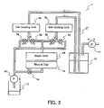
- the ink supply system is comprised of an ink tank 12 that stores ink, two ink-testing units 3a and 3b for testing ink, magnetic valves 5a, 5b, 5c, and 5d that each change a flow of the ink, a drainage pump 10 that discharges waste ink, a waste-ink storage tank 13 that stores discharged ink, and a pressure-adjusting pump 11 that adjusts a static pressure of the ink supplied to inkjet unit 48.
- the system is configured so that ink-testing units 3a and 3b are provided in parallel and the direction of the ink supply can be selected either toward the waste-ink discharging side or toward inkjet unit 48 by magnetic valves 5a, 5b, 5c, and 5d.
- the arrows in the FIGURE indicate directions of the ink or airflow.
- Magnetic valves 5a and 5b compose an ink-discharging unit in pairs.
- magnetic valves 5c and 5d compose another ink-discharging unit in pairs.
- Pressure-adjusting pump 11 adjusts an ink pressure within ink tank 12 based on a value of a static pressure detected by a pressure sensor 25 that is provided in inkjet unit 48.
- the static pressure of the ink supplied to inkjet unit 48 is adjusted to such a value that neither the ink runs out of the nozzles nor air is pulled into the nozzles from outside of inkjet unit 48.
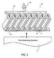
- Inkjet unit 48 is comprised of, as illustrated in FIG. 3, a plurality of inkjet recording heads 2, frame 63 that holds inkjet recording heads 2, ink-branching unit 62 that branches the ink supplied from outside of the inkjet unit to the individual inkjet recording heads 2, and a pressure sensor that detects a static pressure of the ink supplied to inkjet unit 48.
- Inkjet recording heads 2 are held by frame 63 at a predetermined angle relative to the printing scanning direction. Thus, high-resolution printing can be performed by a single operation of scanning.
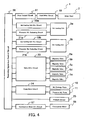
- the electric circuitry that controls inkjet recording apparatus 1 is comprised of a circuit for controlling the inkjet recording heads, a circuit for controlling the testing of the ink, a circuit for controlling the supply of the ink, a conveyance motor drive circuit 57 for driving conveyance motor 56 that conveys printing medium 15, and a recording apparatus control circuit 26 for integrally controlling these circuits.
- the inkjet recording head control circuit is comprised of a head drive circuit 18 that generates drive signals of inkjet recording heads 2 and a print control circuit 51 for controlling head drive circuit 18 according to print patterns.
- the control circuit for the ink-testing unit is comprised of ink-testing unit drive circuits 19a and 19b for driving a pressure-vibration generating unit 54 provided in ink-testing units 3a and 3b, and pressure-vibration evaluating circuits 21a and 21b that evaluates an electric signal generated by pressure-vibration detecting means 55 provided in ink-testing units 3 and judges a result of test of the ink.
- the ink-supply control circuit is comprised of a valve drive circuit 23 that individually opens and closes magnetic valves 5a, 5b, 5c, 5d, and 5e, and a pump drive circuit 24 that individually drives drainage pump 10 and pressure-adjusting pump 11.
- Inkjet recording head 2 is composed by a plurality of nozzles 34 that eject ink, a plurality of pressure chambers 35 that are communicated with the respective nozzles, a plurality of electrodes 39 formed on interior surfaces of the respective pressure chambers, a plurality of actuators 38a and 38b that are provided between pressure chambers 35, a common pressure chamber 31 that supplies ink being communicated with individual pressure chambers 35, and an ink supply port 30 from which ink is fed to common pressure chamber 31.
- Actuators 38a and 38b are each comprised of a lower piezoelectric member 36 and an upper piezoelectric member 37.
- Lower piezoelectric member 36 is polarized in its thickness direction, while upper piezoelectric member 37 is polarized in an opposite direction to that of lower piezoelectric member 36.
- Individual electrodes 39 are formed electrically independently and are separately connected to head drive circuit 18.
- Ink supply port 30 and common pressure chamber 31 compose an ink supplying unit that supplies ink to pressure chambers 35.
- inkjet recording head 2 continuously ejects the number of ink droplets corresponding to the number of the drive signals. As the ink droplets that are successively ejected are deposited on printing medium 15, the multiple droplets merge forming one dot having a size corresponding to the number of the ink droplets.
- so-called gradation control is enabled by controlling the number of the drive signals outputted by head drive circuit 18.
- ink is replenished in inkjet recording head 2 from ink tank 12 via ink-testing unit 3 by the ink-refilling effect that naturally occurs within nozzle 34.
- FIG. 7 is an elevational view of the ink-testing unit;
- FIG. 8 is a cross sectional view taken on line A-A in FIG. 7.
- Ink-testing unit 3 is comprised of a frame 49 having an ink-testing chamber 52 therein, a vibration plate 43a that is secured to one surface of frame 49, a vibration plate 43b that is secured to the other surface of frame 49, a piezoelectric member 45a that is secured to vibration plate 43a, a piezoelectric member 45b that is secured to vibration plate 43b, an ink inlet 41 and ink outlet 42 formed within vibration plate 43a.
- Tubes 27 are formed of a flexible material. This flexibility prevents the transmission of pressure vibration, which is generated within ink-testing chamber 52, to inkjet recording head 2 through tube 27.
- Frame 49 and vibration plates 43a and 43b are electrically conductive members. They are interconnected maintaining their conductivity and are grounded to the reference voltage of the electric circuit of inkjet recording apparatus 1.
- Piezoelectric members 45a and 45b are polarized in a Z direction.
- An electrode is formed on a surface opposite vibration plate 43a of piezoelectric member 45a.
- an electrode is also formed on a surface opposite vibration plate 43b of piezoelectric member 45b.
- the electrode formed on piezoelectric member 45a is electrically connected to ink-testing unit drive circuit 19; the electrode formed on piezoelectric member 45b is electrically connected to pressure-vibration evaluating circuit 21.
- Vibration plate 43a and piezoelectric member 45a compose a pressure-vibration generating unit 54 that imparts pressure vibration to the ink filled within the ink-testing chamber.
- Piezoelectric member 45a expands and contracts in Z-direction and Y-direction driven by a drive signal from ink-testing unit drive circuit 19.
- Vibration plate 43a is bent in a Z-direction associated with this expansion and contraction in a Y-direction. This bending action produces a pressure that impresses the ink within ink-testing chamber 52 so that a pressure vibration of the ink occurs.
- Vibration plate 43b and piezoelectric member 45b compose a pressure-vibration detecting unit 55 that detects the pressure vibration of the ink that is filled within ink-testing chamber 52.
- the pressure of the ink produced within ink-testing chamber 52 by the action of the expansion and contraction of piezoelectric member 45a effects to bend vibration plate 43b.
- This bending action expands and contracts piezoelectric member 45b in both Y-direction and X-direction.
- piezoelectric member 45b According to this expansion and contraction in Z-direction, piezoelectric member 45b generates a voltage vibration as shown in FIG. 9 according to the pressure vibration within ink-testing chamber 52.
- Pressure vibration evaluating circuit 21 tests the ink detecting the voltage vibration. This pressure-vibration evaluating circuit 21 tests if the amplitude of the voltage vibration is greater or smaller than a predetermined threshold value. The circuit judges that, if the amplitude is greater, the ink is normal ink that does not cause an ink-ejection failure by cavitation; it judges that, if smaller, the ink is abnormal ink that causes an ink-ejection failure.
- ink within ink-testing chamber 52 does not contain a cavitation core
- cavitation does not occur even if a negative pressure is produced within ink-testing chamber 52 in cooperation with the pressure vibration created by pressure-vibration generating unit 54. Because no cavitation occurs, the amplitude of pressure vibration within ink-testing chamber 52 is large. In this case, since the amplitude of pressure vibration created by pressure-vibration detecting unit 55 is greater than the threshold value, pressure-vibration evaluating circuit 21 judges the ink within ink-testing chamber 52 is to be normal ink.
- Each of the above ink-testing units is formed to separately comprise pressure-vibration generating unit 54 and pressure-vibration detecting unit 55.
- a structure that makes pressure-vibration generating unit 54 of ink-testing unit 3 serve also as pressure-vibration detecting unit 55 as shown in FIG. 10 may be formed.
- the structure may be constructed such that: a circuit selecting unit 58 is provided; ink-testing unit 3 is first connected to ink-testing unit drive circuit 19 so as to generate a pressure vibration within ink-testing chamber 52; subsequently, ink-testing unit 3 is switched to pressure-vibration evaluating circuit 21 to evaluate the amplitude of a residual pressure-vibration within ink-testing chamber 52.
- piezoelectric member 45 is employed for both pressure-vibration generating unit 54 and pressure vibration detecting unit 55.
- these generating unit and detecting unit can be composed using, for example, an electrostatic force.
- inkjet recording apparatus 1 Now, operations of inkjet recording apparatus 1 according to the present invention will be described. In this case, it will be assumed that ink-testing unit 3 and inkjet unit 48 are already filled with ink.
- inkjet recording apparatus 1 When inkjet recording apparatus 1 performs printing, inkjet unit 48 and nozzle cap 14 are situated in the printing state. Magnetic valves 5b and 5c are opened and magnetic valves 5a and 5d are closed.
- recording apparatus control circuit 26 transfers the data to print control circuit 51 and drives conveyer drive motor 53 so as to convey printing medium 15. Also, the recording apparatus control circuit drives pressure-vibration generating unit 54 of ink-testing unit 3.
- print control circuit 51 sends a control signal according to a gradient value of a print pattern to head drive circuit 18 and then head drive circuit 18 sends the number of drive signals according to the gradient value to inkjet recording head 2.
- inkjet recording head 2 receives the drive signals, performs printing by continuously ejecting ink droplets from nozzle 34 according to the number of the drive signals. In tandem with the operation of this ink-ejection, the ink corresponding to the amount of the ink that is ejected is replenished to nozzle 34 from ink tank 12 through ink-testing unit 3 by means of a natural refilling action.
- the ink When the ink is replenished to nozzles 34, the ink flows into ink-testing chamber 52 from ink inlet 41 of ink-testing unit 3, and the ink that has been tested is expelled from ink-testing chamber 52 to ink outlet 42.
- Pressure vibration detecting unit 55 tests the ink passing through ink-testing chamber 52 detecting pressure vibration generated by pressure-vibration generating unit 54, and judges whether the ink therein is abnormal ink having the cavitation cores or normal ink.
- ink abnormality is not detected in ink-testing unit 3a but is detected in ink-testing unit 3b
- magnetic valve 5d is made opened while magnetic valve 5c is made closed so that ink-testing unit 3b is connected to drainage pump 10.
- magnetic valve 5a remains closed and magnetic valve 5b remains opened.
- magnetic valve 5e is made closed and drainage pump 10 starts to operate.
- the abnormal ink that has been detected by ink-testing unit 3b is discharged into waste-ink storage tank 13 via magnetic valve 5d and drainage pump 10.
- ink-testing mean 3b continues performing of detecting abnormal ink.
- the drainage pump is made to stop, magnetic valve 5c is opened, and magnetic valve 5d is closed.
- inkjet recording apparatus 1 can discharge the abnormal ink without intermitting the performance of printing.
- the abnormal inks detected by ink-testing units 3a and 3b are discharged into waste-ink storage tank 13 without flowing into inkjet unit 48.
- inkjet recording apparatus 1 In the case that the abnormal ink is detected in both ink-testing units 3a and 3b, inkjet recording apparatus 1 must suspend the printing operation because of the disconnection of ink supply to inkjet unit 48.
- the possibility that the abnormal ink is detected simultaneously in the two ink-testing units 3a and 3b is extremely slim, the interruption of printing in inkjet recording apparatus 1 rarely occurs.
- two ink-testing units are implemented, the possibility of the printing interruption can be reduced by increasing the number of the ink-testing units.
- the drive signal of ink-testing unit drive circuit 19 is set so that the lower limit of the pressure vibration in ink-testing chamber 52 becomes lower than the lower limit of the pressure vibration, Pmim (FIG. 11), that is generated in pressure chambers 35 inkjet recording head 2. Since the possibility of occurrence of cavitation increases as the pressure becomes lower, the ink-ejection failure due to cavitation that occurs within pressure chambers 35 can be more assuredly prevented by lowering the lower limit of the pressure vibration that is created within ink-testing chamber 52 than the lower limit of the pressure vibration created within pressure chambers 35.
- the inkjet recording apparatus is provided with an ink-discharging unit discharging ink between inkjet recording head 2 that ejects ink and ink-testing units 3a and 3b that test the ink based on a result of ink test by ink-testing units 3a and 3b, the ink that is judged by ink-testing units 3a and 3b to be one that likely causes an ink-ejection failure can be discharged without going through inkjet recording head 2. Since inkjet recording head 2 is structured finely and delicately, it becomes difficult to totally remove ink from the recording head, once ink that potentially causes an ink-ejection failure is induced therein.
- the ink-ejection failure can be prevented from occurring by discharging the ink that potentially causes an ink-ejection failure before the ink enters inside inkjet recording head 2.
- the amount of the ink to be discharged can be reduced.
- an inkjet recording apparatus that does not waste ink can be provided.
- ink-testing units 3a and 3b in parallel with each ink-testing unit serially coupled with an ink-discharging unit, discharging of the ink that potentially causes an ink-ejection failure can be carried out without discontinuing an operation of printing by inkjet recording head 2.
- ink-testing unit 3 need not be limited to the structure, as used in this embodiment, that generates a pressure vibration.
- the same effect can be obtained by using a detecting unit employing other methods, e.g., a particle counter that optically detects particles or a dissolved oxygen meter.
- inkjet recording apparatus that is provided with a discharge ink storage tank that stores ink discharged by the ink-discharging unit.
- the ink discharged through the ink -discharging unit may be returned to the ink supply system after the ink is reproduced by the ink-reproducing unit, as shown in FIG. 12.
- a vacuum deaerator 66 is provided as the ink-reproducing unit, and the reproduced ink is returned to ink tank 12 via magnetic valve 5f.
- an ultrasonic generating device, filtering device using a filter, etc. may also be used.
- the amount of the ink that the ink-reproducing unit treats can be reduced by reproducing only ink that is discharged by ink-discharging unit 5. This yields such effects that the ink-reproducing unit can be downsized and energy consumed by the ink-reproducing unit can be saved.
Landscapes
- Engineering & Computer Science (AREA)
- Quality & Reliability (AREA)
- Ink Jet (AREA)
- Particle Formation And Scattering Control In Inkjet Printers (AREA)
Abstract
An inkjet recording apparatus comprises an inkjet recording head (2), an ink-testing unit (3a) having an ink-test chamber (52), a pressure-vibration generating unit (45a) that generates a pressure vibration in the ink-test chamber, a pressure-vibration detecting unit (45b) that detects the pressure vibration, an ink inlet (41) that introduces ink into the ink-test chamber (52) and an ink outlet (42) through which ink is discharged from the ink-test chamber (52). Failures of ink ejection can be prevented by detecting cavitation cores by the ink-test chamber and removing ink containing the cavitation cores from ink supplied to the inkjet recording head.
Description
- The present invention relates to an inkjet recording apparatus, particularly to an inkjet recording apparatus that prevents failures of ink-ejection.
- A problem of an ink-ejection failure, i.e. failing in normal ejection of ink droplets in an inkjet recoding apparatus, is generally known. When an inkjet recording apparatus is used in production of electronic devices and ink-ejection failures occur, a great loss results because the ink-ejection failures are directly linked to production failures. If such ink-ejection failures can be foreseen and prevented, the loss can be avoided.
- Relating to the above problem,
Japanese laid-open patent publication No. 2004-314459 - One of the causes of the ink-ejection failure is cavitation, which occurs being associated with descending of an ink pressure when a pressure vibration is generated to eject ink. This cavitation occurs under the condition where cores, i.e. the cause of the cavitation, exist within ink and when a pressure of ink remarkably descends.
- The art disclosed in JP '459 involves a problem that such ink-ejection failures cannot be prevented due to the reasons described below. In the case that the amplitudes of a pressure vibration that is detected are small even if the cavitation cores exit, this pressure vibration is virtually the same as in the case of non-existence of the cores within the ink. Therefore, the presence of the cores cannot be detected. Even in the case that an amplitude of pressure vibration detected is large, an occurrence of cavitation cannot be projected before the ink is ejected, because the ink as the object to be detected has been discharged from nozzle.
- To solve the above-described problem, there is provided an inkjet recording apparatus according to one embodiment of the present invention, comprising: an inkjet recording head including an nozzle from which ink is ejected, a pressure chamber fluidly communicated with the nozzle, an ink supplying unit that supplies ink to the pressure chamber, and actuators for varying capacity of the pressure chamber; an ink-testing unit including an ink-test chamber, a pressure-vibration generating unit for generating a pressure vibration in said ink-test chamber, a pressure-vibration detecting unit for detecting the pressure vibration; an ink inlet through which ink is intaken into said ink-test chamber and an ink outlet through which the ink within said ink-test chamber is discharged; and a connecting unit for fluidly connecting the ink supplying unit with the ink outlet.
- These and other objects and advantages of this invention will become apparent and more readily appreciated from the following detailed description of the presently preferred exemplary embodiments of the invention taken in conjunction with the accompanying drawings, wherein:
- FIG. 1 is a schematic diagram of an inkjet recording apparatus according to one embodiment of the present invention;
- FIG. 2 is a schematic diagram of an ink supply system according to the same embodiment of the present invention;
- FIG. 3 is a schematic diagram of an inkjet unit according to the same embodiment of the present invention;
- FIG. 4 is a block diagram of a drive circuit according to the same embodiment of the present invention;
- FIG. 5 is a vertical cross-sectional view of an inkjet recording head according to the same embodiment of the present invention;
- FIG. 6. is a traverse cross-sectional view of an inkjet recording head according to the same embodiment of the present invention;
- FIG. 7 is an external view of an ink-testing unit according to the same embodiment of the present invention;
- FIG. 8 is a cross-sectional view of the ink-testing unit according to the same embodiment of the present invention;
- FIG. 9 is a diagram showing pressure vibration occurred in an ink-testing unit and a related voltage vibration according to the same embodiment of the present invention;
- FIG. 10 is a modified example of an ink-testing unit according to the present invention;
- FIG. 11 is a diagram showing a pressure vibration occurred in a pressure chamber of the inkjet recording head according to the embodiment of the present invention;
- FIG. 12 is a modified example of the inkjet recording apparatus according to the present invention.
- The present invention will now be described in more detail with reference to the accompanying drawings. However, the same numerals are applied to the similar elements in the drawings, and therefore, the detailed descriptions thereof are not repeated.
- The preferred embodiment according to the present invention will now be described below. "Ink" referred in the present invention includes not only a coloring material that merely forms characters or images but also a liquid that is ejected onto a printing medium by an inkjet recording apparatus including, e.g., electrically conductive materials used for forming wiring patterns of an electric circuit. The printing material also referred in the present invention means not only recording materials such as a paper that merely retains information of characters, images, or the like on its surface but also materials including a substrate used for an electric circuit on which a liquid ejected by an inkjet recording apparatus is made to be deposited.
- Now, a structure of an inkjet recording apparatus according to the present invention will be described.
- As illustrated in FIGS. 1- 3, inkjet recording apparatus is comprised of an
inkjet unit 48 comprising multipleinkjet recording heads 2 each ejecting ink, conveying unit for conveying aprinting medium 15, ink-testing units inkjet unit 48, an ink-discharging unit for discharging unwanted ink,nozzle cap 14 for collecting ink from nozzles ofinkjet unit 48, a drive unit for movinginkjet unit 48 andnozzle cap 14, an ink supply system coupled toinkjet unit 48 andnozzle cap 14, and electrical circuits that control and drive these structural components. - Referring to FIG. 1, the conveying unit is comprised of a
conveyer belt 16, aconveying roller 17, and aconveyance motor 56 that drives the conveying roller. The conveying unit is provided with acharger unit 65 in the vicinity ofconveyer belt 16, and carries aprinting medium 15 by sucking the medium ontoconveyer belt 16 by means of an electrostatic force. - Referring to FIG. 1(a), when
inkjet recording apparatus 1 is in a state of printing,inkjet unit 48 is held in the vicinity ofconveyer belt 16. In this state,nozzle cap 14 is positioned escaping to a position where it does not disturb the operations of printing. - Referring to FIG. 1(b), in a maintenance state of
inkjet recording apparatus 1,inkjet unit 48 is set apart fromconveyer belt 16 bydrive units nozzle cap 14 coversnozzles 34 ofinkjet unit 48. In this state,nozzle cap 14 can collect ink discharged fromnozzles 34. - Referring to FIG. 2, the ink supply system is comprised of an
ink tank 12 that stores ink, two ink-testing units magnetic valves drainage pump 10 that discharges waste ink, a waste-ink storage tank 13 that stores discharged ink, and a pressure-adjustingpump 11 that adjusts a static pressure of the ink supplied toinkjet unit 48. The system is configured so that ink-testing units inkjet unit 48 bymagnetic valves -
Magnetic valves magnetic valves - Pressure-adjusting
pump 11 adjusts an ink pressure withinink tank 12 based on a value of a static pressure detected by apressure sensor 25 that is provided ininkjet unit 48. The static pressure of the ink supplied toinkjet unit 48 is adjusted to such a value that neither the ink runs out of the nozzles nor air is pulled into the nozzles from outside ofinkjet unit 48. -
Inkjet unit 48 is comprised of, as illustrated in FIG. 3, a plurality ofinkjet recording heads 2,frame 63 that holdsinkjet recording heads 2, ink-branching unit 62 that branches the ink supplied from outside of the inkjet unit to the individualinkjet recording heads 2, and a pressure sensor that detects a static pressure of the ink supplied toinkjet unit 48. -
Inkjet recording heads 2 are held byframe 63 at a predetermined angle relative to the printing scanning direction. Thus, high-resolution printing can be performed by a single operation of scanning. - Referring to FIG. 4, the electric circuitry that controls
inkjet recording apparatus 1 is comprised of a circuit for controlling the inkjet recording heads, a circuit for controlling the testing of the ink, a circuit for controlling the supply of the ink, a conveyancemotor drive circuit 57 for drivingconveyance motor 56 that conveysprinting medium 15, and a recordingapparatus control circuit 26 for integrally controlling these circuits. The inkjet recording head control circuit is comprised of ahead drive circuit 18 that generates drive signals ofinkjet recording heads 2 and aprint control circuit 51 for controllinghead drive circuit 18 according to print patterns. The control circuit for the ink-testing unit is comprised of ink-testingunit drive circuits unit 54 provided in ink-testing units vibration evaluating circuits testing units 3 and judges a result of test of the ink. The ink-supply control circuit is comprised of avalve drive circuit 23 that individually opens and closesmagnetic valves pump drive circuit 24 that individually drivesdrainage pump 10 and pressure-adjustingpump 11. -
Inkjet recording head 2, as illustrated in FIGS. 5 and 6, is composed by a plurality ofnozzles 34 that eject ink, a plurality ofpressure chambers 35 that are communicated with the respective nozzles, a plurality ofelectrodes 39 formed on interior surfaces of the respective pressure chambers, a plurality ofactuators pressure chambers 35, acommon pressure chamber 31 that supplies ink being communicated withindividual pressure chambers 35, and anink supply port 30 from which ink is fed tocommon pressure chamber 31.Actuators piezoelectric member 36 and an upperpiezoelectric member 37. Lowerpiezoelectric member 36 is polarized in its thickness direction, while upperpiezoelectric member 37 is polarized in an opposite direction to that of lowerpiezoelectric member 36.Individual electrodes 39 are formed electrically independently and are separately connected tohead drive circuit 18.Ink supply port 30 andcommon pressure chamber 31 compose an ink supplying unit that supplies ink topressure chambers 35. - When a drive signal from
head drive circuit 18 is applied to, for example,electrode 39b in a state that ink is filled withinpressure chamber 35 andnozzle 34, the actuators deforms in the shear mode by the effect of the electric field and the capacity of thepressure chamber 35 varies. Thereby ink filled withinpressure chambers 35 is pressurized and a pressure vibration occurs within pressure chamber. By this pressure vibration an ink droplet is ejected fromnozzle 34. - When multiple drive signals are continuously applied to the electrode from
head drive circuit 18,inkjet recording head 2 continuously ejects the number of ink droplets corresponding to the number of the drive signals. As the ink droplets that are successively ejected are deposited onprinting medium 15, the multiple droplets merge forming one dot having a size corresponding to the number of the ink droplets. Thus, so-called gradation control is enabled by controlling the number of the drive signals outputted byhead drive circuit 18. - As the ink droplet is ejected, ink is replenished in
inkjet recording head 2 fromink tank 12 via ink-testing unit 3 by the ink-refilling effect that naturally occurs withinnozzle 34. - The structure of ink-
testing unit 3 will be described in reference to FIGS. 7 and 8. FIG. 7 is an elevational view of the ink-testing unit; FIG. 8 is a cross sectional view taken on line A-A in FIG. 7. Ink-testing unit 3 is comprised of aframe 49 having an ink-testing chamber 52 therein, avibration plate 43a that is secured to one surface offrame 49, avibration plate 43b that is secured to the other surface offrame 49, apiezoelectric member 45a that is secured tovibration plate 43a, apiezoelectric member 45b that is secured tovibration plate 43b, anink inlet 41 andink outlet 42 formed withinvibration plate 43a. -
Ink inlet 41 andink outlet 42 are respectively connected totubes 27.Tubes 27 are formed of a flexible material. This flexibility prevents the transmission of pressure vibration, which is generated within ink-testing chamber 52, toinkjet recording head 2 throughtube 27. -
Frame 49 andvibration plates inkjet recording apparatus 1. - Piezoelectric
members vibration plate 43a ofpiezoelectric member 45a. Similarly, an electrode is also formed on a surface oppositevibration plate 43b ofpiezoelectric member 45b. The electrode formed onpiezoelectric member 45a is electrically connected to ink-testingunit drive circuit 19; the electrode formed onpiezoelectric member 45b is electrically connected to pressure-vibration evaluating circuit 21. -
Vibration plate 43a andpiezoelectric member 45a compose a pressure-vibration generating unit 54 that imparts pressure vibration to the ink filled within the ink-testing chamber.Piezoelectric member 45a expands and contracts in Z-direction and Y-direction driven by a drive signal from ink-testingunit drive circuit 19.Vibration plate 43a is bent in a Z-direction associated with this expansion and contraction in a Y-direction. This bending action produces a pressure that impresses the ink within ink-testing chamber 52 so that a pressure vibration of the ink occurs. -
Vibration plate 43b andpiezoelectric member 45b compose a pressure-vibration detecting unit 55 that detects the pressure vibration of the ink that is filled within ink-testing chamber 52. The pressure of the ink produced within ink-testing chamber 52 by the action of the expansion and contraction ofpiezoelectric member 45a effects to bendvibration plate 43b. This bending action expands and contractspiezoelectric member 45b in both Y-direction and X-direction. According to this expansion and contraction in Z-direction,piezoelectric member 45b generates a voltage vibration as shown in FIG. 9 according to the pressure vibration within ink-testing chamber 52. - Pressure
vibration evaluating circuit 21 tests the ink detecting the voltage vibration. This pressure-vibration evaluating circuit 21 tests if the amplitude of the voltage vibration is greater or smaller than a predetermined threshold value. The circuit judges that, if the amplitude is greater, the ink is normal ink that does not cause an ink-ejection failure by cavitation; it judges that, if smaller, the ink is abnormal ink that causes an ink-ejection failure. - For example, where the ink within ink-
testing chamber 52 does not contain a cavitation core, cavitation does not occur even if a negative pressure is produced within ink-testing chamber 52 in cooperation with the pressure vibration created by pressure-vibration generating unit 54. Because no cavitation occurs, the amplitude of pressure vibration within ink-testing chamber 52 is large. In this case, since the amplitude of pressure vibration created by pressure-vibration detecting unit 55 is greater than the threshold value, pressure-vibration evaluating circuit 21 judges the ink within ink-testing chamber 52 is to be normal ink. - On the other hand, in the case that the ink within ink-
testing chamber 52 contains some cavitation cores, cavitation occurs within ink-testing chamber 52 due to a negative pressure by the pressure vibration created by pressure-vibration generating unit 54. When the cavitation occurs, air bubbles produced by the cavitation absorb the pressure vibration within ink-testing chamber 52 and thus the amplitude of the pressure vibration is diminished. Accordingly, the amplitude of the voltage vibration generated by pressure-vibration detecting unit 55 becomes smaller than the threshold value, pressure-vibration evaluating circuit 21judjes that the ink within ink-testing chamber 52 is to be abnormal ink. - Each of the above ink-testing units is formed to separately comprise pressure-
vibration generating unit 54 and pressure-vibration detecting unit 55. In lieu of this structure, a structure that makes pressure-vibration generating unit 54 of ink-testing unit 3 serve also as pressure-vibration detecting unit 55 as shown in FIG. 10 may be formed. In this case, the structure may be constructed such that: acircuit selecting unit 58 is provided; ink-testing unit 3 is first connected to ink-testingunit drive circuit 19 so as to generate a pressure vibration within ink-testing chamber 52; subsequently, ink-testing unit 3 is switched to pressure-vibration evaluating circuit 21 to evaluate the amplitude of a residual pressure-vibration within ink-testing chamber 52. - In this embodiment,
piezoelectric member 45 is employed for both pressure-vibration generating unit 54 and pressurevibration detecting unit 55. However, these generating unit and detecting unit can be composed using, for example, an electrostatic force. - Now, operations of
inkjet recording apparatus 1 according to the present invention will be described. In this case, it will be assumed that ink-testing unit 3 andinkjet unit 48 are already filled with ink. - When
inkjet recording apparatus 1 performs printing,inkjet unit 48 andnozzle cap 14 are situated in the printing state.Magnetic valves magnetic valves - When data of a print pattern is sent to recording
apparatus control circuit 26, recordingapparatus control circuit 26 transfers the data to printcontrol circuit 51 and drives conveyer drive motor 53 so as to conveyprinting medium 15. Also, the recording apparatus control circuit drives pressure-vibration generating unit 54 of ink-testing unit 3. - When printing medium 15 passes under
inkjet unit 48,print control circuit 51 sends a control signal according to a gradient value of a print pattern to headdrive circuit 18 and then headdrive circuit 18 sends the number of drive signals according to the gradient value toinkjet recording head 2. - Receiving the drive signals,
inkjet recording head 2 performs printing by continuously ejecting ink droplets fromnozzle 34 according to the number of the drive signals. In tandem with the operation of this ink-ejection, the ink corresponding to the amount of the ink that is ejected is replenished tonozzle 34 fromink tank 12 through ink-testing unit 3 by means of a natural refilling action. - When the ink is replenished to
nozzles 34, the ink flows into ink-testing chamber 52 fromink inlet 41 of ink-testing unit 3, and the ink that has been tested is expelled from ink-testing chamber 52 toink outlet 42. - Pressure
vibration detecting unit 55 tests the ink passing through ink-testing chamber 52 detecting pressure vibration generated by pressure-vibration generating unit 54, and judges whether the ink therein is abnormal ink having the cavitation cores or normal ink. - For example, in the case that ink abnormality is not detected in ink-
testing unit 3a but is detected in ink-testing unit 3b,magnetic valve 5d is made opened whilemagnetic valve 5c is made closed so that ink-testing unit 3b is connected todrainage pump 10. Meantime, since abnormality of the ink was not detected in ink-testing unit 3a,magnetic valve 5a remains closed andmagnetic valve 5b remains opened. Furthermore, whilemagnetic valve 5e is made closed and drainage pump 10 starts to operate. Thereby the abnormal ink that has been detected by ink-testing unit 3b is discharged into waste-ink storage tank 13 viamagnetic valve 5d anddrainage pump 10. Even during this operation of ink discharging, ink-testing mean 3b continues performing of detecting abnormal ink. When abnormal ink becomes undetected, the drainage pump is made to stop,magnetic valve 5c is opened, andmagnetic valve 5d is closed. - The abnormal ink detected by ink-testing mean 3b in a series of such operations is discharged into waste-
ink storage tank 13 without flowing intoinkjet unit 48. In the meantime, the ink that is judged to be normal by ink-testing unit 3a is continuously supplied toinkjet unit 48 viamagnetic valve 5b. In this wayinkjet recording apparatus 1 can discharge the abnormal ink without intermitting the performance of printing. - In the case, for example, that the abnormal ink is detected by both ink-
testing units magnetic valves magnetic valves magnetic valve 5e is made closed and drainage pump 10 starts to operate. As a result, the abnormal inks detected by ink-testing units ink storage tank 13 viamagnetic valves drainage pump 10. Even during this operation of ink discharging, ink-testing units magnetic valves magnetic valves - By the series of these operations, the abnormal inks detected by ink-
testing units ink storage tank 13 without flowing intoinkjet unit 48. In the case that the abnormal ink is detected in both ink-testing units inkjet recording apparatus 1 must suspend the printing operation because of the disconnection of ink supply toinkjet unit 48. However, since the possibility that the abnormal ink is detected simultaneously in the two ink-testing units inkjet recording apparatus 1 rarely occurs. Although in this embodiment two ink-testing units are implemented, the possibility of the printing interruption can be reduced by increasing the number of the ink-testing units. - To judge abnormality of the ink, as shown in FIG. 9, the drive signal of ink-testing
unit drive circuit 19 is set so that the lower limit of the pressure vibration in ink-testing chamber 52 becomes lower than the lower limit of the pressure vibration, Pmim (FIG. 11), that is generated inpressure chambers 35inkjet recording head 2. Since the possibility of occurrence of cavitation increases as the pressure becomes lower, the ink-ejection failure due to cavitation that occurs withinpressure chambers 35 can be more assuredly prevented by lowering the lower limit of the pressure vibration that is created within ink-testing chamber 52 than the lower limit of the pressure vibration created withinpressure chambers 35. - Firstly, in the inkjet recording apparatus according to the present invention, because
pressure chambers 35 where a pressure vibration for ejecting ink is generated is separated from ink-testing chamber 52 where a pressure vibration for testing the ink is generated, the pressure vibration for the ink testing cannot eject ink fromnozzles 34. Accordingly, the amplitude of the pressure vibration that is generated to test the ink can be provided at a larger value. Thus, ink that causes cavitation that does not likely occur unless the pressure becomes sufficiently low can be detected before the operation of ink-ejection, and thereby ink-ejection failure due to cavitation can be prevented from occurring. - Furthermore, by setting the lower limit of the pressure vibration generated for testing ink lower than the lower limit of the pressure vibration generated for ejecting ink, an ink-ejection failure can be more assuredly prevented from occurring.
- Secondly, because the inkjet recording apparatus according to the present invention is provided with an ink-discharging unit discharging ink between
inkjet recording head 2 that ejects ink and ink-testing units testing units testing units inkjet recording head 2. Sinceinkjet recording head 2 is structured finely and delicately, it becomes difficult to totally remove ink from the recording head, once ink that potentially causes an ink-ejection failure is induced therein. The ink-ejection failure can be prevented from occurring by discharging the ink that potentially causes an ink-ejection failure before the ink enters insideinkjet recording head 2. In addition, since there is no need to remove ink withininkjet recording head 2, the amount of the ink to be discharged can be reduced. Thus, an inkjet recording apparatus that does not waste ink can be provided. - Moreover, by providing ink-
testing units inkjet recording head 2. - Relating to the second effect in the above of the present invention, ink-
testing unit 3 need not be limited to the structure, as used in this embodiment, that generates a pressure vibration. The same effect can be obtained by using a detecting unit employing other methods, e.g., a particle counter that optically detects particles or a dissolved oxygen meter. - In the above embodiment, description has been made for inkjet recording apparatus that is provided with a discharge ink storage tank that stores ink discharged by the ink-discharging unit. Alternatively, the ink discharged through the ink -discharging unit may be returned to the ink supply system after the ink is reproduced by the ink-reproducing unit, as shown in FIG. 12. In this structure, a
vacuum deaerator 66 is provided as the ink-reproducing unit, and the reproduced ink is returned toink tank 12 viamagnetic valve 5f. As the ink-reproducing unit, an ultrasonic generating device, filtering device using a filter, etc. may also be used. The amount of the ink that the ink-reproducing unit treats can be reduced by reproducing only ink that is discharged by ink-discharging unit 5. This yields such effects that the ink-reproducing unit can be downsized and energy consumed by the ink-reproducing unit can be saved. - It is explicitly stated that all features disclosed in the description and/or the claims are intended to be disclosed separately and independently from each other for the purpose of original disclosure as well as for the purpose of restricting the claimed invention independent of the composition of the features in the embodiments and/or the claims. It is explicitly stated that all value ranges or indications of groups of entities disclose every possible intermediate value or intermediate entity for the purpose of original disclosure as well as for the purpose of restricting the claimed invention, in particular as limits of value ranges.
Claims (5)
- An inkjet recording apparatus having an inkjet recording head including a nozzle from which ink is ejected, a pressure chamber fluidly communicated with the nozzle, an ink supply unit that supplies ink to the pressure chamber, and actuators that vary a capacity of the pressure chamber, characterized by comprising:an ink-testing unit including an ink-test chamber, a pressure-vibration generating unit for generating a pressure vibration in the ink-test chamber, a pressure-vibration detecting unit for detecting an ink pressure-vibration in the ink-testing chamber, an ink inlet introducing ink into the ink-test chamber, and an ink outlet through which ink is discharged from the ink-test chamber; anda path for fluidly connecting the ink supply unit and the ink outlet.
- The inkjet recording apparatus according to claim 1, wherein a lower limit of a pressure of a pressure vibration generated within the ink-test chamber is set to be lower than a lower limit of a pressure of a pressure vibration generated within the pressure chamber.
- The inkjet recording apparatus according to claim 1, further comprising an ink-discharging unit that discharges the ink based on a result of test made by the ink-testing unit, the ink-discharging unit being fluidly connected between the ink-testing unit and the inkjet recording head.
- The inkjet recording apparatus according to claim 3, wherein a plurality of ink-testing units and a plurality of ink-discharging units are provided and the plurality of ink-testing units are disposed in parallel, each of the ink-testing units being coupled with one of the ink-discharging units.
- The inkjet recording apparatus according to claim 3, further comprising an ink-reproducing unit for reproducing ink that is discharged through the ink-discharging unit, wherein the ink reproduced by the reproduction unit is supplied to the inkjet recording head.
Applications Claiming Priority (1)
| Application Number | Priority Date | Filing Date | Title |
|---|---|---|---|
| JP2006158434A JP4539992B2 (en) | 2006-06-07 | 2006-06-07 | Inkjet recording device |
Publications (1)
| Publication Number | Publication Date |
|---|---|
| EP1864818A1 true EP1864818A1 (en) | 2007-12-12 |
Family
ID=38476933
Family Applications (1)
| Application Number | Title | Priority Date | Filing Date |
|---|---|---|---|
| EP07010708A Withdrawn EP1864818A1 (en) | 2006-06-07 | 2007-05-30 | Inkjet recording apparatus |
Country Status (4)
| Country | Link |
|---|---|
| US (2) | US7681997B2 (en) |
| EP (1) | EP1864818A1 (en) |
| JP (1) | JP4539992B2 (en) |
| CN (1) | CN100567004C (en) |
Families Citing this family (15)
| Publication number | Priority date | Publication date | Assignee | Title |
|---|---|---|---|---|
| JP5253258B2 (en) * | 2009-03-25 | 2013-07-31 | 富士フイルム株式会社 | Liquid ejection device |
| CN102145586B (en) * | 2010-02-05 | 2014-01-15 | 精工爱普生株式会社 | Fluid ejecting apparatus and cleaning method |
| JP2013000958A (en) * | 2011-06-15 | 2013-01-07 | Seiko Epson Corp | Liquid ejection device, inspection method, and program |
| JP5776447B2 (en) | 2011-08-30 | 2015-09-09 | セイコーエプソン株式会社 | Control device and excision device used in connection with fluid ejection device for excising biological tissue by ejected fluid |
| US9243619B2 (en) * | 2011-09-13 | 2016-01-26 | Seiko Epson Corporation | Liquid feed pump and circulation pump with detection units to detect operating states of the pumps |
| JP5328965B2 (en) * | 2011-10-20 | 2013-10-30 | キヤノン株式会社 | Recording apparatus and method for estimating discharge state thereof |
| JP5661838B2 (en) * | 2012-04-25 | 2015-01-28 | キヤノンファインテック株式会社 | Ink supply apparatus and recording apparatus |
| JP2014165264A (en) * | 2013-02-22 | 2014-09-08 | Sumitomo Heavy Ind Ltd | Substrate manufacturing apparatus and maintenance method of substrate manufacturing apparatus |
| JP2016168724A (en) * | 2015-03-12 | 2016-09-23 | セイコーエプソン株式会社 | Liquid injection system and tank unit |
| CN106004044B (en) * | 2016-05-11 | 2017-12-22 | 京东方科技集团股份有限公司 | Ink measuring system and printing device |
| KR20180064819A (en) * | 2016-12-06 | 2018-06-15 | 에이치피프린팅코리아 주식회사 | developing device and electrophotographic image forming apparatus using the same |
| CN108804970B (en) * | 2017-04-26 | 2023-09-19 | 富泰华工业(深圳)有限公司 | Signature pen and fingerprint information generation method |
| JP2019217712A (en) * | 2018-06-21 | 2019-12-26 | セイコーエプソン株式会社 | Liquid injection device and control method of the same |
| KR20200051084A (en) * | 2018-11-02 | 2020-05-13 | 세메스 주식회사 | Assembly for Supplying Liquid Chemical |
| JP2024030510A (en) | 2022-08-24 | 2024-03-07 | 東芝テック株式会社 | inkjet head |
Citations (5)
| Publication number | Priority date | Publication date | Assignee | Title |
|---|---|---|---|---|
| US4130126A (en) * | 1977-05-31 | 1978-12-19 | International Business Machines Corporation | Ink maintenance sensor |
| EP0221703A1 (en) * | 1985-10-31 | 1987-05-13 | Ing. C. Olivetti & C., S.p.A. | Ink jet print head |
| US5500657A (en) * | 1991-11-11 | 1996-03-19 | Alps Electric Co., Ltd. | Air-bubble detection apparatus of ink jet recording head, and method and apparatus for restoring ink jet recording head |
| JP2004314459A (en) | 2003-04-16 | 2004-11-11 | Seiko Epson Corp | Droplet discharge device and head abnormality prediction and recovery method |
| US20050134628A1 (en) * | 2001-01-30 | 2005-06-23 | Justin Roman | Measurement of fluid continuity in a fluid carrying member |
Family Cites Families (7)
| Publication number | Priority date | Publication date | Assignee | Title |
|---|---|---|---|---|
| JPH1142795A (en) * | 1997-07-28 | 1999-02-16 | Canon Inc | Ink jet recording device and color filter manufacturing device |
| CN2472927Y (en) * | 2001-04-16 | 2002-01-23 | 珠海飞马耗材有限公司 | Ink feeding and testing device for ink box |
| CN1286645C (en) * | 2003-02-28 | 2006-11-29 | 精工爱普生株式会社 | Liquid droplet discharge device and liquid droplet discharge head discharge abnormality detection and judgment method |
| JP2006103004A (en) * | 2004-09-30 | 2006-04-20 | Fuji Photo Film Co Ltd | Liquid discharge head |
| JP4963159B2 (en) * | 2004-11-19 | 2012-06-27 | 日本碍子株式会社 | Piezoelectric / electrostrictive device |
| JP4631492B2 (en) * | 2005-03-24 | 2011-02-16 | 富士ゼロックス株式会社 | Image forming apparatus, image forming method, and image forming program |
| US7458662B2 (en) * | 2005-10-18 | 2008-12-02 | Brother Kogyo Kabushiki Kaisha | Liquid droplet-jetting head, liquid droplet-jetting apparatus, and liquid droplet-jetting method |
-
2006
- 2006-06-07 JP JP2006158434A patent/JP4539992B2/en not_active Expired - Fee Related
-
2007
- 2007-05-30 EP EP07010708A patent/EP1864818A1/en not_active Withdrawn
- 2007-06-06 US US11/758,904 patent/US7681997B2/en active Active
- 2007-06-07 CN CNB2007101096181A patent/CN100567004C/en not_active Expired - Fee Related
-
2010
- 2010-02-04 US US12/700,551 patent/US20100177147A1/en not_active Abandoned
Patent Citations (5)
| Publication number | Priority date | Publication date | Assignee | Title |
|---|---|---|---|---|
| US4130126A (en) * | 1977-05-31 | 1978-12-19 | International Business Machines Corporation | Ink maintenance sensor |
| EP0221703A1 (en) * | 1985-10-31 | 1987-05-13 | Ing. C. Olivetti & C., S.p.A. | Ink jet print head |
| US5500657A (en) * | 1991-11-11 | 1996-03-19 | Alps Electric Co., Ltd. | Air-bubble detection apparatus of ink jet recording head, and method and apparatus for restoring ink jet recording head |
| US20050134628A1 (en) * | 2001-01-30 | 2005-06-23 | Justin Roman | Measurement of fluid continuity in a fluid carrying member |
| JP2004314459A (en) | 2003-04-16 | 2004-11-11 | Seiko Epson Corp | Droplet discharge device and head abnormality prediction and recovery method |
Also Published As
| Publication number | Publication date |
|---|---|
| CN101085571A (en) | 2007-12-12 |
| JP2007326271A (en) | 2007-12-20 |
| US20100177147A1 (en) | 2010-07-15 |
| US20070285455A1 (en) | 2007-12-13 |
| JP4539992B2 (en) | 2010-09-08 |
| CN100567004C (en) | 2009-12-09 |
| US7681997B2 (en) | 2010-03-23 |
Similar Documents
| Publication | Publication Date | Title |
|---|---|---|
| US7681997B2 (en) | Inkjet recording apparatus | |
| EP3246165B1 (en) | Inkjet head and inkjet recording device | |
| KR100622177B1 (en) | Liquiddrop ejection device and method of recovering ejection failure | |
| EP2588321B1 (en) | Determining whether a flow path is ready for ejecting a drop | |
| CN104760422B (en) | The condition detection method of liquid discharge device and liquid supply path | |
| CN104875499B (en) | Liquid discharge device and residual vibration detection method | |
| JP2020116899A (en) | Liquid ejection head, liquid ejection unit, device for ejecting liquid | |
| JP2015174424A (en) | Liquid discharge device and circulating flow rate adjustment method | |
| US11400705B2 (en) | Liquid ejection apparatus | |
| JP5067394B2 (en) | Liquid ejection device | |
| JP2021062523A (en) | Liquid jetting device, maintenance method of liquid jetting device | |
| JP2004009501A (en) | Inkjet printer | |
| JP2018103530A (en) | Method for driving liquid ejecting apparatus and liquid ejecting apparatus | |
| JP2002225302A (en) | Ink jet recording device | |
| US20250033359A1 (en) | Control method of liquid ejection device and liquid ejection device | |
| JP7013972B2 (en) | Device that discharges liquid | |
| JP4844302B2 (en) | Droplet discharge head inspection method and apparatus and droplet discharge apparatus | |
| US20250206033A1 (en) | Liquid ejecting apparatus and control method for liquid ejecting apparatus | |
| JP4923470B2 (en) | Coating method and coating equipment | |
| JP2020075446A (en) | Liquid circulation system, liquid jet recording device and control method of liquid jet head | |
| JP2019217712A (en) | Liquid injection device and control method of the same | |
| JP2019162726A (en) | Liquid discharge unit and device for discharging liquid | |
| JP6458519B2 (en) | Liquid ejector | |
| JP2007021745A (en) | Ink jet head inspection method, aging apparatus, and recording apparatus | |
| JP5619361B2 (en) | Fluid ejecting apparatus and fluid ejecting apparatus cleaning method |
Legal Events
| Date | Code | Title | Description |
|---|---|---|---|
| PUAI | Public reference made under article 153(3) epc to a published international application that has entered the european phase |
Free format text: ORIGINAL CODE: 0009012 |
|
| AK | Designated contracting states |
Kind code of ref document: A1 Designated state(s): AT BE BG CH CY CZ DE DK EE ES FI FR GB GR HU IE IS IT LI LT LU LV MC MT NL PL PT RO SE SI SK TR |
|
| AX | Request for extension of the european patent |
Extension state: AL BA HR MK YU |
|
| AKX | Designation fees paid | ||
| STAA | Information on the status of an ep patent application or granted ep patent |
Free format text: STATUS: THE APPLICATION IS DEEMED TO BE WITHDRAWN |
|
| 18D | Application deemed to be withdrawn |
Effective date: 20080613 |
|
| REG | Reference to a national code |
Ref country code: DE Ref legal event code: 8566 |