EP1864709A2 - Contacteur de membrane - Google Patents
Contacteur de membrane Download PDFInfo
- Publication number
- EP1864709A2 EP1864709A2 EP07010661A EP07010661A EP1864709A2 EP 1864709 A2 EP1864709 A2 EP 1864709A2 EP 07010661 A EP07010661 A EP 07010661A EP 07010661 A EP07010661 A EP 07010661A EP 1864709 A2 EP1864709 A2 EP 1864709A2
- Authority
- EP
- European Patent Office
- Prior art keywords
- housing
- membrane
- potting material
- stack
- mats
- Prior art date
- Legal status (The legal status is an assumption and is not a legal conclusion. Google has not performed a legal analysis and makes no representation as to the accuracy of the status listed.)
- Granted
Links
- 239000012528 membrane Substances 0.000 title claims abstract description 137
- 239000000463 material Substances 0.000 claims abstract description 76
- 238000004382 potting Methods 0.000 claims abstract description 59
- 239000012510 hollow fiber Substances 0.000 claims abstract description 54
- 238000004891 communication Methods 0.000 claims abstract description 17
- 239000007789 gas Substances 0.000 claims description 53
- 239000012530 fluid Substances 0.000 claims description 38
- 239000007788 liquid Substances 0.000 claims description 38
- 238000000034 method Methods 0.000 claims description 17
- 238000009987 spinning Methods 0.000 claims description 16
- 230000002093 peripheral effect Effects 0.000 claims description 10
- 238000004519 manufacturing process Methods 0.000 claims description 7
- 238000001914 filtration Methods 0.000 claims description 6
- 238000010408 sweeping Methods 0.000 claims description 5
- 230000008878 coupling Effects 0.000 claims description 4
- 238000010168 coupling process Methods 0.000 claims description 4
- 238000005859 coupling reaction Methods 0.000 claims description 4
- 230000008569 process Effects 0.000 description 7
- CURLTUGMZLYLDI-UHFFFAOYSA-N Carbon dioxide Chemical compound O=C=O CURLTUGMZLYLDI-UHFFFAOYSA-N 0.000 description 6
- -1 polyethylene Polymers 0.000 description 6
- 229920002492 poly(sulfone) Polymers 0.000 description 5
- 229920000098 polyolefin Polymers 0.000 description 5
- IJGRMHOSHXDMSA-UHFFFAOYSA-N Atomic nitrogen Chemical compound N#N IJGRMHOSHXDMSA-UHFFFAOYSA-N 0.000 description 4
- 238000005520 cutting process Methods 0.000 description 4
- 229920001601 polyetherimide Polymers 0.000 description 4
- 239000011148 porous material Substances 0.000 description 4
- 239000002033 PVDF binder Substances 0.000 description 3
- 239000004952 Polyamide Substances 0.000 description 3
- 239000003570 air Substances 0.000 description 3
- 229910002092 carbon dioxide Inorganic materials 0.000 description 3
- 239000001569 carbon dioxide Substances 0.000 description 3
- 238000005266 casting Methods 0.000 description 3
- 239000000835 fiber Substances 0.000 description 3
- 229920002647 polyamide Polymers 0.000 description 3
- 229920002981 polyvinylidene fluoride Polymers 0.000 description 3
- 238000003466 welding Methods 0.000 description 3
- 239000004593 Epoxy Substances 0.000 description 2
- 229920000557 Nafion® Polymers 0.000 description 2
- 239000004695 Polyether sulfone Substances 0.000 description 2
- 239000004698 Polyethylene Substances 0.000 description 2
- 239000004642 Polyimide Substances 0.000 description 2
- 239000004743 Polypropylene Substances 0.000 description 2
- 230000009471 action Effects 0.000 description 2
- 238000004026 adhesive bonding Methods 0.000 description 2
- 239000012080 ambient air Substances 0.000 description 2
- QVGXLLKOCUKJST-UHFFFAOYSA-N atomic oxygen Chemical compound [O] QVGXLLKOCUKJST-UHFFFAOYSA-N 0.000 description 2
- 230000008901 benefit Effects 0.000 description 2
- 230000005587 bubbling Effects 0.000 description 2
- 229920002678 cellulose Polymers 0.000 description 2
- 239000001913 cellulose Substances 0.000 description 2
- 230000006835 compression Effects 0.000 description 2
- 238000007906 compression Methods 0.000 description 2
- 239000000356 contaminant Substances 0.000 description 2
- 238000009795 derivation Methods 0.000 description 2
- USIUVYZYUHIAEV-UHFFFAOYSA-N diphenyl ether Chemical compound C=1C=CC=CC=1OC1=CC=CC=C1 USIUVYZYUHIAEV-UHFFFAOYSA-N 0.000 description 2
- 229920002313 fluoropolymer Polymers 0.000 description 2
- 239000003014 ion exchange membrane Substances 0.000 description 2
- 238000003754 machining Methods 0.000 description 2
- 239000002184 metal Substances 0.000 description 2
- 229910052751 metal Inorganic materials 0.000 description 2
- 229910052757 nitrogen Inorganic materials 0.000 description 2
- 239000001301 oxygen Substances 0.000 description 2
- 229910052760 oxygen Inorganic materials 0.000 description 2
- 229920003023 plastic Polymers 0.000 description 2
- 239000004033 plastic Substances 0.000 description 2
- 229920001083 polybutene Polymers 0.000 description 2
- 229920000515 polycarbonate Polymers 0.000 description 2
- 239000004417 polycarbonate Substances 0.000 description 2
- 229920006393 polyether sulfone Polymers 0.000 description 2
- 229920000573 polyethylene Polymers 0.000 description 2
- 229920001721 polyimide Polymers 0.000 description 2
- 229920000306 polymethylpentene Polymers 0.000 description 2
- 239000011116 polymethylpentene Substances 0.000 description 2
- 229920006389 polyphenyl polymer Polymers 0.000 description 2
- 229920001155 polypropylene Polymers 0.000 description 2
- 239000004810 polytetrafluoroethylene Substances 0.000 description 2
- 229920001343 polytetrafluoroethylene Polymers 0.000 description 2
- 239000007787 solid Substances 0.000 description 2
- 239000012815 thermoplastic material Substances 0.000 description 2
- 229920001187 thermosetting polymer Polymers 0.000 description 2
- 229920002430 Fibre-reinforced plastic Polymers 0.000 description 1
- 239000004727 Noryl Substances 0.000 description 1
- 229920001207 Noryl Polymers 0.000 description 1
- 229920000122 acrylonitrile butadiene styrene Polymers 0.000 description 1
- 239000004676 acrylonitrile butadiene styrene Substances 0.000 description 1
- 230000008859 change Effects 0.000 description 1
- 239000002131 composite material Substances 0.000 description 1
- 238000009833 condensation Methods 0.000 description 1
- 230000005494 condensation Effects 0.000 description 1
- 239000007799 cork Substances 0.000 description 1
- 230000001419 dependent effect Effects 0.000 description 1
- 238000007599 discharging Methods 0.000 description 1
- 230000000694 effects Effects 0.000 description 1
- 239000004744 fabric Substances 0.000 description 1
- 239000011151 fibre-reinforced plastic Substances 0.000 description 1
- 239000000976 ink Substances 0.000 description 1
- 150000002739 metals Chemical class 0.000 description 1
- 229920002635 polyurethane Polymers 0.000 description 1
- 239000004814 polyurethane Substances 0.000 description 1
- 229920000915 polyvinyl chloride Polymers 0.000 description 1
- 239000004800 polyvinyl chloride Substances 0.000 description 1
- 238000007639 printing Methods 0.000 description 1
- 230000002441 reversible effect Effects 0.000 description 1
- 238000007789 sealing Methods 0.000 description 1
- 239000000126 substance Substances 0.000 description 1
Images

Classifications
-
- B—PERFORMING OPERATIONS; TRANSPORTING
- B01—PHYSICAL OR CHEMICAL PROCESSES OR APPARATUS IN GENERAL
- B01D—SEPARATION
- B01D63/00—Apparatus in general for separation processes using semi-permeable membranes
- B01D63/02—Hollow fibre modules
- B01D63/026—Wafer type modules or flat-surface type modules
-
- B—PERFORMING OPERATIONS; TRANSPORTING
- B01—PHYSICAL OR CHEMICAL PROCESSES OR APPARATUS IN GENERAL
- B01D—SEPARATION
- B01D19/00—Degasification of liquids
- B01D19/0031—Degasification of liquids by filtration
-
- B—PERFORMING OPERATIONS; TRANSPORTING
- B01—PHYSICAL OR CHEMICAL PROCESSES OR APPARATUS IN GENERAL
- B01D—SEPARATION
- B01D63/00—Apparatus in general for separation processes using semi-permeable membranes
- B01D63/02—Hollow fibre modules
- B01D63/021—Manufacturing thereof
- B01D63/022—Encapsulating hollow fibres
- B01D63/0221—Encapsulating hollow fibres using a mould
-
- B—PERFORMING OPERATIONS; TRANSPORTING
- B01—PHYSICAL OR CHEMICAL PROCESSES OR APPARATUS IN GENERAL
- B01D—SEPARATION
- B01D63/00—Apparatus in general for separation processes using semi-permeable membranes
- B01D63/02—Hollow fibre modules
- B01D63/021—Manufacturing thereof
- B01D63/0232—Manufacturing thereof using hollow fibers mats as precursor, e.g. wound or pleated mats
-
- B—PERFORMING OPERATIONS; TRANSPORTING
- B01—PHYSICAL OR CHEMICAL PROCESSES OR APPARATUS IN GENERAL
- B01D—SEPARATION
- B01D63/00—Apparatus in general for separation processes using semi-permeable membranes
- B01D63/02—Hollow fibre modules
- B01D63/04—Hollow fibre modules comprising multiple hollow fibre assemblies
-
- B—PERFORMING OPERATIONS; TRANSPORTING
- B01—PHYSICAL OR CHEMICAL PROCESSES OR APPARATUS IN GENERAL
- B01D—SEPARATION
- B01D65/00—Accessories or auxiliary operations, in general, for separation processes or apparatus using semi-permeable membranes
-
- B—PERFORMING OPERATIONS; TRANSPORTING
- B01—PHYSICAL OR CHEMICAL PROCESSES OR APPARATUS IN GENERAL
- B01F—MIXING, e.g. DISSOLVING, EMULSIFYING OR DISPERSING
- B01F23/00—Mixing according to the phases to be mixed, e.g. dispersing or emulsifying
- B01F23/20—Mixing gases with liquids
- B01F23/23—Mixing gases with liquids by introducing gases into liquid media, e.g. for producing aerated liquids
- B01F23/231—Mixing gases with liquids by introducing gases into liquid media, e.g. for producing aerated liquids by bubbling
-
- B—PERFORMING OPERATIONS; TRANSPORTING
- B01—PHYSICAL OR CHEMICAL PROCESSES OR APPARATUS IN GENERAL
- B01D—SEPARATION
- B01D2313/00—Details relating to membrane modules or apparatus
- B01D2313/20—Specific housing
- B01D2313/205—Specific housing characterised by the shape
-
- B—PERFORMING OPERATIONS; TRANSPORTING
- B01—PHYSICAL OR CHEMICAL PROCESSES OR APPARATUS IN GENERAL
- B01F—MIXING, e.g. DISSOLVING, EMULSIFYING OR DISPERSING
- B01F23/00—Mixing according to the phases to be mixed, e.g. dispersing or emulsifying
- B01F23/20—Mixing gases with liquids
- B01F23/23—Mixing gases with liquids by introducing gases into liquid media, e.g. for producing aerated liquids
- B01F23/231—Mixing gases with liquids by introducing gases into liquid media, e.g. for producing aerated liquids by bubbling
- B01F23/23105—Arrangement or manipulation of the gas bubbling devices
- B01F23/2312—Diffusers
- B01F23/23124—Diffusers consisting of flexible porous or perforated material, e.g. fabric
- B01F23/231244—Dissolving, hollow fiber membranes
Definitions
- the instant application relates to a membrane contactor and its method of manufacture.
- a membrane contactor may be used for many purposes, including but not limited to, removing entrained gases from liquids, debubbling liquids, filtering liquids, and adding a gas to a liquid.
- Membrane contactors may be used in many different applications, for example, a membrane contactor may be used in removing entrained gases from inks used in printing.
- the designs are costly to make because they require the use of a casting mold. Because the ends of the hollow fiber members have to be opened for the device to function, the casting mold requires an extra step to keep these ends open. This requires the mold to be broken away so that the ends of the fibers are exposed. This step can be done by machining away the mold. This is a costly process because it is labor intensive and time consuming. This step of breaking away the casting mold also requires the devices to be larger than desired. The larger size of the device raises the price of the materials and prevents the devices from fitting in smaller spaces. Another problem with the current design is that the strength of the device is dependent primarily on the potting material wall itself.
- the instant invention is a membrane contactor.
- the membrane contactor includes a housing, a stack of membrane mats, and a cap.
- the housing has a closed end and an open end.
- the closed end includes an outlet port.
- the cap is united to the open end and includes an inlet port.
- a stack of membrane mats is within the housing stacked substantially perpendicular to the longitudinal axis of the housing.
- Each membrane mat has a plurality of hollow fiber members.
- a potting material bonds the membrane mats to each other and simultaneously bonds one end of the stack to the closed end and bonds the other end of the stack to the cap.
- the potting material defines an internal chamber and at least one external chamber within the housing.
- the hollow fiber members extend from the internal chamber through the potting material into the external chambers.
- the inlet port and the outlet port are in communication with the internal chamber.
- At least one side port is in communication with the external chambers.
- Membrane contactor 10 may be used for many purposes, including, but not limited to, removing entrained gases from a liquid, debubbling a liquid, filtering a liquid, or adding a gas to a liquid.
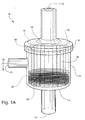
- the membrane contactor 10 generally includes a housing 12, a stack 26 of membrane mats 28, a cap 20, and a potting material 32 (See Figures 1a, 2a and 3a).
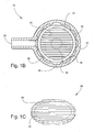
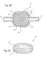
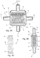
- Housing 12 may be a generally cup shaped housing with a closed end 14, and an open end 16 (see Figures 1a, 2a and 3a). Housing 12 may be sized to receive stack 26 of membrane mats 28. A potting material 32 may divide housing 12 into an internal chamber 34 and at least one external chamber 36. Housing 12 may be made of any material, including, metal, plastic, or composite. Preferably, housing 12 may be a molded piece. Housing 12 may, for example, be fabricated from a rigid FDA grade material, such as polycarbonate. Housing 12 may be of any shape, including, cylindrical ( Figure 1a and 1b), Double 'D' (Figure 2a and 2b), and rectangular ( Figure (3a and 3b).
- Cap 20 may be united to open end 16 of housing 12 (see Figures 1a, 2a and 3a). Cap 20 may be for closing housing 12. An inlet port 22 (figures 1a and 2a) or side port 24 (figure 3a) may be included in Cap 20.
- cap 20 includes a generally truncated open-ended cone. Cap 20 may include an annular grove for allowing air flow through all of headspace 56. After stack 26 may be inserted into housing 12, cap 20 may be united to housing 12. Preferably, cap 20 may be united by an air-tight seal to the exterior walls of housing 12. Such sealing means may include gluing, welding, spin welding, threading, O-rings, and the like.
- An inlet port 22 and an outlet port 18 may be included in membrane , contactor 10 (see Figures 1a, 2a and 3a). Closed end 14 may include outlet port 18 for receiving a liquid into housing 12. Cap 20 may include inlet port 22 for discharging the liquid from housing 12. Inlet port 22 and outlet port 18 may be in communication with internal chamber 34. In combination, inlet port 22 and outlet port 18, may allow a fluid to be moved through housing 12 in internal chamber 34. Inlet port 22 and outlet port 18 may be reversible allowing fluid to flow through membrane contactor 10 in either direction. Additionally, inlet port 22 and outlet port 18 may be provided with detachable couplings for coupling the membrane contactor 10 to a fluid system. The detachable coupling may include quick-connect fitting, threaded fittings, compression fittings, twist-lock fittings, Luer fitting, or other fittings for connection to a fluid line.
- At least one side port 24 may be provided in housing 12 (see Figures 1a, 2a and 3a). Side ports 24 may be between open end 16 and closed end 14 (see Figures 1a and 2a). Alternatively, side ports 24 may be included in cap 20 and closed end 14 (see Figure 3a). Side ports 24 may be in communication with external chambers 36. Side ports 24 may be for providing a vacuum or partial vacuum to external chambers 36 or may be for sweeping a gas through housing 12 from one external chamber 36 to another external chamber 36. Preferably, there should be one side port 24 positioned at the center of every external chamber 36 (see Figures 1 b, 2b, and 3b).
- each side port 24 may be provided with a detachable fitting including, but not limited to, quick-connect fittings, threaded fittings, compression fittings, twist-lock fittings, Luer fitting, or other fittings for connection to a vacuum line, gas line or fluid line.
- a detachable fitting including, but not limited to, quick-connect fittings, threaded fittings, compression fittings, twist-lock fittings, Luer fitting, or other fittings for connection to a vacuum line, gas line or fluid line.
- Stack 26 may be inserted into housing 12 (see Figures 1a, 2a, and 3a). The stack 26 of membrane mats 28 is sandwiched between closed end 14 and cap 20. Stack 26 may include a plurality of membrane mats 28. Potting material 32 may bond stack 26 together and hold stack 26 in place in housing 12. Membrane mats 28 may be stacked so that hollow fiber members 30 of each membrane mat 28 are aligned allowing a gas to be swept through membrane contactor 10. Membrane mats 28 may also be stacked so that hollow fiber members 30 of every other membrane mat 28 are perpendicularly aligned allowing a gas to be swept through in two different directions in membrane contactor 10 or allowing two different gases to be swept through membrane contactor 10.
- Membrane mats 28 may be stacked in housing 12 (see Figures 1a, 2a and 3a).
- the membrane mats 28 may be woven, knitted, or otherwise joined together in generally planar structures containing a plurality of joined together hollow fiber members 30.
- Membrane mats 28 are shown with exaggerated hollow fiber members 30 in Figures 1c, 2c and 3c.
- Membrane mats 28 may be stacked substantially perpendicular to the longitudinal axis of housing 12. The dimension of membrane mats 28 may be slightly smaller than housing 12 so that when stack 26 may be inserted into housing 12 a headspace 56 may be created between the peripheral wall of stack 26 and the interior wall of housing 12 (see figures 1b, 2b and 3b).
- Membrane mats 28 may be cut to any shape, including but not limited to, circular (see Figure 1c), Double 'D' shaped (see Figure 2c) or rectangular (see Figure 3c). Membrane mats 28 may also be cut into strips. These strips may be folded, wound up, etc. to form a rectangular cross section of stack 26 (see Figure 3c). These strips of membrane mats 28 being folded, wound up, etc. may allow membrane contactor 10 to be smaller because the strips may hold together better and may prevent loose ends.
- Hollow fiber members 30 may be included in membrane mats 28 (see Figures 1c, 2c and 3c). Hollow fiber members 30 may extend from internal chamber 34 through potting material 32 into external chambers 36. Hollow fiber members 30 may be for communicating between internal chamber 34 and external chamber 36 allowing removal of entrained gases from a liquid, debubbling of a liquid, filtering of a liquid, or adding a gas to a liquid. Hollow fiber members 30 of membrane mats 28 may be of like materials and properties, or may be of various materials and/or properties. Hollow fiber members 30 may be fibers having a lumen and a wall surrounding the lumen.
- Hollow fiber members 30 may have solid walls, porous walls, or microporous walls (e.g., symmetric pores, asymmetric pores, skinned membranes and the like). Hollow fiber members 30 may be made of any suitable FDA grade materials. Such materials include polyolefins (e.g., polyethylene, polypropylene, polybutene, poly methyl pentene), polysulfones (e.g., polysulfone, polyethersulfone, polyarylsulfone), cellulose and its derivations, PVDF, poly phenyl oxide (PPO), PFAA, PTFE, other fluorinated polymers, polyamides, polyether imides (PEI), polyimides, ion-exchange membranes (e.g., Nafion®), etc.
- polyolefins e.g., polyethylene, polypropylene, polybutene, poly methyl pentene
- polysulfones e.g., polysulfone,
- Potting material 32 may be for providing a fluid-tight annular wall within membrane contactor 10 (see Figures 1b, 2b and 3b). Potting material 32 may be a fluid-tight annular wall (see Figure 1b) or partial annular walls (see Figures 2b and 3b) that divide housing 12 into an internal chamber 34 and at least one external chamber 36. The fluid-tight annular wall or partial annular walls defined by potting material 32 may be bonded to the closed end 14 and cap 20, and may be further continuous or integral through stack 26 between membrane mats 28. This may allow potting material 32 to distribute the strength of the device to housing 12 and cap 20. Potting material 32 may maintain a fluid-tight engagement between housing 12 and the stack 26 of membrane mats 28 between closed end 14 and cap 20. Potting material 32 may be any material, for example, any suitable FDA grade thermosetting materials or any suitable FDA grade thermoplastic materials. Exemplary materials for potting material 32 include, but are not limited to, epoxy, polyolefins, and polyurethane.
- Internal chamber 34 may be divided by potting material 32 from external chambers 36 within housing 12 (see Figures 1b, 2b and 3b). Internal chamber 34 may be in communication with inlet port 22 and outlet port 18. Internal chamber 34 may be for allowing a fluid to move through stack 26 in membrane contactor 10.
- At least one external chamber 36 may be included in housing 12 (see Figures 1b, 2b and 3b). External chambers 36 may be for providing a space for the peripheral edge of stack 26 where the ends of hollow fiber members 30 may remain open. A headspace 56 may be included in external chambers 36. External chambers 36 may allow hollow fiber members 30 to communicate from internal chamber 34 through plotting material 32 to headspace 56.
- Headspace 56 may be included within external chambers 36 (see Figures 1b, 2b and 3b). Headspace 56 may be defined by the space between the peripheral walls of stack 26 and the interior surface of housing 12. Headspace 56 may allow communication between side ports 24 and the open ends of the hollow fiber members 30 of the membrane mats 28. Headspace 56 may include a plurality of baffles 38.
- Baffles 38 may be included in headspace 56 (see Figures 1b and 2b). Baffles 38 may be for centering stack 26 within housing 12. Baffles 38 may also be for facilitating air flow through headspace 56. Baffles 38 may be any structures that center stack 26 within housing 12 or that facilitate air flow through headspace 56. Baffles 38 may be positioned longitudinally, on the inner wall of housing 12.
- membrane contactor 10 may be used to remove entrained gases from a fluid, debubble a fluid, filter a fluid, or add gas to a liquid.
- a fluid may be introduced into membrane contactor 10 via inlet port 22 and exit via outlet port 18 (or vice versa).
- gases may be removed (entrained gases or bubbles) or added, and unwanted materials may be blocked (filtration).
- the characteristics of the hollow fiber will change.
- the gases may be removed by passing through the wall of the hollow fiber members 30, into the lumen, and out through side ports 24 by way of headspace 56. Removal of the gases may be facilitated by application of a vacuum or partial vacuum by way of side ports 24. Removal of the gases may also be facilitated by sweeping a gas through membrane contactor 10 by way of side ports 24. Gases that may be swept through membrane contactor 10 by way of side ports 24 to facilitate removal of gases from a liquid include, but are not limited to, carbon dioxide, nitrogen, oxygen, etc.. When membrane contactor 10 may have more than one side port 24, ambient air may also be used in facilitating removal of gases from a liquid.
- One side port 24 may be left open while the other side ports 24 are hooked up to a vacuum line.
- ambient air from outside of membrane contactor 10 may be swept through membrane contactor 10. Sweeping a gas through membrane contactor 10, like carbon dioxide, may also facilitate removal of any condensation buildup in membrane contactor 10.
- gases such as carbon dioxide, nitrogen, oxygen, etc.
- gases may be introduced into a fluid.
- the gas may be introduced through side ports 24 at a lower pressure than the liquid in internal chamber 34.
- the lower pressure allows the gas to absorb into the liquid, which may reduce bubbling of the gas in the liquid.
- Gas may then move from side ports 24 to headspace 56 and into hollow fiber lumens and out through the wall of the hollow fiber members 30 into the fluid.
- Gas in side ports 24 may be introduced into the fluid by supplying gas to side ports 24 at a pressure. This pressure may be low, thus, allowing the gas to absorb into the liquid which reduces bubbling of the gas in the liquid.
- contaminated fluid is introduced via inlet port 22 or outlet port 18 and exits via side ports 24 (or vice versa). Fluid travels through the hollow fiber members 30 from internal chamber 34 to the external chambers 36 and the walls of the hollow fiber members 30 block contaminants.
- the membrane contactor 10 may provide several performance enhancements over other devices when used in removing entrained gases from liquids, or debubbling liquids. Because of its design, membrane contactor 10 may provide a less restrictive flow path from inlet port 22 to outlet port 18, which results in less pressure drop in the fluid moving through internal chamber 36. The less the pressure drop is in external chamber 36, the less effect membrane contactor 10 has on the fluid system. Membrane contactor 10 may be designed with more hollow fiber members 30 that are shorter instead of fewer long hollow fiber members 30. These shorter hollow fiber members 30 may result in less pressure drop in the hollow fiber members 30, which may provide better performance in membrane contactor 10 when used in removing entrained gases or debubbling a liquid. As a result of these enhanced performances, membrane contactor 10 may provide greater performance than a device with an equivalent amount of membrane area.
- the membrane contactor 10 is manufactured as follows:
- housing 12 may be filled with stack 26 of membrane mats 28.
- Membrane mats 28 may be dimensioned to almost fill the cavity of housing 12 and may be stacked so that they are substantially perpendicular to the longitudinal axis of housing 12.
- Housing 12 and cap 20 may be made of any material. Such materials include polyolefins, polyvinyl chloride, ABS, Noryl®, PVDF, PFA, or other fluorinated plastics, fiber-reinforced plastics, polysulfones, polycarbonates, polyamides, metals, etc.
- the membrane mats 28 may be woven, knitted, or otherwise joined together in generally planar structures containing a plurality of joined together hollow fiber members 30.
- the hollow fiber members 30 of the membrane mats 28 may be of like materials and properties, or may be of various materials and/or properties.
- These membrane mats 28 may be cut from a larger fabric to the desired size and shape to fit within housing 12. Cutting may be accomplished by die cutting, ultrasonic cutting, knife cutting (e.g., hot), etc.
- Hollow fiber members 30 may be fibers having a lumen and a wall surrounding the lumen. Hollow fiber members 30 may have solid walls, porous walls, or microporous walls (e.g., symmetric pores, asymmetric pores, skinned membranes and the like). These hollow fibers may be made of any material.
- Such materials include polyolefins (e.g., polyethylene, polypropylene, polybutene, poly methyl pentene), polysulfones (e.g., polysulfone, polyethersulfone, polyarylsulfone), cellulose and its derivations, PVDF, poly phenyl oxide (PPO), PFAA, PTFE, other fluorinated polymers, polyamides, polyether imides (PEI), polyimides, ion-exchange membranes (e.g, Nafion®), etc.
- polyolefins e.g., polyethylene, polypropylene, polybutene, poly methyl pentene
- polysulfones e.g., polysulfone, polyethersulfone, polyarylsulfone
- cellulose and its derivations PVDF, poly phenyl oxide (PPO), PFAA, PTFE, other fluorinated polymers, polyamides, polyether im
- Cap 20 may be placed over open end 16 of housing 12 after stack 26 may be inserted into housing 12. Cap 20 may be united to housing 12. This uniting may be accomplished by any means, for example, gluing, welding, or threading. Cap 20 may be joined along its contact surface with housing 12. The housing 12 and cap 20 sandwich the stack 26 of membrane mats 28 and hold the mats in place during the next operation of the manufacture process.
- plugging of side ports 24 may be done to maintain the fluids in housing 12 when housing 12 is spun in the following steps. Plugging of side ports 24 may be done by any device, including but not limited to, a cork, a plug, a stopper, a cap, etc.
- the housing 12 and cap 20 may be mounted via outlet port 18 or inlet port 22 onto a device that can spin the membrane contactor 10 about the center longitudinal axis of housing 12.
- a boundary fluid is introduced into either outlet port 18 or inlet port 22.
- the boundary fluid by action of centrifugal force, runs to the interior wall of housing 12 thereby forming a boundary wall or partial boundary walls (depending on the shape of housing 12).
- the boundary wall may provide a space for the peripheral edge of stack 26 (external chambers 36), thus, keeping the ends of hollow fiber members 30 open at all steps of the manufacturing process.
- Potting material 32 may be introduced into either outlet port 18 or inlet port 22 after the boundary fluid is inserted.
- the potting material 32 by action of centrifugal forces, runs to the interior walls of housing 12. Because the boundary fluid may be inert to potting material 32 and may be denser than potting material 32, potting material 32 thereby forms an annular ring or partial annular ring (depending on the shape of housing 12) against the boundary wall. Spinning is preferably stopped when potting material 32 has had sufficient time to solidify to a point that it will no longer run or substantially run (i.e., retains or substantially retains the shape of the annular wall).
- Potting material 32 may be any material, for example, thermosetting or thermoplastic materials. These materials are chosen with the following exemplary considerations: bond strength to the hollow fiber members 30, housing 12 and cap 20, mechanical strength, and chemical resistance. Exemplary materials for potting material 32 include, but are not limited to, epoxy and polyolefins.
- Housing 12 may be spun horizontally. Spinning speeds may be 150-5000 rpm (depending upon, for example, potting viscosity). If cure is performed at ambient temperatures, spinning till substantially no flow could take up to 24 hours; but, if cure is at higher temperatures, then cure times may be shortened, for example at 50°C, spinning time could be dropped to 2 hours, and at 65°C, spinning time to 0.5 - 0.75 hours.
- side ports 24 may be opened. This step allows the boundary fluid to be emptied. Emptying of the boundary fluid may be facilitated by spinning housing 12 as in the previous step after side ports 24 are opened. Once the boundary fluid is emptied, membrane contactor 10 may be in its final form.
- This manufacturing process provides many advantages over the current processes. This process may eliminate the need to machine the embedded stacks after potting and may eliminate any steps of assembly. Thus, this process may significantly reduce the time and costs of manufacturing. Also, since there is no machining after potting, the risk of contaminants getting into the device may be reduced. With this process, there are only two molded parts needed to produce the device, thus, making the device very simple. Since the product ends up being a single integral device there are minimal hold-up volumes available for the fluid. There are also no dead spots. Another advantage is that this process provides a product where the strength of the potting material 32 may be reinforced by housing 12, because the potting material 32 not only is bonded to the membrane mats 28 but also to housing 12. Also, the size of membrane contactor 10 may be relatively small since clearance for assembly is not required and the device is reduced to the bare essentials.
- housing 12 is shown in final form and has a cylindrical shape.
- Headspace 56 is defined between the peripheral wall of stack 26 and the interior surface of housing 12. Because housing 12 has a cylindrical shape, the boundary fluid formed a single annular boundary wall during spinning, and potting material 32 formed a complete annular ring up against the annular boundary wall. This produces a single external chamber 36 around the entire potting material 32 and allows for a single side port 24 to communicate with all of headspace 56 (see Figure 1b).
- housing 12 is shown in final form and has a Double 'D' shape.
- Headspace 56 is defined between the peripheral wall of stack 26 and the interior surface of housing 12. Because housing 12 has a Double 'D' shape, the boundary fluid formed two partial annular boundary walls during spinning, and potting material 32 formed two partial annular rings up against the annular boundary walls. This produces two external chambers 36 around the potting material 32 and requires two side ports 24 to communicate with all of headspace 56 (see Figure 2b).
- This embodiment allows a gas to be swept through membrane contactor 10 by providing two separate external chambers 36.
- housing 12 is shown in final form and has a rectangular shape.
- Headspace 56 is defined between the peripheral wall of stack 26 and the interior surface of housing 12. Because housing 12 has a rectangular shape, the boundary fluid formed two partial annular boundary walls during spinning, and potting material 32 formed two partial annular rings up against the annular boundary walls. This produces two external chambers 36 around the potting material 32 and requires two side ports 24 to communicate with all of headspace 56 (see Figure 3b).
- This embodiment allows a gas to be swept through membrane contactor 10 by providing two separate external chambers 36. Also, because housing 12 is rectangular, this embodiment allows membrane contactor 10 to be narrow, allowing it to operate in smaller spaces.
Landscapes
- Chemical & Material Sciences (AREA)
- Chemical Kinetics & Catalysis (AREA)
- Engineering & Computer Science (AREA)
- Manufacturing & Machinery (AREA)
- Separation Using Semi-Permeable Membranes (AREA)
- Degasification And Air Bubble Elimination (AREA)
- Physical Water Treatments (AREA)
Applications Claiming Priority (1)
| Application Number | Priority Date | Filing Date | Title |
|---|---|---|---|
| US11/447,188 US7641795B2 (en) | 2006-06-05 | 2006-06-05 | Membrane contactor |
Related Child Applications (1)
| Application Number | Title | Priority Date | Filing Date |
|---|---|---|---|
| EP11152294.2 Division-Into | 2011-01-27 |
Publications (3)
| Publication Number | Publication Date |
|---|---|
| EP1864709A2 true EP1864709A2 (fr) | 2007-12-12 |
| EP1864709A3 EP1864709A3 (fr) | 2008-10-29 |
| EP1864709B1 EP1864709B1 (fr) | 2011-08-03 |
Family
ID=38523461
Family Applications (1)
| Application Number | Title | Priority Date | Filing Date |
|---|---|---|---|
| EP07010661A Active EP1864709B1 (fr) | 2006-06-05 | 2007-05-30 | Contacteur de membrane |
Country Status (5)
| Country | Link |
|---|---|
| US (1) | US7641795B2 (fr) |
| EP (1) | EP1864709B1 (fr) |
| JP (1) | JP4723536B2 (fr) |
| CN (1) | CN101121099B (fr) |
| TW (1) | TW200803961A (fr) |
Cited By (10)
| Publication number | Priority date | Publication date | Assignee | Title |
|---|---|---|---|---|
| EP2113297A1 (fr) * | 2008-04-30 | 2009-11-04 | Celgard LLC | Connecteur de membrane liquide contenue son procédé de fabrication |
| EP2296792A1 (fr) * | 2008-06-05 | 2011-03-23 | Celgard LLC | Module à fibres creuses en forme de tranche pour une utilisation en ligne dans un système de canalisation |
| US8308943B2 (en) | 2006-11-13 | 2012-11-13 | Toyota Jidosha Kabushiki Kaisha | Hollow fiber membrane module and fuel cell system |
| EP2735358A1 (fr) * | 2012-11-22 | 2014-05-28 | Gambro Lundia AB | Dialyseurs capillaires |
| WO2014183852A1 (fr) * | 2013-05-17 | 2014-11-20 | Novalung Gmbh | Module d'oxygénateur, oxygénateur et procédé de fabrication |
| EP2777801A3 (fr) * | 2013-03-15 | 2014-11-26 | Maquet Cardiopulmonary AG | Dispositif d'élimination du CO2 du sang d'un patient |
| EP2237851A4 (fr) * | 2008-01-18 | 2015-12-23 | Fresenius Med Care Hldg Inc | Elimination du dioxyde de carbone gazeux d'un circuit de fluide d'un dispositif de dialyse |
| US10486113B2 (en) | 2014-12-08 | 2019-11-26 | Technische Universität Berlin | Fluid distribution device for a gas-liquid contactor, gas-liquid contactor and method for adding a gas to a liquid |
| US10610629B2 (en) | 2015-05-07 | 2020-04-07 | Novalung Gmbh | Device with inlet portion for treating a biological liquid |
| US10898633B2 (en) | 2016-09-22 | 2021-01-26 | Michigan Critical Care Consultants, Inc. | Devices and methods for extracorporeal conditioning of blood |
Families Citing this family (30)
| Publication number | Priority date | Publication date | Assignee | Title |
|---|---|---|---|---|
| ATE423905T1 (de) * | 2005-11-09 | 2009-03-15 | Dlp Ltd | Membranpumpe |
| US7682421B2 (en) * | 2006-10-12 | 2010-03-23 | Celgard Llc | Degassing a liquid using a gravity fed apparatus |
| JP5424894B2 (ja) * | 2007-01-13 | 2014-02-26 | メムブラーナ ゲゼルシャフト ミット ベシュレンクテル ハフツング | 血液から白血球を除去するための装置 |
| JP5354248B2 (ja) * | 2008-03-05 | 2013-11-27 | Nok株式会社 | 加湿膜モジュール |
| CN104722239A (zh) * | 2008-05-19 | 2015-06-24 | 恩特格里公司 | 用于制备气体在液体中的无气泡溶液的方法和气化设备 |
| US8696626B2 (en) * | 2008-07-30 | 2014-04-15 | Claudia F. E. Kirsch | Debubbler |
| WO2010059395A1 (fr) * | 2008-10-30 | 2010-05-27 | Porous Media Corporation | Système de ventilation et de filtration avec une membrane perméable au gaz |
| US8506685B2 (en) * | 2009-08-17 | 2013-08-13 | Celgard Llc | High pressure liquid degassing membrane contactors and methods of manufacturing and use |
| US11156041B2 (en) * | 2012-02-22 | 2021-10-26 | Richard Paul Posa | System and method for treating water |
| US9821251B2 (en) | 2013-07-24 | 2017-11-21 | Mitsubishi Chemical Corporation | External-perfusion hollow-fiber membrade module and inkjet printer having said module |
| US9777237B2 (en) | 2014-11-12 | 2017-10-03 | Element 1 Corp. | Refining assemblies and refining methods for rich natural gas |
| US9605224B2 (en) | 2014-11-12 | 2017-03-28 | Element 1 Corp. | Refining assemblies and refining methods for rich natural gas |
| US9828561B2 (en) | 2014-11-12 | 2017-11-28 | Element 1 Corp. | Refining assemblies and refining methods for rich natural gas |
| KR102645537B1 (ko) * | 2015-06-22 | 2024-03-07 | 쓰리엠 이노베이티브 프로퍼티즈 컴파니 | 단일 용접 접촉기 |
| US10477883B2 (en) | 2015-08-25 | 2019-11-19 | Cornelius, Inc. | Gas injection assemblies for batch beverages having spargers |
| US10785996B2 (en) | 2015-08-25 | 2020-09-29 | Cornelius, Inc. | Apparatuses, systems, and methods for inline injection of gases into liquids |
| WO2017195818A1 (fr) | 2016-05-11 | 2017-11-16 | 三菱ケミカル・クリンスイ株式会社 | Module de membranes à fibres creuses |
| CN108114673A (zh) * | 2016-11-29 | 2018-06-05 | 中国科学院大连化学物理研究所 | 一种中空纤维膜接触反应器及在气液两相反应中的应用 |
| AU2018221143A1 (en) * | 2017-02-17 | 2019-07-25 | Bayer Aktiengesellschaft | Degassing in methods for continuous processing of a healthcare product |
| EP3363517A1 (fr) * | 2017-02-17 | 2018-08-22 | Bayer Healthcare LLC | Dégazage dans des procédés de production en continu d'un produit de soins de santé |
| CN106902552A (zh) * | 2017-03-10 | 2017-06-30 | 艾迪机器(杭州)有限公司 | 一种移动厕所粪污集输装置 |
| WO2018195534A1 (fr) | 2017-04-21 | 2018-10-25 | New Jersey Institute Of Tecgnology | Module à membrane à fibres creuses pour dessalement par distillation à membrane à contact direct |
| US10870810B2 (en) | 2017-07-20 | 2020-12-22 | Proteum Energy, Llc | Method and system for converting associated gas |
| US10758844B2 (en) * | 2017-07-25 | 2020-09-01 | Hamilton Sundstrand Corporation | Fluid degassing devices having selected profiles |
| US11040314B2 (en) | 2019-01-08 | 2021-06-22 | Marmon Foodservice Technologies, Inc. | Apparatuses, systems, and methods for injecting gasses into beverages |
| CN110052060B (zh) * | 2019-04-24 | 2022-07-01 | 杭州科百特过滤器材有限公司 | 一种中空纤维脱气膜组件 |
| CN110354685A (zh) * | 2019-06-14 | 2019-10-22 | 浙江启尔机电技术有限公司 | 一种用于光刻设备的气液分离装置 |
| US11541157B2 (en) | 2019-06-18 | 2023-01-03 | Michigan Critical Care Consultants, Inc. | Membrane oxygenator with gas exchange fiber lumen access based on fiber effective length |
| US20240091712A1 (en) * | 2019-10-10 | 2024-03-21 | Nanyang Technological University | Reverse osmosis apparatus and method thereof |
| BR102019024938A2 (pt) * | 2019-11-26 | 2021-06-08 | Petróleo Brasileiro S.A. - Petrobras | vaso de alta pressão para acondicionamento de membranas de tipo fibras ocas para o processo de separação com contactores |
Citations (2)
| Publication number | Priority date | Publication date | Assignee | Title |
|---|---|---|---|---|
| US5174900A (en) | 1989-03-24 | 1992-12-29 | The Standard Oil Company | Apparatus for separation and for treatment of fluid feedstreams, wafers for use therein and related methods |
| WO2000006357A1 (fr) | 1998-07-28 | 2000-02-10 | Terumo Cardiovascular Systems Corporation | Encapsulation de faisceaux d'elements tubulaires dans un logement |
Family Cites Families (7)
| Publication number | Priority date | Publication date | Assignee | Title |
|---|---|---|---|---|
| US4959152A (en) * | 1989-03-24 | 1990-09-25 | The Standard Oil Company | Hollow fiber separation module and method for the use thereof |
| US5000855A (en) | 1989-07-21 | 1991-03-19 | The Standard Oil Company | Transverse sheet membrane separation module, components thereof and related methods |
| JPH05184879A (ja) | 1991-07-05 | 1993-07-27 | Akzo Nv | ガス状媒体から液状媒体へかつ/またはこの逆に物質移動を行うための装置 |
| ATE300349T1 (de) | 2000-05-05 | 2005-08-15 | Zenon Environmental Inc | Gelvergussverfahren zur herstellung von hohlfaserfiltermembranen |
| AU2002343599A1 (en) * | 2001-11-02 | 2003-05-19 | Millipore Corporation | Membrane adsorber device |
| WO2003051495A1 (fr) | 2001-12-18 | 2003-06-26 | Filterwerk Mann+Hummel Gmbh | Procede de production d'un module membrane a fibres creuses, dispositif de production d'un module membrane a fibres creuses et module membrane a fibres creuses |
| US7628916B2 (en) * | 2005-01-26 | 2009-12-08 | Celgard Llc | Hollow fiber module |
-
2006
- 2006-06-05 US US11/447,188 patent/US7641795B2/en active Active
-
2007
- 2007-05-23 TW TW096118401A patent/TW200803961A/zh unknown
- 2007-05-30 EP EP07010661A patent/EP1864709B1/fr active Active
- 2007-06-04 JP JP2007147686A patent/JP4723536B2/ja active Active
- 2007-06-05 CN CN2007101104046A patent/CN101121099B/zh active Active
Patent Citations (2)
| Publication number | Priority date | Publication date | Assignee | Title |
|---|---|---|---|---|
| US5174900A (en) | 1989-03-24 | 1992-12-29 | The Standard Oil Company | Apparatus for separation and for treatment of fluid feedstreams, wafers for use therein and related methods |
| WO2000006357A1 (fr) | 1998-07-28 | 2000-02-10 | Terumo Cardiovascular Systems Corporation | Encapsulation de faisceaux d'elements tubulaires dans un logement |
Cited By (16)
| Publication number | Priority date | Publication date | Assignee | Title |
|---|---|---|---|---|
| US8308943B2 (en) | 2006-11-13 | 2012-11-13 | Toyota Jidosha Kabushiki Kaisha | Hollow fiber membrane module and fuel cell system |
| EP2237851A4 (fr) * | 2008-01-18 | 2015-12-23 | Fresenius Med Care Hldg Inc | Elimination du dioxyde de carbone gazeux d'un circuit de fluide d'un dispositif de dialyse |
| EP2113297A1 (fr) * | 2008-04-30 | 2009-11-04 | Celgard LLC | Connecteur de membrane liquide contenue son procédé de fabrication |
| US7803274B2 (en) | 2008-04-30 | 2010-09-28 | Celgard Llc | Contained liquid membrane contactor and a method of manufacturing the same |
| EP2296792A1 (fr) * | 2008-06-05 | 2011-03-23 | Celgard LLC | Module à fibres creuses en forme de tranche pour une utilisation en ligne dans un système de canalisation |
| EP2296792A4 (fr) * | 2008-06-05 | 2012-08-15 | Celgard Llc | Module à fibres creuses en forme de tranche pour une utilisation en ligne dans un système de canalisation |
| EP2735358A1 (fr) * | 2012-11-22 | 2014-05-28 | Gambro Lundia AB | Dialyseurs capillaires |
| WO2014079991A1 (fr) * | 2012-11-22 | 2014-05-30 | Gambro Lundia Ab | Dialyseurs à capillaires |
| EP2777801A3 (fr) * | 2013-03-15 | 2014-11-26 | Maquet Cardiopulmonary AG | Dispositif d'élimination du CO2 du sang d'un patient |
| US10201649B2 (en) | 2013-03-15 | 2019-02-12 | MAQUET CARDIOPULMONARY GmbH | Carbon dioxide removal system |
| WO2014183852A1 (fr) * | 2013-05-17 | 2014-11-20 | Novalung Gmbh | Module d'oxygénateur, oxygénateur et procédé de fabrication |
| US10286137B2 (en) | 2013-05-17 | 2019-05-14 | Novalung Gmbh | Oxygenator module, oxygenator and production method |
| EP2996796B1 (fr) | 2013-05-17 | 2020-12-09 | novalung GmbH | Oxygénateur et son utilisation |
| US10486113B2 (en) | 2014-12-08 | 2019-11-26 | Technische Universität Berlin | Fluid distribution device for a gas-liquid contactor, gas-liquid contactor and method for adding a gas to a liquid |
| US10610629B2 (en) | 2015-05-07 | 2020-04-07 | Novalung Gmbh | Device with inlet portion for treating a biological liquid |
| US10898633B2 (en) | 2016-09-22 | 2021-01-26 | Michigan Critical Care Consultants, Inc. | Devices and methods for extracorporeal conditioning of blood |
Also Published As
| Publication number | Publication date |
|---|---|
| US20070278145A1 (en) | 2007-12-06 |
| EP1864709B1 (fr) | 2011-08-03 |
| CN101121099B (zh) | 2010-06-23 |
| TW200803961A (en) | 2008-01-16 |
| US7641795B2 (en) | 2010-01-05 |
| JP2008030023A (ja) | 2008-02-14 |
| CN101121099A (zh) | 2008-02-13 |
| JP4723536B2 (ja) | 2011-07-13 |
| EP1864709A3 (fr) | 2008-10-29 |
Similar Documents
| Publication | Publication Date | Title |
|---|---|---|
| US7641795B2 (en) | Membrane contactor | |
| US7628916B2 (en) | Hollow fiber module | |
| US7264725B2 (en) | Hollow fiber membrane contactor and method of making same | |
| EP1582252B1 (fr) | Mini-contacteur à membrane en fibres creuses à trois ports et à haute performance | |
| US8158001B2 (en) | Wafer-shaped hollow fiber module for in-line use in a piping system | |
| JPH09234351A (ja) | 濾液を流すための濾液導管を区切るチューブ | |
| WO1998028065A1 (fr) | Module de type membrane a des fibres creuses et procede de fabrication | |
| EP3142769B1 (fr) | Filtre de récupération de liquide | |
| CN111514759A (zh) | 中空纤维膜模块和用于制造中空纤维膜模块的方法 | |
| JP7290208B2 (ja) | 中空糸膜モジュール | |
| US20230233998A1 (en) | Potting process and apparatus | |
| JP5385523B2 (ja) | 分離膜モジュールの製造方法 | |
| CA2308234A1 (fr) | Methode d'empotage au gel de membranes de filtration a fibres creuses | |
| JP2010247024A (ja) | 中空糸膜モジュールの製造方法 |
Legal Events
| Date | Code | Title | Description |
|---|---|---|---|
| PUAI | Public reference made under article 153(3) epc to a published international application that has entered the european phase |
Free format text: ORIGINAL CODE: 0009012 |
|
| AK | Designated contracting states |
Kind code of ref document: A2 Designated state(s): AT BE BG CH CY CZ DE DK EE ES FI FR GB GR HU IE IS IT LI LT LU LV MC MT NL PL PT RO SE SI SK TR |
|
| AX | Request for extension of the european patent |
Extension state: AL BA HR MK YU |
|
| PUAL | Search report despatched |
Free format text: ORIGINAL CODE: 0009013 |
|
| AK | Designated contracting states |
Kind code of ref document: A3 Designated state(s): AT BE BG CH CY CZ DE DK EE ES FI FR GB GR HU IE IS IT LI LT LU LV MC MT NL PL PT RO SE SI SK TR |
|
| AX | Request for extension of the european patent |
Extension state: AL BA HR MK RS |
|
| 17P | Request for examination filed |
Effective date: 20081121 |
|
| 17Q | First examination report despatched |
Effective date: 20090123 |
|
| AKX | Designation fees paid |
Designated state(s): DE FR GB IT |
|
| GRAP | Despatch of communication of intention to grant a patent |
Free format text: ORIGINAL CODE: EPIDOSNIGR1 |
|
| GRAS | Grant fee paid |
Free format text: ORIGINAL CODE: EPIDOSNIGR3 |
|
| GRAA | (expected) grant |
Free format text: ORIGINAL CODE: 0009210 |
|
| AK | Designated contracting states |
Kind code of ref document: B1 Designated state(s): DE FR GB IT |
|
| REG | Reference to a national code |
Ref country code: GB Ref legal event code: FG4D |
|
| REG | Reference to a national code |
Ref country code: DE Ref legal event code: R081 Ref document number: 602007016200 Country of ref document: DE Owner name: 3M INNOVATIVE PROPERTIES COMPANY, ST. PAUL, US Free format text: FORMER OWNER: CELGARD LLC, CHARLOTTE, N.C., US |
|
| REG | Reference to a national code |
Ref country code: DE Ref legal event code: R096 Ref document number: 602007016200 Country of ref document: DE Effective date: 20110929 |
|
| PLBE | No opposition filed within time limit |
Free format text: ORIGINAL CODE: 0009261 |
|
| STAA | Information on the status of an ep patent application or granted ep patent |
Free format text: STATUS: NO OPPOSITION FILED WITHIN TIME LIMIT |
|
| 26N | No opposition filed |
Effective date: 20120504 |
|
| REG | Reference to a national code |
Ref country code: DE Ref legal event code: R097 Ref document number: 602007016200 Country of ref document: DE Effective date: 20120504 |
|
| REG | Reference to a national code |
Ref country code: GB Ref legal event code: 732E Free format text: REGISTERED BETWEEN 20160104 AND 20160106 |
|
| REG | Reference to a national code |
Ref country code: DE Ref legal event code: R081 Ref document number: 602007016200 Country of ref document: DE Owner name: 3M INNOVATIVE PROPERTIES COMPANY, ST. PAUL, US Free format text: FORMER OWNER: CELGARD LLC, CHARLOTTE, N.C., US |
|
| REG | Reference to a national code |
Ref country code: FR Ref legal event code: PLFP Year of fee payment: 10 |
|
| PGFP | Annual fee paid to national office [announced via postgrant information from national office to epo] |
Ref country code: GB Payment date: 20160525 Year of fee payment: 10 |
|
| REG | Reference to a national code |
Ref country code: FR Ref legal event code: TP Owner name: 3M INNOVATIVE PROPERTIES COMPANY, US Effective date: 20160715 |
|
| PGFP | Annual fee paid to national office [announced via postgrant information from national office to epo] |
Ref country code: FR Payment date: 20160412 Year of fee payment: 10 |
|
| GBPC | Gb: european patent ceased through non-payment of renewal fee |
Effective date: 20170530 |
|
| REG | Reference to a national code |
Ref country code: FR Ref legal event code: ST Effective date: 20180131 |
|
| PG25 | Lapsed in a contracting state [announced via postgrant information from national office to epo] |
Ref country code: GB Free format text: LAPSE BECAUSE OF NON-PAYMENT OF DUE FEES Effective date: 20170530 |
|
| PG25 | Lapsed in a contracting state [announced via postgrant information from national office to epo] |
Ref country code: FR Free format text: LAPSE BECAUSE OF NON-PAYMENT OF DUE FEES Effective date: 20170531 |
|
| P01 | Opt-out of the competence of the unified patent court (upc) registered |
Effective date: 20230530 |
|
| REG | Reference to a national code |
Ref country code: DE Ref legal event code: R082 Ref document number: 602007016200 Country of ref document: DE Ref country code: DE Ref legal event code: R081 Ref document number: 602007016200 Country of ref document: DE Owner name: SOLVENTUM INTELLECTUAL PROPERTIES CO. (N.D. GE, US Free format text: FORMER OWNER: 3M INNOVATIVE PROPERTIES COMPANY, ST. PAUL, MN, US |
|
| PGFP | Annual fee paid to national office [announced via postgrant information from national office to epo] |
Ref country code: DE Payment date: 20240418 Year of fee payment: 18 |
|
| PGFP | Annual fee paid to national office [announced via postgrant information from national office to epo] |
Ref country code: IT Payment date: 20240418 Year of fee payment: 18 |