EP1862823A1 - Foreign object detection system for agricultural harvesting machines - Google Patents
Foreign object detection system for agricultural harvesting machines Download PDFInfo
- Publication number
- EP1862823A1 EP1862823A1 EP07108973A EP07108973A EP1862823A1 EP 1862823 A1 EP1862823 A1 EP 1862823A1 EP 07108973 A EP07108973 A EP 07108973A EP 07108973 A EP07108973 A EP 07108973A EP 1862823 A1 EP1862823 A1 EP 1862823A1
- Authority
- EP
- European Patent Office
- Prior art keywords
- harvester
- foreign object
- crop
- feeder section
- sensor
- Prior art date
- Legal status (The legal status is an assumption and is not a legal conclusion. Google has not performed a legal analysis and makes no representation as to the accuracy of the status listed.)
- Granted
Links
- 238000001514 detection method Methods 0.000 title claims abstract description 35
- 238000003306 harvesting Methods 0.000 title description 9
- 229910052751 metal Inorganic materials 0.000 claims abstract description 28
- 239000002184 metal Substances 0.000 claims abstract description 28
- 238000001208 nuclear magnetic resonance pulse sequence Methods 0.000 claims abstract description 7
- 230000005291 magnetic effect Effects 0.000 claims description 18
- 230000005294 ferromagnetic effect Effects 0.000 claims description 7
- 239000000463 material Substances 0.000 description 13
- 239000004459 forage Substances 0.000 description 9
- 239000003302 ferromagnetic material Substances 0.000 description 6
- 230000006378 damage Effects 0.000 description 5
- 230000004907 flux Effects 0.000 description 5
- 125000006850 spacer group Chemical group 0.000 description 4
- 230000005540 biological transmission Effects 0.000 description 3
- 241000283690 Bos taurus Species 0.000 description 2
- 230000005355 Hall effect Effects 0.000 description 2
- 240000008042 Zea mays Species 0.000 description 2
- 235000016383 Zea mays subsp huehuetenangensis Nutrition 0.000 description 2
- 235000002017 Zea mays subsp mays Nutrition 0.000 description 2
- 229910000963 austenitic stainless steel Inorganic materials 0.000 description 2
- 238000005286 illumination Methods 0.000 description 2
- 235000009973 maize Nutrition 0.000 description 2
- 230000011664 signaling Effects 0.000 description 2
- CWYNVVGOOAEACU-UHFFFAOYSA-N Fe2+ Chemical compound [Fe+2] CWYNVVGOOAEACU-UHFFFAOYSA-N 0.000 description 1
- 241001124569 Lycaenidae Species 0.000 description 1
- 241001465754 Metazoa Species 0.000 description 1
- 229910000831 Steel Inorganic materials 0.000 description 1
- 239000004411 aluminium Substances 0.000 description 1
- 229910052782 aluminium Inorganic materials 0.000 description 1
- XAGFODPZIPBFFR-UHFFFAOYSA-N aluminium Chemical compound [Al] XAGFODPZIPBFFR-UHFFFAOYSA-N 0.000 description 1
- 230000007423 decrease Effects 0.000 description 1
- 230000001419 dependent effect Effects 0.000 description 1
- 230000000694 effects Effects 0.000 description 1
- 210000000936 intestine Anatomy 0.000 description 1
- 230000002093 peripheral effect Effects 0.000 description 1
- 229920002635 polyurethane Polymers 0.000 description 1
- 239000004814 polyurethane Substances 0.000 description 1
- 230000035945 sensitivity Effects 0.000 description 1
- 229910001220 stainless steel Inorganic materials 0.000 description 1
- 239000010935 stainless steel Substances 0.000 description 1
- 239000010959 steel Substances 0.000 description 1
- 210000002784 stomach Anatomy 0.000 description 1
- 230000001960 triggered effect Effects 0.000 description 1
Images


Classifications
-
- A—HUMAN NECESSITIES
- A01—AGRICULTURE; FORESTRY; ANIMAL HUSBANDRY; HUNTING; TRAPPING; FISHING
- A01D—HARVESTING; MOWING
- A01D75/00—Accessories for harvesters or mowers
- A01D75/18—Safety devices for parts of the machines
-
- B—PERFORMING OPERATIONS; TRANSPORTING
- B60—VEHICLES IN GENERAL
- B60Q—ARRANGEMENT OF SIGNALLING OR LIGHTING DEVICES, THE MOUNTING OR SUPPORTING THEREOF OR CIRCUITS THEREFOR, FOR VEHICLES IN GENERAL
- B60Q1/00—Arrangement of optical signalling or lighting devices, the mounting or supporting thereof or circuits therefor
- B60Q1/26—Arrangement of optical signalling or lighting devices, the mounting or supporting thereof or circuits therefor the devices being primarily intended to indicate the vehicle, or parts thereof, or to give signals, to other traffic
- B60Q1/50—Arrangement of optical signalling or lighting devices, the mounting or supporting thereof or circuits therefor the devices being primarily intended to indicate the vehicle, or parts thereof, or to give signals, to other traffic for indicating other intentions or conditions, e.g. request for waiting or overtaking
-
- A—HUMAN NECESSITIES
- A01—AGRICULTURE; FORESTRY; ANIMAL HUSBANDRY; HUNTING; TRAPPING; FISHING
- A01D—HARVESTING; MOWING
- A01D75/00—Accessories for harvesters or mowers
- A01D75/18—Safety devices for parts of the machines
- A01D75/187—Removing foreign objects
-
- B—PERFORMING OPERATIONS; TRANSPORTING
- B60—VEHICLES IN GENERAL
- B60Q—ARRANGEMENT OF SIGNALLING OR LIGHTING DEVICES, THE MOUNTING OR SUPPORTING THEREOF OR CIRCUITS THEREFOR, FOR VEHICLES IN GENERAL
- B60Q2800/00—Features related to particular types of vehicles not otherwise provided for
- B60Q2800/20—Utility vehicles, e.g. for agriculture, construction work
Definitions
- the present invention relates generally to agricultural harvesting machines comprising a foreign object detector in the feeder section for signalling the presence of a foreign metal object in the crop fed into the machine.
- Most metal detector sensors comprise a plurality of magnets providing magnetic flux lines extending into the crop feed path. Changes to the magnetic field are sensed by coils or Hall effect sensors which are arranged in the magnetic field, usually adjacent the magnets.
- the sensor may have an array of permanent magnets, some having a north pole and others a south pole extending towards the crop, as described in US-A-4,433,258 and US-A-5,343,676 .
- most flux lines flow from the one magnet to the other. In this manner the detection field is limited substantially to the area above the magnets.
- the sensitivity of the sensor decreases quickly with the vertical distance from the magnets, as the flux lines become less dense. As a result a small foreign object in the upper layer of the crop may pass undetected and reach the cutter head.
- a higher detection field can be realised by using magnets that all have the same polarity, as in US-A-5,504,428 and DE-A-199 12 407 .
- Such sensors are capable of detecting foreign objects in the top layers of the crop flow.
- they also are less reliable because they frequently generate false detection signals in response to vibrations or movements of components of the harvester.
- ferrous rollers or augers rotating in the vicinity of the sensor cause a substantial magnetic noise, which may include peak values exceeding the threshold value for triggering the quick stop apparatus.
- the operator may react to frequent false detections by raising the threshold value.
- the sensor arrangement also becomes less sensitive to genuine signals caused by stray metal in the crop.
- An agricultural harvesting machine comprises means for processing harvested crop material; feeder section for feeding harvested crop material to said processing means along a crop feed path; and foreign object detector means for signalling the presence of foreign objects in said harvested crop, said detector means comprising a sensor having a detection field transverse to said crop feed path and extending into at least a portion of said path.
- the sensor is substantially symmetric with respect to a direction transverse to said crop feed path; and the detector means further comprises restriction means distinct from the sensor, making the detection field asymmetric with respect to said transverse direction.
- the sensor may be installed inside a hollow feeder roll, also termed a feed roll, of the feeder section.
- a hollow feeder roll also termed a feed roll
- the detection field as generated by the sensor and restricted by the restriction means preferably extends substantially above and forward of the feeder roll.
- the detection field should rather extend substantially below and forward of this feeder roll.
- the metal detector is constructed, once the feeder section has been arrested, it is necessary for the operator of the harvester to stop the vehicle, and then to search through the crop to locate and remove the detected foreign object. Having regard to the width of the feeder section, this does not always prove to be an easy task and it is of help to provide some indication to the person looking for the foreign object of its approximate location across the width of the feeder section.
- harvester having a metal detection system capable of generating an output signal indicative of the magnitude of the perturbation of a magnetic field caused by a ferromagnetic foreign object, comprising means for comparing the output signal with at least one threshold and means for providing a visible and/or audible indication when the or each threshold is exceeded, characterised in that the or each threshold is set in dependence upon the speed of movement of the crop in the intake system of the harvester.
- the first aspect of the invention allows the speed of crop movement to be removed from the equation, enabling the detection system to provide a true indication of the size of the foreign objection.
- the size of the foreign object can be indicated to the operator visually and/or aurally. For example, if a sound is emitted, its pitch may indicate the size of the foreign object while its pulse sequence may indicate the position of the object.
- a representation on the vehicle dashboard may comprise concentric circles, which may if desired differ in colour, against a chart indicating the position of the foreign object within the feeder section.
- FIG. 1 there is shown a forage harvester having a main frame 1 on which there are mounted ground engaging traction wheels 2 and steering wheels 3.
- the forage harvester shown is equipped with a crop collecting apparatus, in the form of a row crop attachment 10, suitable for the harvesting of maize, but which can be replaced with a conventional windrow pick-up device or a conventional cutter bar attachment, depending on the type of crop to be harvested.
- the row crop attachment 10 harvests maize stalks from the field and delivers the crop material to the bite of feeder section installed in a front unit of the forage harvester.
- the feeder section comprises a forward lower feed roll 26, a smooth rear lower feed roll 27, a forward upper feed roll 20 and a rear upper feed roll 21.
- the upper and lower parts of the feeder section rotate to convey the crop material along a crop feed path in between to a cutter head 36, which is mounted within a cutter head frame 34 and comprises a plurality of knives 37, generating a cylindrical peripheral shape or profile, when the cutter head 36 is rotated.
- the knives 37 cooperate with a fixed shear bar 35 (see Figures 4 and 5) to cut the crop material to length and to project it into a blower housing 38 which is provided with a blower rotor 40.
- This rotor 40 comprises a plurality of paddles, which throw the material upwardly through a blower outlet into a discharge spout 42, which can be positioned by an operator in the cab 43 to direct the cut crop material as required, normally into a wagon which is moving alongside or behind the forage harvester.
- the forage harvester has a power plant or engine 44, which is drivingly connected to a drive shaft 52, providing motive power to a lower feed roll transmission 54 on the left hand side of the front unit.
- This transmission 54 is connected directly to the lower feed rolls 26, 27 and through a drive shaft (not shown) to the upper feed roll transmission 56, drivingly interconnecting the upper feed rolls 21, 20.
- the forage harvester is equipped with apparatus for detecting the presence of foreign objects in the crop material flowing to the rotating cutter head 36.
- the apparatus 58 in the illustrated embodiment comprises a sensor 60 installed within the forward lower feed roll 26 as shown in Figure 1. Alternatively, the sensor may be installed at any other convenient place along the path of the crop material to the cutter head 36.
- the detecting apparatus 58 illustrated is a metal detector, comprising a set of magnets 62 generating a magnetic field extending into the crop flow path and means (not shown) for sensing changes to this magnetic field, as caused by stray ferromagnetic objects in the crop flow. These sensing means may comprise coils around and/or between the magnets or Hall effect sensors above the magnets.
- the arrival of a ferromagnetic object in the detection field causes a disturbance of the magnetic field which is captured by the sensing means of the sensor 60.
- the latter then generates a signal to a microprocessor of the detection apparatus to actuate a quick stop apparatus which is mounted to the drive line to the feed rolls 20, 21, 26, 27.
- a quick stop apparatus may be of the type described in EP-A-0 821 871 , but the invention may also be used with other quick stop apparatus, operable to arrest instantly the feeder section. In this manner, the apparatus halts the crop flow before the object can reach the shear bar 35 and the rotating cutter head 36. It thereby prevents serious damage to the knives 37 and the shear bar 35. It also prevents that the cutter head 36 chops the metal to small pieces which may be ingested by the cattle together with the forage.
- the sensor 60 comprises a base plate 64 made out of ferromagnetic steel, onto which is mounted a set of six magnets 62, all having a north pole at their upper ends. Alternatively, the upper ends may be south poles.
- the magnetic flux lines depart substantially perpendicularly from the upper ends of the magnets 62 and curve forwardly and rearwardly to the area below the sensor 60.
- the four central magnets 62a are wider than the two outer magnets 62b for a more even magnetic field above the sensor 60.
- the sensor 60 has a cover 66 made out of non-ferromagnetic material, such as stainless steel.
- Sensing coils are arranged adjacent the magnets and are connected to electronic circuitry comprising an amplifier and a filter, in a box 70 below the base plate 64.
- the circuitry generates a signal which is transmitted through wiring 72 to a microprocessor in the cab 43 of the harvester.
- the empty space between the cover 66 and the magnets 62 and coils may be filled with an appropriate passive filling material, such as polyurethane for improving the durability of the sensor 60 under the vibrations of operating harvester.
- the sensor 60 is mounted by four bolts 76 to a stationary shaft portion 74, which extends over almost the full width of the feed roll 26.
- Four bushings or spacers 78 hold the sensor 60 at a small distance from the cylindrical wall 80 of the feed roll.
- This wall is made out of non-ferromagnetic material, such as austenitic stainless steel.
- the wall 80 is drivingly connected to a rotatable shaft portion 82 of the feed roll.
- the wall is mounted via a ball or roller bearing 84 to the stationary shaft portion 74.
- a rearwardly extending plate 86 is mounted underneath the sensor 60 to the stationary shaft portion 74. It has an upwardly angled rear section which ends short of the inner surface of the feed roll wall 80.
- the plate 86 has a width that is slightly greater than the width of the sensor base plate 64. It is made out of ferromagnetic material, such that it captures the rearward flux lines from the magnets 62 and thereby contains the rearward portion of the magnetic field, as schematically shown in Figure 5.
- the plate 86 may have a thickness of 3 to 5 mm.
- the stationary shaft portion 74 is made out of ferromagnetic material.
- this shaft portion equally becomes magnetised, thereby extending the magnetic detection field downwards as schematically shown in Figure 4.
- This effect may be advantageous when no metal machine components are moving through the detection field.
- the front field area may extend as far as the path of a rotating component, e.g. an auger, of the harvesting attachment 10, and the rear area may extend into the path of the knives of the cutter head knives 37. These machine components will then cause a recurring noise in the detection apparatus signal.
- the front and rear portion of the detection field can be reduced by magnetically insulating the sensor 60 from the shaft portion 74.
- This may be realised by the use of bolts 76 and spacers 78 of non-ferromagnetic material.
- the bolts may be made of austenitic stainless steel and the spacers may be made out of aluminium.
- the resulting magnetic detection field then generally takes the form shown in Figure 5.
- the field still advantageously encompasses the portion of the crop flow path in front of and above the feed roll 26, but has been reduced substantially in the other areas. In this manner, the susceptibility of the sensor 60 to noise from moving components of the feeder section and the harvesting attachment 10 is reduced dramatically.
- the resulting signal from the sensor 60 contains a substantially smaller amount of noise.
- the detection apparatus 58 comprises means, e.g. software, that automatically adapt the threshold level at which the quick stop apparatus is triggered, to the average level of the noise signal.
- the detection apparatus 58 comprises means, e.g. software, that automatically adapt the threshold level at which the quick stop apparatus is triggered, to the average level of the noise signal.
- Such system is described in EP-A-0.735.384 .
- the use of the plate 86 reduces the noise signals, and the genuine signals caused by stray metal become more distinguishable, such that the overall performance of the detection apparatus is increased.
- the description above and the drawings relate to a metal detection system that is the same as that described in GB 0518414.8 .
- Such an arrangement retains the effectiveness of the sensor in the area above the magnets 60, while reducing or eliminating the influence of machine components in the area behind and below the feed roll 26. It should however be understood that the present invention is not restricted to such a metal detection system but to the manner in which information gathered from a metal detection system can be conveyed to the vehicle operator.
- Figure 2 only shows a single circuit 70 but in a practical embodiment the feeder section is divided across its width into a plurality of regions each with its own metal detection circuit and the outputs of the different circuits are compared to determine where in the feeder section a foreign object has been detected. If for example there are four separate magnetic circuits and metal detectors, the width of the feeder section can be divided into four and a response from any one only of the detectors will indicate if the object detected falls in the first, second, third or fourth region of the feeder section.
- the magnetic circuits will in practice overlap, if only to a limited extent, to avoid any dead band between them, whereupon an equal response from, say, the first two metal detectors would indicate the presence of an object approximately one quarter of the way along the width of the feeder section.
- An aspect of the invention therefore proposes emitting a signal that is visible or audible by a person outside the cab of the vehicle, the signal being pulse encoded in order to indicate the position of the foreign object within the feeder section.
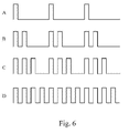
- Figure 6A to 6D of the accompanying drawing show examples of four different pulse sequences that may be used to indicate the position of the foreign object.
- the pulses in this case are emitted in groups and the number of pulses within each group is indicative of the quarter within which the foreign object is detected.
- the pulse sequence of Figure 6A may be represented by 1000_1000_1000... to signify that the object is in the first quarter.
- the pulse sequence of Figures 6B, 6C and 6D which can be represented respectively by 1100_1100_1100..., 1110_1110_1110..., and 1111_1111_11... signify that the object is in the second, third and fourth quarter, commencing the counting from a given end of the feeder section.
- Each pulse in the sequence can be emitted as a sound from the horn of the vehicle or by flashing a light such as one or both of the direction indicators.
- the pulse sequences shown in Figure 6 are, of course, only an example and one can envisage numerous alternative ways of conveying the same information to the vehicle operator. For example, if the feeder section is divided into only three regions, then flashing only one of the indicators could be used to signify that an object is near that end of the feeder section while flashing both indicators at the same time could indicate that the object is in the middle region of the feeder section.
- the magnitude of the signal generated by a metal detector could not be relied upon as a reliable indication of the size of an object as the signal would vary both with the size of the foreign object and its speed of movement through the feeder section.
- the magnitude of the detected signal is compensated for the speed of movement by setting the detection thresholds at speed dependent levels. This provides an indication of the true size of the foreign object and this information is also conveyed to the vehicle operator.
- an indication of the size of the object can be given to the vehicle operator when not in the cab by, for example, varying the pitch of the sound used to indicate the position of the foreign object.
- a low pitch may for example be used for a small body, the pitch becoming progressively more shrill as the estimated size increases.
- the group repetition frequency may be varied to provide an indication of the size of the foreign object.
Landscapes
- Life Sciences & Earth Sciences (AREA)
- Environmental Sciences (AREA)
- Engineering & Computer Science (AREA)
- Mechanical Engineering (AREA)
- Geophysics And Detection Of Objects (AREA)
- Feeding And Watering For Cattle Raising And Animal Husbandry (AREA)
Abstract
Description
- The present invention relates generally to agricultural harvesting machines comprising a foreign object detector in the feeder section for signalling the presence of a foreign metal object in the crop fed into the machine.
- It is well known in the art to provide agricultural harvesting machines, such as forage harvesters, with an apparatus for detecting foreign material in the stream of crop material which is being fed to a crop processing unit, such as a rotating cutter head cooperating with a stationary shear bar. Such apparatus may comprise a metal detector sensor as described in
US-A-4,433,528 . The signal generated by this sensor is fed to feeder arrest means, which provoke an immediate stop of the means feeding the crop material to the cutter head. In this way, stray metal objects, which may be picked up from the field, are prevented from reaching the cutter head and causing serious damage to the knives and the shear bar. Portions of damaged knives might even become detached and cause worse damage to other sections of the crop processing unit or the rest of the harvester. Small metal parts would be comminuted by the knives and mixed with the crop. When ingested by cattle, they cause serious harm to the stomachs and intestines and even cause death of the animal. The use of a foreign object detector and quick arrest apparatus prevents such injuries. - Most metal detector sensors comprise a plurality of magnets providing magnetic flux lines extending into the crop feed path. Changes to the magnetic field are sensed by coils or Hall effect sensors which are arranged in the magnetic field, usually adjacent the magnets. The sensor may have an array of permanent magnets, some having a north pole and others a south pole extending towards the crop, as described in
US-A-4,433,258 andUS-A-5,343,676 . Herein most flux lines flow from the one magnet to the other. In this manner the detection field is limited substantially to the area above the magnets. However, the sensitivity of the sensor decreases quickly with the vertical distance from the magnets, as the flux lines become less dense. As a result a small foreign object in the upper layer of the crop may pass undetected and reach the cutter head. - A higher detection field can be realised by using magnets that all have the same polarity, as in
US-A-5,504,428 andDE-A-199 12 407 . Such sensors are capable of detecting foreign objects in the top layers of the crop flow. However, it has been experienced that they also are less reliable because they frequently generate false detection signals in response to vibrations or movements of components of the harvester. For instance ferrous rollers or augers rotating in the vicinity of the sensor cause a substantial magnetic noise, which may include peak values exceeding the threshold value for triggering the quick stop apparatus. The operator may react to frequent false detections by raising the threshold value. As a result the sensor arrangement also becomes less sensitive to genuine signals caused by stray metal in the crop. - In co-pending
GB Patent Application No. 0518414.8 - An agricultural harvesting machine according to
GB 0518414.7 - The sensor may be installed inside a hollow feeder roll, also termed a feed roll, of the feeder section. In case the sensor is installed in a roll below the crop feed path, the detection field as generated by the sensor and restricted by the restriction means preferably extends substantially above and forward of the feeder roll. In case the sensor is installed in a roll above the crop feed path, the detection field should rather extend substantially below and forward of this feeder roll.
- Regardless of the manner in which the metal detector is constructed, once the feeder section has been arrested, it is necessary for the operator of the harvester to stop the vehicle, and then to search through the crop to locate and remove the detected foreign object. Having regard to the width of the feeder section, this does not always prove to be an easy task and it is of help to provide some indication to the person looking for the foreign object of its approximate location across the width of the feeder section.
- To help in locating a foreign object, it is known to provide a plurality of metal detectors spread across the width of the feeder section so that the approximate location of the object can be determined by the comparing the individual responses of the individual metal detectors. However, though information may be available to the metal detection system as to the location of a foreign object, a suitable way is required of conveying this information to an operator standing outside the vehicle cab and searching for the detected foreign objection.
- In accordance with a first aspect of the invention, there is provided harvester having a metal detection system capable of generating an output signal indicative of the magnitude of the perturbation of a magnetic field caused by a ferromagnetic foreign object, comprising means for comparing the output signal with at least one threshold and means for providing a visible and/or audible indication when the or each threshold is exceeded, characterised in that the or each threshold is set in dependence upon the speed of movement of the crop in the intake system of the harvester.
- Because a metal detection system is sensitive to the rate of change of magnetic field, its response will vary not only with the size of the foreign object but also its rate of movement through the detection system. By varying the detection threshold with the speed of crop movement, the first aspect of the invention allows the speed of crop movement to be removed from the equation, enabling the detection system to provide a true indication of the size of the foreign objection.
- It is preferable to provide three thresholds and four size ranges.
- The size of the foreign object can be indicated to the operator visually and/or aurally. For example, if a sound is emitted, its pitch may indicate the size of the foreign object while its pulse sequence may indicate the position of the object.
- A representation on the vehicle dashboard, may comprise concentric circles, which may if desired differ in colour, against a chart indicating the position of the foreign object within the feeder section.
- It would be further advantageous if the operator searching for the foreign object could be given some indication of its size.
- The invention will now be described further, by way of example, with reference to the accompanying drawings, in which:
- Figure 1 is a schematic side elevation of a forage harvester, comprising a feed roll equipped with a sensor of a foreign object detector;
- Figure 2 is a sectional view of the feed roll and the sensor of Figure 1;
- Figure 3 is a cross sectional view of the feed roll and the sensor of Figure 2;
- Figure 4 is a schematic representation of the detection field of the sensor of Figure 3 without the improvement of the present invention;
- Figure 5 is a schematic representation of the detection field of the sensor of Figure 3 using the improvement of the present invention,
- Figure 6 shows a possible form of pulse encoding.
- The terms "front" "rear" "forward", "rearward", "right" and "left" used throughout this specification are determined with respect to the normal direction of movement of the machine in operation. However they are not to be construed as limiting terms.
- In Figure 1, there is shown a forage harvester having a main frame 1 on which there are mounted ground engaging traction wheels 2 and
steering wheels 3. The forage harvester shown is equipped with a crop collecting apparatus, in the form of arow crop attachment 10, suitable for the harvesting of maize, but which can be replaced with a conventional windrow pick-up device or a conventional cutter bar attachment, depending on the type of crop to be harvested. Therow crop attachment 10 harvests maize stalks from the field and delivers the crop material to the bite of feeder section installed in a front unit of the forage harvester. - The feeder section comprises a forward
lower feed roll 26, a smooth rearlower feed roll 27, a forwardupper feed roll 20 and a rearupper feed roll 21. The upper and lower parts of the feeder section rotate to convey the crop material along a crop feed path in between to acutter head 36, which is mounted within a cutter head frame 34 and comprises a plurality of knives 37, generating a cylindrical peripheral shape or profile, when thecutter head 36 is rotated. - During normal harvesting operation, when the
cutter head 36 is rotated in its normal operation sense, as indicated by arrow F in Figure 1, the knives 37 cooperate with a fixed shear bar 35 (see Figures 4 and 5) to cut the crop material to length and to project it into ablower housing 38 which is provided with ablower rotor 40. Thisrotor 40 comprises a plurality of paddles, which throw the material upwardly through a blower outlet into adischarge spout 42, which can be positioned by an operator in thecab 43 to direct the cut crop material as required, normally into a wagon which is moving alongside or behind the forage harvester. - The forage harvester has a power plant or
engine 44, which is drivingly connected to adrive shaft 52, providing motive power to a lowerfeed roll transmission 54 on the left hand side of the front unit. Thistransmission 54 is connected directly to thelower feed rolls feed roll transmission 56, drivingly interconnecting theupper feed rolls - The forage harvester is equipped with apparatus for detecting the presence of foreign objects in the crop material flowing to the rotating
cutter head 36. Theapparatus 58 in the illustrated embodiment comprises asensor 60 installed within the forwardlower feed roll 26 as shown in Figure 1. Alternatively, the sensor may be installed at any other convenient place along the path of the crop material to thecutter head 36. The detectingapparatus 58 illustrated is a metal detector, comprising a set ofmagnets 62 generating a magnetic field extending into the crop flow path and means (not shown) for sensing changes to this magnetic field, as caused by stray ferromagnetic objects in the crop flow. These sensing means may comprise coils around and/or between the magnets or Hall effect sensors above the magnets. - The arrival of a ferromagnetic object in the detection field causes a disturbance of the magnetic field which is captured by the sensing means of the
sensor 60. The latter then generates a signal to a microprocessor of the detection apparatus to actuate a quick stop apparatus which is mounted to the drive line to the feed rolls 20, 21, 26, 27. Such quick stop apparatus may be of the type described inEP-A-0 821 871 , but the invention may also be used with other quick stop apparatus, operable to arrest instantly the feeder section. In this manner, the apparatus halts the crop flow before the object can reach the shear bar 35 and therotating cutter head 36. It thereby prevents serious damage to the knives 37 and the shear bar 35. It also prevents that thecutter head 36 chops the metal to small pieces which may be ingested by the cattle together with the forage. - As shown in Figure 2, the
sensor 60 comprises abase plate 64 made out of ferromagnetic steel, onto which is mounted a set of sixmagnets 62, all having a north pole at their upper ends. Alternatively, the upper ends may be south poles. The magnetic flux lines depart substantially perpendicularly from the upper ends of themagnets 62 and curve forwardly and rearwardly to the area below thesensor 60. The fourcentral magnets 62a are wider than the twoouter magnets 62b for a more even magnetic field above thesensor 60. Thesensor 60 has acover 66 made out of non-ferromagnetic material, such as stainless steel. Sensing coils (not shown) are arranged adjacent the magnets and are connected to electronic circuitry comprising an amplifier and a filter, in abox 70 below thebase plate 64. The circuitry generates a signal which is transmitted throughwiring 72 to a microprocessor in thecab 43 of the harvester. The empty space between thecover 66 and themagnets 62 and coils may be filled with an appropriate passive filling material, such as polyurethane for improving the durability of thesensor 60 under the vibrations of operating harvester. - Because of the alignment of the
magnets 62 on thebase plate 64, their distribution over thefull sensor 60 is substantially symmetric with respect to its longitudinal direction, i.e., the direction transverse to the crop flow. When removed from the harvester and in the absence of ferromagnetic materials, thesensor 60 produces a substantially symmetric magnetic field, extending as far forwardly as rearwardly. A cross section of the resulting field is schematically shown in Figure 4. - The
sensor 60 is mounted by fourbolts 76 to astationary shaft portion 74, which extends over almost the full width of thefeed roll 26. Four bushings orspacers 78 hold thesensor 60 at a small distance from thecylindrical wall 80 of the feed roll. This wall is made out of non-ferromagnetic material, such as austenitic stainless steel. At one side, thewall 80 is drivingly connected to arotatable shaft portion 82 of the feed roll. On the other side, the wall is mounted via a ball orroller bearing 84 to thestationary shaft portion 74. - As best shown in Figure 3, a rearwardly extending
plate 86 is mounted underneath thesensor 60 to thestationary shaft portion 74. It has an upwardly angled rear section which ends short of the inner surface of thefeed roll wall 80. Theplate 86 has a width that is slightly greater than the width of thesensor base plate 64. It is made out of ferromagnetic material, such that it captures the rearward flux lines from themagnets 62 and thereby contains the rearward portion of the magnetic field, as schematically shown in Figure 5. Theplate 86 may have a thickness of 3 to 5 mm. - Commonly, also the
stationary shaft portion 74 is made out of ferromagnetic material. When thesensor 60 is mounted thereto byferromagnetic bolts 76 and/orspacers 78, this shaft portion equally becomes magnetised, thereby extending the magnetic detection field downwards as schematically shown in Figure 4. This effect may be advantageous when no metal machine components are moving through the detection field. However, the front field area may extend as far as the path of a rotating component, e.g. an auger, of theharvesting attachment 10, and the rear area may extend into the path of the knives of the cutter head knives 37. These machine components will then cause a recurring noise in the detection apparatus signal. - The addition of the
ferromagnetic plate 86 to thedetection apparatus 58 already substantially reduces the rear and lower portion of the detection field, such that it keeps clear of the knife path. The front and rear portion of the detection field can be reduced by magnetically insulating thesensor 60 from theshaft portion 74. This may be realised by the use ofbolts 76 andspacers 78 of non-ferromagnetic material. For instance, the bolts may be made of austenitic stainless steel and the spacers may be made out of aluminium. The resulting magnetic detection field then generally takes the form shown in Figure 5. The field still advantageously encompasses the portion of the crop flow path in front of and above thefeed roll 26, but has been reduced substantially in the other areas. In this manner, the susceptibility of thesensor 60 to noise from moving components of the feeder section and theharvesting attachment 10 is reduced dramatically. - The resulting signal from the
sensor 60 contains a substantially smaller amount of noise. This is particularly advantageous, where thedetection apparatus 58 comprises means, e.g. software, that automatically adapt the threshold level at which the quick stop apparatus is triggered, to the average level of the noise signal. Such system is described inEP-A-0.735.384 . In the present arrangement, the use of theplate 86 reduces the noise signals, and the genuine signals caused by stray metal become more distinguishable, such that the overall performance of the detection apparatus is increased.
The description above and the drawings relate to a metal detection system that is the same as that described inGB 0518414.8 magnets 60, while reducing or eliminating the influence of machine components in the area behind and below thefeed roll 26. It should however be understood that the present invention is not restricted to such a metal detection system but to the manner in which information gathered from a metal detection system can be conveyed to the vehicle operator. - Figure 2 only shows a
single circuit 70 but in a practical embodiment the feeder section is divided across its width into a plurality of regions each with its own metal detection circuit and the outputs of the different circuits are compared to determine where in the feeder section a foreign object has been detected. If for example there are four separate magnetic circuits and metal detectors, the width of the feeder section can be divided into four and a response from any one only of the detectors will indicate if the object detected falls in the first, second, third or fourth region of the feeder section. The magnetic circuits will in practice overlap, if only to a limited extent, to avoid any dead band between them, whereupon an equal response from, say, the first two metal detectors would indicate the presence of an object approximately one quarter of the way along the width of the feeder section. - It is readily possible to display the position of the detected object on a display panel visible in the cab of the vehicle but such a display is not particularly convenient to a person searching in the crop present in the feeder section. An aspect of the invention therefore proposes emitting a signal that is visible or audible by a person outside the cab of the vehicle, the signal being pulse encoded in order to indicate the position of the foreign object within the feeder section.
- Figure 6A to 6D of the accompanying drawing show examples of four different pulse sequences that may be used to indicate the position of the foreign object. The pulses in this case are emitted in groups and the number of pulses within each group is indicative of the quarter within which the foreign object is detected. Hence, the pulse sequence of Figure 6A may be represented by 1000_1000_1000... to signify that the object is in the first quarter. The pulse sequence of Figures 6B, 6C and 6D, which can be represented respectively by 1100_1100_1100..., 1110_1110_1110..., and 1111_1111_1111... signify that the object is in the second, third and fourth quarter, commencing the counting from a given end of the feeder section. Each pulse in the sequence can be emitted as a sound from the horn of the vehicle or by flashing a light such as one or both of the direction indicators.
- The pulse sequences shown in Figure 6 are, of course, only an example and one can envisage numerous alternative ways of conveying the same information to the vehicle operator. For example, if the feeder section is divided into only three regions, then flashing only one of the indicators could be used to signify that an object is near that end of the feeder section while flashing both indicators at the same time could indicate that the object is in the middle region of the feeder section.
- It is also of assistance to the vehicle operator to have some indication of the size of the object that is to be located. Hitherto, the magnitude of the signal generated by a metal detector could not be relied upon as a reliable indication of the size of an object as the signal would vary both with the size of the foreign object and its speed of movement through the feeder section.
In another aspect of the present invention, the magnitude of the detected signal is compensated for the speed of movement by setting the detection thresholds at speed dependent levels. This provides an indication of the true size of the foreign object and this information is also conveyed to the vehicle operator. - In order to display the information on a display panel within the camp of the harvester, it is possible to use an image of the feeder section divided into the appropriate number of regions corresponding to the number of separate metal detectors and to light up within a region within which a foreign object has been detected a set of preferably four concentric circles representing the estimated size of the foreign object. Illumination of the innermost circle alone would indicate a small object while illumination of all the circles would indicate a large object. The concentric circles may if desired be of different colour to assist in distinguishing the different size thresholds than they represent from one another.
- If desired, an indication of the size of the object can be given to the vehicle operator when not in the cab by, for example, varying the pitch of the sound used to indicate the position of the foreign object. A low pitch may for example be used for a small body, the pitch becoming progressively more shrill as the estimated size increases.
- If flashing lights are used to indicate the position of a foreign object in a manner proposed in Figure 6, then the group repetition frequency may be varied to provide an indication of the size of the foreign object.
Claims (7)
- A harvester having a metal detection system (58) capable of generating an output signal indicative of the magnitude of the perturbation of a magnetic field caused by a ferromagnetic foreign object, comprising means for comparing the output signal with at least one threshold and means for providing a visible and/or audible indication when the or each threshold is exceeded, characterised in that the or each threshold is set in dependence upon the speed of movement of the crop in the intake system (34) of the harvester.
- A harvester as claimed in claim 1, wherein a plurality of thresholds is set to divide detected foreign objects in at least two size ranges.
- A harvester as claimed in claim 1 or 2, wherein the detected foreign objects are divided in four size ranges.
- A harvester as claimed in any of the claims 1 to 3, having a screen located within a cab (43) of the harvester on which a representation of a detected foreign object is graphically displayed.
- A harvester as claimed in claim 4, wherein a detected object is displayed on the screen by illuminating one or more of a set of concentric circles against a chart indicating the position of the foreign object within the feeder section.
- A harvester as claimed in any of the claims 1 to 5, further comprising means for visually and/or aurally indicating the estimated size of a foreign object to an operator located outside a cab (43) of the vehicle.
- A harvester as claimed in any of the claims 1 to 6, wherein the means for providing a visible and/or audible indication is mounted externally from the harvester for emitting at least an audible or a visible pulsed signal of which the pulse sequence is encoded to indicate the position of a detected foreign object in the feeder section for resolving the position of a metal foreign object across the width of the feeder section of the harvester.
Priority Applications (1)
| Application Number | Priority Date | Filing Date | Title |
|---|---|---|---|
| EP08171146.7A EP2040096B1 (en) | 2006-05-30 | 2007-05-25 | Foreign object detection system for agricultural harvesting machines |
Applications Claiming Priority (1)
| Application Number | Priority Date | Filing Date | Title |
|---|---|---|---|
| GB0610530A GB2438578A (en) | 2006-05-30 | 2006-05-30 | Metal object detection system for harvester |
Related Child Applications (1)
| Application Number | Title | Priority Date | Filing Date |
|---|---|---|---|
| EP08171146.7A Division EP2040096B1 (en) | 2006-05-30 | 2007-05-25 | Foreign object detection system for agricultural harvesting machines |
Publications (2)
| Publication Number | Publication Date |
|---|---|
| EP1862823A1 true EP1862823A1 (en) | 2007-12-05 |
| EP1862823B1 EP1862823B1 (en) | 2009-07-29 |
Family
ID=36687833
Family Applications (2)
| Application Number | Title | Priority Date | Filing Date |
|---|---|---|---|
| EP07108973A Active EP1862823B1 (en) | 2006-05-30 | 2007-05-25 | Foreign object detection system for agricultural harvesting machines |
| EP08171146.7A Active EP2040096B1 (en) | 2006-05-30 | 2007-05-25 | Foreign object detection system for agricultural harvesting machines |
Family Applications After (1)
| Application Number | Title | Priority Date | Filing Date |
|---|---|---|---|
| EP08171146.7A Active EP2040096B1 (en) | 2006-05-30 | 2007-05-25 | Foreign object detection system for agricultural harvesting machines |
Country Status (5)
| Country | Link |
|---|---|
| US (1) | US20070277491A1 (en) |
| EP (2) | EP1862823B1 (en) |
| AT (1) | ATE438110T1 (en) |
| DE (1) | DE602007001723D1 (en) |
| GB (1) | GB2438578A (en) |
Cited By (1)
| Publication number | Priority date | Publication date | Assignee | Title |
|---|---|---|---|---|
| EP3438348A1 (en) * | 2017-07-31 | 2019-02-06 | Honda Motor Co., Ltd. | Working machine |
Families Citing this family (7)
| Publication number | Priority date | Publication date | Assignee | Title |
|---|---|---|---|---|
| GB2479566A (en) * | 2010-04-15 | 2011-10-19 | Agco Int Gmbh | Braking system for a rotating chopper drum of a forage harvester |
| US20150156970A1 (en) * | 2011-01-05 | 2015-06-11 | Zharylkasyn Sadykov | Crop threshing method |
| BE1021124B1 (en) * | 2013-01-18 | 2016-01-11 | Cnh Industrial Belgium Nv | DETECTION EQUIPMENT FOR DETECTING A STRANGE OBJECT FOR A HARVESTING MACHINE. |
| US9774208B2 (en) | 2013-06-10 | 2017-09-26 | Cellco Partnership | NFC assisted wireless charging |
| US9973038B2 (en) * | 2013-06-10 | 2018-05-15 | Celico Partnership | Self optimizing antenna for NFC and wireless charging |
| US20170235009A1 (en) * | 2016-02-11 | 2017-08-17 | Glenn Curtis Arrant | Metal detector using coils with multiple detection zones to identify targets while moving |
| CN111841730B (en) * | 2020-07-15 | 2021-09-28 | 广西财经学院 | Automatic feeding type branch crusher |
Citations (5)
| Publication number | Priority date | Publication date | Assignee | Title |
|---|---|---|---|---|
| DE3332578A1 (en) * | 1983-09-09 | 1985-03-28 | B. Strautmann & Söhne GmbH u. Co, 4518 Bad Laer | Indicator for metals in fodder swaths |
| US4531118A (en) | 1983-08-29 | 1985-07-23 | Dickey-John Corporation | Metal detector |
| FR2700661A1 (en) * | 1993-01-22 | 1994-07-29 | Claas Ohg | Device for detecting foreign bodies, for a thresher |
| US5504428A (en) * | 1994-09-16 | 1996-04-02 | Deere & Company | Magnetic metal detector mounted in a feed roll of a harvisting machine |
| DE19620526A1 (en) * | 1996-05-22 | 1997-11-27 | Burkhard Weis | Metal detector for sensing ferromagnetic metal in harvesting machine |
Family Cites Families (24)
| Publication number | Priority date | Publication date | Assignee | Title |
|---|---|---|---|---|
| GB518414A (en) | 1937-09-10 | 1940-02-27 | Air Equipement | Improvements in retractable landing gear for aircraft |
| US2896190A (en) * | 1956-09-17 | 1959-07-21 | Hoda Corp | Audible flashing safety turn signals for vehicles |
| US3982237A (en) * | 1975-02-28 | 1976-09-21 | Rixson-Firemark, Inc. | Combination door chime and particulate products of combustion detector |
| JPS56131233A (en) | 1980-03-18 | 1981-10-14 | Hitachi Ltd | Logic circuit |
| US4433528A (en) | 1982-08-30 | 1984-02-28 | Sperry Corporation | Metal detector apparatus |
| US4626849A (en) * | 1983-07-29 | 1986-12-02 | Sims John C | Proximity detection system |
| DD247118A3 (en) * | 1985-10-04 | 1987-07-01 | Fortschritt Veb K | FOREIGN BODY DETECTION DEVICE FOR AGRICULTURAL HARVEST MACHINES |
| DD255432A3 (en) * | 1985-12-24 | 1988-04-06 | Fortschritt Veb K | DEVICE FOR PROTECTION FROM METALLIC FOREIGN BODIES |
| US4805385A (en) * | 1987-12-29 | 1989-02-21 | Ford New Holland, Inc. | Variable sensitivity metal detection system |
| DE4140812A1 (en) | 1991-12-11 | 1993-06-17 | Claas Saulgau Gmbh | DEVICE FOR DETECTING FERROMAGNETIC FOREIGN BODIES, ESPECIALLY IN HARVESTING MACHINES |
| US5347261A (en) * | 1993-01-21 | 1994-09-13 | Robert Adell | "Hands free" vehicle bright light signal system |
| US5600941A (en) * | 1995-03-31 | 1997-02-11 | New Holland North America, Inc. | Compensation for start-up transients |
| US5600942A (en) | 1995-03-31 | 1997-02-11 | New Holland North America, Inc. | Adaptive thresholding for metal detection |
| GB2315657A (en) | 1996-07-30 | 1998-02-11 | Ford New Holland Nv | Harvesting machines,protective arrangements |
| DE19742060B4 (en) * | 1997-09-24 | 2005-02-03 | Claas Selbstfahrende Erntemaschinen Gmbh | Foreign body recycling device on harvesting machines o. The like. |
| DE19904626C2 (en) * | 1999-02-05 | 2001-05-17 | Case Harvesting Sys Gmbh | Process for the detection of foreign bodies in harvesting machines |
| DE19912407A1 (en) | 1999-03-19 | 2000-09-21 | Deere & Co | Transporter with metal detection device for use in harvesting or chaffing machinery has a roller with magnets contained internally, the fields of which are changed by the presence of magnetic metallic parts |
| GB2348998A (en) * | 1999-04-12 | 2000-10-18 | Ford New Holland Nv | Alarm system for agricultural equipment |
| US6992771B2 (en) * | 2001-11-28 | 2006-01-31 | Battelle Memorial Institute | Systems and techniques for detecting the presence of foreign material |
| US6637179B2 (en) * | 2001-12-20 | 2003-10-28 | Kasha Farm Supplies Ltd. | Inertial system for detecting foreign objects between contra-rotating rolls |
| GB0219316D0 (en) * | 2002-08-19 | 2002-09-25 | Electronic Ltd Ab | Locating non-visible objects |
| US6933839B2 (en) * | 2003-05-16 | 2005-08-23 | John Junior Henry | Vehicle safety system |
| DE102005005736A1 (en) * | 2005-02-07 | 2006-09-28 | Claas Selbstfahrende Erntemaschinen Gmbh | Metal detection device |
| GB2430036A (en) * | 2005-09-09 | 2007-03-14 | Cnh Belgium Nv | Metal detector arrangement |
-
2006
- 2006-05-30 GB GB0610530A patent/GB2438578A/en not_active Withdrawn
-
2007
- 2007-05-15 US US11/803,498 patent/US20070277491A1/en not_active Abandoned
- 2007-05-25 EP EP07108973A patent/EP1862823B1/en active Active
- 2007-05-25 EP EP08171146.7A patent/EP2040096B1/en active Active
- 2007-05-25 DE DE602007001723T patent/DE602007001723D1/en active Active
- 2007-05-25 AT AT07108973T patent/ATE438110T1/en not_active IP Right Cessation
Patent Citations (5)
| Publication number | Priority date | Publication date | Assignee | Title |
|---|---|---|---|---|
| US4531118A (en) | 1983-08-29 | 1985-07-23 | Dickey-John Corporation | Metal detector |
| DE3332578A1 (en) * | 1983-09-09 | 1985-03-28 | B. Strautmann & Söhne GmbH u. Co, 4518 Bad Laer | Indicator for metals in fodder swaths |
| FR2700661A1 (en) * | 1993-01-22 | 1994-07-29 | Claas Ohg | Device for detecting foreign bodies, for a thresher |
| US5504428A (en) * | 1994-09-16 | 1996-04-02 | Deere & Company | Magnetic metal detector mounted in a feed roll of a harvisting machine |
| DE19620526A1 (en) * | 1996-05-22 | 1997-11-27 | Burkhard Weis | Metal detector for sensing ferromagnetic metal in harvesting machine |
Cited By (2)
| Publication number | Priority date | Publication date | Assignee | Title |
|---|---|---|---|---|
| EP3438348A1 (en) * | 2017-07-31 | 2019-02-06 | Honda Motor Co., Ltd. | Working machine |
| US10306734B2 (en) | 2017-07-31 | 2019-05-28 | Honda Motor Co., Ltd. | Working machine having lights being controlled based upon detected external environment |
Also Published As
| Publication number | Publication date |
|---|---|
| ATE438110T1 (en) | 2009-08-15 |
| EP1862823B1 (en) | 2009-07-29 |
| EP2040096A1 (en) | 2009-03-25 |
| GB2438578A (en) | 2007-12-05 |
| GB0610530D0 (en) | 2006-07-05 |
| EP2040096B1 (en) | 2016-09-14 |
| DE602007001723D1 (en) | 2009-09-10 |
| US20070277491A1 (en) | 2007-12-06 |
Similar Documents
| Publication | Publication Date | Title |
|---|---|---|
| EP2040096B1 (en) | Foreign object detection system for agricultural harvesting machines | |
| US4433528A (en) | Metal detector apparatus | |
| EP1762134B1 (en) | Metal detector arrangement | |
| US3959953A (en) | Apparatus to detect the passage of ferrous material in crop harvesting machines | |
| BE1023101B1 (en) | FOREIGN BODY DETECTION DEVICE FOR AN AGRICULTURAL HERB MACHINE. | |
| RU2389172C2 (en) | Metal detector | |
| EP1344444A1 (en) | Device for detecting the presence of a flow in a harvesting machine | |
| US4344074A (en) | Magnetic field producing apparatus | |
| GB2068549A (en) | Protective apparatus for agricultural machinery | |
| US5092818A (en) | Metal and hard object detectors with shared fixed support inside a feed roll | |
| US5444966A (en) | Metal detection apparatus for agricultural harvester | |
| RU1801303C (en) | Apparatus for detecting foreign bodies in crop material harvested by harvesting machine | |
| US7064540B2 (en) | Conveyor with a metal detecting device | |
| US20080078153A1 (en) | Foreign Body Detector For An Agricultural Harvester | |
| DE102006033100B4 (en) | Device for detecting any foreign bodies picked up by a crop intake device | |
| EP3837959B1 (en) | Agricultural tool | |
| DE19850062C2 (en) | Protective device for harvesting machines | |
| AU2017101791B4 (en) | Process Condition Monitoring Apparatus | |
| DE102005046544A1 (en) | Agricultural work unit with a work machine and a position determination unit | |
| RU2791968C1 (en) | Control unit and control system of agricultural harvesting machine and agricultural harvesting machine | |
| CN205091566U (en) | Still field is quick -witted with fault detection function | |
| JPS6349831Y2 (en) | ||
| JPS58121717A (en) | Apparatus for informing operation depth in combine | |
| CN108575278A (en) | A kind of metal detecting system and method for forage harvester | |
| CS239471B1 (en) | Apparatus for unwanted objects penetration in cutting unit |
Legal Events
| Date | Code | Title | Description |
|---|---|---|---|
| PUAI | Public reference made under article 153(3) epc to a published international application that has entered the european phase |
Free format text: ORIGINAL CODE: 0009012 |
|
| AK | Designated contracting states |
Kind code of ref document: A1 Designated state(s): AT BE BG CH CY CZ DE DK EE ES FI FR GB GR HU IE IS IT LI LT LU LV MC MT NL PL PT RO SE SI SK TR |
|
| AX | Request for extension of the european patent |
Extension state: AL BA HR MK YU |
|
| 17P | Request for examination filed |
Effective date: 20080605 |
|
| 17Q | First examination report despatched |
Effective date: 20080710 |
|
| AKX | Designation fees paid |
Designated state(s): AT BE BG CH CY CZ DE DK EE ES FI FR GB GR HU IE IS IT LI LT LU LV MC MT NL PL PT RO SE SI SK TR |
|
| GRAP | Despatch of communication of intention to grant a patent |
Free format text: ORIGINAL CODE: EPIDOSNIGR1 |
|
| GRAS | Grant fee paid |
Free format text: ORIGINAL CODE: EPIDOSNIGR3 |
|
| GRAA | (expected) grant |
Free format text: ORIGINAL CODE: 0009210 |
|
| AK | Designated contracting states |
Kind code of ref document: B1 Designated state(s): AT BE BG CH CY CZ DE DK EE ES FI FR GB GR HU IE IS IT LI LT LU LV MC MT NL PL PT RO SE SI SK TR |
|
| REG | Reference to a national code |
Ref country code: GB Ref legal event code: FG4D |
|
| REG | Reference to a national code |
Ref country code: CH Ref legal event code: EP |
|
| REG | Reference to a national code |
Ref country code: IE Ref legal event code: FG4D |
|
| REF | Corresponds to: |
Ref document number: 602007001723 Country of ref document: DE Date of ref document: 20090910 Kind code of ref document: P |
|
| NLV1 | Nl: lapsed or annulled due to failure to fulfill the requirements of art. 29p and 29m of the patents act | ||
| PG25 | Lapsed in a contracting state [announced via postgrant information from national office to epo] |
Ref country code: ES Free format text: LAPSE BECAUSE OF FAILURE TO SUBMIT A TRANSLATION OF THE DESCRIPTION OR TO PAY THE FEE WITHIN THE PRESCRIBED TIME-LIMIT Effective date: 20091109 Ref country code: LT Free format text: LAPSE BECAUSE OF FAILURE TO SUBMIT A TRANSLATION OF THE DESCRIPTION OR TO PAY THE FEE WITHIN THE PRESCRIBED TIME-LIMIT Effective date: 20090729 Ref country code: AT Free format text: LAPSE BECAUSE OF FAILURE TO SUBMIT A TRANSLATION OF THE DESCRIPTION OR TO PAY THE FEE WITHIN THE PRESCRIBED TIME-LIMIT Effective date: 20090729 Ref country code: FI Free format text: LAPSE BECAUSE OF FAILURE TO SUBMIT A TRANSLATION OF THE DESCRIPTION OR TO PAY THE FEE WITHIN THE PRESCRIBED TIME-LIMIT Effective date: 20090729 Ref country code: SE Free format text: LAPSE BECAUSE OF FAILURE TO SUBMIT A TRANSLATION OF THE DESCRIPTION OR TO PAY THE FEE WITHIN THE PRESCRIBED TIME-LIMIT Effective date: 20090729 Ref country code: IS Free format text: LAPSE BECAUSE OF FAILURE TO SUBMIT A TRANSLATION OF THE DESCRIPTION OR TO PAY THE FEE WITHIN THE PRESCRIBED TIME-LIMIT Effective date: 20091129 |
|
| PG25 | Lapsed in a contracting state [announced via postgrant information from national office to epo] |
Ref country code: NL Free format text: LAPSE BECAUSE OF FAILURE TO SUBMIT A TRANSLATION OF THE DESCRIPTION OR TO PAY THE FEE WITHIN THE PRESCRIBED TIME-LIMIT Effective date: 20090729 Ref country code: SI Free format text: LAPSE BECAUSE OF FAILURE TO SUBMIT A TRANSLATION OF THE DESCRIPTION OR TO PAY THE FEE WITHIN THE PRESCRIBED TIME-LIMIT Effective date: 20090729 Ref country code: LV Free format text: LAPSE BECAUSE OF FAILURE TO SUBMIT A TRANSLATION OF THE DESCRIPTION OR TO PAY THE FEE WITHIN THE PRESCRIBED TIME-LIMIT Effective date: 20090729 Ref country code: PL Free format text: LAPSE BECAUSE OF FAILURE TO SUBMIT A TRANSLATION OF THE DESCRIPTION OR TO PAY THE FEE WITHIN THE PRESCRIBED TIME-LIMIT Effective date: 20090729 |
|
| PG25 | Lapsed in a contracting state [announced via postgrant information from national office to epo] |
Ref country code: PT Free format text: LAPSE BECAUSE OF FAILURE TO SUBMIT A TRANSLATION OF THE DESCRIPTION OR TO PAY THE FEE WITHIN THE PRESCRIBED TIME-LIMIT Effective date: 20091129 Ref country code: BG Free format text: LAPSE BECAUSE OF FAILURE TO SUBMIT A TRANSLATION OF THE DESCRIPTION OR TO PAY THE FEE WITHIN THE PRESCRIBED TIME-LIMIT Effective date: 20091029 |
|
| PG25 | Lapsed in a contracting state [announced via postgrant information from national office to epo] |
Ref country code: EE Free format text: LAPSE BECAUSE OF FAILURE TO SUBMIT A TRANSLATION OF THE DESCRIPTION OR TO PAY THE FEE WITHIN THE PRESCRIBED TIME-LIMIT Effective date: 20090729 Ref country code: RO Free format text: LAPSE BECAUSE OF FAILURE TO SUBMIT A TRANSLATION OF THE DESCRIPTION OR TO PAY THE FEE WITHIN THE PRESCRIBED TIME-LIMIT Effective date: 20090729 Ref country code: CZ Free format text: LAPSE BECAUSE OF FAILURE TO SUBMIT A TRANSLATION OF THE DESCRIPTION OR TO PAY THE FEE WITHIN THE PRESCRIBED TIME-LIMIT Effective date: 20090729 Ref country code: DK Free format text: LAPSE BECAUSE OF FAILURE TO SUBMIT A TRANSLATION OF THE DESCRIPTION OR TO PAY THE FEE WITHIN THE PRESCRIBED TIME-LIMIT Effective date: 20090729 |
|
| PG25 | Lapsed in a contracting state [announced via postgrant information from national office to epo] |
Ref country code: SK Free format text: LAPSE BECAUSE OF FAILURE TO SUBMIT A TRANSLATION OF THE DESCRIPTION OR TO PAY THE FEE WITHIN THE PRESCRIBED TIME-LIMIT Effective date: 20090729 |
|
| PLBE | No opposition filed within time limit |
Free format text: ORIGINAL CODE: 0009261 |
|
| STAA | Information on the status of an ep patent application or granted ep patent |
Free format text: STATUS: NO OPPOSITION FILED WITHIN TIME LIMIT |
|
| 26N | No opposition filed |
Effective date: 20100503 |
|
| PG25 | Lapsed in a contracting state [announced via postgrant information from national office to epo] |
Ref country code: GR Free format text: LAPSE BECAUSE OF FAILURE TO SUBMIT A TRANSLATION OF THE DESCRIPTION OR TO PAY THE FEE WITHIN THE PRESCRIBED TIME-LIMIT Effective date: 20091030 |
|
| PG25 | Lapsed in a contracting state [announced via postgrant information from national office to epo] |
Ref country code: MC Free format text: LAPSE BECAUSE OF NON-PAYMENT OF DUE FEES Effective date: 20100531 |
|
| PG25 | Lapsed in a contracting state [announced via postgrant information from national office to epo] |
Ref country code: IT Free format text: LAPSE BECAUSE OF NON-PAYMENT OF DUE FEES Effective date: 20100525 |
|
| PG25 | Lapsed in a contracting state [announced via postgrant information from national office to epo] |
Ref country code: MT Free format text: LAPSE BECAUSE OF FAILURE TO SUBMIT A TRANSLATION OF THE DESCRIPTION OR TO PAY THE FEE WITHIN THE PRESCRIBED TIME-LIMIT Effective date: 20090729 Ref country code: IE Free format text: LAPSE BECAUSE OF NON-PAYMENT OF DUE FEES Effective date: 20100525 |
|
| REG | Reference to a national code |
Ref country code: CH Ref legal event code: PL |
|
| PG25 | Lapsed in a contracting state [announced via postgrant information from national office to epo] |
Ref country code: CH Free format text: LAPSE BECAUSE OF NON-PAYMENT OF DUE FEES Effective date: 20110531 Ref country code: LI Free format text: LAPSE BECAUSE OF NON-PAYMENT OF DUE FEES Effective date: 20110531 |
|
| PG25 | Lapsed in a contracting state [announced via postgrant information from national office to epo] |
Ref country code: CY Free format text: LAPSE BECAUSE OF FAILURE TO SUBMIT A TRANSLATION OF THE DESCRIPTION OR TO PAY THE FEE WITHIN THE PRESCRIBED TIME-LIMIT Effective date: 20090729 |
|
| PG25 | Lapsed in a contracting state [announced via postgrant information from national office to epo] |
Ref country code: LU Free format text: LAPSE BECAUSE OF NON-PAYMENT OF DUE FEES Effective date: 20100525 Ref country code: HU Free format text: LAPSE BECAUSE OF FAILURE TO SUBMIT A TRANSLATION OF THE DESCRIPTION OR TO PAY THE FEE WITHIN THE PRESCRIBED TIME-LIMIT Effective date: 20100130 |
|
| PG25 | Lapsed in a contracting state [announced via postgrant information from national office to epo] |
Ref country code: TR Free format text: LAPSE BECAUSE OF FAILURE TO SUBMIT A TRANSLATION OF THE DESCRIPTION OR TO PAY THE FEE WITHIN THE PRESCRIBED TIME-LIMIT Effective date: 20090729 |
|
| REG | Reference to a national code |
Ref country code: DE Ref legal event code: R082 Ref document number: 602007001723 Country of ref document: DE Representative=s name: PATENTANWAELTE WALLACH, KOCH & PARTNER, DE |
|
| REG | Reference to a national code |
Ref country code: DE Ref legal event code: R082 Ref document number: 602007001723 Country of ref document: DE Representative=s name: PATENTANWAELTE WALLACH, KOCH & PARTNER, DE Effective date: 20140428 Ref country code: DE Ref legal event code: R081 Ref document number: 602007001723 Country of ref document: DE Owner name: CNH INDUSTRIAL BELGIUM NV, BE Free format text: FORMER OWNER: CNH BELGIUM NV, ZEDELGEM, BE Effective date: 20140428 Ref country code: DE Ref legal event code: R082 Ref document number: 602007001723 Country of ref document: DE Representative=s name: PATENTANWAELTE WALLACH, KOCH, DR. HAIBACH, FEL, DE Effective date: 20140428 |
|
| REG | Reference to a national code |
Ref country code: FR Ref legal event code: CD Owner name: CNH INDUSTRIAL BELGIUM NV Effective date: 20140725 |
|
| REG | Reference to a national code |
Ref country code: FR Ref legal event code: PLFP Year of fee payment: 10 |
|
| REG | Reference to a national code |
Ref country code: FR Ref legal event code: PLFP Year of fee payment: 11 |
|
| PGFP | Annual fee paid to national office [announced via postgrant information from national office to epo] |
Ref country code: GB Payment date: 20170413 Year of fee payment: 11 |
|
| REG | Reference to a national code |
Ref country code: FR Ref legal event code: PLFP Year of fee payment: 12 |
|
| PGFP | Annual fee paid to national office [announced via postgrant information from national office to epo] |
Ref country code: PL Payment date: 20180427 Year of fee payment: 12 |
|
| GBPC | Gb: european patent ceased through non-payment of renewal fee |
Effective date: 20180525 |
|
| PG25 | Lapsed in a contracting state [announced via postgrant information from national office to epo] |
Ref country code: GB Free format text: LAPSE BECAUSE OF NON-PAYMENT OF DUE FEES Effective date: 20180525 |
|
| PG25 | Lapsed in a contracting state [announced via postgrant information from national office to epo] |
Ref country code: IT Free format text: LAPSE BECAUSE OF NON-PAYMENT OF DUE FEES Effective date: 20190525 |
|
| REG | Reference to a national code |
Ref country code: DE Ref legal event code: R082 Ref document number: 602007001723 Country of ref document: DE Representative=s name: MEISSNER BOLTE PATENTANWAELTE RECHTSANWAELTE P, DE |
|
| REG | Reference to a national code |
Ref country code: DE Ref legal event code: R084 Ref document number: 602007001723 Country of ref document: DE |
|
| PGFP | Annual fee paid to national office [announced via postgrant information from national office to epo] |
Ref country code: FR Payment date: 20230523 Year of fee payment: 17 |
|
| PGFP | Annual fee paid to national office [announced via postgrant information from national office to epo] |
Ref country code: BE Payment date: 20230525 Year of fee payment: 17 |
|
| PGFP | Annual fee paid to national office [announced via postgrant information from national office to epo] |
Ref country code: DE Payment date: 20240523 Year of fee payment: 18 |