EP1862739B1 - Combustion chamber for a gas turbine engine - Google Patents
Combustion chamber for a gas turbine engine Download PDFInfo
- Publication number
- EP1862739B1 EP1862739B1 EP07251864A EP07251864A EP1862739B1 EP 1862739 B1 EP1862739 B1 EP 1862739B1 EP 07251864 A EP07251864 A EP 07251864A EP 07251864 A EP07251864 A EP 07251864A EP 1862739 B1 EP1862739 B1 EP 1862739B1
- Authority
- EP
- European Patent Office
- Prior art keywords
- resonator
- neck
- combustion chamber
- cavity
- cooling
- Prior art date
- Legal status (The legal status is an assumption and is not a legal conclusion. Google has not performed a legal analysis and makes no representation as to the accuracy of the status listed.)
- Not-in-force
Links
- 238000002485 combustion reaction Methods 0.000 title claims description 50
- 238000001816 cooling Methods 0.000 claims description 29
- 238000010926 purge Methods 0.000 claims description 8
- 210000003739 neck Anatomy 0.000 description 44
- 239000007789 gas Substances 0.000 description 13
- 238000013016 damping Methods 0.000 description 7
- 238000004891 communication Methods 0.000 description 4
- 230000010355 oscillation Effects 0.000 description 4
- 230000000694 effects Effects 0.000 description 3
- 238000011144 upstream manufacturing Methods 0.000 description 3
- 230000006378 damage Effects 0.000 description 2
- 238000013461 design Methods 0.000 description 2
- 230000037406 food intake Effects 0.000 description 2
- 238000013459 approach Methods 0.000 description 1
- 239000000567 combustion gas Substances 0.000 description 1
- 239000012530 fluid Substances 0.000 description 1
- 239000000446 fuel Substances 0.000 description 1
- 238000007373 indentation Methods 0.000 description 1
- 238000002347 injection Methods 0.000 description 1
- 239000007924 injection Substances 0.000 description 1
- 238000012986 modification Methods 0.000 description 1
- 230000004048 modification Effects 0.000 description 1
- 238000013021 overheating Methods 0.000 description 1
- 230000002028 premature Effects 0.000 description 1
- 238000007789 sealing Methods 0.000 description 1
- 230000003685 thermal hair damage Effects 0.000 description 1
- 238000003466 welding Methods 0.000 description 1
Images


Classifications
-
- F—MECHANICAL ENGINEERING; LIGHTING; HEATING; WEAPONS; BLASTING
- F23—COMBUSTION APPARATUS; COMBUSTION PROCESSES
- F23R—GENERATING COMBUSTION PRODUCTS OF HIGH PRESSURE OR HIGH VELOCITY, e.g. GAS-TURBINE COMBUSTION CHAMBERS
- F23R3/00—Continuous combustion chambers using liquid or gaseous fuel
- F23R3/002—Wall structures
-
- F—MECHANICAL ENGINEERING; LIGHTING; HEATING; WEAPONS; BLASTING
- F23—COMBUSTION APPARATUS; COMBUSTION PROCESSES
- F23M—CASINGS, LININGS, WALLS OR DOORS SPECIALLY ADAPTED FOR COMBUSTION CHAMBERS, e.g. FIREBRIDGES; DEVICES FOR DEFLECTING AIR, FLAMES OR COMBUSTION PRODUCTS IN COMBUSTION CHAMBERS; SAFETY ARRANGEMENTS SPECIALLY ADAPTED FOR COMBUSTION APPARATUS; DETAILS OF COMBUSTION CHAMBERS, NOT OTHERWISE PROVIDED FOR
- F23M20/00—Details of combustion chambers, not otherwise provided for, e.g. means for storing heat from flames
- F23M20/005—Noise absorbing means
-
- F—MECHANICAL ENGINEERING; LIGHTING; HEATING; WEAPONS; BLASTING
- F23—COMBUSTION APPARATUS; COMBUSTION PROCESSES
- F23R—GENERATING COMBUSTION PRODUCTS OF HIGH PRESSURE OR HIGH VELOCITY, e.g. GAS-TURBINE COMBUSTION CHAMBERS
- F23R2900/00—Special features of, or arrangements for continuous combustion chambers; Combustion processes therefor
- F23R2900/00014—Reducing thermo-acoustic vibrations by passive means, e.g. by Helmholtz resonators
Definitions
- This invention relates to combustion chambers for gas turbine engines, and in particular lean burn, low emission combustion chambers having one or more resonator chambers for damping pressure fluctuations in the combustion chamber in use.
- Pressure oscillations in gas turbine engine combustors can be damped by using damping devices such as Helmholtz resonators, preferably in flow communication with the interior of the combustion chamber or the gas flow region surrounding the combustion chamber.
- Helmholtz resonators has been proposed in a number of earlier published patents including for example US-A-5,644,918 where a plurality of resonators are connected to the head end, that is to say the upstream end, of the flame tubes of an industrial gas turbine engine combustor.
- This type of arrangement is particularly suitable for industrial gas turbine engines where there is sufficient space at the head of the combustor to install such damping devices.
- the combustor in a ground based engine application can be made sufficiently strong to support the resonators and the vibration loads generated by the resonators in use. This arrangement is not practicable for use in aero engine applications where space, particularly in the axial direction of the engine, is more limited and component weight is a significant design consideration.
- EP1605209 and US5373695 describe Helmholtz resonator suitable for use with combustion chambers. Each resonator is provided with one or more holes that ensure the resonator cavity may be flushed with cooler air to prevent the egress of combustion gasses from the combustor and damage to the resonator itself.
- Helmholtz resonator that is particularly suitable for a combustion chamber for aero engine applications is described in EP 1,434,006A2 .
- the arrangement provides at least one Helmholtz resonator having a resonator cavity and a neck in flow communication with the interior of the combustion chamber, the neck having at least one cooling hole extending through the wall thereof.
- the cooling hole directs a film of cooling air on the inner surface of the tube wall in the region of the combustor opening, the film protecting the tube from the effects of the high temperature combustion gasses entering and exiting the resonator neck during unstable combustor operations.
- combustor space available is often insufficient to place a conventionally structured Helmholtz resonator, which has a resonator cavity and a neck that extends therefrom.
- the limited space may require such resonators to be located away from their optimum point, or to have shortened necks, or to have resonator cavities of a volume that is not optimum for the frequency oscillation to be damped.
- the conventionally structured Helmholtz resonators are typically mounted radially inwardly of the wall of the combustion chamber and are typically mounted to the inner casing to avoid loads being transmitted to the combustion chamber itself. This positioning places the resonators close to the engine shaft where there can be problems with windage that require the resonator to be mounted within an isolating enclosure that reduces the windage effects. It will be appreciated that the isolating enclosure adds cost and weight to an engine.
- a Helmholtz resonator for use in a combustion chamber of a gas turbine engine, having a resonator cavity and a resonator neck, characterised in that the cavity extends around at least part of the neck and is spaced apart therefrom to define a cooling chamber therebetween.
- the neck and the cooling chamber are coaxial.
- the cooling chamber may be annular.
- the cooling chamber has a closed end and an open end.
- the closed end has at least one purging hole that in use directs a flow of purging air into the cavity.
- the open end may have at least one cooling hole that directs a flow of cooling air from the cooling chamber into the resonator neck.
- cooling hole refers to any type of aperture through which cooling air or other fluid can pass.
- the holes in the resonator neck closest to the combustion chamber are preferably configured for damping, the velocity and volume of the air being selected to create a shedding vortex within the combustor.
- combustion chamber used herein is used interchangeably with the term “combustor” and reference to one include reference to the other.
- the combustion section 10 of a gas turbine aero engine is illustrated with the adjacent engine parts omitted for clarity, that is the compressor section upstream of the combustor (to the left of the drawing in Figure 1 ) and the turbine section downstream of the combustion section.
- the combustion section comprises an annular type combustion chamber 12 positioned in an annular region 14 between a combustion chamber outer casing 16, which is part of the engine casing structure and radially outwards of the combustion chamber, and a combustion chamber inner casing 18, also part of the engine structure and positioned radially inwards of the combustion chamber 12.
- the inner casing 16 and outer casing 18 comprise part of the engine casing load bearing structure and the function of these components is well understood by those skilled in the art.
- the combustion chamber 12 is cantilevered at its downstream end from an annular array of nozzle guide vanes 20, one of which is shown in part in the drawing of Figure 1 .
- the combustion chamber may be considered to be a non load bearing component in the sense that it does not support any loads other than the loads acting upon it due to the pressure differential across the walls of the combustion chamber.
- the combustion chamber comprises a continuous heat shield type lining on its radially inner and outer interior surfaces.
- the lining comprises a series of heat resistant tiles 22 which are attached to the interior surface of the radially inner and outer walls of the combustor in a known manner.
- the upstream end of the combustion chamber comprises an annular end wall 24 which includes a series of circumferentially spaced apertures for receiving respective air fuel injection devices 28.
- Each Helmholtz resonator 38 comprises a box like resonator cavity 40 which is in flow communication with the interior of the combustion chamber through the resonator neck 36 which extends radially from the resonator cavity 40 into the interior 41 of the combustor.
- the resonator neck has a substantially circular cross section although tubes having cross sections other than circular may be used.
- An annular sealing member 44 is provided around the outer periphery of the tube to provide a gas tight seal between the tube and the opening 30.
- the tube provides for limited relative axial movement of the tube with respect to the combustion chamber so that substantially no load is transferred from the resonator tube to the combustion chamber during engine operation.
- the resonator is mounted on the outer wall of the combustion chamber where, as can be seen from Figure 1 , there is limited space between the combustor wall 12 and the outer casing 16.
- the neck is sunk into the cavity whilst maintaining a gap between the wall of the cavity and the wall of the resonator neck that allows cooling and purging air to be supplied to both the neck and the cavity.
- the cavity end of the neck is formed to be continuous with the wall of the cavity.
- the junctions have a fillet radius rather than a 90° angle.
- the fillet radius is not so large as to increase unduly the mass at the centre of the junction.
- the radially outer wall of the cavity is angled such that it can be located within the sloping outer wall 16 of the combustor casing.
- the resonator neck has a circular cross section with a plurality of circumferentially spaced cooling holes 54 formed in the tube wall.
- the cooling holes 54 are equally spaced around the tube circumference and are inclined with respect to respective lines tangential to the tube circumference at the hole locations.
- a single row of 20, 0.5mm diameter holes is provided, positioned in the half of the neck 36 closest to the resonator cavity and about quarter of the way along the neck from the cavity, each of the holes having an axis angled towards the resonator cavity 40.
- the angle 64 formed between the hole axis and the axis 60 of the resonator neck 36 is of the order 30°.
- the holes have a swirl angle of 45°.
- the resonator In use, the resonator is thus continually purged with cooling air passing through the array of holes 54.
- the purging air keeps the resonator cavity at a temperature at which no thermal damage occurs and beneficially creates a flow of air in the neck that travels from the cavity to the combustion chamber both cooling the neck and preventing ingestion of hot combustor gasses.
- a second row 56 of holes is provided in an axially spaced relation with the first row of holes 54, along the length of the neck and is positioned closer to the end of the neck that opens into the combustion chamber than the first row of holes 54.
- the second row of holes consists of twenty 0.5mm diameter holes.
- the holes have an axis that is angled 17° with respect to the longitudinal axis of the neck and directed towards the combustor chamber, the holes also have a swirl angle of 20°.
- the relative swirl angles create a tangential component with respect to the circumference of the tube. This promotes vortex flow on the interior surface of the tube when cooling air passes from the exterior region of the tube into the interior region thereof.
- the reduced swirl component of the holes 56 closest to the combustion chamber allows the flow of air to adhere to the inner wall of the resonator neck.
- the adherence improves the vortex shedding at the combustor opening and consequently the damping achieved by the resonator.
- the volume of the air passing through the cooling holes closest to the combustor chamber can be reduced such that the efficiency of the damper is enhanced.
- the hot gases can be induced into the resonator neck and cavity in the absence of purging holes.
- the presence of a row of holes angled towards the resonator cavity induces a flow of air into the cavity and then along the resonator neck which inhibits the flow of hot gases within the neck.
- the resonator neck and the resonator cavity may be formed as separate components and joined together.
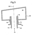
- the neck has an inner wall 72 that extends around an axis 100 and an outer wall 74 coaxial with the inner wall.
- the outer wall 74 has at one end an inwardly extending radial flange that joins the outer wall 74 with the inner wall 72 and at the other end a radially outwardly extending flange 78 that is used to connect the neck with the cavity wall 80.
- this arrangement allows resonator necks to be simply and easily changed to alter the damping characteristics of the resonator.
- an existing neck (not shown) may be removed and the new neck inserted into the aperture 82 of the cavity 40 in the direction of arrow 70.
- the flange abuts the cavity wall and may be joined by welding or more preferably through a nut and bolt type fixing (not shown).
- the outer wall 74 of the resonator neck provides one wall of the resonator cavity 40.
- a number of resonators 38 are positioned around the combustion chamber outer casing 12.
- the resonators have different circumferential dimensions such that the volume of the respective cavities 40 of the resonators is different for each resonator.
- This difference in cavity volume has the effect of ensuring each resonator has a different resonator frequency such that the respective resonators 38 compliment one another in the sense that collectively the resonators operate over a wide frequency band to damp pressure oscillations in the combustion chamber over substantially the entire running range of the engine.
- Each resonator has a particularly frequency and the resonator cavities 40 are sized such that the different resonator frequencies do not substantially overlap.
- the axial location of the resonators can be different, as can the circumferential spacing between adjacent resonators.
- Helmholtz resonators according to the invention can have both asymmetric volumes and sunken necks which enable the device to be situated in locations unsuitable for conventional Helmholtz resonators.
- the resonator cavity may be shaped to fit in and around other components and may have indentations or the such like to enable placement regardless of the location of bolts, flanges etc. on adjacent components.
Landscapes
- Engineering & Computer Science (AREA)
- Chemical & Material Sciences (AREA)
- Combustion & Propulsion (AREA)
- Mechanical Engineering (AREA)
- General Engineering & Computer Science (AREA)
- Turbine Rotor Nozzle Sealing (AREA)
- Soundproofing, Sound Blocking, And Sound Damping (AREA)
Description
- This invention relates to combustion chambers for gas turbine engines, and in particular lean burn, low emission combustion chambers having one or more resonator chambers for damping pressure fluctuations in the combustion chamber in use.
- Lean burn, low emission gas turbine engine combustors of the type now being developed for future engine applications have a tendency, under certain operating conditions, to produce audible pressure fluctuations which can cause premature structural damage to the combustion chamber and other parts of the engine. These pressure fluctuations are audible as rumble which occurs as a result of the combustion process.
- Pressure oscillations in gas turbine engine combustors can be damped by using damping devices such as Helmholtz resonators, preferably in flow communication with the interior of the combustion chamber or the gas flow region surrounding the combustion chamber.
- The use of Helmholtz resonators has been proposed in a number of earlier published patents including for example
US-A-5,644,918 where a plurality of resonators are connected to the head end, that is to say the upstream end, of the flame tubes of an industrial gas turbine engine combustor. This type of arrangement is particularly suitable for industrial gas turbine engines where there is sufficient space at the head of the combustor to install such damping devices. The combustor in a ground based engine application can be made sufficiently strong to support the resonators and the vibration loads generated by the resonators in use. This arrangement is not practicable for use in aero engine applications where space, particularly in the axial direction of the engine, is more limited and component weight is a significant design consideration. - A different approach to combustion chamber damping is therefore required for aero engine applications where space is more limited and design constraints require that the resonators are supported with respect to the combustion chamber without adding appreciably to the weight of the combustion chamber itself.
-
EP1605209 andUS5373695 describe Helmholtz resonator suitable for use with combustion chambers. Each resonator is provided with one or more holes that ensure the resonator cavity may be flushed with cooler air to prevent the egress of combustion gasses from the combustor and damage to the resonator itself. - Another form of Helmholtz resonator that is particularly suitable for a combustion chamber for aero engine applications is described in
EP 1,434,006A2 . The arrangement provides at least one Helmholtz resonator having a resonator cavity and a neck in flow communication with the interior of the combustion chamber, the neck having at least one cooling hole extending through the wall thereof. The cooling hole directs a film of cooling air on the inner surface of the tube wall in the region of the combustor opening, the film protecting the tube from the effects of the high temperature combustion gasses entering and exiting the resonator neck during unstable combustor operations. - It has now been found that at certain operating conditions the resonator body can overheat despite the presence of a cooling flow through holes in the neck of the resonator. This arises due to the movement of hot gases into, and out of, the resonator neck when pressure oscillations inside the combustor are relatively high. In addition, it is thought the holes angled towards the combustion chamber can induce a flow which draws hot combustion gases into the neck and resonator body.
- Within the combustor, as discussed above, space available is often insufficient to place a conventionally structured Helmholtz resonator, which has a resonator cavity and a neck that extends therefrom. The limited space may require such resonators to be located away from their optimum point, or to have shortened necks, or to have resonator cavities of a volume that is not optimum for the frequency oscillation to be damped.
- Because of the size of the conventionally structured Helmholtz resonators they are typically mounted radially inwardly of the wall of the combustion chamber and are typically mounted to the inner casing to avoid loads being transmitted to the combustion chamber itself. This positioning places the resonators close to the engine shaft where there can be problems with windage that require the resonator to be mounted within an isolating enclosure that reduces the windage effects. It will be appreciated that the isolating enclosure adds cost and weight to an engine.
- It is an object of the present invention to seek to provide an improved damper arrangement for a combustion chamber.
- According to the invention there is provided a Helmholtz resonator for use in a combustion chamber of a gas turbine engine, having a resonator cavity and a resonator neck, characterised in that the cavity extends around at least part of the neck and is spaced apart therefrom to define a cooling chamber therebetween.
- Preferably the neck and the cooling chamber are coaxial. The cooling chamber may be annular.
- In preferred embodiment the cooling chamber has a closed end and an open end. Preferably the closed end has at least one purging hole that in use directs a flow of purging air into the cavity. The open end may have at least one cooling hole that directs a flow of cooling air from the cooling chamber into the resonator neck.
- This arrangement provides cooling air directed at, or towards the resonator cavity. The direction of air can prevent overheating of both the resonator neck and the cavity. The arrangement resists the ingestion of hot combustor gasses into the resonator cavity. It is to be understood that the term "cooling hole" used herein refers to any type of aperture through which cooling air or other fluid can pass.
- The holes in the resonator neck closest to the combustion chamber are preferably configured for damping, the velocity and volume of the air being selected to create a shedding vortex within the combustor.
- For the avoidance of doubt the term "combustion chamber" used herein is used interchangeably with the term "combustor" and reference to one include reference to the other.
- Various embodiments of the invention will now be more particularly described, by way of example only, with reference to the accompanying drawings in which:
-
Figure 1 is an axisymmetric view of a gas turbine engine combustion chamber showing a Helmholtz resonator in flow communication with the interior of the chamber; -
Figure 2 is an enlarged view of the resonator ofFigure 1 . - Referring to
Figure 1 , thecombustion section 10 of a gas turbine aero engine is illustrated with the adjacent engine parts omitted for clarity, that is the compressor section upstream of the combustor (to the left of the drawing inFigure 1 ) and the turbine section downstream of the combustion section. The combustion section comprises an annulartype combustion chamber 12 positioned in anannular region 14 between a combustion chamberouter casing 16, which is part of the engine casing structure and radially outwards of the combustion chamber, and a combustion chamberinner casing 18, also part of the engine structure and positioned radially inwards of thecombustion chamber 12. Theinner casing 16 andouter casing 18 comprise part of the engine casing load bearing structure and the function of these components is well understood by those skilled in the art. Thecombustion chamber 12 is cantilevered at its downstream end from an annular array ofnozzle guide vanes 20, one of which is shown in part in the drawing ofFigure 1 . In this arrangement the combustion chamber may be considered to be a non load bearing component in the sense that it does not support any loads other than the loads acting upon it due to the pressure differential across the walls of the combustion chamber. - The combustion chamber comprises a continuous heat shield type lining on its radially inner and outer interior surfaces. The lining comprises a series of heat
resistant tiles 22 which are attached to the interior surface of the radially inner and outer walls of the combustor in a known manner. The upstream end of the combustion chamber comprises anannular end wall 24 which includes a series of circumferentially spaced apertures for receiving respective airfuel injection devices 28. - The radially outer wall of the combustion chamber is provided with a plurality of circumferentially spaced
apertures 30 for receiving the end part of a Helmholtzresonator resonator neck 36. Each Helmholtzresonator 38 comprises a box likeresonator cavity 40 which is in flow communication with the interior of the combustion chamber through theresonator neck 36 which extends radially from theresonator cavity 40 into theinterior 41 of the combustor. - In this embodiment the resonator neck has a substantially circular cross section although tubes having cross sections other than circular may be used. An
annular sealing member 44 is provided around the outer periphery of the tube to provide a gas tight seal between the tube and the opening 30. The tube provides for limited relative axial movement of the tube with respect to the combustion chamber so that substantially no load is transferred from the resonator tube to the combustion chamber during engine operation. - The resonator is mounted on the outer wall of the combustion chamber where, as can be seen from
Figure 1 , there is limited space between thecombustor wall 12 and theouter casing 16. To avoid the necessity of reducing the volume of the resonator cavity and / or the neck of the cavity to allow such a placement in the embodiment shown the neck is sunk into the cavity whilst maintaining a gap between the wall of the cavity and the wall of the resonator neck that allows cooling and purging air to be supplied to both the neck and the cavity. - The cavity end of the neck is formed to be continuous with the wall of the cavity. To avoid the generation of a hot spot the junctions have a fillet radius rather than a 90° angle. The fillet radius is not so large as to increase unduly the mass at the centre of the junction.
- In the embodiment shown the radially outer wall of the cavity is angled such that it can be located within the sloping
outer wall 16 of the combustor casing. - The resonator neck has a circular cross section with a plurality of circumferentially spaced
cooling holes 54 formed in the tube wall. Thecooling holes 54 are equally spaced around the tube circumference and are inclined with respect to respective lines tangential to the tube circumference at the hole locations. A single row of 20, 0.5mm diameter holes is provided, positioned in the half of theneck 36 closest to the resonator cavity and about quarter of the way along the neck from the cavity, each of the holes having an axis angled towards theresonator cavity 40. The angle 64 formed between the hole axis and the axis 60 of theresonator neck 36 is of theorder 30°. The holes have a swirl angle of 45°. In use, the resonator is thus continually purged with cooling air passing through the array ofholes 54. The purging air keeps the resonator cavity at a temperature at which no thermal damage occurs and beneficially creates a flow of air in the neck that travels from the cavity to the combustion chamber both cooling the neck and preventing ingestion of hot combustor gasses. - A
second row 56 of holes is provided in an axially spaced relation with the first row ofholes 54, along the length of the neck and is positioned closer to the end of the neck that opens into the combustion chamber than the first row ofholes 54. The second row of holes consists of twenty 0.5mm diameter holes. The holes have an axis that is angled 17° with respect to the longitudinal axis of the neck and directed towards the combustor chamber, the holes also have a swirl angle of 20°. - The relative swirl angles create a tangential component with respect to the circumference of the tube. This promotes vortex flow on the interior surface of the tube when cooling air passes from the exterior region of the tube into the interior region thereof.
- The reduced swirl component of the
holes 56 closest to the combustion chamber allows the flow of air to adhere to the inner wall of the resonator neck. The adherence improves the vortex shedding at the combustor opening and consequently the damping achieved by the resonator. Additionally, because cool air is entering the neck and the cavity from the purging holes the volume of the air passing through the cooling holes closest to the combustor chamber can be reduced such that the efficiency of the damper is enhanced. - It has been found that the hot gases can be induced into the resonator neck and cavity in the absence of purging holes. In the present embodiment, the presence of a row of holes angled towards the resonator cavity induces a flow of air into the cavity and then along the resonator neck which inhibits the flow of hot gases within the neck.
- In an alternative arrangement depicted with respect to
Figure 3 , the resonator neck and the resonator cavity may be formed as separate components and joined together. The neck has aninner wall 72 that extends around anaxis 100 and anouter wall 74 coaxial with the inner wall. Theouter wall 74 has at one end an inwardly extending radial flange that joins theouter wall 74 with theinner wall 72 and at the other end a radially outwardly extendingflange 78 that is used to connect the neck with thecavity wall 80. - Beneficially, this arrangement allows resonator necks to be simply and easily changed to alter the damping characteristics of the resonator. For example, an existing neck (not shown) may be removed and the new neck inserted into the
aperture 82 of thecavity 40 in the direction ofarrow 70. The flange abuts the cavity wall and may be joined by welding or more preferably through a nut and bolt type fixing (not shown). Theouter wall 74 of the resonator neck provides one wall of theresonator cavity 40. - In use, a number of
resonators 38 are positioned around the combustion chamberouter casing 12. The resonators have different circumferential dimensions such that the volume of therespective cavities 40 of the resonators is different for each resonator. This difference in cavity volume has the effect of ensuring each resonator has a different resonator frequency such that therespective resonators 38 compliment one another in the sense that collectively the resonators operate over a wide frequency band to damp pressure oscillations in the combustion chamber over substantially the entire running range of the engine. Each resonator has a particularly frequency and theresonator cavities 40 are sized such that the different resonator frequencies do not substantially overlap. The axial location of the resonators can be different, as can the circumferential spacing between adjacent resonators. - Although aspects of the invention have been described with reference to the embodiments shown in the accompanying drawing, it is to be understood that the invention is not limited to those precise embodiments and that various changes and modifications may be effected without further inventive skill and effort. For example, other hole configurations may be used including arrangements where the holes are arranged in several rows, in line, or staggered with respect to each other, with different diameters, number of holes and angles depending on the specific cooling requirements of the particular combustion chamber application. In addition, different shaped holes may be employed instead of substantially circular cross section holes.
- It will be appreciated that Helmholtz resonators according to the invention can have both asymmetric volumes and sunken necks which enable the device to be situated in locations unsuitable for conventional Helmholtz resonators. The resonator cavity may be shaped to fit in and around other components and may have indentations or the such like to enable placement regardless of the location of bolts, flanges etc. on adjacent components.
Claims (7)
- A Helmholtz resonator for use in a combustion chamber of a gas turbine engine, having a resonator cavity (40) and a resonator neck (36), characterised in that the cavity extends around at least part of the neck and is spaced apart therefrom to define a cooling chamber therebetween.
- A Helmholtz resonator according to claim 1, wherein the neck (36) and the cooling chamber are coaxial.
- A Helmholtz resonator according to claim 1 or claim 2, wherein the cooling chamber is annular.
- A Helmholtz resonator according to any preceding claim, wherein the cooling chamber has a closed end and an open end.
- A Helmholtz resonator according to claim 4, wherein the closed end has at least one purging hole (54) that in use directs a flow of purging air into the cavity (40).
- A Helmholtz resonator according to claim 4 or claim 5, wherein the open end has at least one cooling hole (50) that directs a flow of cooling air from the cooling chamber into the resonator neck.
- A combustion chamber (41) for a gas turbine engine comprising at least one Helmholtz resonator in accordance with any of the preceding claims.
Applications Claiming Priority (1)
| Application Number | Priority Date | Filing Date | Title |
|---|---|---|---|
| GBGB0610800.5A GB0610800D0 (en) | 2006-06-01 | 2006-06-01 | Combustion chamber for a gas turbine engine |
Publications (3)
| Publication Number | Publication Date |
|---|---|
| EP1862739A2 EP1862739A2 (en) | 2007-12-05 |
| EP1862739A3 EP1862739A3 (en) | 2008-02-20 |
| EP1862739B1 true EP1862739B1 (en) | 2011-07-06 |
Family
ID=36694733
Family Applications (1)
| Application Number | Title | Priority Date | Filing Date |
|---|---|---|---|
| EP07251864A Not-in-force EP1862739B1 (en) | 2006-06-01 | 2007-05-03 | Combustion chamber for a gas turbine engine |
Country Status (3)
| Country | Link |
|---|---|
| US (1) | US7857094B2 (en) |
| EP (1) | EP1862739B1 (en) |
| GB (1) | GB0610800D0 (en) |
Cited By (1)
| Publication number | Priority date | Publication date | Assignee | Title |
|---|---|---|---|---|
| EP2837783A1 (en) | 2013-08-14 | 2015-02-18 | Alstom Technology Ltd | Damper for combustion oscillation damping in a gas turbine |
Families Citing this family (44)
| Publication number | Priority date | Publication date | Assignee | Title |
|---|---|---|---|---|
| US20100236245A1 (en) * | 2009-03-19 | 2010-09-23 | Johnson Clifford E | Gas Turbine Combustion System |
| EP2295864B1 (en) * | 2009-08-31 | 2012-11-14 | Alstom Technology Ltd | Combustion device of a gas turbine |
| EP2299177A1 (en) * | 2009-09-21 | 2011-03-23 | Alstom Technology Ltd | Combustor of a gas turbine |
| US20110165527A1 (en) * | 2010-01-06 | 2011-07-07 | General Electric Company | Method and Apparatus of Combustor Dynamics Mitigation |
| US9127837B2 (en) * | 2010-06-22 | 2015-09-08 | Carrier Corporation | Low pressure drop, low NOx, induced draft gas heaters |
| US8973365B2 (en) * | 2010-10-29 | 2015-03-10 | Solar Turbines Incorporated | Gas turbine combustor with mounting for Helmholtz resonators |
| US8720204B2 (en) | 2011-02-09 | 2014-05-13 | Siemens Energy, Inc. | Resonator system with enhanced combustor liner cooling |
| US20130255260A1 (en) * | 2012-03-29 | 2013-10-03 | Solar Turbines Inc. | Resonance damper for damping acoustic oscillations from combustor |
| WO2013144070A1 (en) * | 2012-03-30 | 2013-10-03 | Alstom Technology Ltd | Combustion chamber seal segments equipped with damping devices |
| US20130283799A1 (en) * | 2012-04-25 | 2013-10-31 | Solar Turbines Inc. | Resonance damper for damping acoustic oscillations from combustor |
| US9068129B2 (en) | 2012-09-20 | 2015-06-30 | Exxonmobil Research And Engineering Company | Upgrading properties of asphalts with wax |
| WO2014133645A2 (en) | 2013-02-20 | 2014-09-04 | Rolls-Royce North American Technologies Inc. | Gas turbine engine having configurable bypass passage |
| US9400108B2 (en) | 2013-05-14 | 2016-07-26 | Siemens Aktiengesellschaft | Acoustic damping system for a combustor of a gas turbine engine |
| EP2816289B1 (en) * | 2013-05-24 | 2020-10-07 | Ansaldo Energia IP UK Limited | Damper for gas turbine |
| EP2816288B1 (en) * | 2013-05-24 | 2019-09-04 | Ansaldo Energia IP UK Limited | Combustion chamber for a gas turbine with a vibration damper |
| EP2860449B1 (en) * | 2013-10-09 | 2018-04-04 | Ansaldo Energia Switzerland AG | Acoustic damping device |
| EP2860451A1 (en) * | 2013-10-11 | 2015-04-15 | Alstom Technology Ltd | Combustion chamber of a gas turbine with improved acoustic damping |
| EP2881667B1 (en) * | 2013-10-11 | 2017-04-26 | General Electric Technology GmbH | Helmholtz damper with air cooled seal for a gas turbine |
| EP2865947B1 (en) * | 2013-10-28 | 2017-08-23 | Ansaldo Energia Switzerland AG | Damper for gas turbine |
| DE102013222932A1 (en) * | 2013-11-11 | 2015-05-28 | Rolls-Royce Deutschland Ltd & Co Kg | Gas turbine combustion chamber with shingle for carrying out a spark plug |
| US9389574B2 (en) * | 2014-02-27 | 2016-07-12 | Ricoh Company, Limited | Sound absorbing device, electronic device, and image forming apparatus |
| US10267523B2 (en) * | 2014-09-15 | 2019-04-23 | Ansaldo Energia Ip Uk Limited | Combustor dome damper system |
| CN107002999A (en) | 2014-12-01 | 2017-08-01 | 西门子公司 | The resonator with interchangeable gauge line for gas-turbine unit |
| EP3029377B1 (en) * | 2014-12-03 | 2018-04-11 | Ansaldo Energia Switzerland AG | Damper for a gas turbine |
| EP3048370A1 (en) | 2015-01-23 | 2016-07-27 | Siemens Aktiengesellschaft | Combustion chamber for a gas turbine engine |
| US10513984B2 (en) | 2015-08-25 | 2019-12-24 | General Electric Company | System for suppressing acoustic noise within a gas turbine combustor |
| DE102015224524A1 (en) * | 2015-12-08 | 2017-06-08 | Siemens Aktiengesellschaft | Combustion chamber with resonators |
| JP6815735B2 (en) | 2016-03-03 | 2021-01-20 | 三菱パワー株式会社 | Audio equipment, gas turbine |
| US10197275B2 (en) * | 2016-05-03 | 2019-02-05 | General Electric Company | High frequency acoustic damper for combustor liners |
| US10670271B2 (en) * | 2016-09-30 | 2020-06-02 | DOOSAN Heavy Industries Construction Co., LTD | Acoustic dampening liner cap and gas turbine combustor including the same |
| US10724739B2 (en) | 2017-03-24 | 2020-07-28 | General Electric Company | Combustor acoustic damping structure |
| US10415480B2 (en) | 2017-04-13 | 2019-09-17 | General Electric Company | Gas turbine engine fuel manifold damper and method of dynamics attenuation |
| EP3418637B1 (en) | 2017-06-20 | 2020-04-22 | General Electric Technology GmbH | Variable frequency helmholtz dampers |
| US11149948B2 (en) | 2017-08-21 | 2021-10-19 | General Electric Company | Fuel nozzle with angled main injection ports and radial main injection ports |
| US10941939B2 (en) | 2017-09-25 | 2021-03-09 | General Electric Company | Gas turbine assemblies and methods |
| US10767867B2 (en) * | 2018-03-21 | 2020-09-08 | Raytheon Technologies Corporation | Bearing support assembly |
| US11156162B2 (en) | 2018-05-23 | 2021-10-26 | General Electric Company | Fluid manifold damper for gas turbine engine |
| US11506125B2 (en) | 2018-08-01 | 2022-11-22 | General Electric Company | Fluid manifold assembly for gas turbine engine |
| CN109274348A (en) * | 2018-08-06 | 2019-01-25 | 东南大学 | Asymmetric coupled acoustic waveguide filter |
| US11174792B2 (en) | 2019-05-21 | 2021-11-16 | General Electric Company | System and method for high frequency acoustic dampers with baffles |
| US11156164B2 (en) | 2019-05-21 | 2021-10-26 | General Electric Company | System and method for high frequency accoustic dampers with caps |
| DE102020200583A1 (en) * | 2020-01-20 | 2021-07-22 | Siemens Aktiengesellschaft | Resonator ring for combustion chamber systems |
| CN114135901A (en) * | 2021-11-08 | 2022-03-04 | 中国航发四川燃气涡轮研究院 | Ablation-proof flame tube large-hole jet sleeve |
| US12234773B1 (en) * | 2022-01-18 | 2025-02-25 | Hysonic Technologies, LLC | Acoustically absorptive liners for passive control of unwanted acoustic modes in rotating detonation combustors |
Family Cites Families (20)
| Publication number | Priority date | Publication date | Assignee | Title |
|---|---|---|---|---|
| EP0576717A1 (en) * | 1992-07-03 | 1994-01-05 | Abb Research Ltd. | Gas turbine combustor |
| EP0597138B1 (en) | 1992-11-09 | 1997-07-16 | Asea Brown Boveri AG | Combustion chamber for gas turbine |
| DE4414232A1 (en) | 1994-04-23 | 1995-10-26 | Abb Management Ag | Device for damping thermoacoustic vibrations in a combustion chamber |
| US5644918A (en) * | 1994-11-14 | 1997-07-08 | General Electric Company | Dynamics free low emissions gas turbine combustor |
| DE19640980B4 (en) | 1996-10-04 | 2008-06-19 | Alstom | Device for damping thermoacoustic oscillations in a combustion chamber |
| US6464489B1 (en) * | 1997-11-24 | 2002-10-15 | Alstom | Method and apparatus for controlling thermoacoustic vibrations in a combustion system |
| DE59810347D1 (en) * | 1998-09-10 | 2004-01-15 | Alstom Switzerland Ltd | Vibration damping in combustion chambers |
| EP1423645B1 (en) * | 2001-09-07 | 2008-10-08 | Alstom Technology Ltd | Damping arrangement for reducing combustion chamber pulsations in a gas turbine system |
| EP1476699B1 (en) * | 2002-01-16 | 2013-11-13 | Alstom Technology Ltd | Combustion chamber and damper arrangement for reduction of combustion chamber pulsations in a gas turbine plant |
| GB0227842D0 (en) * | 2002-11-29 | 2003-01-08 | Rolls Royce Plc | Sealing Arrangement |
| US7832211B2 (en) * | 2002-12-02 | 2010-11-16 | Mitsubishi Heavy Industries, Ltd. | Gas turbine combustor and a gas turbine equipped therewith |
| GB2396687A (en) * | 2002-12-23 | 2004-06-30 | Rolls Royce Plc | Helmholtz resonator for combustion chamber use |
| GB0305025D0 (en) * | 2003-03-05 | 2003-04-09 | Alstom Switzerland Ltd | Method and device for efficient usage of cooling air for acoustic damping of combustion chamber pulsations |
| ITTO20031013A1 (en) * | 2003-12-16 | 2005-06-17 | Ansaldo Energia Spa | THERMO ACOUSTIC INSTABILITY DAMPING SYSTEM IN A COMBUSTOR DEVICE FOR A GAS TURBINE. |
| EP1605209B1 (en) | 2004-06-07 | 2010-08-04 | Siemens Aktiengesellschaft | Combustor with thermo-acoustic vibrations dampening device |
| KR20060015052A (en) * | 2004-08-13 | 2006-02-16 | 현대자동차주식회사 | Resonator of the car |
| GB0427147D0 (en) * | 2004-12-11 | 2005-01-12 | Rolls Royce Plc | Combustion chamber for a gas turbine engine |
| US7546739B2 (en) * | 2005-07-05 | 2009-06-16 | General Electric Company | Igniter tube and method of assembling same |
| BRPI0601716B1 (en) * | 2006-05-03 | 2018-09-25 | Empresa Brasileira De Compressores S A Embraco | acoustic filter resonator arrangement for refrigeration compressor |
| US7967106B2 (en) * | 2008-03-24 | 2011-06-28 | Ford Global Technologies | Air induction sound modification system for internal combustion engine |
-
2006
- 2006-06-01 GB GBGB0610800.5A patent/GB0610800D0/en not_active Ceased
-
2007
- 2007-05-03 EP EP07251864A patent/EP1862739B1/en not_active Not-in-force
- 2007-05-31 US US11/806,366 patent/US7857094B2/en active Active
Cited By (3)
| Publication number | Priority date | Publication date | Assignee | Title |
|---|---|---|---|---|
| EP2837783A1 (en) | 2013-08-14 | 2015-02-18 | Alstom Technology Ltd | Damper for combustion oscillation damping in a gas turbine |
| EP2837782A1 (en) | 2013-08-14 | 2015-02-18 | Alstom Technology Ltd | Damper for combustion oscillation damping in a gas turbine |
| US9970659B2 (en) | 2013-08-14 | 2018-05-15 | Ansaldo Energia Ip Uk Limited | Damper for combustion oscillation damping in a gas turbine |
Also Published As
| Publication number | Publication date |
|---|---|
| EP1862739A3 (en) | 2008-02-20 |
| US20080087019A1 (en) | 2008-04-17 |
| GB0610800D0 (en) | 2006-07-12 |
| EP1862739A2 (en) | 2007-12-05 |
| US7857094B2 (en) | 2010-12-28 |
Similar Documents
| Publication | Publication Date | Title |
|---|---|---|
| EP1862739B1 (en) | Combustion chamber for a gas turbine engine | |
| EP1669670B1 (en) | Helmholtz resonator for a combustion chamber for a gas turbine engine | |
| EP1962018B1 (en) | Combustion chamber for gas turbine engine | |
| CN102954492B (en) | For reducing the system and method for combustion dynamics in the burner | |
| US8726631B2 (en) | Dual walled combustors with impingement cooled igniters | |
| US7874138B2 (en) | Segmented annular combustor | |
| US11041625B2 (en) | Fuel nozzle with narrow-band acoustic damper | |
| EP2208933B1 (en) | Combustor assembly and cap for a turbine engine | |
| EP3290805B1 (en) | Fuel nozzle assembly with resonator | |
| US9249734B2 (en) | Combustor | |
| CN108626747A (en) | burner acoustic damping structure | |
| EP3315866B1 (en) | Combustor assembly with mounted auxiliary component | |
| KR20100061538A (en) | Secondary fuel delivery system | |
| JP6490199B2 (en) | Acoustic damping system for gas turbine engine combustors. | |
| JP2014112023A (en) | Assemblies and apparatus related to combustor cooling in turbine engines | |
| JP4274996B2 (en) | Gas turbine combustor | |
| EP2971967B1 (en) | Inverted cap igniter tube | |
| CN111836998B (en) | Double-chamber bottom of combustion chamber |
Legal Events
| Date | Code | Title | Description |
|---|---|---|---|
| PUAI | Public reference made under article 153(3) epc to a published international application that has entered the european phase |
Free format text: ORIGINAL CODE: 0009012 |
|
| AK | Designated contracting states |
Kind code of ref document: A2 Designated state(s): AT BE BG CH CY CZ DE DK EE ES FI FR GB GR HU IE IS IT LI LT LU LV MC MT NL PL PT RO SE SI SK TR |
|
| AX | Request for extension of the european patent |
Extension state: AL BA HR MK YU |
|
| PUAL | Search report despatched |
Free format text: ORIGINAL CODE: 0009013 |
|
| AK | Designated contracting states |
Kind code of ref document: A3 Designated state(s): AT BE BG CH CY CZ DE DK EE ES FI FR GB GR HU IE IS IT LI LT LU LV MC MT NL PL PT RO SE SI SK TR |
|
| AX | Request for extension of the european patent |
Extension state: AL BA HR MK YU |
|
| RIC1 | Information provided on ipc code assigned before grant |
Ipc: F23R 3/00 20060101AFI20070926BHEP Ipc: F23M 13/00 20060101ALI20080115BHEP |
|
| 17P | Request for examination filed |
Effective date: 20080403 |
|
| 17Q | First examination report despatched |
Effective date: 20080520 |
|
| AKX | Designation fees paid |
Designated state(s): DE FR GB |
|
| REG | Reference to a national code |
Ref country code: DE Ref legal event code: R079 Ref document number: 602007015617 Country of ref document: DE Free format text: PREVIOUS MAIN CLASS: F23R0003000000 Ipc: F23M0099000000 |
|
| GRAP | Despatch of communication of intention to grant a patent |
Free format text: ORIGINAL CODE: EPIDOSNIGR1 |
|
| RIC1 | Information provided on ipc code assigned before grant |
Ipc: F23M 99/00 20100101AFI20110224BHEP Ipc: F23R 3/00 20060101ALI20110224BHEP |
|
| GRAS | Grant fee paid |
Free format text: ORIGINAL CODE: EPIDOSNIGR3 |
|
| GRAA | (expected) grant |
Free format text: ORIGINAL CODE: 0009210 |
|
| AK | Designated contracting states |
Kind code of ref document: B1 Designated state(s): DE FR GB |
|
| REG | Reference to a national code |
Ref country code: GB Ref legal event code: FG4D |
|
| REG | Reference to a national code |
Ref country code: DE Ref legal event code: R096 Ref document number: 602007015617 Country of ref document: DE Effective date: 20110908 |
|
| PLBE | No opposition filed within time limit |
Free format text: ORIGINAL CODE: 0009261 |
|
| STAA | Information on the status of an ep patent application or granted ep patent |
Free format text: STATUS: NO OPPOSITION FILED WITHIN TIME LIMIT |
|
| 26N | No opposition filed |
Effective date: 20120411 |
|
| REG | Reference to a national code |
Ref country code: DE Ref legal event code: R097 Ref document number: 602007015617 Country of ref document: DE Effective date: 20120411 |
|
| REG | Reference to a national code |
Ref country code: FR Ref legal event code: PLFP Year of fee payment: 9 |
|
| PGFP | Annual fee paid to national office [announced via postgrant information from national office to epo] |
Ref country code: DE Payment date: 20150528 Year of fee payment: 9 Ref country code: GB Payment date: 20150527 Year of fee payment: 9 |
|
| PGFP | Annual fee paid to national office [announced via postgrant information from national office to epo] |
Ref country code: FR Payment date: 20150519 Year of fee payment: 9 |
|
| REG | Reference to a national code |
Ref country code: DE Ref legal event code: R119 Ref document number: 602007015617 Country of ref document: DE |
|
| GBPC | Gb: european patent ceased through non-payment of renewal fee |
Effective date: 20160503 |
|
| REG | Reference to a national code |
Ref country code: FR Ref legal event code: ST Effective date: 20170131 |
|
| PG25 | Lapsed in a contracting state [announced via postgrant information from national office to epo] |
Ref country code: FR Free format text: LAPSE BECAUSE OF NON-PAYMENT OF DUE FEES Effective date: 20160531 Ref country code: DE Free format text: LAPSE BECAUSE OF NON-PAYMENT OF DUE FEES Effective date: 20161201 |
|
| PG25 | Lapsed in a contracting state [announced via postgrant information from national office to epo] |
Ref country code: GB Free format text: LAPSE BECAUSE OF NON-PAYMENT OF DUE FEES Effective date: 20160503 |