EP1862321A1 - Thermal printer and method of controlling the same - Google Patents
Thermal printer and method of controlling the same Download PDFInfo
- Publication number
- EP1862321A1 EP1862321A1 EP07109061A EP07109061A EP1862321A1 EP 1862321 A1 EP1862321 A1 EP 1862321A1 EP 07109061 A EP07109061 A EP 07109061A EP 07109061 A EP07109061 A EP 07109061A EP 1862321 A1 EP1862321 A1 EP 1862321A1
- Authority
- EP
- European Patent Office
- Prior art keywords
- thermal
- printing
- paper sheet
- significant bit
- printing data
- Prior art date
- Legal status (The legal status is an assumption and is not a legal conclusion. Google has not performed a legal analysis and makes no representation as to the accuracy of the status listed.)
- Granted
Links
Images




Classifications
-
- B—PERFORMING OPERATIONS; TRANSPORTING
- B41—PRINTING; LINING MACHINES; TYPEWRITERS; STAMPS
- B41J—TYPEWRITERS; SELECTIVE PRINTING MECHANISMS, i.e. MECHANISMS PRINTING OTHERWISE THAN FROM A FORME; CORRECTION OF TYPOGRAPHICAL ERRORS
- B41J3/00—Typewriters or selective printing or marking mechanisms characterised by the purpose for which they are constructed
- B41J3/60—Typewriters or selective printing or marking mechanisms characterised by the purpose for which they are constructed for printing on both faces of the printing material
-
- B—PERFORMING OPERATIONS; TRANSPORTING
- B41—PRINTING; LINING MACHINES; TYPEWRITERS; STAMPS
- B41J—TYPEWRITERS; SELECTIVE PRINTING MECHANISMS, i.e. MECHANISMS PRINTING OTHERWISE THAN FROM A FORME; CORRECTION OF TYPOGRAPHICAL ERRORS
- B41J11/00—Devices or arrangements of selective printing mechanisms, e.g. ink-jet printers or thermal printers, for supporting or handling copy material in sheet or web form
- B41J11/008—Controlling printhead for accurately positioning print image on printing material, e.g. with the intention to control the width of margins
-
- B—PERFORMING OPERATIONS; TRANSPORTING
- B41—PRINTING; LINING MACHINES; TYPEWRITERS; STAMPS
- B41J—TYPEWRITERS; SELECTIVE PRINTING MECHANISMS, i.e. MECHANISMS PRINTING OTHERWISE THAN FROM A FORME; CORRECTION OF TYPOGRAPHICAL ERRORS
- B41J2/00—Typewriters or selective printing mechanisms characterised by the printing or marking process for which they are designed
- B41J2/315—Typewriters or selective printing mechanisms characterised by the printing or marking process for which they are designed characterised by selective application of heat to a heat sensitive printing or impression-transfer material
- B41J2/32—Typewriters or selective printing mechanisms characterised by the printing or marking process for which they are designed characterised by selective application of heat to a heat sensitive printing or impression-transfer material using thermal heads
- B41J2/35—Typewriters or selective printing mechanisms characterised by the printing or marking process for which they are designed characterised by selective application of heat to a heat sensitive printing or impression-transfer material using thermal heads providing current or voltage to the thermal head
- B41J2/355—Control circuits for heating-element selection
Definitions
- the present invention relates to a thermal printer that uses a thermal paper sheet having heat-sensitive layers on both surfaces thereof, and a method of controlling the same.
- a thermal paper sheet used in a thermal printer has a heat-sensitive layer on one surface thereof.
- a thermal printer prints printing data input from the outside on one surface of a thermal paper sheet by using a single thermal head.
- the printed thermal paper sheet is cut by a cutter and provided to a user.
- thermal paper sheet having heat-sensitive layers on both surfaces thereof has been recently developed.
- processing of e.g., feeding a paper sheet to an image forming portion of a photosensitive drum or a development unit to form an image on a first surface of the paper sheet, returning the paper sheet having the image formed thereon to the image forming portion while reversing the paper sheet, and forming an image of a second surface of the paper sheet by the image forming portion, as in double-side copying in a copying machine (see, e.g., Jpn. Pat. Appln. KOKAI Publication No. 233256-1997 and Jpn. Pat. Appln. KOKAI Publication No. 24082-1994 ).
- a thermal printer comprising:
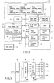
- FIG. 1 shows a structure of a primary part.
- Reference numeral 1 denotes a thermal paper sheet.
- the thermal paper sheet 1 has heat-sensitive layers on both surfaces thereof, i.e., a first surface (which will be referred to as a front surface) 1a and a second surface (which will be referred to as a rear surface) 1b, respectively.
- the thermal paper sheet 1 is rolled up in such a manner that the front surface 1a becomes an inner side, and fed in a direction indicated by an arrow in the drawing by a later-described paper feed mechanism 22.
- the heat-sensitive layer is made up of a material that is colored into, e.g., black or red when heated to a predetermined temperature or above.
- a first thermal head 2 that comes into contact with the front surface 1a of the thermal paper sheet 1 and a second thermal head 4 that comes into contact with the rear surface 1b of the same are provided along a paper feed direction of this thermal paper sheet 1.
- the first thermal head 2 has many heating elements arranged in a direction perpendicular to the paper feed direction of the thermal paper sheet 1, and prints an image corresponding to input data on the front surface 1a of the thermal paper sheet 1.
- the second thermal head 4 has many heating elements arranged in a direction perpendicular to the paper feed direction of the thermal paper sheet 1, and prints an image corresponding to input data on the rear surface 1b of the thermal paper sheet 1.
- These thermal heads 2 and 4 are arranged at positions separated from each other along the paper feed direction of the thermal paper sheet 1.
- the first thermal head 2 is arranged on a downstream side of the second thermal head 4 in the paper feed direction.
- a first platen roller 3 is arranged at a position facing the first thermal head 2, with the thermal paper sheet 1 being interposed therebetween, and a second platen roller 5 is arranged at a position facing the second thermal head 4, with the thermal paper sheet 1 being interposed therebetween. Furthermore, a cutter 6 that cuts the thermal paper sheet 1 on a rear side of a printing region is arranged on a downstream side of the first thermal head 2 in the paper feed direction.
- FIG. 2 shows a control circuit of a thermal printer main body 10 including the structure depicted in FIG. 1.
- a CPU 11 as a control section are connected an ROM 12 that stores a control program, an RAM 13 that storage data, a communication interface 14 that performs data transmission/reception with respect to a host device 30, an operating section 15 that sets operating conditions, a paper feed drive circuit 21 that drives a paper feed mechanism 16 for the thermal paper sheet 1, a cutter drive circuit 22 that drives the cutter 6, a first head controller 23 that drives and controls the first thermal head 2 in accordance with later-described first printing data D1 a second head controller 24 that drives and controls the second thermal head 4 in accordance with later-described second printing data D2, and others.
- the first thermal head 2 is constituted of a latch circuit 41, an energization control circuit 42, and an edge head 43.
- the edge head 43 has many heat-transfer heating elements 43a, 43b, ... 43n that are linearly arranged.
- the latch circuit 41 latches data serially read from a first image memory 25 in accordance with a strobe signal STB supplied from the head controller 23.
- the energization control circuit 42 controls energization with respect to the heating elements 43a, 43b, ... 43n of the edge head 43 in accordance with data in the latch circuit 41 at a timing at which an enable signal ENB supplied from the head drive circuit 23 becomes active.
- the second thermal head 4 also has the same structure as that of the first thermal head 2.
- the CPU 11 selectively controls forward printing and backward printing of the first thermal head 2 with respect to the front surface 1a of the thermal paper sheet 1, and also selectively controls forward printing and backward printing of the second thermal head 4 with respect to the rear surface 1b of the thermal paper sheet 1.
- the CPU 11 has the following means (1) to (6) as primary functions.
- the printing data D0 When the printing data D0 is input to the thermal printer main body 10 from the external host device 30, the printing data D0 is stored in the RAM 13. In accordance with this storage, the printing data D0 is divided into the first printing data D1 and the second printing data D2 based on preset conditions. The divided first printing data D1 and second printing data D2 are stored in the RAM 13 together with the printing data D0.
- feeding of the thermal paper sheet 1 is started, and driving of the second thermal head 4 is first commenced, thereby executing printing on the rear surface 1b of the thermal paper sheet 1.
- driving of the second thermal head 4 is started, thus executing printing on the front surface 1a of the thermal paper sheet 1.
- the first printing data D1 in the RAM 13 is serially read in the direction from the most significant bit (MSB) to the least significant bit (LSB) to be input to the first thermal head 2 via the first head controller 23.
- the second printing data D2 in the RAM 13 is serially read in the direction from the most significant bit (MSB) to the least significant bit (LSB) to be input to the second thermal head 4 via the second head controller 24.
- an image corresponding to the first printing data D1 is printed on the front surface 1a of the thermal paper sheet 1 in the forward direction. Furthermore, an image corresponding to the second printing data D2 is printed on the rear surface 1b of the thermal paper sheet 1 in the forward direction.
- the printed thermal paper sheet 1 is cut by the cutter 6 to be provided as, e.g., a sales receipt to a customer.
- the first printing data D1 in a time chart 13 is serially read in the direction from the least significant bit (LSB) to the most significant bit (MSB) to be input to the first thermal head 2 via the first head controller 23.
- LSB least significant bit
- MSB most significant bit
- the second printing data D2 in the RAM 13 is serially read in the direction from the most significant bit (MSB) to the least significant bit (LSB) to be input to the second thermal head 4 via the second head controller 24.
- an image corresponding to the first printing data D1 is printed on the front surface 1a of the thermal paper sheet 1 in the backward direction. Additionally, an image corresponding to the second printing data D2 is printed on the rear surface 1b of the thermal paper sheet 1 in the forward direction.
- the first printing data D1 in the RAM 13 is serially read in the direction from the most significant bit (MSB) to the least significant bit (LSB) to be input to the first thermal head 2 via the first head controller 23.
- the second printing data D2 in the RAM 13 is serially read in the direction from the least significant bit (LSB) to the most significant bit (MSB) to be input to the second thermal head 4 via the second head controller 24.
- LSB least significant bit
- MSB most significant bit
- an image corresponding to the first printing data D1 is printed on the front surface 1a of the thermal paper sheet 1 in the forward direction. Furthermore, an image corresponding to the second printing data D2 is printed on the rear surface 1b of the thermal paper sheet 1 in the backward direction.
- the first printing data D1 in the RAM 13 is serially read in the direction from the least significant bit (LSB) to the most significant bit (MSB) to be input to the first thermal head 2 via the first head controller 23.
- LSB least significant bit
- MSB most significant bit
- the second printing data D2 in the RAM 13 is serially read in the direction from the least significant bit (LSB) to the most significant bit (MSB) to be input to the second thermal head 4 via the second head controller 24.
- LSB least significant bit
- MSB most significant bit
- an image corresponding to the first printing data D1 is printed on the front surface 1a of the thermal paper sheet 1 in the backward direction.
- an image corresponding to the second printing data D2 is printed on the rear surface 1b of the thermal paper sheet 1 in the backward direction.
- the thermal paper sheet 1 having the heat-sensitive layers on both surfaces thereof is prepared, and the first thermal head 2 that comes into contact with the front surface 1a of the thermal paper sheet 1 and the second thermal head 4 that comes into contact with the rear surface 1b of the same are provided.
- the printing data D0 input from the host device 30 is divided into the first printing data D1 and the second printing data D2, and the thermal heads 2 and 4 are driven and controlled in accordance with the printing data D1 and D2.
- the printing data D0 can be divided and rapidly printed on the front surface 1a and the rear surface 1b of the thermal paper sheet 1.
- thermal paper sheet 1 is used as, e.g., a sales receipt at a store, many pieces of commodity purchase data can be printed on the short receipt, and hence the thermal paper sheet 1 is easy to handle for users. This also saves thermal paper.
- the reading directions of the first printing data D1 and the second printing data D2 can be appropriately switched, images corresponding to the printing data D1 and D2 can be printed on both surfaces of the thermal paper sheet 1 in both the forward and the backward directions. Adopting the forward printing and the backward printing allows the thermal paper sheet 1 to be used in various applications.
- FIG. 8 shows a control circuit of a thermal printer main body 10 including the structure depicted in FIG. 1.
- a CPU 11 As a control section are connected to a ROM 12 that stores a control program, a RAM 13 that stores data, a communication interface 14 that performs data transmission/reception with respect to a host device 30, an operating portion 15 that sets operating conditions, a paper feed drive circuit 21 that drives a paper feed mechanism 16 of a thermal paper sheet 1, a cutter drive circuit 22 that drives a cutter 6, a first head controller 23 that drives and controls a first thermal head 2 in accordance with later-described first printing data D1, a second head controller 24 that drives and controls a second thermal head 4 in accordance with later-described second printing data D2, a first image memory 25 that stores the later-described first printing data D1, a second image memory 26 that stores the later-described second printing data D2, and others.
- the first image memory 25 has 24 raster storage regions, each of which has 36 16-bit storage regions aligned in one raster. As shown in FIG. 10, addresses "0" to "863" are set in accordance with each 16-bit storage region.
- the second image memory 26 has the same structure.
- each of the first thermal head 2 and the second thermal head 4 is the same as that depicted in FIG. 3, thereby omitting an explanation thereof.
- the CPU 11 selectively controls forward printing and backward printing of the first thermal head 2 with respect to a front surface 1a of the thermal paper sheet 1, and also selectively controls forward printing and backward printing of the second thermal head 4 with respect to a rear surface 1b of the thermal paper sheet 1.
- the CPU 11 has the following means (11) to (16) as primary functions.
- the printing data D0 When the printing data D0 is input to the thermal printer main body 10 from the external host device 30, the printing data D0 is stored in the RAM 13. In accordance with this storage, the printing data D0 is divided into the first printing data D1 and the second printing data D2 based on preset conditions. The divided first printing data D1 is stored in the first image memory 25, and the second printing data D2 is stored in the second image memory 26.
- feeding of the thermal paper sheet 1 is started, and driving of the second thermal head 4 is first commenced, thereby executing printing on the rear surface 1b of the thermal paper sheet 1.
- driving of the second thermal head 4 is started, thus executing printing on the front surface 1a of the thermal paper sheet 1.
- the first printing data D1 in the first image memory 25 is serially read in a direction of a most significant bit (MSB) "15" to a least significant bit (LSB) "0” and in a direction from a minimum address "0" to a maximum address "863" in accordance with each raster to be input to the first thermal head 2 via the first head controller 23.
- MSB most significant bit
- LSB least significant bit
- the second printing data D2 in the second image memory 26 is serially read in a direction from the most significant bit (MSB) "15" to the least significant bit (LSB) "0” and in a direction from the minimum address "0" to the maximum address "863" in accordance with each raster to be input to the second thermal head 4 via the second head controller 24.
- MSB most significant bit
- LSB least significant bit
- an image corresponding to the first printing data D1 is printed on the front surface 1a of the thermal paper sheet 1 in the forward direction. Furthermore, an image corresponding to the second printing data D2 is printed on the rear surface 1b of the thermal paper sheet 1 in the forward direction.
- the printed thermal paper sheet 1 is cut by a cutter 6 to be provided as, e.g., a sales receipt to a customer.
- the first printing data D1 in the first image memory 25 is serially read in the direction from the least significant bit (LSB) "0" to the most significant bit (MSB) "15” and in the direction from the maximum address "863" to the minimum address "0" in accordance with each raster to be input to the first thermal head 2 via the first head controller 23.
- LSB least significant bit
- MSB most significant bit
- the second printing data D2 in the second image memory 26 is serially read in the direction from the most significant bit (MSB) "15" to the least significant bit (LSB) "0” and in the direction from the minimum address "0" to the maximum address "863" in accordance with each raster to be input to the second thermal head 4 via the second head controller 24.
- MSB most significant bit
- LSB least significant bit
- an image corresponding to the first printing data D1 is printed on the front surface 1a of the thermal paper sheet 1 in the backward direction.
- An image corresponding to the second printing data D2 is printed on the rear surface 1b of the thermal paper sheet 1 in the forward direction.
- the first printing data D1 in the first image memory 25 is serially read in the direction from the most significant bit (MSB) "15" to the least significant bit (LSB) "0” and in the direction from the minimum address "0" to the maximum address "863" in accordance with each raster to be input to the first thermal head 2 via the first head controller 23.
- MSB most significant bit
- LSB least significant bit
- the second printing data D2 in the second image memory 26 is serially read in the direction from the least significant bit (LSB) "0" to the most significant bit (MSB) "15” and in the direction from the maximum address "863" to the minimum address "0" in accordance with each raster to be input to the second thermal head 4 via the second head controller 24.
- LSB least significant bit
- MSB most significant bit
- an image corresponding to the first printing data D1 is printed on the front surface 1a of the thermal paper sheet 1 in the forward direction. Furthermore, an image corresponding to the second printing data D2 is printed on the rear surface 1b of the thermal paper sheet 1 in the backward direction.
- the first printing data D1 in the first image memory 25 is serially read in the direction from the least significant bit (LSB) "0" to the most significant bit (MSB) "15” and in the direction from the maximum address "863" to the minimum address "0" to be input to the first thermal head 2 via the first head controller 23.
- LSB least significant bit
- MSB most significant bit
- the second printing data D2 in the second image memory 26 is serially read in the direction from the least significant bit (LSB) "0" to the most significant bit (MSB) "15” and in the direction from the maximum address "863" to the minimum address "0" in accordance with each raster to be input to the second thermal head 4 via the second head controller 24.
- LSB least significant bit
- MSB most significant bit
- an image corresponding to the first printing data D1 is printed on the front surface 1a of the thermal paper sheet 1 in the backward direction. Furthermore, an image corresponding to the second printing data D2 is printed on the rear surface 1b of the thermal paper sheet 1 in the backward direction.
- the thermal paper sheet 1 having the heat-sensitive layers on both surfaces thereof is prepared, and the first thermal head 2 that comes into contact with the front surface 1a of the thermal paper sheet 1 and the second thermal head 4 that comes into contact with the rear surface 1b of the same are provided.
- the printing data D0 input from the host device 30 is divided into the first printing data D1 and the second printing data D2, and the thermal heads 2 and 4 are driven and controlled in accordance with the printing data D1 and D2.
- the printing data D0 can be divided and rapidly printed on the front surface 1a and the rear surface 1b of the thermal paper sheet 1.
- thermal paper sheet 1 is used as, e.g., a sales receipt at a store, many pieces of commodity purchase data can be printed on the short receipt, and hence the thermal paper sheet 1 is easy to handle for users. This also saves thermal paper.
- first printing data D1 and the second printing data D2 are stored in the first image memory 25 and the second image memory 26, and the reading directions of the stored printing data D1 and D2 can be appropriately switched.
- images corresponding to the printing data D1 and D2 can be printed on both surfaces of the thermal paper sheet 1 in both the forward direction and the backward direction. Adopting the forward printing and the backward printing allows the thermal paper sheet 1 to be used in various applications.
- the embodiments are not limited to a thermal printer using the thermal paper sheet 1 having the front surface and the rear surface on which the heat-sensitive layer is formed respectively.
- the embodiments of the present invention can also be applied to a thermal printer adopting a mechanism for feeding an ink ribbon between the thermal heads 2 and 4 and paper in order for the printer to accept a regular paper sheet and the like.
Landscapes
- Electronic Switches (AREA)
- Record Information Processing For Printing (AREA)
Abstract
Description
- The present invention relates to a thermal printer that uses a thermal paper sheet having heat-sensitive layers on both surfaces thereof, and a method of controlling the same.
- A thermal paper sheet used in a thermal printer has a heat-sensitive layer on one surface thereof. In accordance with this structure, a thermal printer prints printing data input from the outside on one surface of a thermal paper sheet by using a single thermal head. The printed thermal paper sheet is cut by a cutter and provided to a user.
- When an amount of printing data input from the outside is large, a thermal paper sheet on which the data is to be printed becomes long and hence it is difficult to handle by a user.
- On the other hand, a thermal paper sheet having heat-sensitive layers on both surfaces thereof has been recently developed. In order to print data on both surfaces of the thermal paper sheet, there is required processing of, e.g., feeding a paper sheet to an image forming portion of a photosensitive drum or a development unit to form an image on a first surface of the paper sheet, returning the paper sheet having the image formed thereon to the image forming portion while reversing the paper sheet, and forming an image of a second surface of the paper sheet by the image forming portion, as in double-side copying in a copying machine (see, e.g., Jpn. Pat. Appln. KOKAI Publication
No. 233256-1997 No. 24082-1994 - However, the processing similar to a copying machine takes time, and it cannot be applied to a thermal printer used for issuing a sales receipt to a customer at, e.g., a store.
- It is an object of the present invention to provide a thermal printer that can rapidly print an image corresponding to printing data on both surfaces of a thermal paper sheet in both forward and backward directions.
- According to the present invention, there is provided a thermal printer, comprising:
- a thermal paper sheet which has heat-sensitive layers on both surfaces thereof, and is subjected to paper feeding;
- a first thermal head which comes into contact with a first surface of the thermal paper sheet;
- a second thermal head which comes into contact with a second surface of the thermal paper sheet; and
- a control section which selectively controls forward printing and backward printing of the first thermal head with respect to the first surface of the thermal paper sheet and also selectively controls forward printing and backward printing of the second thermal head with respect to the second surface of the thermal paper sheet.
- The invention can be more fully understood from the following detailed description when taken in conjunction with the accompanying drawings, in which:
- FIG. 1 is a view showing a structure of a primary part in each embodiment;
- FIG. 2 is a block diagram of a control circuit in a first embodiment;
- FIG. 3 is a block diagram showing a specific structure of a thermal head in each embodiment;
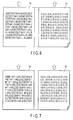
- FIG. 4 is a view showing a printing result in a first operation mode in each embodiment;
- FIG. 5 is a view showing a printing result in a second operation mode in each embodiment;
- FIG. 6 is a view showing a printing result in a third operation mode in each embodiment;
- FIG. 7 is a view showing a printing result in a fourth operation mode in each embodiment;
- FIG. 8 is a block diagram of a control circuit in a second embodiment;
- FIG. 9 is a view showing storage regions of a first and a second image memories in the second embodiment;
- FIG. 10 is a view showing a data reading direction from each image memory at the time of forward printing in the second embodiment;
- FIG. 11 is a time chart showing a data reading direction from each image memory at the time of forward printing in the second embodiment;
- FIG. 12 is a view showing a data reading direction from each image memory at the time of backward printing in the second embodiment; and
- FIG. 13 is a time chart showing a data reading direction from each image memory at the time of backward printing in the second embodiment.
- A first embodiment according to the present invention will now be described hereinafter with reference to the accompanying drawings. First, FIG. 1 shows a structure of a primary part.
-
Reference numeral 1 denotes a thermal paper sheet. Thethermal paper sheet 1 has heat-sensitive layers on both surfaces thereof, i.e., a first surface (which will be referred to as a front surface) 1a and a second surface (which will be referred to as a rear surface) 1b, respectively. Thethermal paper sheet 1 is rolled up in such a manner that thefront surface 1a becomes an inner side, and fed in a direction indicated by an arrow in the drawing by a later-describedpaper feed mechanism 22. The heat-sensitive layer is made up of a material that is colored into, e.g., black or red when heated to a predetermined temperature or above. - A first
thermal head 2 that comes into contact with thefront surface 1a of thethermal paper sheet 1 and a secondthermal head 4 that comes into contact with therear surface 1b of the same are provided along a paper feed direction of thisthermal paper sheet 1. The firstthermal head 2 has many heating elements arranged in a direction perpendicular to the paper feed direction of thethermal paper sheet 1, and prints an image corresponding to input data on thefront surface 1a of thethermal paper sheet 1. The secondthermal head 4 has many heating elements arranged in a direction perpendicular to the paper feed direction of thethermal paper sheet 1, and prints an image corresponding to input data on therear surface 1b of thethermal paper sheet 1. Thesethermal heads thermal paper sheet 1. The firstthermal head 2 is arranged on a downstream side of the secondthermal head 4 in the paper feed direction. - Further, a
first platen roller 3 is arranged at a position facing the firstthermal head 2, with thethermal paper sheet 1 being interposed therebetween, and asecond platen roller 5 is arranged at a position facing the secondthermal head 4, with thethermal paper sheet 1 being interposed therebetween. Furthermore, acutter 6 that cuts thethermal paper sheet 1 on a rear side of a printing region is arranged on a downstream side of the firstthermal head 2 in the paper feed direction. - FIG. 2 shows a control circuit of a thermal printer
main body 10 including the structure depicted in FIG. 1. - To a
CPU 11 as a control section are connected anROM 12 that stores a control program, anRAM 13 that storage data, acommunication interface 14 that performs data transmission/reception with respect to ahost device 30, anoperating section 15 that sets operating conditions, a paperfeed drive circuit 21 that drives apaper feed mechanism 16 for thethermal paper sheet 1, acutter drive circuit 22 that drives thecutter 6, afirst head controller 23 that drives and controls the firstthermal head 2 in accordance with later-described first printing data D1 asecond head controller 24 that drives and controls the secondthermal head 4 in accordance with later-described second printing data D2, and others. - As shown in FIG. 3, the first
thermal head 2 is constituted of alatch circuit 41, anenergization control circuit 42, and anedge head 43. Theedge head 43 has many heat-transfer heating elements latch circuit 41 latches data serially read from afirst image memory 25 in accordance with a strobe signal STB supplied from thehead controller 23. Theenergization control circuit 42 controls energization with respect to theheating elements edge head 43 in accordance with data in thelatch circuit 41 at a timing at which an enable signal ENB supplied from thehead drive circuit 23 becomes active. The secondthermal head 4 also has the same structure as that of the firstthermal head 2. - On the other hand, the
CPU 11 selectively controls forward printing and backward printing of the firstthermal head 2 with respect to thefront surface 1a of thethermal paper sheet 1, and also selectively controls forward printing and backward printing of the secondthermal head 4 with respect to therear surface 1b of thethermal paper sheet 1. TheCPU 11 has the following means (1) to (6) as primary functions. - (1) First controlling means for dividing printing data D0 input from the
external host device 30 into the first printing data D1 and the second printing data D2. The divided printing data D1 and D2 are stored in theRAM 13 together with the printing data D0. - (2) Second controlling means for serially reading the first printing data D1 in the
RAM 13 in a direction from a most significant bit to a least significant bit and inputting the read data to the firstthermal head 2 via thefirst head controller 23 at the time of forward printing with respect to thefront surface 1a of thethermal paper sheet 1. - (3) Third controlling means for serially reading the first printing data D1 in the
RAM 13 in a direction from the least significant bit to the most significant bit and inputting the read data to the firstthermal head 2 via thefirst head controller 23 at the time of backward printing with respect to thefront surface 1a of thethermal paper sheet 1. - (4) Fourth controlling means for serially reading the second printing data D2 in the
RAM 13 in the direction from the most significant bit to the least significant bit and inputting the read data to the secondthermal head 4 via thesecond head controller 24 at the time of forward printing with respect to therear surface 1b of thethermal paper sheet 1. - (5) Fifth controlling means for serially reading the second printing data D2 in the
RAM 13 in the direction from the least significant bit to the most significant bit and inputting the read data to the secondthermal head 4 via thesecond head controller 24 at the time of backward printing with respect to therear surface 1b of thethermal paper sheet 1. - (6) Sixth controlling means for first starting driving of the second
thermal head 4 while feeding thethermal paper sheet 1, and then starting driving of the firstthermal head 2 when a printing start position based on the first driving corresponds to the firstthermal head 2. - A function will now be explained.
- When the printing data D0 is input to the thermal printer
main body 10 from theexternal host device 30, the printing data D0 is stored in theRAM 13. In accordance with this storage, the printing data D0 is divided into the first printing data D1 and the second printing data D2 based on preset conditions. The divided first printing data D1 and second printing data D2 are stored in theRAM 13 together with the printing data D0. - After this division, feeding of the
thermal paper sheet 1 is started, and driving of the secondthermal head 4 is first commenced, thereby executing printing on therear surface 1b of thethermal paper sheet 1. When feeding of thethermal paper sheet 1 advances and a printing start position on therear surface 1b side based on driving of the secondthermal head 4 enters a state corresponding to the firstthermal head 2, driving of the firstthermal head 2 is started, thus executing printing on thefront surface 1a of thethermal paper sheet 1. - In this double-side printing, if a first operation mode is set by the operating
portion 15 or when the first operation mode is instructed from thehost device 30, the first printing data D1 in theRAM 13 is serially read in the direction from the most significant bit (MSB) to the least significant bit (LSB) to be input to the firstthermal head 2 via thefirst head controller 23. - Likewise, the second printing data D2 in the
RAM 13 is serially read in the direction from the most significant bit (MSB) to the least significant bit (LSB) to be input to the secondthermal head 4 via thesecond head controller 24. - In this manner, as shown in FIG. 4, an image corresponding to the first printing data D1 is printed on the
front surface 1a of thethermal paper sheet 1 in the forward direction. Furthermore, an image corresponding to the second printing data D2 is printed on therear surface 1b of thethermal paper sheet 1 in the forward direction. - The printed
thermal paper sheet 1 is cut by thecutter 6 to be provided as, e.g., a sales receipt to a customer. - If a second operation mode is set by the operating
portion 15 or when the second operation mode is instructed from thehost device 30, the first printing data D1 in atime chart 13 is serially read in the direction from the least significant bit (LSB) to the most significant bit (MSB) to be input to the firstthermal head 2 via thefirst head controller 23. - Moreover, the second printing data D2 in the
RAM 13 is serially read in the direction from the most significant bit (MSB) to the least significant bit (LSB) to be input to the secondthermal head 4 via thesecond head controller 24. - In this manner, as shown in FIG. 5, an image corresponding to the first printing data D1 is printed on the
front surface 1a of thethermal paper sheet 1 in the backward direction. Additionally, an image corresponding to the second printing data D2 is printed on therear surface 1b of thethermal paper sheet 1 in the forward direction. - If a third operation mode is set by the operating
portion 15 or when the third operation mode is instructed from thehost device 30, the first printing data D1 in theRAM 13 is serially read in the direction from the most significant bit (MSB) to the least significant bit (LSB) to be input to the firstthermal head 2 via thefirst head controller 23. - Further, the second printing data D2 in the
RAM 13 is serially read in the direction from the least significant bit (LSB) to the most significant bit (MSB) to be input to the secondthermal head 4 via thesecond head controller 24. - In this manner, as shown in FIG. 6, an image corresponding to the first printing data D1 is printed on the
front surface 1a of thethermal paper sheet 1 in the forward direction. Furthermore, an image corresponding to the second printing data D2 is printed on therear surface 1b of thethermal paper sheet 1 in the backward direction. - If a fourth operation mode is set by the operating
portion 15 or when the fourth operation mode is instructed from thehost device 30, the first printing data D1 in theRAM 13 is serially read in the direction from the least significant bit (LSB) to the most significant bit (MSB) to be input to the firstthermal head 2 via thefirst head controller 23. - Likewise, the second printing data D2 in the
RAM 13 is serially read in the direction from the least significant bit (LSB) to the most significant bit (MSB) to be input to the secondthermal head 4 via thesecond head controller 24. - In this manner, as shown in FIG. 7, an image corresponding to the first printing data D1 is printed on the
front surface 1a of thethermal paper sheet 1 in the backward direction. Moreover, an image corresponding to the second printing data D2 is printed on therear surface 1b of thethermal paper sheet 1 in the backward direction. - As explained above, the
thermal paper sheet 1 having the heat-sensitive layers on both surfaces thereof is prepared, and the firstthermal head 2 that comes into contact with thefront surface 1a of thethermal paper sheet 1 and the secondthermal head 4 that comes into contact with therear surface 1b of the same are provided. The printing data D0 input from thehost device 30 is divided into the first printing data D1 and the second printing data D2, and thethermal heads front surface 1a and therear surface 1b of thethermal paper sheet 1. - Therefore, even if an amount of the printing data D0 is large, a length of the
thermal paper sheet 1 on which data is to be printed can be reduced. When thethermal paper sheet 1 is used as, e.g., a sales receipt at a store, many pieces of commodity purchase data can be printed on the short receipt, and hence thethermal paper sheet 1 is easy to handle for users. This also saves thermal paper. - Additionally, since the reading directions of the first printing data D1 and the second printing data D2 can be appropriately switched, images corresponding to the printing data D1 and D2 can be printed on both surfaces of the
thermal paper sheet 1 in both the forward and the backward directions. Adopting the forward printing and the backward printing allows thethermal paper sheet 1 to be used in various applications. - When a conventional single-side printing type thermal printer is connected with the
host device 30, simply replacing the conventional thermal printer with the thermal printermain body 10 according to this embodiment easily allows the processing of dividing the printing data D0 and the double-side printing processing to be executed, without changing hardware and software on thehost device 30 side. Since only the thermal printer is replaced, the functions can be enhanced while suppressing an increase in a cost on a user side to the minimum level. - A second embodiment according to the present invention will now be described with reference to the accompanying drawings. The basic structure is the same as that depicted in FIG. 1, thereby omitting an explanation thereof. FIG. 8 shows a control circuit of a thermal printer
main body 10 including the structure depicted in FIG. 1. - To a
CPU 11 as a control section are connected to aROM 12 that stores a control program, aRAM 13 that stores data, acommunication interface 14 that performs data transmission/reception with respect to ahost device 30, an operatingportion 15 that sets operating conditions, a paperfeed drive circuit 21 that drives apaper feed mechanism 16 of athermal paper sheet 1, acutter drive circuit 22 that drives acutter 6, afirst head controller 23 that drives and controls a firstthermal head 2 in accordance with later-described first printing data D1, asecond head controller 24 that drives and controls a secondthermal head 4 in accordance with later-described second printing data D2, afirst image memory 25 that stores the later-described first printing data D1, asecond image memory 26 that stores the later-described second printing data D2, and others. - As shown in FIG. 9, the
first image memory 25 has 24 raster storage regions, each of which has 36 16-bit storage regions aligned in one raster. As shown in FIG. 10, addresses "0" to "863" are set in accordance with each 16-bit storage region. Thesecond image memory 26 has the same structure. - The structure of each of the first
thermal head 2 and the secondthermal head 4 is the same as that depicted in FIG. 3, thereby omitting an explanation thereof. - On the other hand, the
CPU 11 selectively controls forward printing and backward printing of the firstthermal head 2 with respect to afront surface 1a of thethermal paper sheet 1, and also selectively controls forward printing and backward printing of the secondthermal head 4 with respect to arear surface 1b of thethermal paper sheet 1. TheCPU 11 has the following means (11) to (16) as primary functions. - (11) First controlling means for dividing printing data D0 input from the
external host device 30 into the first printing data D1 and the second printing data D2, and storing the first printing data D1 in thefirst image memory 25 while storing the second printing data D2 in thesecond image memory 26. - (12) Second controlling means for serially reading the first printing data D1 in the
first image memory 25 in a direction from a most significant bit to a least significant bit in accordance with each raster and inputting the read data to the firstthermal head 2 via thefirst head controller 23 at the time of forward printing with respect to thefront surface 1a of thethermal paper sheet 1. - (13) A third controlling means for serially reading the first printing data D1 in the
first image memory 25 in a direction from the least significant bit to the most significant bit in accordance with each raster and inputting the read data to the firstthermal head 2 via thefirst head controller 23 at the time of backward printing with respect to thefront surface 1a of thethermal paper sheet 1. - (14) Fourth controlling means for serially reading the second printing data D2 in the
second image memory 26 in the direction from the most significant bit to the least significant bit in accordance with each raster and inputting the read data to the secondthermal head 4 via the second head controller at the time of forward printing with respect to therear surface 1b of thethermal paper sheet 1. - (15) Fifth controlling means for serially reading the second printing data D2 in the
second image memory 26 in the direction from the least significant bit to the most significant bit in accordance with each raster and inputting the read data to the secondthermal head 4 via thesecond head controller 24 at the time of backward printing with respect to therear surface 1b of thethermal paper sheet 1. - (16) Sixth controlling means for first starting driving of the second
thermal head 4 while feeding thethermal paper sheet 1, and then starting driving of the firstthermal head 2 when a printing start position based on first driving corresponds to the firstthermal head 2. - A function will now be explained.
- When the printing data D0 is input to the thermal printer
main body 10 from theexternal host device 30, the printing data D0 is stored in theRAM 13. In accordance with this storage, the printing data D0 is divided into the first printing data D1 and the second printing data D2 based on preset conditions. The divided first printing data D1 is stored in thefirst image memory 25, and the second printing data D2 is stored in thesecond image memory 26. - After the division, feeding of the
thermal paper sheet 1 is started, and driving of the secondthermal head 4 is first commenced, thereby executing printing on therear surface 1b of thethermal paper sheet 1. When feeding of thethermal paper sheet 1 advances and a printing start position on therear surface 1b side based on driving of the secondthermal head 4 enters a state corresponding to the firstthermal head 2, driving of the firstthermal head 2 is started, thus executing printing on thefront surface 1a of thethermal paper sheet 1. - In this double-side printing, if a first operation mode is set by the operating
portion 15 or when the first operation mode is instructed from thehost device 30, as shown in FIGS. 5 and 6, the first printing data D1 in thefirst image memory 25 is serially read in a direction of a most significant bit (MSB) "15" to a least significant bit (LSB) "0" and in a direction from a minimum address "0" to a maximum address "863" in accordance with each raster to be input to the firstthermal head 2 via thefirst head controller 23. - Likewise, the second printing data D2 in the
second image memory 26 is serially read in a direction from the most significant bit (MSB) "15" to the least significant bit (LSB) "0" and in a direction from the minimum address "0" to the maximum address "863" in accordance with each raster to be input to the secondthermal head 4 via thesecond head controller 24. - In this manner, as shown in FIG. 4, an image corresponding to the first printing data D1 is printed on the
front surface 1a of thethermal paper sheet 1 in the forward direction. Furthermore, an image corresponding to the second printing data D2 is printed on therear surface 1b of thethermal paper sheet 1 in the forward direction. - The printed
thermal paper sheet 1 is cut by acutter 6 to be provided as, e.g., a sales receipt to a customer. - If a second operation mode is set by the operating
portion 15 or when the second operation mode is instructed from thehost device 30, as shown in FIGS. 12 and 13, the first printing data D1 in thefirst image memory 25 is serially read in the direction from the least significant bit (LSB) "0" to the most significant bit (MSB) "15" and in the direction from the maximum address "863" to the minimum address "0" in accordance with each raster to be input to the firstthermal head 2 via thefirst head controller 23. - Moreover, as shown in FIGS. 10 and 11, the second printing data D2 in the
second image memory 26 is serially read in the direction from the most significant bit (MSB) "15" to the least significant bit (LSB) "0" and in the direction from the minimum address "0" to the maximum address "863" in accordance with each raster to be input to the secondthermal head 4 via thesecond head controller 24. - In this manner, as shown in FIG. 5, an image corresponding to the first printing data D1 is printed on the
front surface 1a of thethermal paper sheet 1 in the backward direction. An image corresponding to the second printing data D2 is printed on therear surface 1b of thethermal paper sheet 1 in the forward direction. - If a third operation mode is set by the operating
portion 15 or when the third operation mode is instructed from thehost device 30, as shown in FIGS. 10 and 11, the first printing data D1 in thefirst image memory 25 is serially read in the direction from the most significant bit (MSB) "15" to the least significant bit (LSB) "0" and in the direction from the minimum address "0" to the maximum address "863" in accordance with each raster to be input to the firstthermal head 2 via thefirst head controller 23. - Further, as shown in FIGS. 12 and 13, the second printing data D2 in the
second image memory 26 is serially read in the direction from the least significant bit (LSB) "0" to the most significant bit (MSB) "15" and in the direction from the maximum address "863" to the minimum address "0" in accordance with each raster to be input to the secondthermal head 4 via thesecond head controller 24. - In this manner, as shown in FIG. 6, an image corresponding to the first printing data D1 is printed on the
front surface 1a of thethermal paper sheet 1 in the forward direction. Furthermore, an image corresponding to the second printing data D2 is printed on therear surface 1b of thethermal paper sheet 1 in the backward direction. - If a fourth operation mode is set by the operating
portion 15 or when the fourth operation mode is instructed from thehost device 30, as shown in FIGS. 12 and 13, the first printing data D1 in thefirst image memory 25 is serially read in the direction from the least significant bit (LSB) "0" to the most significant bit (MSB) "15" and in the direction from the maximum address "863" to the minimum address "0" to be input to the firstthermal head 2 via thefirst head controller 23. - Likewise, as shown in FIGS. 12 and 13, the second printing data D2 in the
second image memory 26 is serially read in the direction from the least significant bit (LSB) "0" to the most significant bit (MSB) "15" and in the direction from the maximum address "863" to the minimum address "0" in accordance with each raster to be input to the secondthermal head 4 via thesecond head controller 24. - In this manner, as shown in FIG. 7, an image corresponding to the first printing data D1 is printed on the
front surface 1a of thethermal paper sheet 1 in the backward direction. Furthermore, an image corresponding to the second printing data D2 is printed on therear surface 1b of thethermal paper sheet 1 in the backward direction. - As explained above, the
thermal paper sheet 1 having the heat-sensitive layers on both surfaces thereof is prepared, and the firstthermal head 2 that comes into contact with thefront surface 1a of thethermal paper sheet 1 and the secondthermal head 4 that comes into contact with therear surface 1b of the same are provided. The printing data D0 input from thehost device 30 is divided into the first printing data D1 and the second printing data D2, and thethermal heads front surface 1a and therear surface 1b of thethermal paper sheet 1. - Therefore, even if an amount of the printing data D0 is large, a length of the
thermal paper sheet 1 on which data is to be printed can be reduced. When thethermal paper sheet 1 is used as, e.g., a sales receipt at a store, many pieces of commodity purchase data can be printed on the short receipt, and hence thethermal paper sheet 1 is easy to handle for users. This also saves thermal paper. - Moreover, the first printing data D1 and the second printing data D2 are stored in the
first image memory 25 and thesecond image memory 26, and the reading directions of the stored printing data D1 and D2 can be appropriately switched. As a result, images corresponding to the printing data D1 and D2 can be printed on both surfaces of thethermal paper sheet 1 in both the forward direction and the backward direction. Adopting the forward printing and the backward printing allows thethermal paper sheet 1 to be used in various applications. - When a single-side printing type thermal printer is connected with the
host device 30, simply replacing this thermal printer with the thermal printermain body 10 according to this embodiment easily allows the processing of dividing the printing data D0 and the double-side printing processing to be executed without changing hardware and software on thehost device 30 side. Since only the thermal printer is replaced, the functions can be enhanced while suppressing an increase in a cost on a user side to the minimum level. - Further, the embodiments are not limited to a thermal printer using the
thermal paper sheet 1 having the front surface and the rear surface on which the heat-sensitive layer is formed respectively. The embodiments of the present invention can also be applied to a thermal printer adopting a mechanism for feeding an ink ribbon between thethermal heads
Claims (14)
- A thermal printer, characterized by comprising:a thermal paper sheet (1) which has heat-sensitive layers on both surfaces (1a, 1b) thereof, and is subjected to paper feeding;a first thermal head (2) which comes into contact with a first surface (1a) of the thermal paper sheet (1) ;a second thermal head (4) which comes into contact with a second surface (1b) of the thermal paper sheet (1); anda control section (11) which selectively controls forward printing and backward printing of the first thermal head (2) with respect to the first surface (1a) of the thermal paper sheet (1) and also selectively controls forward printing and backward printing of the second thermal head (4) with respect to the second surface (1b) of the thermal paper sheet (1).
- The thermal printer according to claim 1, characterized in that each of the thermal heads (2, 4) has a plurality of heating elements (43a, 43b, ··· 43n) that are linearly arranged along a direction perpendicular to a paper feed direction of the thermal paper sheet (1).
- The thermal printer according to claim 1, characterized in that the first thermal head (2) and the second thermal head (4) are provided at positions separated from each other along the paper feed direction of the thermal paper sheet (1).
- The thermal printer according to claim 3, characterized in that the first thermal head (2) is present on a downstream side of the second thermal head (4) in the paper feed direction.
- The thermal printer according to claim 1, characterized in that the first thermal head (2) prints an image corresponding to input printing data on the first surface (1a) of the thermal paper sheet (1),
the second thermal head prints an image corresponding to input printing data on the second surface (1b) of the thermal paper sheet (1), and
the control section (11) has:first controlling means for dividing printing data (D0) formed of a plurality of bits input from the outside into first printing data (D1) and second printing data (D2);second controlling means for serially reading the first printing data (D1) in a direction from a most significant bit to a least significant bit and inputting the read data to the first thermal head (2) at the time of forward printing with respect to the first surface (1a) of the thermal paper sheet (1);third controlling means for serially reading the first printing data (D1) in a direction from the least significant bit to the most significant bit and inputting the read data to the first thermal head (2) at the time of backward printing with respect to the first surface (1a) of the thermal paper sheet (1);fourth controlling means for serially reading the second printing data (D2) in the direction from the most significant bit to the least significant bit and inputting the read data to the second thermal head (4) at the time of forward printing with respect to the second surface (1b) of the thermal paper sheet (1); andfifth controlling means for serially reading the second printing data (D2) in the direction from the least significant bit to the most significant bit and inputting the read data to the second thermal head (4) at the time of backward printing with respect to the second surface (1b) of the thermal paper sheet (1). - The thermal printer according to claim 4, characterized in that the first thermal head (2) prints an image corresponding to input printing data on the first surface (1a) of the thermal paper sheet (1),
the second thermal head prints an image corresponding to input printing data on the second surface (1b) of the thermal paper sheet (1), and
the control section (11) has:first controlling means for dividing printing data (D0) formed of a plurality of bits input from the outside into first printing data (D1) and second printing data (D2);second controlling means for serially reading the first printing data (D1) in a direction from a most significant bit to a least significant bit and inputting the read data to the first thermal head (2) at the time of forward printing with respect to the first surface (1a) of the thermal paper sheet (1);third controlling means for serially reading the first printing data (D1) in a direction from the least significant bit to the most significant bit and inputting the read data to the first thermal head (2) at the time of backward printing with respect to the first surface (1a) of the thermal paper sheet (1);fourth controlling means for serially reading the second printing data (D2) in the direction from the most significant bit to the least significant bit and inputting the read data to the second thermal head (4) at the time of forward printing with respect to the second surface (1b) of the thermal paper sheet (1);fifth controlling means for serially reading the second printing data (D2) in the direction from the least significant bit to the most significant bit and inputting the read data to the second thermal head (4) at the time of backward printing with respect to the second surface (1b) of the thermal paper sheet (1); andsixth controlling means for first starting driving of the second thermal head (4) while feeding the thermal paper sheet (1), and starting driving of the first thermal head (2) when a printing start position based on the first driving corresponds to the first thermal head (2). - The thermal printer according to claim 1, characterized by further comprising:a first image memory (25) and a second image memory (26).
- The thermal printer according to claim 7, characterized in that the first thermal head (2) prints an image corresponding to input printing data on the first surface (1a) of the thermal paper sheet (1),
the second thermal head (4) prints an image corresponding to input printing data on the second surface (1b) of the thermal paper sheet (1), and
the control section (11) has:first controlling means for dividing printing data (D0) formed of a plurality of bits input from the outside into first printing data (D1) and second printing data (D2), storing the first printing data (D1) in the first image memory (25), and storing the second printing data (D2) in the second image memory (26);second controlling means for serially reading the first printing data (D1) in the first image memory (25) in a direction from a most significant bit to a least significant bit and inputting the read data to the first thermal head (2) at the time of forward printing with respect to the first surface (1a) of the thermal paper sheet (1);third controlling means for serially reading the first printing data (D1) in the first image memory (25) in a direction from the least significant bit to the most significant bit and inputting the read data to the first thermal head (2) at the time of backward printing with respect to the first surface (1a) of the thermal paper sheet (1);fourth controlling means for serially reading the second printing data (D2) in the second image memory (26) in the direction from the most significant bit to the least significant bit and inputting the read data to the second thermal head (4) at the time of forward printing with respect to the second surface (1b) of the thermal paper sheet (1); andfifth controlling means for serially reading the second printing data (D2) in the second image memory (26) in the direction from the least significant bit to the most significant bit and inputting the read data to the second thermal head (4) at the time of backward printing with respect to the second surface (1b) of the thermal paper sheet (1). - The thermal printer according to claim 7, characterized in that the first thermal head (2) has latching means to which printing data (D0) formed of a plurality of bits corresponding to one raster is serially input, and prints an image corresponding to the data in the latching means on the first surface (1a) of the thermal paper sheet (1),
the second thermal head (4) has latching means to which printing data (D0) formed of a plurality of bits corresponding to one raster is serially input, and prints an image corresponding to the data in the latching means on the second surface (1b) of the thermal paper sheet (1), and
the control section (11) has:first controlling means for dividing printing data formed (D0) of a plurality of bits input from the outside into first printing data (D1) and second printing data (D2), storing the first printing data (D1) in the first image memory (25), and storing the second printing data in the second image memory (26);second controlling means for serially reading the first printing data (D1) in the first image memory (25) in a direction from a most significant bit to a least significant bit in accordance with each raster and inputting the read data to the first thermal head (2) at the time of forward printing with respect to the first surface (1a) of the thermal paper sheet (1);third controlling means for serially reading the first printing data (D1) in the first image memory (25) in a direction from the least significant bit to the most significant bit in accordance with each raster and inputting the read data to the first thermal head (2) at the time of backward printing with respect to the first surface (1a) of the thermal paper sheet (1);fourth controlling means for serially reading the second printing data (D2) in the second image memory (26) in the direction from the most significant bit to the least significant bit in accordance with each raster and inputting the read data to the second thermal head (4) at the time of forward printing with respect to the second surface (1b) of the thermal paper sheet (1); andfifth controlling means for serially reading the second printing data (D2) in the second image memory (26) in the direction from the least significant bit to the most significant bit in accordance with each raster and inputting the read data to the second thermal head (4) at the time of backward printing with respect to the second surface (1b) of the thermal paper sheet (1). - The thermal printer according to claim 4, characterized by further comprising:a first image memory (25) and a second image memory (26).
- The thermal printer according to claim 10, characterized in that the first thermal head (2) prints an image corresponding to input printing data on the first surface (1a) of the thermal paper sheet (1),
the second thermal head (4) prints an image corresponding to input printing data on the second surface (1b) of the thermal paper sheet (1), and
the control section (11) has:first controlling means for dividing printing data (D0) formed of a plurality of bits input from the outside into first printing data (D1) and second printing data (D2), storing the first printing data (D1) in the first image memory (25), and storing the second printing data (D2) in the second image memory (26);second controlling means for serially reading the first printing data (D1) in the first image memory (25) in a direction from a most significant bit to a least significant bit and inputting the read data to the first thermal head (2) at the time of forward printing with respect to the first surface (1a) of the thermal paper sheet (1);third controlling means for serially reading the first printing data (D1) in the first image memory (25) in a direction from the least significant bit to the most significant bit and inputting the read data to the first thermal head (2) at the time of backward printing with respect to the first surface (1a) of the thermal paper sheet (1);fourth controlling means for serially reading the second printing data (D2) in the second image memory in the direction from the most significant bit to the least significant bit and inputting the read data to the second thermal head (4) at the time of forward printing with respect to the second surface (1b) of the thermal paper sheet (1);fifth controlling means for serially reading the second printing data (D2) in the second image memory (26) in the direction from the least significant bit to the most significant bit and inputting the read data to the second thermal head (4) at the time of backward printing with respect to the second surface (1b) of the thermal paper sheet (1); andsixth controlling means for first starting driving of the second thermal head (4) while feeding the thermal paper sheet (1), and starting driving of the first thermal head (2) when a printing start position based on the first driving corresponds to the first thermal head (2). - The thermal printer according to claim 10, characterized in that the first thermal head (2) has latching means to which printing data (D0) formed of a plurality of bits corresponding to one raster is serially input, and prints an image corresponding to the data in the latching means on the first surface (1a) of the thermal paper sheet (1),
the second thermal head (4) has latching means to which printing data (D0) formed of a plurality of bits corresponding to one raster is serially input, and prints an image corresponding to the data in the latching means on the second surface (1b) of the thermal paper sheet (1), and
the control section (11) has:first controlling means for dividing printing data (D0) formed of a plurality of bits input from the outside into first printing data (D1) and second printing data (D2), storing the first printing data (D1) in the first image memory (25), and storing the second printing data (D2) in the second image memory (26);second controlling means for serially reading the first printing data (D1) in the first image memory (25) in a direction from a most significant bit to a least significant bit in accordance with each raster and inputting the read data to the first thermal head (2) at the time of forward printing with respect to the first surface (1a) of the thermal paper sheet (1);third controlling means for serially reading the first printing data in the first image memory (25) in a direction from the least significant bit to the most significant bit in accordance with each raster and inputting the read data to the first thermal head (2) at the time of backward printing with respect to the first surface (1a) of the thermal paper sheet (1);fourth controlling means for serially reading the second printing data (D2) in the second image memory (26) in a direction from the most significant bit to the least significant bit in accordance with each raster and inputting the read data to the second thermal head (4) at the time of forward printing with respect to the second surface (1b) of the thermal paper sheet (1);fifth controlling means for serially reading the second printing data in the second image memory (26) in the direction from the least significant bit to the most significant bit in accordance with each raster and inputting the read data to the second thermal head (4) at the time of backward printing with respect to the second surface (1b) of the thermal paper sheet (1); andsixth controlling means for first starting driving of the second thermal head (4) while feeding the thermal paper sheet (1), and starting driving of the first thermal head (2) when a printing start position based on the first driving corresponds to the first thermal head (2). - A method of controlling a thermal printer characterized by comprising: a thermal paper sheet (1) which has heat-sensitive layers on both surfaces (1a, 1b) thereof, and is subjected to paper feeding; a first thermal head (2) which comes into contact with a first surface (1a) of the thermal paper sheet (1); and a second thermal head (4) which comes into contact with a second surface (1b) of the thermal paper sheet (1), the method comprising:selectively controlling forward printing and backward printing of the first thermal head (2) with respect to the first surface (1a) of the thermal paper sheet (1); andselectively controlling forward printing and backward printing of the second thermal head (4) with respect to the second surface (1b) of the thermal paper sheet (1).
- A method of controlling a thermal printer characterized by comprising: a thermal paper sheet (1) which has heat-sensitive layers on both surfaces (1a, 1b) thereof, and is subjected to paper feeding; a first thermal head (2) which prints an image corresponding to input printing data on a first surface (1a) of the thermal paper sheet (1); and a second thermal head (4) which prints an image corresponding to input printing data on a second surface (1b) of the thermal paper sheet (1), the method comprising:dividing printing data (D0) formed of a plurality of bits input from the outside into first printing data (D1) and second printing data (D2);serially reading the first printing data (D1) in a direction from a most significant bit to a least significant bit and inputting the read data to the first thermal head (2) at the time of forward printing with respect to the first surface (1a) of the thermal paper sheet (1);serially reading the first printing data (D1) in a direction from the least significant bit to the most significant bit and inputting the read data to the first thermal head (2) at the time of backward printing with respect to the first surface (1a) of the thermal paper sheet (1);serially reading the second printing data (D2) in the direction from the most significant bit to the least significant bit and inputting the read data to the second thermal head (4) at the time of forward printing with respect to the second surface (1b) of the thermal paper sheet (1); andserially reading the second printing data (D2) in the direction from the least significant bit to the most significant bit and inputting the read data to the second thermal head (4) at the time of backward printing with respect to the second surface (1b) of the thermal paper sheet (1).
Applications Claiming Priority (2)
| Application Number | Priority Date | Filing Date | Title |
|---|---|---|---|
| JP2006151694A JP2007320122A (en) | 2006-05-31 | 2006-05-31 | Thermal printer and control method thereof |
| JP2006152576A JP2007320161A (en) | 2006-05-31 | 2006-05-31 | Thermal printer and control method thereof |
Publications (2)
| Publication Number | Publication Date |
|---|---|
| EP1862321A1 true EP1862321A1 (en) | 2007-12-05 |
| EP1862321B1 EP1862321B1 (en) | 2010-03-03 |
Family
ID=38515533
Family Applications (1)
| Application Number | Title | Priority Date | Filing Date |
|---|---|---|---|
| EP07109061A Active EP1862321B1 (en) | 2006-05-31 | 2007-05-29 | Thermal printer and method of controlling the same |
Country Status (3)
| Country | Link |
|---|---|
| US (1) | US7679632B2 (en) |
| EP (1) | EP1862321B1 (en) |
| DE (1) | DE602007005046D1 (en) |
Families Citing this family (4)
| Publication number | Priority date | Publication date | Assignee | Title |
|---|---|---|---|---|
| US7524824B2 (en) * | 2003-09-04 | 2009-04-28 | Pacific Arrow Limited | Composition comprising Xanthoceras sorbifolia extracts, compounds isolated from same, methods for preparing same and uses thereof |
| US7488753B2 (en) * | 2003-10-09 | 2009-02-10 | Pacific Arrow Limited | Composition comprising triterpene saponins and compounds with angeloyl functional group, methods for preparing same and uses thereof |
| JP2010064271A (en) * | 2008-09-08 | 2010-03-25 | Toshiba Tec Corp | Thermal printer and control method thereof |
| WO2016014481A1 (en) * | 2014-07-22 | 2016-01-28 | The Coca-Cola Company | Systems and methods for monitoring overprint orientation |
Citations (3)
| Publication number | Priority date | Publication date | Assignee | Title |
|---|---|---|---|---|
| JPH0624082A (en) | 1991-10-03 | 1994-02-01 | Ricoh Co Ltd | Double-sided printing device |
| JPH09233256A (en) | 1996-02-23 | 1997-09-05 | Ricoh Co Ltd | Facsimile machine |
| EP1321296A2 (en) * | 2001-12-18 | 2003-06-25 | Ncr International Inc. | Direct thermal printer |
Family Cites Families (16)
| Publication number | Priority date | Publication date | Assignee | Title |
|---|---|---|---|---|
| JPS5793486A (en) | 1980-12-02 | 1982-06-10 | Fujitsu Ltd | Printing device |
| JPS588668A (en) | 1981-07-08 | 1983-01-18 | Shinko Electric Co Ltd | Double side printing by heat sensitive printer |
| JPS613765A (en) | 1984-06-18 | 1986-01-09 | Konishiroku Photo Ind Co Ltd | Thermal transfer printer |
| JPS63137847A (en) | 1986-11-29 | 1988-06-09 | Mita Ind Co Ltd | Image generator for double-sided printing |
| JPH0351149A (en) | 1989-07-20 | 1991-03-05 | Fujitsu General Ltd | thermal transfer printer |
| JPH0627153A (en) | 1992-07-10 | 1994-02-04 | Furukawa Electric Co Ltd:The | Vertical modulation type optical voltage sensor |
| US6118469A (en) * | 1995-11-21 | 2000-09-12 | Seiko Epson Corporation | Thermal printer |
| JPH09289561A (en) | 1996-04-23 | 1997-11-04 | Ricoh Co Ltd | Facsimile apparatus and control method thereof |
| JPH1076713A (en) | 1996-09-03 | 1998-03-24 | Sony Corp | Double-sided simultaneous printing printer |
| JPH11286147A (en) | 1998-04-02 | 1999-10-19 | Nec Yonezawa Ltd | Double-sided printing mechanism |
| JP2000315275A (en) | 1999-05-06 | 2000-11-14 | Hitachi Ltd | Apparatus equipped with statement slip issuing mechanism |
| JP2001199095A (en) | 2000-01-18 | 2001-07-24 | Alps Electric Co Ltd | Duplex printer |
| US6759366B2 (en) * | 2001-12-18 | 2004-07-06 | Ncr Corporation | Dual-sided imaging element |
| JP2003200641A (en) | 2001-12-28 | 2003-07-15 | Hitachi Information Technology Co Ltd | Printing equipment |
| JP2005329572A (en) | 2004-05-18 | 2005-12-02 | Nidec Copal Corp | Thermal transfer printer |
| US7710442B2 (en) * | 2006-03-07 | 2010-05-04 | Ncr Corporation | Two-sided thermal print configurations |
-
2007
- 2007-03-05 US US11/681,925 patent/US7679632B2/en active Active
- 2007-05-29 EP EP07109061A patent/EP1862321B1/en active Active
- 2007-05-29 DE DE602007005046T patent/DE602007005046D1/en active Active
Patent Citations (3)
| Publication number | Priority date | Publication date | Assignee | Title |
|---|---|---|---|---|
| JPH0624082A (en) | 1991-10-03 | 1994-02-01 | Ricoh Co Ltd | Double-sided printing device |
| JPH09233256A (en) | 1996-02-23 | 1997-09-05 | Ricoh Co Ltd | Facsimile machine |
| EP1321296A2 (en) * | 2001-12-18 | 2003-06-25 | Ncr International Inc. | Direct thermal printer |
Also Published As
| Publication number | Publication date |
|---|---|
| US7679632B2 (en) | 2010-03-16 |
| DE602007005046D1 (en) | 2010-04-15 |
| EP1862321B1 (en) | 2010-03-03 |
| US20070279477A1 (en) | 2007-12-06 |
Similar Documents
| Publication | Publication Date | Title |
|---|---|---|
| EP1862323B1 (en) | Duplex printer | |
| US7782349B2 (en) | Thermal printer and method of controlling the same | |
| JP5279091B2 (en) | Double-sided direct thermal printer | |
| CN101081575B (en) | Thermal printer and method of controlling the same | |
| EP1862321B1 (en) | Thermal printer and method of controlling the same | |
| JPH0789115A (en) | Thermal printer | |
| JP4537977B2 (en) | Thermal printer and printing method therefor | |
| JP2014008771A (en) | Thermal printer and program therefor | |
| US20050041087A1 (en) | Photoprinter printing image on recording paper | |
| JP2002283648A (en) | Printing control apparatus and method, thermal transfer recording medium | |
| JP2007320188A (en) | Thermal printer and control method thereof | |
| JP2007320161A (en) | Thermal printer and control method thereof | |
| JP4201953B2 (en) | Serial printer | |
| JP4303261B2 (en) | Thermal printer and printing method therefor | |
| JP2007320122A (en) | Thermal printer and control method thereof | |
| US20250360726A1 (en) | Printer and method | |
| JP4299318B2 (en) | Thermal printer and control method thereof | |
| US8137015B2 (en) | Image forming method for determining a position of an ink ribbon with a boundary line | |
| JP2025171091A (en) | Control device, recording device, method, and program | |
| JP2541922B2 (en) | Thermal printer | |
| JP4568250B2 (en) | Character attribute management system for double-sided printing apparatus and character attribute management method thereof | |
| JPH07251533A (en) | Tape printer | |
| JPH06199003A (en) | Tape printing machine | |
| JP2013059924A (en) | Double-sided printing apparatus | |
| JPH11268355A (en) | Line printer |
Legal Events
| Date | Code | Title | Description |
|---|---|---|---|
| PUAI | Public reference made under article 153(3) epc to a published international application that has entered the european phase |
Free format text: ORIGINAL CODE: 0009012 |
|
| 17P | Request for examination filed |
Effective date: 20070529 |
|
| AK | Designated contracting states |
Kind code of ref document: A1 Designated state(s): AT BE BG CH CY CZ DE DK EE ES FI FR GB GR HU IE IS IT LI LT LU LV MC MT NL PL PT RO SE SI SK TR |
|
| AX | Request for extension of the european patent |
Extension state: AL BA HR MK YU |
|
| AKX | Designation fees paid |
Designated state(s): DE FR GB |
|
| RAP1 | Party data changed (applicant data changed or rights of an application transferred) |
Owner name: TOSHIBA TEC KABUSHIKI KAISHA Owner name: NCR CORPORATION |
|
| GRAP | Despatch of communication of intention to grant a patent |
Free format text: ORIGINAL CODE: EPIDOSNIGR1 |
|
| GRAS | Grant fee paid |
Free format text: ORIGINAL CODE: EPIDOSNIGR3 |
|
| GRAA | (expected) grant |
Free format text: ORIGINAL CODE: 0009210 |
|
| AK | Designated contracting states |
Kind code of ref document: B1 Designated state(s): DE FR GB |
|
| REG | Reference to a national code |
Ref country code: GB Ref legal event code: FG4D |
|
| REF | Corresponds to: |
Ref document number: 602007005046 Country of ref document: DE Date of ref document: 20100415 Kind code of ref document: P |
|
| PLBE | No opposition filed within time limit |
Free format text: ORIGINAL CODE: 0009261 |
|
| STAA | Information on the status of an ep patent application or granted ep patent |
Free format text: STATUS: NO OPPOSITION FILED WITHIN TIME LIMIT |
|
| 26N | No opposition filed |
Effective date: 20101206 |
|
| REG | Reference to a national code |
Ref country code: FR Ref legal event code: PLFP Year of fee payment: 10 |
|
| REG | Reference to a national code |
Ref country code: FR Ref legal event code: PLFP Year of fee payment: 11 |
|
| REG | Reference to a national code |
Ref country code: FR Ref legal event code: PLFP Year of fee payment: 12 |
|
| REG | Reference to a national code |
Ref country code: FR Ref legal event code: PLFP Year of fee payment: 17 |
|
| PGFP | Annual fee paid to national office [announced via postgrant information from national office to epo] |
Ref country code: DE Payment date: 20250402 Year of fee payment: 19 |
|
| PGFP | Annual fee paid to national office [announced via postgrant information from national office to epo] |
Ref country code: GB Payment date: 20250401 Year of fee payment: 19 |
|
| PGFP | Annual fee paid to national office [announced via postgrant information from national office to epo] |
Ref country code: FR Payment date: 20250401 Year of fee payment: 19 |