EP1862151B1 - Method for selection of an femoral implant - Google Patents
Method for selection of an femoral implant Download PDFInfo
- Publication number
- EP1862151B1 EP1862151B1 EP06011218A EP06011218A EP1862151B1 EP 1862151 B1 EP1862151 B1 EP 1862151B1 EP 06011218 A EP06011218 A EP 06011218A EP 06011218 A EP06011218 A EP 06011218A EP 1862151 B1 EP1862151 B1 EP 1862151B1
- Authority
- EP
- European Patent Office
- Prior art keywords
- femoral
- model
- implant
- value
- femoral implant
- Prior art date
- Legal status (The legal status is an assumption and is not a legal conclusion. Google has not performed a legal analysis and makes no representation as to the accuracy of the status listed.)
- Expired - Fee Related
Links
- GDOPTJXRTPNYNR-UHFFFAOYSA-N CC1CCCC1 Chemical compound CC1CCCC1 GDOPTJXRTPNYNR-UHFFFAOYSA-N 0.000 description 1
Images

Classifications
-
- A—HUMAN NECESSITIES
- A61—MEDICAL OR VETERINARY SCIENCE; HYGIENE
- A61F—FILTERS IMPLANTABLE INTO BLOOD VESSELS; PROSTHESES; DEVICES PROVIDING PATENCY TO, OR PREVENTING COLLAPSING OF, TUBULAR STRUCTURES OF THE BODY, e.g. STENTS; ORTHOPAEDIC, NURSING OR CONTRACEPTIVE DEVICES; FOMENTATION; TREATMENT OR PROTECTION OF EYES OR EARS; BANDAGES, DRESSINGS OR ABSORBENT PADS; FIRST-AID KITS
- A61F2/00—Filters implantable into blood vessels; Prostheses, i.e. artificial substitutes or replacements for parts of the body; Appliances for connecting them with the body; Devices providing patency to, or preventing collapsing of, tubular structures of the body, e.g. stents
- A61F2/02—Prostheses implantable into the body
- A61F2/30—Joints
- A61F2/46—Special tools or methods for implanting or extracting artificial joints, accessories, bone grafts or substitutes, or particular adaptations therefor
- A61F2/4657—Measuring instruments used for implanting artificial joints
-
- A—HUMAN NECESSITIES
- A61—MEDICAL OR VETERINARY SCIENCE; HYGIENE
- A61B—DIAGNOSIS; SURGERY; IDENTIFICATION
- A61B34/00—Computer-aided surgery; Manipulators or robots specially adapted for use in surgery
- A61B34/20—Surgical navigation systems; Devices for tracking or guiding surgical instruments, e.g. for frameless stereotaxis
-
- A—HUMAN NECESSITIES
- A61—MEDICAL OR VETERINARY SCIENCE; HYGIENE
- A61B—DIAGNOSIS; SURGERY; IDENTIFICATION
- A61B90/00—Instruments, implements or accessories specially adapted for surgery or diagnosis and not covered by any of the groups A61B1/00 - A61B50/00, e.g. for luxation treatment or for protecting wound edges
- A61B90/36—Image-producing devices or illumination devices not otherwise provided for
-
- A—HUMAN NECESSITIES
- A61—MEDICAL OR VETERINARY SCIENCE; HYGIENE
- A61B—DIAGNOSIS; SURGERY; IDENTIFICATION
- A61B17/00—Surgical instruments, devices or methods, e.g. tourniquets
- A61B2017/00681—Aspects not otherwise provided for
- A61B2017/00707—Dummies, phantoms; Devices simulating patient or parts of patient
- A61B2017/00712—Dummies, phantoms; Devices simulating patient or parts of patient simulating mathematical properties, e.g. for testing of positioning in the isocentre or focus
-
- A—HUMAN NECESSITIES
- A61—MEDICAL OR VETERINARY SCIENCE; HYGIENE
- A61B—DIAGNOSIS; SURGERY; IDENTIFICATION
- A61B34/00—Computer-aided surgery; Manipulators or robots specially adapted for use in surgery
- A61B34/10—Computer-aided planning, simulation or modelling of surgical operations
- A61B2034/101—Computer-aided simulation of surgical operations
- A61B2034/102—Modelling of surgical devices, implants or prosthesis
- A61B2034/104—Modelling the effect of the tool, e.g. the effect of an implanted prosthesis or for predicting the effect of ablation or burring
-
- A—HUMAN NECESSITIES
- A61—MEDICAL OR VETERINARY SCIENCE; HYGIENE
- A61B—DIAGNOSIS; SURGERY; IDENTIFICATION
- A61B34/00—Computer-aided surgery; Manipulators or robots specially adapted for use in surgery
- A61B34/10—Computer-aided planning, simulation or modelling of surgical operations
- A61B2034/101—Computer-aided simulation of surgical operations
- A61B2034/105—Modelling of the patient, e.g. for ligaments or bones
-
- A—HUMAN NECESSITIES
- A61—MEDICAL OR VETERINARY SCIENCE; HYGIENE
- A61B—DIAGNOSIS; SURGERY; IDENTIFICATION
- A61B34/00—Computer-aided surgery; Manipulators or robots specially adapted for use in surgery
- A61B34/10—Computer-aided planning, simulation or modelling of surgical operations
- A61B2034/108—Computer aided selection or customisation of medical implants or cutting guides
-
- A—HUMAN NECESSITIES
- A61—MEDICAL OR VETERINARY SCIENCE; HYGIENE
- A61B—DIAGNOSIS; SURGERY; IDENTIFICATION
- A61B34/00—Computer-aided surgery; Manipulators or robots specially adapted for use in surgery
- A61B34/20—Surgical navigation systems; Devices for tracking or guiding surgical instruments, e.g. for frameless stereotaxis
- A61B2034/2046—Tracking techniques
- A61B2034/2055—Optical tracking systems
-
- A—HUMAN NECESSITIES
- A61—MEDICAL OR VETERINARY SCIENCE; HYGIENE
- A61B—DIAGNOSIS; SURGERY; IDENTIFICATION
- A61B34/00—Computer-aided surgery; Manipulators or robots specially adapted for use in surgery
- A61B34/20—Surgical navigation systems; Devices for tracking or guiding surgical instruments, e.g. for frameless stereotaxis
- A61B2034/2068—Surgical navigation systems; Devices for tracking or guiding surgical instruments, e.g. for frameless stereotaxis using pointers, e.g. pointers having reference marks for determining coordinates of body points
-
- A—HUMAN NECESSITIES
- A61—MEDICAL OR VETERINARY SCIENCE; HYGIENE
- A61B—DIAGNOSIS; SURGERY; IDENTIFICATION
- A61B34/00—Computer-aided surgery; Manipulators or robots specially adapted for use in surgery
- A61B34/10—Computer-aided planning, simulation or modelling of surgical operations
-
- A—HUMAN NECESSITIES
- A61—MEDICAL OR VETERINARY SCIENCE; HYGIENE
- A61F—FILTERS IMPLANTABLE INTO BLOOD VESSELS; PROSTHESES; DEVICES PROVIDING PATENCY TO, OR PREVENTING COLLAPSING OF, TUBULAR STRUCTURES OF THE BODY, e.g. STENTS; ORTHOPAEDIC, NURSING OR CONTRACEPTIVE DEVICES; FOMENTATION; TREATMENT OR PROTECTION OF EYES OR EARS; BANDAGES, DRESSINGS OR ABSORBENT PADS; FIRST-AID KITS
- A61F2/00—Filters implantable into blood vessels; Prostheses, i.e. artificial substitutes or replacements for parts of the body; Appliances for connecting them with the body; Devices providing patency to, or preventing collapsing of, tubular structures of the body, e.g. stents
- A61F2/02—Prostheses implantable into the body
- A61F2/30—Joints
- A61F2/32—Joints for the hip
- A61F2/36—Femoral heads ; Femoral endoprostheses
- A61F2/3601—Femoral heads ; Femoral endoprostheses for replacing only the epiphyseal or metaphyseal parts of the femur, e.g. endoprosthetic femoral heads or necks directly fixed to the natural femur by internal fixation devices
- A61F2/3603—Femoral heads ; Femoral endoprostheses for replacing only the epiphyseal or metaphyseal parts of the femur, e.g. endoprosthetic femoral heads or necks directly fixed to the natural femur by internal fixation devices implanted without ablation of the whole natural femoral head
-
- A—HUMAN NECESSITIES
- A61—MEDICAL OR VETERINARY SCIENCE; HYGIENE
- A61F—FILTERS IMPLANTABLE INTO BLOOD VESSELS; PROSTHESES; DEVICES PROVIDING PATENCY TO, OR PREVENTING COLLAPSING OF, TUBULAR STRUCTURES OF THE BODY, e.g. STENTS; ORTHOPAEDIC, NURSING OR CONTRACEPTIVE DEVICES; FOMENTATION; TREATMENT OR PROTECTION OF EYES OR EARS; BANDAGES, DRESSINGS OR ABSORBENT PADS; FIRST-AID KITS
- A61F2/00—Filters implantable into blood vessels; Prostheses, i.e. artificial substitutes or replacements for parts of the body; Appliances for connecting them with the body; Devices providing patency to, or preventing collapsing of, tubular structures of the body, e.g. stents
- A61F2/02—Prostheses implantable into the body
- A61F2/30—Joints
- A61F2/46—Special tools or methods for implanting or extracting artificial joints, accessories, bone grafts or substitutes, or particular adaptations therefor
- A61F2002/4632—Special tools or methods for implanting or extracting artificial joints, accessories, bone grafts or substitutes, or particular adaptations therefor using computer-controlled surgery, e.g. robotic surgery
- A61F2002/4633—Special tools or methods for implanting or extracting artificial joints, accessories, bone grafts or substitutes, or particular adaptations therefor using computer-controlled surgery, e.g. robotic surgery for selection of endoprosthetic joints or for pre-operative planning
Definitions
- the present invention relates to a method and a device for selecting a femoral implant, which is preferably cemented to a femoral head in hip joint surgery, wherein by means of the inventive method and apparatus according to the invention a suitable thigh implant based on virtual or digital models of a femoral neck and / or a femoral head of a Patient is detected or selected.
- the femoral neck is usually maintained and the femoral head is milled to cement or cement a femoral head resurfacing or a femoral implant onto or into the femoral head. If a too small femoral implant or a femoral implant with a too small inner diameter is selected and cemented, there is a risk that the cutter for machining the implant inner contour inadvertently milled into the femoral neck, so that it can lead to a femoral neck fracture. If too large a femoral implant is chosen, the femoral implant does not close sufficiently with the femoral head or neck.
- the implant size is determined preoperatively using X-rays and templates. This procedure is time consuming and contains a variety of possible inaccuracies due to projection errors. Intraoperatively, the specific size is checked by means of gauges or metal templates, which causes an additional expenditure of time.
- a femoral implant or a femoral head replacement or attachment of models of a femoral neck and / or a femoral head of a patient is determined.
- reference points in particular anatomical landmarks
- a, in particular IR radiation emitting or reflecting reference star is arranged on the thigh neck, which can be detected by a camera, in particular an IR camera, a navigation system and its three-dimensional spatial position can be determined relative to a reference coordinate system by means of the navigation system.
- the navigation system can determine three-dimensional reference-point spatial positions of the detected reference points relative to the reference coordinate system, such as the reference star or the origin of the reference star, so that the femoral neck and the femoral neck can be determined from the detected reference points of the femoral neck and / or thigh head / or the femoral head can be registered with respect to the reference coordinate system, such as the reference star.
- the reference coordinate system such as the reference star or the origin of the reference star
- a model of the femoral neck and / or the femoral head such as a virtual or digital model of the femoral neck and / or the femoral head, is determined.
- the models may be determined by connecting the determined reference spatial positions to a continuous or continuous shape or surface, or approximating a shape or surface of the femoral neck and / or femoral head from the determined reference spatial positions.
- the model of the proximal femur with femoral head and femoral neck is determined, in particular, by the fact that the determined reference point spatial coordinates are connected to form, which in particular has a spherical shape.
- a basic or initial size of a model of the femoral implant can be determined. For example, from the size of the Thigh head or from the diameter of the model of the femoral head to the size of the model of the femoral implant.
- the diameter of the model of the femoral head can be used as the basic size or as the basic value of the inner diameter of the model of the femoral implant. Based on the determined basic value of the inner diameter of the model of the femoral implant or the determined basic size, a model of the femoral implant can be determined.
- the starting model of the femoral implant is not created with the basic size or the determined basic value, but preferably a starting variable or a starting value of the inner diameter of the model of the femoral implant is used which deviates from the basic value or the basic quantity by a predetermined value and in particular by one given value is smaller than the basic value or the basic size.
- a size which is smaller than the basic size of the model of the thigh implant, which was determined from the size of the femoral head may be selected as the starting variable of the model of the femoral implant.
- a value smaller by one unit or two or more units than the inner diameter of the thigh implant model determined from the inner diameter of the femoral head and preferably the inner diameter of the femoral head may be used equivalent.
- the determined virtual or digital model of the femoral implant is placed in the virtual or digital model of the femoral head or positioned or virtually cemented on this. In the cemented position, it is determined by means of the navigation system whether a suitable size of the implant has been selected with the starting value.
- a suitable size of the implant For this purpose, for example, an absolute implant value can be determined, which indicates how many of the determined reference point spatial positions or the points of the model of the femoral head lie inside or outside the model of the femoral implant.
- a value may be determined which indicates how many of the determined reference point spatial positions or the points of the model of the femoral head are inside or outside the inner diameter of the model of the femoral implant.
- a relative implant value can be determined, which indicates what proportion of the determined reference point spatial positions or the points of the femoral head inside or outside of the Model of the femoral implant or which indicates what proportion of the determined reference point spatial positions or points of the model of the femoral head is inside or outside the inner diameter of the model of the femoral implant.
- an absolute implant value is determined, which indicates how many of the reference point spatial positions are outside the inner diameter of the model of the femoral implant or a relative implant value, which indicates which proportion of the determined reference point spatial positions lies outside the inner diameter of the model of the femoral implant.
- the determined implant value is compared with a predetermined or derived, for example, from the basic value of the femoral implant, limit. If, in the case of an implant value which indicates how many or which proportion of the determined reference point spatial positions lies outside the inner diameter of the model of the femoral implant, the limit value is exceeded, then it can be concluded that the selected model of the femoral implant is too small for the implant existing thigh head or is located in a wrong position. In this case, the model of the femoral implant can be brought virtually, for example by moving, in another predetermined or determinable position.
- an implant value is determined, which is compared with the predetermined limit, again it can be concluded from the comparison with the limit, if a suitable size and position of the femoral implant was found or if the femoral implant again should be positioned and checked again for appropriate size and shape. If the limit value is undershot, it is concluded that the model of the femoral implant has a correct size and is positioned correctly, so that, taking into account this data, a surgeon or surgeon can position a femoral implant of the determined size, for example, at the determined position.
- a new model of the femoral implant having a larger size or a larger inner diameter than the preceding size or the preceding inner diameter is preferably calculated.
- the inner diameter of the model of the femoral implant can be increased by one or two or more units.
- the larger model of the femoral implant will preferably again positioned and checked for its size and position by means of the implant value at different positions.
- the determination of an appropriate model of the femoral implant may be made until a matching or first fitting femoral implant is found, or all appropriate sizes and positions of the femoral implant can be determined that meet the prescribed limits, with an ideal femoral implant of all matching models can be selected and proposed by the navigation system and / or can be selected by a surgeon.
- a model of the femoral neck axis of the femoral neck is also determined from the determined reference point spatial positions, in particular from those determined on the femoral neck reference point spatial positions.
- the model of the femoral neck axis is preferably calculated as the cutting line of at least two planes.
- the planes may be anterior, posterior, inferior, or superior through the body of the patient.
- a model of a plane through the connection between femoral neck and femur can be determined, which, for example, with the femoral neck axis span or form a three-dimensional coordinate system that can be used as a coordinate system with respect to which calculations, such as the implant value calculations, of the navigation system can be performed.
- the femoral implant model may be displaced.
- the model of the femoral implant is displaced so that the central axis or the femoral neck axis is not translationally displaced by the implant and the femoral head or performs no translational movement.
- the model of the femoral implant is preferred in one direction, in particular anterior, superior, posterior or inferior, which is perpendicular to the model of the femoral neck axis, so that it is translationally moved perpendicular to the central axis or femoral neck axis, but not along the central axis or femoral neck axis.
- the model of femoral implant can be repositioned or repositioned by changing the location of the femoral neck axis model in the femoral neck and / or femoral head model.
- the invention further relates to a computer program which, when loaded into a computer or running on a computer, performs a method as described above. Furthermore, the invention relates to a program storage medium or a computer program product with such a program.
- the device comprises a navigation system with at least one camera, in particular an IR camera, a detection unit, which can be wirelessly or wired connected to the navigation system or integrated into the navigation system, as well as a computing unit which is wirelessly or wired connected to the navigation system or in the navigation system can be integrated.
- a detection unit such as a pointer or laser pointer or a camera
- reference points on a femoral neck and / or a femoral head of a patient are detected or detected, in particular anatomical landmarks of the femoral neck and / or the femoral head are detected.
- the position of a reference star arranged on the thigh neck in particular of a reference star emitting or reflecting infrared radiation, can be detected or tracked in space with the camera of the navigation system.
- three-dimensional reference point spatial positions of the detected reference points can be determined from the detected reference points by means of which the thigh neck and / or the thigh head can be registered. From the registered data or the three-dimensional reference point spatial positions, the arithmetic unit creates a model of the femoral neck and / or femoral head, such as a spherical femoral head, or creates an approximate virtual or digital model of the femoral neck and / or femoral head. Based on the created model of the femoral head, the arithmetic unit determines a basic size of a model of the femoral implant.
- the arithmetic unit may calculate the diameter of the femoral head from the reference point spatial positions and use this to determine the basic size of the model of the femoral implant.
- the determined diameter of the thigh head is preferably used as the basic value of the inner diameter of the model of the thigh implant.
- the arithmetic unit creates a model of the femoral implant.
- the starting value or starting variable of the model of the femoral implant may be a start size deviating from the basic size, which is preferably smaller by one or two or more units than the basic size of the model of the femoral implant.
- an inner diameter differing from the determined basic value of the inner diameter can be used, wherein as initial value of the inner diameter of the model of the femoral implant, preferably one, two or more units of smaller inner diameter are used by the arithmetic unit.
- the model of the femoral implant created with the starting values or the starting size is virtually placed or positioned by the arithmetic unit in or on the model of the femoral head, whereby this virtual positioning can also be displayed graphically on a display device. Further, with the arithmetic unit, the determined reference point spatial positions or points of the model of the femoral head are compared with the model of the femoral implant, wherein in particular it is determined whether the model of the femoral implant is sufficiently large for the model of the femoral head.
- an implant value is preferably determined by the arithmetic unit, which indicates how many or which proportion of the determined reference point spatial positions or points of the model of the femoral head are outside the model of the femoral implant or lies outside the inner diameter of the femoral implant. If the determined implant value is above a predetermined limit, the model of the femoral implant is repositioned and a new implant value is determined or a larger model of the femoral implant is determined and its implant value is preferably determined at different positions.
- the arithmetic unit preferably determines a suitable or possible size and position of the femoral implant if the implant value does not exceed the limit value.
- the fitting Thigh implant or the appropriate femoral implants are preferably output or displayed by the computing unit on a display device so that a surgeon can select the ideal femoral implant.
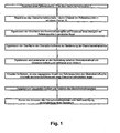
- FIG. 1 Fig. 3 shows a flowchart of one embodiment of the method of the present invention.
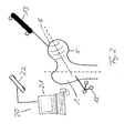
- an IR radiation-reflecting or emitting reference star 12 is arranged on the femoral neck bone 1, the position of which can be determined by an IR camera 22 of a navigation system 20.
- a pointer 13 the surface of the milled femoral head 6 is scanned and reference points 5 of the femoral head 6 are detected.
- the position of the reference points in space is determined by the navigation system 20.
- the femur 1 can be registered.
- the surface of the femoral head 6 is digitized by forming a virtual model of the femoral head 6.
- a shape or surface is approximated to the determined reference points 5 and this shape, such as a spherical shape, is fitted between the determined reference points 5 such that the average error or the mean distance of the reference points 5 from the surface of the sphere becomes minimal.
- the surface of the femoral neck 1 is digitized on the thigh neck 1 on the basis of the detected and determined reference points 5. From the digitized model of the femoral neck 1, the femoral neck axis 2 of the model is determined.
- a connecting plane 8 is determined, which runs through the connection between the femoral head 6 and thigh neck 1.
- a three-dimensional coordinate system as in FIG. 3B to see is determined.
- calculations of the navigation system 20 are performed.
- the navigation system 20 can calculate whether a predetermined number of reference points 5 of the femoral head 6 is within the inner diameter of the femoral implant 7. If more reference points 5 of the femoral head 6 within the femoral implant 7 than a predetermined threshold, the thigh implant 7 has a sufficient size, so that the selected size and the selected position of the femoral implant 6 are classified as appropriate and the data of the femoral implant 7 are output.
- the femoral implant 7 is displaced anteriorly, superiorly, posteriorly or inferiorly so that the central axis or femoral neck axis 2 does not translate, but, as in FIG FIG. 3A their spatial position is changed or rotated.
- the plane 8 is also rotated. In this new position of the femoral implant 7 it is again determined whether the predetermined threshold value is exceeded or undershot.
- this position of the femoral implant 7 is assumed to be an impossible or suitable position for positioning the examined surface implant 7.
- the size or inner diameter of the femoral implant 7 is virtually increased and it is again checked in the possible positions whether the threshold value of the larger model of the surface implant is exceeded or undershot.
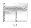
- FIG. 4 shows the sequence of possible displacements or repositioning of a femoral implant 7 of a certain size.
- the model of surface implant 7 of one size can be used in all in FIG. 4 moved positions are shown and tested there to the Threshold exceeded.
- the letter “H” denotes a displacement in the head direction
- the letter “F” a shift in the foot direction
- the letter “A” anterior displacement and the letter “P” a displacement posterior, respectively starting from the previous position of the model of the femoral implant 7.
- the numerical values indicate how much or by how many units the femoral implant 7 is displaced in the selected direction.
Description
Die vorliegende Erfindung betrifft ein Verfahren und eine Vorrichtung zur Auswahl eines Oberschenkelimplantats, welches bei Hüftgelenksoperationen vorzugsweise auf einen Oberschenkelkopf aufzementiert wird, wobei mittels dem erfindungsgemäßen Verfahren und der erfindungsgemäßen Vorrichtung ein passendes Oberschenkelimplantat basierend auf virtuellen oder digitalen Modellen eines Oberschenkelhalses und/oder eines Oberschenkelkopfes eines Patienten ermittelt oder ausgewählt wird.The present invention relates to a method and a device for selecting a femoral implant, which is preferably cemented to a femoral head in hip joint surgery, wherein by means of the inventive method and apparatus according to the invention a suitable thigh implant based on virtual or digital models of a femoral neck and / or a femoral head of a Patient is detected or selected.
Bei Hüftgelenksoperationen wird üblicherweise der Oberschenkelhals beibehalten und der Oberschenkelkopf abgefräst, um einen Oberflächenersatz des Oberschenkelkopfes oder ein Oberschenkelimplantat auf oder in den Oberschenkelkopf auf- bzw. einzuzementieren. Wird ein zu kleines Oberschenkelimplantat oder ein Oberschenkelimplantat mit einem zu kleinen Innendurchmesser gewählt und aufzementiert, besteht die Gefahr, dass sich der Fräser zur Bearbeitung der lmplantatinnenkontur unbeabsichtigt in den Oberschenkelhals einfräst, so dass es zu einer Oberschenkelhalsfraktur kommen kann. Wird ein zu großes Oberschenkelimplantat gewählt, so schließt das Oberschenkelimplantat nicht ausreichend mit dem Oberschenkelkopf oder an dem Oberschenkelhals ab.In hip joint surgery, the femoral neck is usually maintained and the femoral head is milled to cement or cement a femoral head resurfacing or a femoral implant onto or into the femoral head. If a too small femoral implant or a femoral implant with a too small inner diameter is selected and cemented, there is a risk that the cutter for machining the implant inner contour inadvertently milled into the femoral neck, so that it can lead to a femoral neck fracture. If too large a femoral implant is chosen, the femoral implant does not close sufficiently with the femoral head or neck.
Bei herkömmlichen Verfahren wird die Implantatsgröße präoperativ mittels Röntgenstrahlen und Vorlagen bestimmt. Dieses Vorgehen ist zeitaufwändig und enthält eine Vielzahl möglicher Ungenauigkeiten aufgrund von Projektionsfehlern. Intraoperativ wird die bestimmte Größe mittels Messlehren oder Metallvorlagen überprüft, was einen zusätzlichen Zeitaufwand hervorruft.In conventional methods, the implant size is determined preoperatively using X-rays and templates. This procedure is time consuming and contains a variety of possible inaccuracies due to projection errors. Intraoperatively, the specific size is checked by means of gauges or metal templates, which causes an additional expenditure of time.
Es ist eine Aufgabe der vorliegenden Erfindung die Nachteile aus dem Stand der Technik zu überwinden. Es ist weiter eine Aufgabe der vorliegenden Erfindung eine Vorrichtung und ein Verfahren bereitzustellen, welche eine schnelle und genaue Ermittlung eines passenden Oberschenkelimplantats ermöglichen.It is an object of the present invention to overcome the disadvantages of the prior art. It is a further object of the present invention to provide an apparatus and method that enables rapid and accurate determination of a suitable femoral implant.
Diese Aufgabe wird durch den Gegenstand der unabhängigen Ansprüche gelöst. Vorteilhafte Ausführungsformen ergeben sich aus den abhängigen Ansprüchen.This object is solved by the subject matter of the independent claims. Advantageous embodiments will be apparent from the dependent claims.
Bei dem erfindungsgemäßen Verfahren wird ein Oberschenkelimplantat oder ein Oberschenkelkopfersatz oder -aufsatz aus Modellen eines Oberschenkelhalses und/oder eines Oberschenkelkopfes eines Patienten ermittelt. Dabei werden berührungslos oder mittels Berührung oder Abtastung, zum Beispiel mittels eines Laser-Pointers oder eines mit mechanischen Berührungen arbeitenden Pointers, Referenzpunkte, insbesondere anatomische Landmarken, an oder auf dem Oberschenkelhals oder dem Oberschenkelkopf des Patienten erfasst. Dabei ist an dem Oberschenkelhals ein, insbesondere IR-Strahlung emittierender oder reflektierender Referenzstern angeordnet, welcher von einer Kamera, insbesondere einer IR-Kamera, eines Navigationssystems erfasst werden kann und dessen dreidimensionale Raumposition relativ zu einem Referenzkoordinatensystem mittels des Navigationssystems ermittelt werden kann. Aus den erfassten Referenzpunkten des Oberschenkelhalses und/oder des Oberschenkelkopfes kann das Navigationssystem basierend auf den ermittelten dreidimensionalen Raumpositionen des Referenzsterns dreidimensionale Referenzpunkt-Raumpositionen der erfassten Referenzpunkte relativ zu dem Referenzkoordinatensystem, wie dem Referenzstern oder dem Ursprung des Referenzsterns, ermitteln, so dass der Oberschenkelhals und/oder der Oberschenkelkopf bezüglich des Referenzkoordinatensystems, wie dem Referenzstern, registriert werden können.In the method according to the invention, a femoral implant or a femoral head replacement or attachment of models of a femoral neck and / or a femoral head of a patient is determined. In this case, reference points, in particular anatomical landmarks, are detected on or on the thigh neck or the thigh head of the patient without contact or by means of contact or scanning, for example by means of a laser pointer or a pointer working with mechanical contacts. Here, a, in particular IR radiation emitting or reflecting reference star is arranged on the thigh neck, which can be detected by a camera, in particular an IR camera, a navigation system and its three-dimensional spatial position can be determined relative to a reference coordinate system by means of the navigation system. Based on the determined three-dimensional spatial positions of the reference star, the navigation system can determine three-dimensional reference-point spatial positions of the detected reference points relative to the reference coordinate system, such as the reference star or the origin of the reference star, so that the femoral neck and the femoral neck can be determined from the detected reference points of the femoral neck and / or thigh head / or the femoral head can be registered with respect to the reference coordinate system, such as the reference star.
Aus den ermittelten dreidimensionalen Referenzpunkt-Raumpositionen wird ein Modell des Oberschenkelhalses und/oder des Oberschenkelkopfes, wie ein virtuelles oder digitales Modell des Oberschenkelhalses und/oder des Oberschenkelkopfes, ermittelt. Zum Beispiel können die Modelle ermittelt werden, indem die ermittelten Referenzpunkt-Raumpositionen zu einer durchgehenden oder durchgängigen Form oder Oberfläche verbunden werden, oder indem aus den ermittelten Referenzpunkt-Raumpositionen eine Form oder Oberfläche des Oberschenkelhalses und/oder des Oberschenkelkopfes angenähert wird. Das Modell des proximalen Femur mit Oberschenkelkopf und Schenkelhals wird insbesondere dadurch ermittelt, dass die ermittelten Referenzpunkt-Raumkoordinaten zu einer Form verbunden werden, welche insbesondere eine Kugelform besitzt. Aus dem erstellten Modell des Oberschenkelkopfes kann eine Grund- oder Ausgangsgröße eines Modells des Oberschenkelimplantats ermittelt werden. Beispielsweise kann aus der Größe des Oberschenkelkopfes oder aus dem Durchmesser des Modells des Oberschenkelkopfes auf die Größe des Modells des Oberschenkelimplantats geschlossen werden. Insbesondere kann der Durchmesser des Modells des Oberschenkelkopfes als Grundgröße oder als Grundwert des Innendurchmessers des Modells des Oberschenkelimplantats verwendet werden. Basierend auf dem ermittelten Grundwert des Innendurchmessers des Modells des Oberschenkelimplantats oder der ermittelten Grundgröße kann ein Modell des Oberschenkelimplantats bestimmt werden. Dabei wird vorzugsweise das Ausgangsmodell des Oberschenkelimplantats nicht mit der Grundgröße oder dem ermittelten Grundwert erstellt, sondern es wird vorzugsweise eine Startgröße oder ein Startwert des Innendurchmessers des Modells des Oberschenkelimplantats verwendet, welcher um einen vorgegebenen Wert von dem Grundwert oder der Grundgröße abweicht und insbesondere um einen vorgegebenen Wert kleiner ist als der Grundwert oder die Grundgröße. Beispielsweise kann als Startgröße des Modells des Oberschenkelimplantats eine Größe gewählt werden, welche um eine Größeneinheit oder zwei oder mehr Größeneinheiten kleiner ist als die Grundgröße des Modells des Oberschenkelimplantats, welche aus der Größe des Oberschenkelkopfes ermittelt wurde. Auch kann als Startwert des Innendurchmessers des Modells des Oberschenkelimplantats ein Wert verwendet werden, welcher um eine Einheit oder zwei oder mehr Einheiten kleiner ist als der Grundwert des Innendurchmessers des Modells des Oberschenkelimplantats, welcher aus dem Innendurchmesser des Oberschenkelkopfes ermittelt wurde und vorzugsweise dem Innendurchmesser des Oberschenkelkopfes entspricht.From the determined three-dimensional reference point spatial positions, a model of the femoral neck and / or the femoral head, such as a virtual or digital model of the femoral neck and / or the femoral head, is determined. For example, the models may be determined by connecting the determined reference spatial positions to a continuous or continuous shape or surface, or approximating a shape or surface of the femoral neck and / or femoral head from the determined reference spatial positions. The model of the proximal femur with femoral head and femoral neck is determined, in particular, by the fact that the determined reference point spatial coordinates are connected to form, which in particular has a spherical shape. From the created model of the femoral head a basic or initial size of a model of the femoral implant can be determined. For example, from the size of the Thigh head or from the diameter of the model of the femoral head to the size of the model of the femoral implant. In particular, the diameter of the model of the femoral head can be used as the basic size or as the basic value of the inner diameter of the model of the femoral implant. Based on the determined basic value of the inner diameter of the model of the femoral implant or the determined basic size, a model of the femoral implant can be determined. In this case, preferably the starting model of the femoral implant is not created with the basic size or the determined basic value, but preferably a starting variable or a starting value of the inner diameter of the model of the femoral implant is used which deviates from the basic value or the basic quantity by a predetermined value and in particular by one given value is smaller than the basic value or the basic size. For example, a size which is smaller than the basic size of the model of the thigh implant, which was determined from the size of the femoral head, may be selected as the starting variable of the model of the femoral implant. Also, as a starting value of the inner diameter of the femoral implant model, a value smaller by one unit or two or more units than the inner diameter of the thigh implant model determined from the inner diameter of the femoral head and preferably the inner diameter of the femoral head may be used equivalent.
Das ermittelte virtuelle oder digitale Modell des Oberschenkelimplantats wird in dem virtuellen oder digitalen Modell des Oberschenkelkopfes platziert oder positioniert oder auf diesem virtuell aufzementiert. In der aufzementierten Position wird mittels des Navigationssystems ermittelt, ob mit dem Startwert eine passende Größe des Implantats gewählt wurde. Hierfür kann zum Beispiel ein absoluter Implantatwert ermittelt werden, welcher angibt, wie viele der ermittelten Referenzpunkt-Raumpositionen oder der Punkte des Modells des Oberschenkelkopfes innerhalb oder außerhalb des Modells des Oberschenkelimplantats liegen. Auch kann als absoluter Implantatwert ein Wert ermittelt werden, welcher angibt, wie viele der ermittelten Referenzpunkt-Raumpositionen oder der Punkte des Modells des Oberschenkelkopfes innerhalb oder außerhalb des Innendurchmessers des Modells des Oberschenkelimplantats liegen. Auch kann ein relativer Implantatwert ermittelt werden, welcher angibt, welcher Anteil der ermittelten Referenzpunkt-Raumpositionen oder der Punkte des Oberschenkelkopfes innerhalb oder außerhalb des Modells des Oberschenkelimplantats liegt oder welcher angibt, welcher Anteil der ermittelten Referenzpunkt-Raumpositionen oder Punkte des Modells des Oberschenkelkopfes innerhalb oder außerhalb des Innendurchmessers des Modells des Oberschenkelimplantats liegt. Vorzugsweise wird ein absoluter Implantatwert ermittelt, welcher angibt, wie viele der Referenzpunkt-Raumpositionen außerhalb des Innendurchmessers des Modells des Oberschenkelimplantats liegen oder ein relativer Implantatwert, welcher angibt, welcher Anteil der ermittelten Referenzpunkt-Raumpositionen außerhalb des Innendurchmessers des Modells des Oberschenkelimplantats liegt.The determined virtual or digital model of the femoral implant is placed in the virtual or digital model of the femoral head or positioned or virtually cemented on this. In the cemented position, it is determined by means of the navigation system whether a suitable size of the implant has been selected with the starting value. For this purpose, for example, an absolute implant value can be determined, which indicates how many of the determined reference point spatial positions or the points of the model of the femoral head lie inside or outside the model of the femoral implant. Also, as absolute implant value, a value may be determined which indicates how many of the determined reference point spatial positions or the points of the model of the femoral head are inside or outside the inner diameter of the model of the femoral implant. Also, a relative implant value can be determined, which indicates what proportion of the determined reference point spatial positions or the points of the femoral head inside or outside of the Model of the femoral implant or which indicates what proportion of the determined reference point spatial positions or points of the model of the femoral head is inside or outside the inner diameter of the model of the femoral implant. Preferably, an absolute implant value is determined, which indicates how many of the reference point spatial positions are outside the inner diameter of the model of the femoral implant or a relative implant value, which indicates which proportion of the determined reference point spatial positions lies outside the inner diameter of the model of the femoral implant.
Der ermittelte Implantatwert wird mit einem vorgegebenen oder einem, zum Beispiel aus dem Grundwert des Oberschenkelimplantats abgeleiteten, Grenzwert verglichen. Wird bei einem Implantatwert, welcher angibt, wie viele oder welcher Anteil der ermittelten Referenzpunkt-Raumpositionen außerhalb des Innendurchmessers des Modells des Oberschenkelimplantats liegen bzw. liegt, der Grenzwert überschritten, so kann daraus geschlossen werden, dass das gewählte Modell des Oberschenkelimplantats zu klein für den vorhandenen Oberschenkelkopf ist oder an einer falschen Position angeordnet ist. In diesem Fall, kann das Modell des Oberschenkelimplantats virtuell, beispielsweise durch Verschieben, in eine weitere vorgegebene oder ermittelbare Position gebracht werden. In dieser neuen Position des Modells des Oberschenkelimplantats wird wiederum ein Implantatwert ermittelt, welcher mit dem vorgegebenen Grenzwert verglichen wird, wobei wieder aus dem Vergleich mit dem Grenzwert geschlossen werden kann, ob eine passende Größe und Position des Oberschenkelimplantats gefunden wurde oder ob das Oberschenkelimplantat wieder neu positioniert werden soll und wiederum auf passende Größe und Form überprüft werden soll. Bei einer Unterschreitung des Grenzwertes wird darauf geschlossen, dass das Modell des Oberschenkelimplantats eine richtige Größe aufweist und richtig positioniert ist, so dass unter Berücksichtigung dieser Daten ein Operateur oder Chirurg ein Oberschenkelimplantat beispielsweise mit der ermittelten Größe an der ermittelten Position positionieren kann.The determined implant value is compared with a predetermined or derived, for example, from the basic value of the femoral implant, limit. If, in the case of an implant value which indicates how many or which proportion of the determined reference point spatial positions lies outside the inner diameter of the model of the femoral implant, the limit value is exceeded, then it can be concluded that the selected model of the femoral implant is too small for the implant existing thigh head or is located in a wrong position. In this case, the model of the femoral implant can be brought virtually, for example by moving, in another predetermined or determinable position. In this new position of the model of the femoral implant again an implant value is determined, which is compared with the predetermined limit, again it can be concluded from the comparison with the limit, if a suitable size and position of the femoral implant was found or if the femoral implant again should be positioned and checked again for appropriate size and shape. If the limit value is undershot, it is concluded that the model of the femoral implant has a correct size and is positioned correctly, so that, taking into account this data, a surgeon or surgeon can position a femoral implant of the determined size, for example, at the determined position.
Wird in keiner der Positionen der Grenzwert unterschritten oder wird in jeder Position der Grenzwert überschritten, so wird bevorzugt ein neues Modell des Oberschenkelimplantats mit einer größeren Größe oder einem größeren Innendurchmesser als der vorhergehenden Größe bzw. dem vorhergehenden Innendurchmesser berechnet. Beispielsweise kann der Innendurchmesser des Modells des Oberschenkelimplantats um eine oder zwei oder mehr Einheiten vergrößert werden. Das größere Modell des Oberschenkelimplantats wird vorzugsweise wiederum positioniert und auf seine Größe und Position mittels des Implantatwerts an verschiedenen Positionen überprüft.If the limit value is not underrun in any of the positions or if the limit value is exceeded in each position, then a new model of the femoral implant having a larger size or a larger inner diameter than the preceding size or the preceding inner diameter is preferably calculated. For example, the inner diameter of the model of the femoral implant can be increased by one or two or more units. The larger model of the femoral implant will preferably again positioned and checked for its size and position by means of the implant value at different positions.
Beispielsweise kann die Ermittlung eines passenden Modells des Oberschenkelimplantats solange durchgeführt werden, bis ein passendes oder das erste passende Oberschenkelimplantat gefunden wird oder es können alle passenden Größen und Positionen des Oberschenkelimplantats ermittelt werden, welche die vorgegebenen Grenzwerte einhalten, wobei aus allen passenden Modellen ein ideales Oberschenkelimplantat von dem Navigationssystem ausgewählt und vorgeschlagen werden kann und/oder von einem Operateur gewählt werden kann.For example, the determination of an appropriate model of the femoral implant may be made until a matching or first fitting femoral implant is found, or all appropriate sizes and positions of the femoral implant can be determined that meet the prescribed limits, with an ideal femoral implant of all matching models can be selected and proposed by the navigation system and / or can be selected by a surgeon.
Vorzugsweise wird auch aus den ermittelten Referenzpunkt-Raumpositionen, insbesondere aus denen auf dem Oberschenkelhals ermittelten Referenzpunkt-Raumpositionen, ein Modell der Oberschenkelhalsachse des Oberschenkelhalses bestimmt. Das Modell der Oberschenkelhalsachse wird dabei vorzugsweise als Schnittgerade mindestens zweier Ebenen berechnet. Beispielsweise können die Ebenen anterior, posterior, inferior oder superior durch den Körper des Patienten verlaufende Ebenen sein.Preferably, a model of the femoral neck axis of the femoral neck is also determined from the determined reference point spatial positions, in particular from those determined on the femoral neck reference point spatial positions. The model of the femoral neck axis is preferably calculated as the cutting line of at least two planes. For example, the planes may be anterior, posterior, inferior, or superior through the body of the patient.
Auch kann aus den Referenzpunkt-Raumpositionen, insbesondere den Referenzpunkt-Raumpositionen an der Schnittstelle zwischen Oberschenkelhals und Oberschenkelknochen, in den Modellen des Oberschenkelhalses und des Oberschenkelknochens ein Modell einer Ebene durch die Verbindung zwischen Oberschenkelhals und Oberschenkelknochen ermittelt werden, welche zum Beispiel mit der Oberschenkelhalsachse ein dreidimensionales Koordinatensystem aufspannen oder bilden kann, welches als Koordinatensystem verwendet werden kann, bezüglich dessen Berechnungen, wie die Implantatwertberechnungen, des Navigationssystems ausgeführt werden können.Also, from the reference point spatial positions, in particular the reference point spatial positions at the interface between femoral neck and femur, in the models of femoral neck and femur, a model of a plane through the connection between femoral neck and femur can be determined, which, for example, with the femoral neck axis span or form a three-dimensional coordinate system that can be used as a coordinate system with respect to which calculations, such as the implant value calculations, of the navigation system can be performed.
Zur Neupositionierung des Modells des Oberschenkelimplantats zur Ermittlung einer geeigneten Position oder einer passenden Position des Oberschenkelimplantats kann das Modell des Oberschenkelimplantats verschoben werden. Vorzugsweise wird das Modell des Oberschenkelimplantats so verschoben, dass die Mittelachse oder die Oberschenkelhalsachse durch das Implantat und den Oberschenkelkopf nicht translatorisch verschoben wird oder keine translatorische Bewegung ausführt. Bevorzugt wird das Modell des Oberschenkelimplantats in eine Richtung, insbesondere anterior, superior, posterior oder inferior, verschoben, welche senkrecht zu dem Modell der Oberschenkelhalsachse ist, so dass es senkrecht zu der Mittelachse bzw. Oberschenkelhalsachse translatorisch bewegt wird, nicht jedoch entlang der Mittelachse bzw. Oberschenkelhalsachse. Somit kann das Modell des Oberschenkelimplantats umpositioniert oder neu positioniert werden, indem die Lage des Modells der Oberschenkelhalsachse in dem Modell des Oberschenkelhalses und/oder des Oberschenkelkopfes geändert wird.To reposition the femoral implant model to determine a suitable position or position of the femoral implant, the femoral implant model may be displaced. Preferably, the model of the femoral implant is displaced so that the central axis or the femoral neck axis is not translationally displaced by the implant and the femoral head or performs no translational movement. The model of the femoral implant is preferred in one direction, in particular anterior, superior, posterior or inferior, which is perpendicular to the model of the femoral neck axis, so that it is translationally moved perpendicular to the central axis or femoral neck axis, but not along the central axis or femoral neck axis. Thus, the model of femoral implant can be repositioned or repositioned by changing the location of the femoral neck axis model in the femoral neck and / or femoral head model.
Die Erfindung bezieht sich des Weiteren auf ein Computerprogramm, welches, wenn es in einen Computer geladen wird oder auf einem Computer läuft, ein wie oben beschriebenes Verfahren durchführt. Weiterhin bezieht sich die Erfindung auf ein Programmspeichermedium oder ein Computerprogrammprodukt mit einem solchen Programm.The invention further relates to a computer program which, when loaded into a computer or running on a computer, performs a method as described above. Furthermore, the invention relates to a program storage medium or a computer program product with such a program.
Die erfindungsgemäße Vorrichtung umfasst ein Navigationssystem mit mindestens einer Kamera, insbesondere einer IR-Kamera, eine Erfassungseinheit, welche mit dem Navigationssystem drahtlos oder drahtgebunden verbunden oder in das Navigationssystem integriert sein kann, sowie eine Recheneinheit, welche mit dem Navigationssystem drahtlos oder drahtgebunden verbunden oder in das Navigationssystem integriert sein kann. Mit der Erfassungseinheit, wie einem Pointer oder Laser-Pointer oder einer Kamera, werden Referenzpunkte auf einem Oberschenkelhals und/oder einem Oberschenkelkopf eines Patienten erfasst oder detektiert, wobei insbesondere anatomische Landmarken des Oberschenkelhalses und/oder des Oberschenkelkopfes erfasst werden. Mit der Kamera des Navigationssystems kann die Position eines an dem Oberschenkelhals angeordneten Referenzsterns, insbesondere eines Infrarot-Strahlung emittierenden oder reflektierenden Referenzsterns, im Raum erfasst oder verfolgt werden.The device according to the invention comprises a navigation system with at least one camera, in particular an IR camera, a detection unit, which can be wirelessly or wired connected to the navigation system or integrated into the navigation system, as well as a computing unit which is wirelessly or wired connected to the navigation system or in the navigation system can be integrated. With the detection unit, such as a pointer or laser pointer or a camera, reference points on a femoral neck and / or a femoral head of a patient are detected or detected, in particular anatomical landmarks of the femoral neck and / or the femoral head are detected. The position of a reference star arranged on the thigh neck, in particular of a reference star emitting or reflecting infrared radiation, can be detected or tracked in space with the camera of the navigation system.
Mit der Recheneinheit werden aus den erfassten Referenzpunkten unter Berücksichtigung der ermittelten Positionen des Referenzsterns dreidimensionale Referenzpunkt-Raumpositionen der erfassten Referenzpunkte ermittelt mittels derer der Oberschenkelhals und/oder der Oberschenkelkopf registriert werden können. Aus den registrierten Daten oder den dreidimensionalen Referenzpunkt-Raumpositionen erstellt die Recheneinheit ein Modell des Oberschenkelhalses und/oder des Oberschenkelkopfes, wie einen kugelförmigen Oberschenkelkopf, oder erstellt ein angenähertes virtuelles oder digitales Modell des Oberschenkelhalses und/oder des Oberschenkelkopfes. Basierend auf dem erstellten Modell des Oberschenkelkopfes bestimmt die Recheneinheit eine Grundgröße eines Modells des Oberschenkelimplantats. Zum Beispiel kann die Recheneinheit aus den Referenzpunkt-Raumpositionen den Durchmesser des Oberschenkelkopfes berechnen und diesen für die Ermittlung der Grundgröße des Modells des Oberschenkelimplantates verwenden. Vorzugsweise wird als Grundwert des Innendurchmessers des Modells des Oberschenkelimplantats der ermittelte Durchmesser des Oberschenkelkopfes verwendet. Basierend auf der ermittelten Grundgröße des Oberschenkelimplantats erstellt die Recheneinheit ein Modell des Oberschenkelimplantats. Bevorzugt kann als Startwert oder Startgröße des Modells des Oberschenkelimplantats eine von der Grundgröße abweichende Startgröße verwendet werden, welche vorzugsweise um eine oder zwei oder mehr Einheiten kleiner ist als die Grundgröße des Modells des Oberschenkelimplantats. Insbesondere kann als Startwert des Innendurchmessers des Modells des Oberschenkelimplantats ein von dem ermittelten Grundwert des Innendurchmessers abweichender Innendurchmesser verwendet werden, wobei als Startwert des Innendurchmessers des Modells des Oberschenkelimplantats vorzugsweise ein um ein, zwei oder mehr Einheiten kleinerer Innendurchmesser von der Recheneinheit verwendet wird.With the arithmetic unit, taking into account the determined positions of the reference star, three-dimensional reference point spatial positions of the detected reference points can be determined from the detected reference points by means of which the thigh neck and / or the thigh head can be registered. From the registered data or the three-dimensional reference point spatial positions, the arithmetic unit creates a model of the femoral neck and / or femoral head, such as a spherical femoral head, or creates an approximate virtual or digital model of the femoral neck and / or femoral head. Based on the created model of the femoral head, the arithmetic unit determines a basic size of a model of the femoral implant. For example, the arithmetic unit may calculate the diameter of the femoral head from the reference point spatial positions and use this to determine the basic size of the model of the femoral implant. The determined diameter of the thigh head is preferably used as the basic value of the inner diameter of the model of the thigh implant. Based on the determined basic size of the femoral implant, the arithmetic unit creates a model of the femoral implant. Preferably, the starting value or starting variable of the model of the femoral implant may be a start size deviating from the basic size, which is preferably smaller by one or two or more units than the basic size of the model of the femoral implant. In particular, as an initial value of the inner diameter of the model of the femoral implant, an inner diameter differing from the determined basic value of the inner diameter can be used, wherein as initial value of the inner diameter of the model of the femoral implant, preferably one, two or more units of smaller inner diameter are used by the arithmetic unit.
Das mit den Startwerten oder der Startgröße erstellte Modell des Oberschenkelimplantats wird virtuell von der Recheneinheit in oder an dem Modell des Oberschenkelkopfes platziert oder positioniert, wobei diese virtuelle Positionierung auch grafisch auf einer Anzeigevorrichtung dargestellt werden kann. Weiter werden mit der Recheneinheit die ermittelten Referenzpunkt-Raumpositionen oder Punkte des Modells des Oberschenkelkopfes mit dem Modell des Oberschenkelimplantats verglichen, wobei insbesondere ermittelt wird, ob das Modell des Oberschenkelimplantats ausreichend groß für das Modell des Oberschenkelkopfes ist. Dabei wird bevorzugt von der Recheneinheit ein Implantatwert ermittelt, welcher angibt, wie viele oder welcher Anteil der ermittelten Referenzpunkt-Raumpositionen oder Punkte des Modells des Oberschenkelkopfes außerhalb des Modells des Oberschenkelimplantats liegen bzw. liegt oder außerhalb des Innendurchmessers des Oberschenkelimplantats liegen bzw. liegt. Liegt der ermittelte Implantatwert über einem vorgegebenen Grenzwert, so wird das Modell des Oberschenkelimplantats umpositioniert und es wird ein neuer Implantatwert ermittelt oder es wird ein größeres Modell des Oberschenkelimplantats ermittelt und dessen Implantatwert wird vorzugsweise an verschiedenen Positionen bestimmt. Die Recheneinheit stellt eine passende oder mögliche Größe und Position des Oberschenkelimplantats vorzugsweise dann fest, wenn der Implantatwert den Grenzwert nicht überschreitet. Das passende Oberschenkelimplantat wird oder die passenden Oberschenkelimplantate werden von der Recheneinheit vorzugsweise auf einer Anzeigevorrichtung ausgegeben oder dargestellt, so dass ein Operateur das ideale Oberschenkelimplantat auswählen kann.The model of the femoral implant created with the starting values or the starting size is virtually placed or positioned by the arithmetic unit in or on the model of the femoral head, whereby this virtual positioning can also be displayed graphically on a display device. Further, with the arithmetic unit, the determined reference point spatial positions or points of the model of the femoral head are compared with the model of the femoral implant, wherein in particular it is determined whether the model of the femoral implant is sufficiently large for the model of the femoral head. In this case, an implant value is preferably determined by the arithmetic unit, which indicates how many or which proportion of the determined reference point spatial positions or points of the model of the femoral head are outside the model of the femoral implant or lies outside the inner diameter of the femoral implant. If the determined implant value is above a predetermined limit, the model of the femoral implant is repositioned and a new implant value is determined or a larger model of the femoral implant is determined and its implant value is preferably determined at different positions. The arithmetic unit preferably determines a suitable or possible size and position of the femoral implant if the implant value does not exceed the limit value. The fitting Thigh implant or the appropriate femoral implants are preferably output or displayed by the computing unit on a display device so that a surgeon can select the ideal femoral implant.
Die Erfindung wird nachfolgend anhand bevorzugter Ausführungsformen beschrieben werden. Es zeigen:
Figur 1- ein Ablaufdiagramm einer Ausführungsform des erfindungsgemäße Verfahrens;
Figur 2- die Erfassung von Referenzpunkten eines Oberschenkelkopfes;
- Figur 3
- ein virtuelles Modell des Oberschenkelhalses, des Oberschenkelkopfes und des Oberschenkelimplantats;
- Figur 3A
- das virtuelle Koodinatensystem der Anordnung aus
Figur 3A ; und - Figur 4
- ein Ablaufdiagram für Neupositionierungen gemäß einer Ausführungsform des erfindungsgemäßen Verfahrens.
- FIG. 1
- a flowchart of an embodiment of the method according to the invention;
- FIG. 2
- the detection of reference points of a femoral head;
- FIG. 3
- a virtual model of the femoral neck, femoral head, and thigh implant;
- FIG. 3A
- the arrangement's virtual coordinate system
FIG. 3A ; and - FIG. 4
- a flow chart for repositioning according to an embodiment of the method according to the invention.
Aus den erfassten Punkten oder Landmarken an der Verbindung zwischen Oberschenkelkopf 6 und Oberschenkelhals 1 wird eine Verbindungsebene 8 ermittelt, welche durch die Verbindung zwischen Oberschenkelkopf 6 und Oberschenkelhals 1 verläuft. Durch die Ebene 8 werden zwei Raumrichtungen definiert, so dass aus der Ebene 8 und der Oberschenkelhalsachse 2 ein dreidimensionales Koordinatensystem, wie in
Alle Größen und Formen, bei denen ermittelt wird, dass ausreichend viele Referenzpunkte 5 des Oberschenkelkopfes 6 innerhalb des Innendurchmessers des Oberschenkelimplantats 7 liegen, werden als passende Größen und Formen und Positionen des Oberschenkelimplantats 7 angenommen und ausgegeben. Aus diesen ausgegebenen passenden Größen und Positionen des Oberschenkelimplantats 7 kann der Operateur das ideale Oberschenkelimplantat 7 auswählen und einsetzen.All sizes and shapes in which it is determined that a sufficient number of
Claims (19)
- A method for selecting a femoral implant (7) on the basis of models of a femoral neck (1) and/or a femoral head (6) of a patient, comprising the following steps:a) detecting reference points (5), in particular anatomical landmarks, on the femoral neck (1) and/or femoral head (6) of the patient;b) registering the femoral neck (1) and/or femoral head (6) on the basis of three-dimensional reference point spatial positions of the detected reference points (5);c) producing a model of the femoral neck (1) and/or femoral head (6) from the three-dimensional reference point spatial positions;d) ascertaining a base size of a model of the femoral implant (7) on the basis of the produced model of the femoral head (6);e) producing a model of the femoral implant (7) on the basis of the base size of the model of the femoral implant (7);f) positioning the model of the femoral implant (7) at a position in or on the model of the femoral head (6);g) ascertaining an implant value which indicates how many or what proportion of the ascertained reference point spatial positions are inside the model of the femoral implant (7);h) checking whether the implant value exceeds a predetermined limit value; andi) repositioning the model of the femoral implant (7) and performing Steps g) to i) if the implant value exceeds the limit value, or determining an appropriate size and position of the femoral implant (7) if the implant value does not exceed the limit value.
- The method according to the preceding claim, wherein Steps f) to i) are repeated using at least one other model of the femoral implant (7), different from the model based on the base size, in particular a larger model of the femoral implant (7).
- The method according to any one of the preceding claims, wherein the at least one other model of the femoral implant (7) exhibits a larger inner diameter than the model based on the base size.
- The method according to any one of the preceding claims, wherein the base value of the inner diameter of the model of the femoral implant (7) is used as the base size of the model of the femoral implant (7), wherein the diameter of the produced model of the femoral head (6) is used as the base value of the inner diameter of the femoral implant (7).
- The method according to the preceding claim, wherein the model of the femoral implant is produced using a starting value of the inner diameter of the model of the femoral implant (7), wherein the starting value of the inner diameter of the model of the femoral implant (7) deviates from the base value by a predetermined value and is in particular smaller than the base value by a predetermined value.
- The method according to any one of the preceding claims, wherein the implant value is ascertained as how many or what proportion of the ascertained reference point spatial positions are outside the inner diameter of the model of the femoral implant (7).
- The method according to any one of the preceding claims, wherein the model of the femoral head (6) is formed by ascertaining a shape, in particular a spherical shape, or a surface from the reference point spatial positions.
- The method according to any one of the preceding claims, wherein a model of the femoral neck axis (2) is ascertained from the reference point spatial positions.
- The method according to the preceding claim, wherein the model of the femoral neck axis (2) is ascertained as an intersecting straight line of at least two planes, wherein the planes run in particular anteriorly, superiorly, posteriorly and inferiorly through the patient.
- The method according to any one of the preceding claims, wherein from the reference point spatial positions, in particular reference point spatial positions of the connection between the femoral neck (1) and the femoral head, a plane through the connection between the femoral neck (1) and the femoral head (6) is ascertained in the models of the femoral neck (1) and the femoral head (6).
- The method according to any one of the preceding claims, wherein in order to reposition the model of the femoral implant (7), the model of the femoral implant (7) is shifted, in particular anteriorly, superiorly, posteriorly or inferiorly, in a direction which is perpendicular to the model of the femoral neck axis (2).
- The method according to any one of the preceding claims, wherein for repositioning, the model of the femoral implant (7) can be shifted in all degrees of freedom relative to the model of the femoral head (6).
- The method according to any one of the preceding claims, wherein in order to reposition the femoral implant (7), the position of the model of the femoral neck axis (2) is changed relative to the model of the femoral implant (7), in the model of the femoral neck (1).
- The method according to any one of the preceding claims, wherein a number of appropriate shapes and sizes of the femoral implant (7) are ascertained and outputted.
- The method according to any one of the preceding claims, wherein an ideally appropriate size and shape of the femoral implant (7) is ascertained and outputted.
- A computer program which, when it is running on a computer or is loaded onto a computer, performs the method according to any one of the preceding claims.
- A program storage medium or computer program product comprising the computer program according to the preceding claim.
- A device for selecting a femoral implant (7) on the basis of models of a femoral neck (1) and/or a femoral head (6) of a patient, comprising: a detection unit (13) for detecting ' reference points (5), in particular anatomical landmarks, on the femoral neck (1) and/or femoral head (6) of the patient; a navigation system (20) connected to the detection unit (13) and comprising at least one camera (22), in particular an infrared camera, for detecting the position of a reference star (12) arranged on the femoral neck (1); and a computational unit (21) connected to the navigation system (20), for:a) registering the femoral neck (1) and/or femoral head (6) on the basis of three-dimensional reference point spatial positions of the detected reference points (5);b) producing a model of the femoral neck (1) and/or femoral head (6) from the three-dimensional reference point spatial positions;c) ascertaining a base size of a model of the femoral implant (7) on the basis of the produced model of the femoral head (6);d) producing a model of the femoral implant (7) on the basis of the base size of the model of the femoral implant (7);e) ascertaining an implant value which indicates how many or what proportion of the ascertained reference point spatial positions are outside the inner diameter of the model of the femoral implant (7);f) checking whether the implant value exceeds a predetermined limit value; andg) determining an appropriate size and position of the femoral implant (7) if the implant value does not exceed the limit value.
- The device according to the preceding claim, comprising an output device, connected to the navigation system (20), for graphically displaying the models of the femoral neck (1), the femoral head (6) and the femoral implant (7).
Priority Applications (3)
| Application Number | Priority Date | Filing Date | Title |
|---|---|---|---|
| DE502006008018T DE502006008018D1 (en) | 2006-05-31 | 2006-05-31 | Method of selecting a femoral implant |
| EP06011218A EP1862151B1 (en) | 2006-05-31 | 2006-05-31 | Method for selection of an femoral implant |
| US11/755,024 US7822588B2 (en) | 2006-05-31 | 2007-05-30 | Surface replacement of a femoral head |
Applications Claiming Priority (1)
| Application Number | Priority Date | Filing Date | Title |
|---|---|---|---|
| EP06011218A EP1862151B1 (en) | 2006-05-31 | 2006-05-31 | Method for selection of an femoral implant |
Publications (2)
| Publication Number | Publication Date |
|---|---|
| EP1862151A1 EP1862151A1 (en) | 2007-12-05 |
| EP1862151B1 true EP1862151B1 (en) | 2010-10-06 |
Family
ID=37401555
Family Applications (1)
| Application Number | Title | Priority Date | Filing Date |
|---|---|---|---|
| EP06011218A Expired - Fee Related EP1862151B1 (en) | 2006-05-31 | 2006-05-31 | Method for selection of an femoral implant |
Country Status (3)
| Country | Link |
|---|---|
| US (1) | US7822588B2 (en) |
| EP (1) | EP1862151B1 (en) |
| DE (1) | DE502006008018D1 (en) |
Families Citing this family (13)
| Publication number | Priority date | Publication date | Assignee | Title |
|---|---|---|---|---|
| US9179983B2 (en) | 2007-08-14 | 2015-11-10 | Zimmer, Inc. | Method of determining a contour of an anatomical structure and selecting an orthopaedic implant to replicate the anatomical structure |
| FR2932674B1 (en) | 2008-06-20 | 2011-11-18 | Tornier Sa | METHOD FOR MODELING A GLENOIDAL SURFACE OF AN OMOPLATE, DEVICE FOR IMPLANTING A GLENOIDAL COMPONENT OF A SHOULDER PROSTHESIS, AND METHOD FOR MANUFACTURING SUCH COMPOUND |
| EP2216728B1 (en) * | 2009-02-04 | 2012-04-04 | BrainLAB AG | Method and device for determining a characteristic of an anatomical structure |
| FR2955481B1 (en) | 2010-01-27 | 2013-06-14 | Tornier Sa | DEVICE AND METHOD FOR GLENOIDAL CHARACTERIZATION OF PROSTHETIC OR RESURFACING OMOPLATE |
| WO2015071757A1 (en) | 2013-11-13 | 2015-05-21 | Tornier Sas | Shoulder patient specific instrument |
| EP3250104B1 (en) * | 2015-01-28 | 2019-03-06 | Brainlab AG | Light point identification method |
| EP3389513A1 (en) | 2015-12-16 | 2018-10-24 | Tornier, Inc. | Patient specific instruments and methods for joint prosthesis |
| AU2017248357B2 (en) * | 2016-04-07 | 2022-06-02 | Icahn School Of Medicine At Mount Sinai | Apparatus, method and system for providing customizable bone implants |
| CN105769393A (en) * | 2016-04-08 | 2016-07-20 | 罗佳 | Method and system for hip joint prosthesis matching |
| CN106205322A (en) * | 2016-08-22 | 2016-12-07 | 叶强 | Human synovial measurement for Evaluation system |
| EP3651662A1 (en) | 2017-07-11 | 2020-05-20 | Tornier, Inc. | Patient specific humeral cutting guides |
| WO2019014278A1 (en) | 2017-07-11 | 2019-01-17 | Tornier, Inc. | Guides and instruments for improving accuracy of glenoid implant placement |
| EP4356854A2 (en) * | 2019-04-16 | 2024-04-24 | Icahn School of Medicine at Mount Sinai | Custom hip design and insertability analysis |
Family Cites Families (11)
| Publication number | Priority date | Publication date | Assignee | Title |
|---|---|---|---|---|
| US5880976A (en) * | 1997-02-21 | 1999-03-09 | Carnegie Mellon University | Apparatus and method for facilitating the implantation of artificial components in joints |
| DE60109541T2 (en) * | 2000-09-18 | 2006-02-16 | Fuji Photo Film Co., Ltd., Minami-Ashigara | System for selecting, displaying and storing artificial bone templates and record carriers therefor |
| JP2003271749A (en) * | 2002-03-18 | 2003-09-26 | Fuji Photo Film Co Ltd | Surgical operation assistance system |
| GB2393625B (en) * | 2002-09-26 | 2004-08-18 | Internet Tech Ltd | Orthopaedic surgery planning |
| WO2005000140A2 (en) * | 2003-06-02 | 2005-01-06 | Murphy Stephen B | Virtual trial reduction system for hip arthroplasty and coordinate systems therefor |
| US20050065617A1 (en) * | 2003-09-05 | 2005-03-24 | Moctezuma De La Barrera Jose Luis | System and method of performing ball and socket joint arthroscopy |
| US20050281465A1 (en) * | 2004-02-04 | 2005-12-22 | Joel Marquart | Method and apparatus for computer assistance with total hip replacement procedure |
| FR2865928B1 (en) * | 2004-02-10 | 2006-03-17 | Tornier Sa | SURGICAL DEVICE FOR IMPLANTATION OF A TOTAL HIP PROSTHESIS |
| GB0420346D0 (en) * | 2004-09-13 | 2004-10-13 | Finsbury Dev Ltd | Tool |
| DE202005001127U1 (en) * | 2005-01-17 | 2005-06-02 | Aesculap Ag & Co. Kg | Device for displaying the position/orientation of a tool for preparing a femur for an implant comprises a data-processing system programmed so that it shows the joint ball in a transversal plane of the femur |
| DE202005001128U1 (en) * | 2005-01-17 | 2005-05-25 | Aesculap Ag & Co. Kg | Navigation system to determine the neutral position of the thigh bone relative to the pelvis for use in hip operations by using markers laid down on both bones to determine their position and orientation |
-
2006
- 2006-05-31 EP EP06011218A patent/EP1862151B1/en not_active Expired - Fee Related
- 2006-05-31 DE DE502006008018T patent/DE502006008018D1/en active Active
-
2007
- 2007-05-30 US US11/755,024 patent/US7822588B2/en not_active Expired - Fee Related
Also Published As
| Publication number | Publication date |
|---|---|
| EP1862151A1 (en) | 2007-12-05 |
| US7822588B2 (en) | 2010-10-26 |
| DE502006008018D1 (en) | 2010-11-18 |
| US20080009954A1 (en) | 2008-01-10 |
Similar Documents
| Publication | Publication Date | Title |
|---|---|---|
| EP1862151B1 (en) | Method for selection of an femoral implant | |
| EP1507472B1 (en) | Arrangement for interoperative determination of the position of an articular joint replacement implant | |
| EP1894538B1 (en) | Method and device for determining the position of pelvic planes | |
| EP2003616B1 (en) | Computer-assisted joint analysis with surface projection | |
| EP1402855B1 (en) | Device and method for determining the flexion angle of a joint | |
| EP1190675B1 (en) | System for navigation-assisted orientation of elements on a body | |
| EP1313400B1 (en) | Device for determining a load axis of an extremity | |
| DE102004052228B4 (en) | System and method for aligning image data with respect to intraoperatively digitized characteristics | |
| DE602004010365T2 (en) | METHOD AND DEVICE FOR RECORDING TOOL POSITIONING PARAMETERS OF A LOCALIZATION DEVICE | |
| DE112004002435B4 (en) | Determination of patient-related information on the position and orientation of MR images by individualizing a body model | |
| EP2593031B1 (en) | Optical method for determining the change of length of a leg | |
| EP1507488A1 (en) | Arrangement for determining function-determined geometric variables of a joint of a vertebrate | |
| EP2156805B1 (en) | Planning support for correcting joint elements | |
| EP2008606B1 (en) | Determination of correspondence object pairs for medical navigation | |
| WO2014008613A1 (en) | Method for generating a graphical 3d computer model of at least one anatomical structure in a selectable pre-, intra-, or postoperative status | |
| DE102008036764A1 (en) | System and method for planning a surgical procedure | |
| EP1955668B1 (en) | Method and device for the determination of alignment information during sonographically navigable repositioning of bone fragments | |
| EP1925256A1 (en) | Method and device for registering an anatomical structure with markers | |
| DE102010016386A1 (en) | Noninvasive method and apparatus for determining a reference plane of the human pelvis | |
| DE102016215831A1 (en) | Automatic generation of synthetic projections | |
| DE102017203438A1 (en) | A method for image support of a minimally invasive intervention with an instrument in an intervention area of a patient performing person, X-ray device, computer program and electronically readable data carrier | |
| DE102010041564A1 (en) | Orientation device for use in orthopedics or traumatology field for locating e.g. femur locking compression plate during femur fractures in patient, has orientation element comprising connection elements arranged at defined point at object | |
| EP2248484A1 (en) | Tool for recording levels of a bone and allocated data processing method | |
| EP1693798B1 (en) | Determination of the femoral shaft axis and the femoral neck axis and its 3D reconstruction | |
| EP1611863B1 (en) | Generation of a three-dimensional model of a body portion based on fluoroscopic image data and specific landmarks |
Legal Events
| Date | Code | Title | Description |
|---|---|---|---|
| PUAI | Public reference made under article 153(3) epc to a published international application that has entered the european phase |
Free format text: ORIGINAL CODE: 0009012 |
|
| 17P | Request for examination filed |
Effective date: 20060531 |
|
| AK | Designated contracting states |
Kind code of ref document: A1 Designated state(s): AT BE BG CH CY CZ DE DK EE ES FI FR GB GR HU IE IS IT LI LT LU LV MC NL PL PT RO SE SI SK TR |
|
| AX | Request for extension of the european patent |
Extension state: AL BA HR MK YU |
|
| AKX | Designation fees paid |
Designated state(s): DE FR GB IT |
|
| RAP1 | Party data changed (applicant data changed or rights of an application transferred) |
Owner name: BRAINLAB AG |
|
| GRAP | Despatch of communication of intention to grant a patent |
Free format text: ORIGINAL CODE: EPIDOSNIGR1 |
|
| GRAS | Grant fee paid |
Free format text: ORIGINAL CODE: EPIDOSNIGR3 |
|
| GRAA | (expected) grant |
Free format text: ORIGINAL CODE: 0009210 |
|
| AK | Designated contracting states |
Kind code of ref document: B1 Designated state(s): DE FR GB IT |
|
| REG | Reference to a national code |
Ref country code: GB Ref legal event code: FG4D Free format text: NOT ENGLISH |
|
| REF | Corresponds to: |
Ref document number: 502006008018 Country of ref document: DE Date of ref document: 20101118 Kind code of ref document: P |
|
| PLBE | No opposition filed within time limit |
Free format text: ORIGINAL CODE: 0009261 |
|
| STAA | Information on the status of an ep patent application or granted ep patent |
Free format text: STATUS: NO OPPOSITION FILED WITHIN TIME LIMIT |
|
| 26N | No opposition filed |
Effective date: 20110707 |
|
| REG | Reference to a national code |
Ref country code: DE Ref legal event code: R097 Ref document number: 502006008018 Country of ref document: DE Effective date: 20110707 |
|
| PG25 | Lapsed in a contracting state [announced via postgrant information from national office to epo] |
Ref country code: IT Free format text: LAPSE BECAUSE OF FAILURE TO SUBMIT A TRANSLATION OF THE DESCRIPTION OR TO PAY THE FEE WITHIN THE PRESCRIBED TIME-LIMIT Effective date: 20101006 |
|
| REG | Reference to a national code |
Ref country code: DE Ref legal event code: R082 Ref document number: 502006008018 Country of ref document: DE Representative=s name: SCHWABE SANDMAIR MARX, DE |
|
| REG | Reference to a national code |
Ref country code: DE Ref legal event code: R081 Ref document number: 502006008018 Country of ref document: DE Owner name: BRAINLAB AG, DE Free format text: FORMER OWNER: BRAINLAB AG, 85622 FELDKIRCHEN, DE Effective date: 20131104 Ref country code: DE Ref legal event code: R082 Ref document number: 502006008018 Country of ref document: DE Representative=s name: SCHWABE SANDMAIR MARX, DE Effective date: 20131104 |
|
| PGFP | Annual fee paid to national office [announced via postgrant information from national office to epo] |
Ref country code: GB Payment date: 20140521 Year of fee payment: 9 |
|
| PGFP | Annual fee paid to national office [announced via postgrant information from national office to epo] |
Ref country code: DE Payment date: 20140521 Year of fee payment: 9 Ref country code: FR Payment date: 20140527 Year of fee payment: 9 |
|
| REG | Reference to a national code |
Ref country code: DE Ref legal event code: R119 Ref document number: 502006008018 Country of ref document: DE |
|
| GBPC | Gb: european patent ceased through non-payment of renewal fee |
Effective date: 20150531 |
|
| REG | Reference to a national code |
Ref country code: FR Ref legal event code: ST Effective date: 20160129 |
|
| PG25 | Lapsed in a contracting state [announced via postgrant information from national office to epo] |
Ref country code: GB Free format text: LAPSE BECAUSE OF NON-PAYMENT OF DUE FEES Effective date: 20150531 Ref country code: DE Free format text: LAPSE BECAUSE OF NON-PAYMENT OF DUE FEES Effective date: 20151201 |
|
| PG25 | Lapsed in a contracting state [announced via postgrant information from national office to epo] |
Ref country code: FR Free format text: LAPSE BECAUSE OF NON-PAYMENT OF DUE FEES Effective date: 20150601 |