EP1860748B1 - Watertight electrical equipment to be disposed projecting or embedded in a wall - Google Patents
Watertight electrical equipment to be disposed projecting or embedded in a wall Download PDFInfo
- Publication number
- EP1860748B1 EP1860748B1 EP07290276A EP07290276A EP1860748B1 EP 1860748 B1 EP1860748 B1 EP 1860748B1 EP 07290276 A EP07290276 A EP 07290276A EP 07290276 A EP07290276 A EP 07290276A EP 1860748 B1 EP1860748 B1 EP 1860748B1
- Authority
- EP
- European Patent Office
- Prior art keywords
- plate
- electrical equipment
- snap
- sealed electrical
- trim
- Prior art date
- Legal status (The legal status is an assumption and is not a legal conclusion. Google has not performed a legal analysis and makes no representation as to the accuracy of the status listed.)
- Not-in-force
Links
Images


Classifications
-
- H—ELECTRICITY
- H02—GENERATION; CONVERSION OR DISTRIBUTION OF ELECTRIC POWER
- H02G—INSTALLATION OF ELECTRIC CABLES OR LINES, OR OF COMBINED OPTICAL AND ELECTRIC CABLES OR LINES
- H02G3/00—Installations of electric cables or lines or protective tubing therefor in or on buildings, equivalent structures or vehicles
- H02G3/02—Details
- H02G3/08—Distribution boxes; Connection or junction boxes
- H02G3/10—Distribution boxes; Connection or junction boxes for surface mounting on a wall
-
- H—ELECTRICITY
- H02—GENERATION; CONVERSION OR DISTRIBUTION OF ELECTRIC POWER
- H02G—INSTALLATION OF ELECTRIC CABLES OR LINES, OR OF COMBINED OPTICAL AND ELECTRIC CABLES OR LINES
- H02G3/00—Installations of electric cables or lines or protective tubing therefor in or on buildings, equivalent structures or vehicles
- H02G3/02—Details
- H02G3/08—Distribution boxes; Connection or junction boxes
- H02G3/088—Dustproof, splashproof, drip-proof, waterproof, or flameproof casings or inlets
-
- H—ELECTRICITY
- H02—GENERATION; CONVERSION OR DISTRIBUTION OF ELECTRIC POWER
- H02G—INSTALLATION OF ELECTRIC CABLES OR LINES, OR OF COMBINED OPTICAL AND ELECTRIC CABLES OR LINES
- H02G3/00—Installations of electric cables or lines or protective tubing therefor in or on buildings, equivalent structures or vehicles
- H02G3/02—Details
- H02G3/08—Distribution boxes; Connection or junction boxes
- H02G3/14—Fastening of cover or lid to box
Definitions
- the present invention relates generally sealed electrical equipment such as for example switches, back and forth and sockets.
- sealed electrical equipment comprising a mounting element of at least one equipment mechanism, a cover to be attached to the front of said mounting element and a peripheral seal interposed between said cover and said mounting element. mounting.
- sealed electrical equipment is mainly equipment to report projecting from any wall.
- These electrical devices include an open box at the front, housing the equipment or mechanisms. This box is closed by a hubcap giving the function of said sealed electrical equipment.
- This hubcap carries an actuation key if the electrical equipment is a switch or a back and forth, or has a well for insertion of a plug if the electrical equipment is a socket.
- these fixing means generally comprise fixing screws whose threaded bodies are inserted through openings of the hubcap and screwed into threaded bores of chimneys of the box, and whose heads bear against the hubcap .
- the fastening means may also comprise latching means such as teeth that are housed in corresponding openings.
- latching means such as teeth that are housed in corresponding openings.
- the present invention proposes a sealed electrical apparatus with a protection index at least equal to 55, of simple, reliable and inexpensive construction, and which can also be protruding embedded in a wall.
- a sealed electrical equipment as defined in the introduction, wherein the cover comprises at least two separate parts, namely, a plate in the form of a frame which carries means snap-fasteners adapted to detachably cooperate without tools with complementary latching means of said mounting member, and at least one embellisher defining the function of said sealed electrical equipment, to report in each opening delimited internally by said plate, each hubcap comprising tabs adapted to be inserted between said latching means of the plate and a portion of said mounting member for, on the one hand, locking said latching means of the plate on the complementary latching means of the element mounting, and, on the other hand, generating a pressing force of the plate on the mounting element which comp rhyme said seal.
- the cover comprising the plate and the hubcap, is easily removably mounted without tools on the mounting element.
- the detachable latching means of the plate locked by the legs of the hubcap, allow said plate to sufficiently compress the seal between the plate and the mounting member to ensure a good seal.
- each trim member carries laterally or in front of locking means cooperating with the plate to lock the hubcap on the plate.
- These locking means ensure the locking of the hubcap on the plate, and thereby an additional locking of the latching means of the plate on the complementary latching means of the mounting element, which maintains the seal pressure sealing. Moreover, the position of these locking means prevents the rear face of the hubcap from being traversed by openings for the insertion of fixing screws or tools.
- the hubcap does not include any opening through which moisture can pass.
- the locking means comprise quarter-turn keys whose heads are accessible on the front face of the hubcap and whose bits are adapted to protrude side faces of the hubcap to engage in lateral housing of the plate and support it.
- the sealed electrical equipment comprises at least one other peripheral seal interposed between each hubcap and said plate.
- the position and the shape of the housings in the plate are adjusted so that these housings are adapted to receive in a sealed manner the bits of the quarter-turn keys of each hubcap so that said bobs generate another pressure force of embellisher on the plate which compresses said other seal.
- the plate has a peripheral groove which borders each opening internally and which receives each other seal.
- each other seal is attached or overmolded on the corresponding hubcap.
- the lugs of the hubcap and the means latching the plate have contact surfaces inclined with respect to each other, when they come into contact with one another, on the one hand, to push said latching means of the plate towards the complementary latching means of the mounting element so as to lock them together, and, secondly, to generate said pressure force of the plate on the mounting element to compress said gasket. sealing.
- the latching means of the plate are snap claws each having an end oriented at 135 degrees with respect to the right body of said claw and adapted to catch on snap ribs having a receiving slope of same inclination, and said contact surfaces of the detent means are provided on the back of the latching claws.
- the mounting element is a projecting box to project on a wall.
- the mounting element is an equipment support for the flush mounting of the switchgear mechanism inside a flush-mounting box.
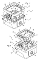
- a sealed electrical apparatus 1 comprising a mounting element formed by a box 10 projecting on any wall (wall or partition), and a lid comprising two separate parts, namely , a frame-shaped plate 20 adjustable on the front face of the box 10, and a hubcap 30 intended to close a central opening 21 delimited internally by the plate 20.
- the electrical switchgear 1 is a switch, but it could be a back and forth, a socket, a pusher emergency stop button, a thermostat or a light.
- the box 10 of the electrical equipment 1 is of parallelepipedal shape, it has four side walls which border a square bottom wall. Two of its side walls vis-à-vis comprise cable entries 19 closed by knockouts.
- the bottom wall of the box 10 carries meanwhile means for mounting a base of the gearing mechanism (not shown), formed here by uprights 18 oriented towards the front face of the box 10.
- the front face of this box 10 is completely open. It is delimited by a peripheral edge 11 (formed by the edge of the free edges of the side walls of the box 10) which has a recess forming, along the peripheral edge 11, a projecting rib 11A ( figure 3 ).
- the plate 20 has a frame shape whose four edges internally delimit a central opening 21.
- This plate 20 is formed by molding a single piece of plastic material. Its four edges have the same section generally U-shaped.
- This peripheral groove 22 houses a seal 41 disposed between the plate 20 and the hubcap 30 (see FIG. figure 4 ). This seal 41 may be overmolded on the rear face of the trim 30 or simply reported in the groove.
- the edge of the other leg of the U, the outer leg 20A is intended to be pressed against the peripheral edge 11 of the box 10. It has a recess which forms a rib 26 projecting from the peripheral edge rib 11A 11 of the box 10, so that the plate 20 can fit on the box 10.
- a peripheral seal 40 is disposed between the plate 20 and the box 10. More particularly, the seal 40 is housed between the edge of the outer branch 20A of the plate 20 and the peripheral edge 11 of the box 10. .
- the seal may be overmoulded or attached either along the edge of the outer leg 20A of the plate 20, or along the peripheral edge 11 of the box 10.
- the plate 20 carries latching means 24 adapted to cooperate in a detachable manner without tools with latching means 12 complementary to the box 10.
- the plate 20 comprise two pairs of latching claws 24 arranged back-to-back on two opposite edges of its central opening 21.
- Each latching claw 24 has a straight body 24A which extends from the edge of the inner branch 20B of the plate 20 in the extension of said branch towards the bottom wall of the box 10, and an end 24B facing towards the outer branch 20A of the plate 20.
- the end 24B of each clawing claw 24 has a flat upper face 24C, that facing the front face of the electrical equipment 1 sealed, which is inclined at an angle greater than 90 degrees relative to the direction in which extends the right body 24A, here equal to about 135 degrees.
- ratchet ribs 12 have lengths equal to the widths of the ratchet claws 24. These ratchet ribs 12 have lower faces 12A facing the bottom wall of the box 10 on which are intended to hook the said ends. 24B of the latching claws 24.
- Each lower face 12A is a flat surface inclined at an angle of about 135 degrees with respect to the wall of the box which carries the corresponding ratcheting rib 12 so that the upper faces 24C ends 24B of the latching claws 24 can slide flat on said lower faces 12A of the ratchet ribs 12 (see Figures 3 and 4 ).
- the opposite side walls of the box 10 carry, below each ratchet rib 12, an L-shaped wall 13 whose long length 13A extends parallel to the bottom wall of the box 10 and whose short length 13B raises towards the front face of the box 10 facing the corresponding ratcheting rib 12.
- a passage housing for one of the latching claws 24 is defined between the short length 13B of each L-shaped wall 13 and the corresponding ratcheting rib 12 (see FIG. figure 3 ).
- each L-shaped wall 13 is reinforced by a reinforcing wall 14 which extends between one of the edges of said L-shaped wall 13 and the side wall of the box 10 which carries it (see FIG. figure 1 ).
- the hubcap 30 is here in the form of a rigid frame whose four edges define a central opening closed by a sealing membrane 39.
- This sealing membrane 39 is here pierced with two orifices 38 for the passage of two legs of a control key (not shown) adapted to be mounted on a rocker switch mechanism (not shown).
- the rear face of the hubcap 30 is, at orifices 38, mostly closed on its surface.
- the hubcap 30 is here formed by molding a single piece of plastic material, the sealing membrane 39 being formed integrally with the hubcap.
- the hubcap 30 comprises on the front face a peripheral rim 36 which, when the embellisher 30 is placed on the box 10, is placed against the outer face (turned towards the central opening 21) of the inner branch. 20B of the plate 20 (see figure 4 ).
- the hubcap 30 bears on its rear face, near its peripheral rim 36, tabs 31 which extend perpendicularly to the plane of the hubcap.
- These lugs 31 of small thickness have a width substantially equal to the length of the ratchet ribs 12 of the box 10. They are adapted to be inserted between said latching means 24 of the plate 20 and a portion 13 of the mounting member 10 of the electrical equipment 1 for, on the one hand, locking said latching means 24 of the plate 20 on the complementary latching means 12 of the mounting element 10 and, on the other hand, cause a pressing force of the plate 20 on the mounting element 10 which compresses said seal 40.
- the hubcap 30 when the hubcap 30 is placed in the central opening 21 of the plate 20 snapped by its latching claws 24 on the ratchet rib 12 of the box 10, the lugs 31 of the hubcap 30 are inserted in said passageways defined between the L-shaped walls 13 and the ratchet ribs 12 of the box 10 to be wedged between the latching claws 24 of the plate 20 and the shortened lengths 13B of said L-shaped walls. 13 (see figure 4 ).
- the tabs 31 of the hubcap 30 and the latching claws 24 of the plate 20 vis-à-vis have contact surfaces inclined relative to each other.
- each lug 31 has substantially straight faces (at the angle of demolding close) parallel to the side wall opposite the box 10.
- the back of the right body 24A of each claw claw 24 has a contact surface 25, intended to come into contact with a face 35 of one of the tabs 31 of the trim 30, which is inclined with respect to the side wall opposite the box 10.
- each lug 31 of the hubcap 30 when each lug 31 of the hubcap 30 is inserted between the latching claw 24 and the short length 13B lifted from the corresponding L-shaped wall, it pushes the claw claw 24 towards the ratchet 12 if although the upper surface 24C plane inclined at 135 degrees of said claw slides on the flat underside 12A of said rib.
- This sliding has the first effect of securely assemble the plate 20 with the box 10 by locking their respective latching means 24,12.
- this sliding faces of these latching means 24, 12 are inclined with respect to the bottom wall of the box 10, this sliding has the second effect of pushing the plate 20 towards the bottom of the box 10 by compressing the seal 40.
- the trim 30 carries laterally and on the front face locking means 32 cooperating with the plate 20 to lock the trim 30 on the plate 20.
- these locking means comprise four quarter-turn keys 32 arranged in pairs on two opposite sides of the hubcap 30.
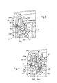
- Each quarter-turn key 32 is housed in the hubcap 30 and is adapted to be pivoted (using a screwdriver) a quarter of a turn in the plane of the hubcap 30 (around an axis normal to the front face of the hubcap) to position its bit 34 protruding from the side face of the hubcap (see figure 6 ).
- Each quarter-turn key 32 has a maneuvering head 33 accessible on the front face of the hubcap 30.
- the peripheral edge 36 of the hubcap 30 comprises at each quarter-turn key 32 a window through which the bit 34 of said key protrudes outwardly of its housing (see Figures 5 and 6 ).
- the plate 20 comprises, in correspondence of quarter-turn keys 32, slots 23 intended to accommodate the keys 34 of said keys 32 which project through the windows of the peripheral rim 36 of the hubcap 30.
- These housings 23 are open only on the side of the central opening 21 of the plate 20, so that the moisture which could possibly infiltrate it can not enter the inside of the box 10.
- the position of these housings 23 is adjusted in height with respect to the peripheral groove 22 so that it is necessary for the bits 34 quarter turn keys 32 can be introduced into these housings 23, d exert a large pressure force of the hubcap 30 on the plate 20.
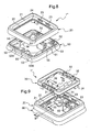
- FIG. 7 there is shown a second embodiment of the electrical equipment 1 'waterproof comprising a mounting member formed by a box 60 to project on a wall, and a cover here comprising three separate parts, namely a plate 70 and two hubcaps 30 reported in two openings 71 of the plate 70.
- the box 60 of the electrical equipment 1 ' can accommodate two equipment mechanisms (not shown) identical or different.
- the box 60 is parallelepiped and has four side walls which border a rectangular bottom wall. Its two large side walls have cable entries 69 closed by knockouts.
- the bottom wall of the box 60 has for its part mounting means of each of the bases of the two equipment mechanisms, formed here by uprights 68 oriented towards the front face of the box 60.
- the front face of this box 60 is completely open and is delimited by a peripheral edge.
- the inner faces of the side walls of the box 60 support ratchet ribs 62 and L-shaped walls 63 identical to the ratchet ribs 12 and the L-shaped walls 13 of the box 10 previously described.
- the plate 70 is in the form of a frame whose rectangular central opening is separated into two identical square openings 71 by a crossmember 77.
- the four edges and the crossmember 77 of the plate 70 have similar U-shaped sections. at the edge section of the plate 20 previously described, so that, on the one hand, each of the two openings 71 of the plate 70 is bordered by a peripheral groove 64 and, on the other hand, the plate 70 is adapted to snap on the peripheral edge of the box 60.
- the plate 70 is also made in one piece by molding a plastic material.
- a peripheral seal 40 is disposed between the peripheral edge of the plate 70 and the peripheral edge of the can 60.
- the plate 70 carries, on the rear face, on each of its peripheral sides, clawing claws 74 projecting adapted to cooperate in a detachable manner without tools with the ratchet ribs 62 of the box 60.
- Its lugs 31 are adapted to fit into the passageways defined between the short lengths of the L-shaped walls 63 and the ratchet ribs 62 of the box 60 to be wedged between the latching claws 74 of the hinged plate 70. on the ratchet ribs 62 and said L-shaped walls 63 so as to lock said ratchet claws 74 on the ratchet ribs 62, and exert a force compressing the seal 40 disposed between the plate 70 and the box 60.
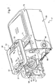
- FIGS. Figures 8 to 10 there is shown a third embodiment of the electrical equipment 1 "sealed comprising a mounting member formed by an equipment support 50 to be projecting on a wall for mounting an equipment mechanism (not shown ) inside a recessed box (not shown) embedded in a wall
- the apparatus support 50 is closed by a cover which comprises the plate 20 and the trim 30 described with reference to FIGS. Figures 1 to 6 relating to the first embodiment of the invention.
- the equipment support 50 is in the form of a planar frame internally defining a central opening 56 adapted to receive the gear mechanism (not shown) which snaps onto the edges of said central opening.
- the rear face of the equipment support 50 is provided with a peripheral seal 57 double lip intended to be applied against the wall, around the opening in the latter.
- the equipment support 50 has on its four sides four through-holes 55 in the shape of a keyhole for attachment to the flush-mounting box by means of fixing screws screwed into chimneys of said flush-mounting box.
- the front face of the equipment support 50 is bordered by a rib 51 on which the plate 20 engages.
- the equipment support 50 comprises on two opposite sides, on the back of the rib 51, two pairs of ratchet ribs 52 on which are intended to hook the latching claws 24 of the plate 20.
- a peripheral seal 40 is disposed between the plate 20 and the equipment support 50. This seal 40 is housed between the edge of the outer branch 20A of the plate 20 and the peripheral edge of the fitting support. 50.
- the seal 40 may be overmolded or attached to either the along the edge of the outer branch 20A of the plate 20, ie along the peripheral edge of the equipment support 50.
- the ratchet ribs 52 of the equipment support 50 have lengths equal to the widths of the ratchet claws 24. These ratchet ribs 52 have inclined flat bottom surfaces 52A on which are intended to engage said ends 24B of the ratchet claws 52. Ratchet claws 24.
- the inclination of the lower face 52A of each ratchet rib 52 is about 135 degrees with respect to the wall of the equipment support which carries the corresponding ratchet rib 52 so that the upper faces 24C inclined ends 24B of the latching claws 24 can slide flat on said lower faces 52A of the ratchet ribs 52.
- the equipment support 50 has, moreover, opposite each of its detent ribs 52, an opening 53 defining with the ratchet rib 52 a passage housing of a latching claw 24 of the plate 20.
- Each opening 53 has a calibrated width and a length equal to the length of the ratchet ribs 52. This calibrated width is such that, when the embellisher 30 is placed in the opening 21 of the plate 20, each tab 31 of the hubcap 30 is supported on one side against the bottom 53A of the opening 53, and, on the other side, against the contact surface 25 of one of the latching claws 24 of the plate 20 so as to lock these claws on the ratchet ribs 52 of the equipment support 50, and exert a pressure force compressing the seal 40.
- the locking of the trim 30 on the plate 20 is achieved by means of quarter-turn keys 32 engaged in the corresponding housing 23 of the plate 20 as described in detail above.
- the seal between the hub cap 30 and the plate 20 is ensured, as in the first embodiment shown in FIGS. Figures 1 to 6 , by a peripheral seal housed in the peripheral groove 22 of the plate 20 and compressed between the latter and said hubcap 30 locked thereon.
Abstract
Description
La présente invention concerne de manière générale les appareillages électriques étanches tels que par exemple les interrupteurs, les va-et-vient et les prises de courant.The present invention relates generally sealed electrical equipment such as for example switches, back and forth and sockets.
Elle concerne plus particulièrement un appareillage électrique étanche comportant un élément de montage d'au moins un mécanisme d'appareillage, un couvercle à rapporter sur l'avant dudit élément de montage et un joint d'étanchéité périphérique interposé entre ledit couvercle et ledit élément de montage.More particularly, it relates to sealed electrical equipment comprising a mounting element of at least one equipment mechanism, a cover to be attached to the front of said mounting element and a peripheral seal interposed between said cover and said mounting element. mounting.
Actuellement, les appareillages électriques étanches sont majoritairement des appareillages à rapporter en saillie d'une paroi quelconque.Currently, sealed electrical equipment is mainly equipment to report projecting from any wall.
Ces appareillages électriques comprennent une boîte ouverte à l'avant, logeant le ou les mécanismes d'appareillage. Cette boîte est fermée par un enjoliveur donnant la fonction dudit appareillage électrique étanche. Cet enjoliveur porte une touche d'actionnement si l'appareillage électrique est un interrupteur ou un va-et-vient, ou présente un puit d'insertion d'une fiche si l'appareillage électrique est une prise de courant.These electrical devices include an open box at the front, housing the equipment or mechanisms. This box is closed by a hubcap giving the function of said sealed electrical equipment. This hubcap carries an actuation key if the electrical equipment is a switch or a back and forth, or has a well for insertion of a plug if the electrical equipment is a socket.
Pour assurer l'étanchéité entre la boîte et l'enjoliveur, un joint d'étanchéité est interposé entre le pourtour de leurs faces en contact. Les moyens de fixation de l'enjoliveur sur la boîte doivent alors être suffisamment robustes pour pouvoir comprimer le joint d'étanchéité afin que ce dernier assure correctement sa fonction.To seal between the box and the hubcap, a seal is interposed between the periphery of their faces in contact. The fastening means of the hubcap on the box must then be strong enough to compress the seal so that it properly performs its function.
Pour cela, ces moyens de fixation comprennent généralement des vis de fixation dont les corps filetés sont insérés au travers d'ouvertures de l'enjoliveur et vissés dans des alésages taraudés de cheminées de la boîte, et dont les têtes prennent appui contre l'enjoliveur.For this, these fixing means generally comprise fixing screws whose threaded bodies are inserted through openings of the hubcap and screwed into threaded bores of chimneys of the box, and whose heads bear against the hubcap .
Les moyens de fixation peuvent comprendre également des moyens d'encliquetage tels que des dents venant se loger dans des ouvertures correspondantes. Cependant, pour que ces moyens d'encliquetage assurent une compression suffisante du joint d'étanchéité, ils doivent être indémontables sans l'aide d'un outil inséré dans une ouverture d'accès.The fastening means may also comprise latching means such as teeth that are housed in corresponding openings. However, for these latching means to provide sufficient compression of the seal, they must be removable without the aid of a tool inserted into an access opening.
Un tel dispositif est décrit dans le document
L'inconvénient principal de tels moyens de fixation par vissage ou par encliquetage est qu'ils nécessitent le perçage d'ouvertures dans l'enjoliveur au travers desquelles peut s'infiltrer de l'humidité.The main disadvantage of such fastening means by screwing or snapping is that they require the drilling of openings in the hubcap through which can infiltrate moisture.
Ainsi, pour qu'un tel appareillage réponde au niveau d'étanchéité requis avec un indice de protection au moins égal à 55, il est nécessaire d'étanchéifier individuellement les ouvertures à l'aide de joints appropriés.Thus, for such an apparatus to meet the required sealing level with a degree of protection of at least 55, it is necessary to seal the openings individually with appropriate seals.
En outre, ce principe de fixation par vissage ou par encliquetage du couvercle (enjoliveur) sur la boîte (pour pose en saillie) ne peut être appliqué directement aux appareillages à encastrer compte tenu de l'absence dans les boîtes d'encastrement actuelles de formes identiques à celles des boîtes pour pose en saillie autorisant le vissage ou l'encliquetage du couvercle.In addition, this principle of fastening by screwing or snap-fitting of the cover (hubcap) on the box (for surface mounting) can not be applied directly to the built-in appliances, given the absence in the current embedding boxes of shapes. identical to those of boxes for projecting installation allowing screwing or snapping of the cover.
Afin de remédier aux inconvénients précités de l'état de la technique, la présente invention propose un appareillage électrique étanche avec un indice de protection au moins égal à 55, de réalisation simple, fiable et peu coûteuse, et pouvant aussi bien être disposé en saillie qu'encastré dans une paroi.In order to overcome the aforementioned drawbacks of the state of the art, the present invention proposes a sealed electrical apparatus with a protection index at least equal to 55, of simple, reliable and inexpensive construction, and which can also be protruding embedded in a wall.
Plus particulièrement, on propose selon l'invention un appareillage électrique étanche tel que défini dans l'introduction, dans lequel le couvercle comprend au moins deux pièces distinctes, à savoir, une plaque se présentant sous la forme d'un cadre qui porte des moyens d'encliquetage adaptés à coopérer de manière démontable sans outils avec des moyens d'encliquetage complémentaires dudit élément de montage, et au moins un enjoliveur définissant la fonction dudit appareillage électrique étanche, à rapporter dans chaque ouverture délimitée intérieurement par ladite plaque, chaque enjoliveur comprenant des pattes adaptées à s'insérer entre lesdits moyens d'encliquetage de la plaque et une partie dudit élément de montage pour, d'une part, verrouiller lesdits moyens d'encliquetage de la plaque sur les moyens d'encliquetage complémentaires de l'élément de montage, et, d'autre part, engendrer un effort de pression de la plaque sur l'élément de montage qui comprime ledit joint d'étanchéité.More particularly, it is proposed according to the invention a sealed electrical equipment as defined in the introduction, wherein the cover comprises at least two separate parts, namely, a plate in the form of a frame which carries means snap-fasteners adapted to detachably cooperate without tools with complementary latching means of said mounting member, and at least one embellisher defining the function of said sealed electrical equipment, to report in each opening delimited internally by said plate, each hubcap comprising tabs adapted to be inserted between said latching means of the plate and a portion of said mounting member for, on the one hand, locking said latching means of the plate on the complementary latching means of the element mounting, and, on the other hand, generating a pressing force of the plate on the mounting element which comp rhyme said seal.
Ainsi, avantageusement, dans l'appareillage électrique selon l'invention, le couvercle, comprenant la plaque et l'enjoliveur, est monté facilement de manière démontable sans outil sur l'élément de montage. En particulier, les moyens d'encliquetage démontables de la plaque, verrouillés par les pattes de l'enjoliveur, permettent à ladite plaque de compresser suffisamment le joint d'étanchéité entre la plaque et l'élément de montage pour assurer une bonne étanchéité.Thus, advantageously, in the electrical equipment according to the invention, the cover, comprising the plate and the hubcap, is easily removably mounted without tools on the mounting element. In particular, the detachable latching means of the plate, locked by the legs of the hubcap, allow said plate to sufficiently compress the seal between the plate and the mounting member to ensure a good seal.
Selon une première caractéristique avantageuse de l'appareillage électrique étanche conforme à l'invention, chaque enjoliveur porte latéralement ou en face avant des moyens de verrouillage coopérant avec la plaque pour verrouiller l'enjoliveur sur la plaque.According to a first advantageous characteristic of the sealed electrical equipment according to the invention, each trim member carries laterally or in front of locking means cooperating with the plate to lock the hubcap on the plate.
Ces moyens de verrouillage assurent le verrouillage de l'enjoliveur sur la plaque, et par là même, un verrouillage supplémentaire des moyens d'encliquetage de la plaque sur les moyens d'encliquetage complémentaires de l'élément de montage, ce qui maintient le joint d'étanchéité sous pression. Par ailleurs, la position de ces moyens de verrouillage évite à la face arrière de l'enjoliveur d'être traversée d'ouvertures pour l'insertion de vis de fixation ou d'outil. L'enjoliveur ne comprend ainsi aucune ouverture au travers de laquelle l'humidité peut passer.These locking means ensure the locking of the hubcap on the plate, and thereby an additional locking of the latching means of the plate on the complementary latching means of the mounting element, which maintains the seal pressure sealing. Moreover, the position of these locking means prevents the rear face of the hubcap from being traversed by openings for the insertion of fixing screws or tools. The hubcap does not include any opening through which moisture can pass.
Selon une autre caractéristique avantageuse de l'appareillage électrique étanche conforme à l'invention, les moyens de verrouillage comportent des clés quart-de-tour dont les têtes sont accessibles en face avant de l'enjoliveur et dont les pannetons sont adaptés à faire saillie des faces latérales de l'enjoliveur pour s'engager dans des logements latéraux de la plaque et prendre appui sur celle-ci.According to another advantageous characteristic of the sealed electrical equipment according to the invention, the locking means comprise quarter-turn keys whose heads are accessible on the front face of the hubcap and whose bits are adapted to protrude side faces of the hubcap to engage in lateral housing of the plate and support it.
Avantageusement, l'appareillage électrique étanche comporte au moins un autre joint d'étanchéité périphérique interposé entre chaque enjoliveur et ladite plaque.Advantageously, the sealed electrical equipment comprises at least one other peripheral seal interposed between each hubcap and said plate.
Préférentiellement, la position et la forme des logements dans la plaque sont ajustées de sorte que ces logements sont adaptés à recevoir de manière étanche les pannetons des clés quart-de-tour de chaque enjoliveur pour que lesdits pannetons engendrent un autre effort de pression de l'enjoliveur sur la plaque qui comprime ledit autre joint d'étanchéité.Preferably, the position and the shape of the housings in the plate are adjusted so that these housings are adapted to receive in a sealed manner the bits of the quarter-turn keys of each hubcap so that said bobs generate another pressure force of embellisher on the plate which compresses said other seal.
Avantageusement, la plaque comporte une gorge périphérique qui borde intérieurement chaque ouverture et qui reçoit chaque autre joint d'étanchéité.Advantageously, the plate has a peripheral groove which borders each opening internally and which receives each other seal.
Préférentiellement, chaque autre joint d'étanchéité est rapporté ou surmoulé sur l'enjoliveur correspondant.Preferably, each other seal is attached or overmolded on the corresponding hubcap.
Selon une autre caractéristique avantageuse de l'appareillage électrique étanche conforme à l'invention, les pattes de l'enjoliveur et les moyens d'encliquetage de la plaque présentent des surfaces de contact inclinées l'une par rapport à l'autre permettant, lorsqu'elles viennent au contact l'une de l'autre, d'une part, de pousser lesdits moyens d'encliquetage de la plaque vers les moyens d'encliquetage complémentaires de l'élément de montage de manière à les verrouiller ensemble, et, d'autre part, d'engendrer ledit effort de pression de la plaque sur l'élément de montage pour comprimer ledit joint d'étanchéité.According to another advantageous characteristic of the sealed electrical equipment according to the invention, the lugs of the hubcap and the means latching the plate have contact surfaces inclined with respect to each other, when they come into contact with one another, on the one hand, to push said latching means of the plate towards the complementary latching means of the mounting element so as to lock them together, and, secondly, to generate said pressure force of the plate on the mounting element to compress said gasket. sealing.
Bien entendu, en variante, on pourrait prévoir que ce soient les surfaces de contact des pattes de l'enjoliveur et de la partie rigide de l'élément de montage qui soient inclinées. Ces surfaces de contact engendreraient des efforts sensiblement identiques à ceux précédemment décrits et ayant les mêmes effets.Of course, alternatively, it could be provided that the contact surfaces of the lugs of the hubcap and the rigid portion of the mounting member are inclined. These contact surfaces would generate efforts substantially identical to those previously described and having the same effects.
Préférentiellement, les moyens d'encliquetage de la plaque sont des griffes d'encliquetage présentant chacune une extrémité orientée à 135 degrés par rapport au corps droit de ladite griffe et adaptées à s'accrocher sur des nervures d'encliquetage présentant une pente de réception de même inclinaison, et lesdites surfaces de contact des moyens d'encliquetage sont prévues au dos des griffes d'encliquetage.Preferably, the latching means of the plate are snap claws each having an end oriented at 135 degrees with respect to the right body of said claw and adapted to catch on snap ribs having a receiving slope of same inclination, and said contact surfaces of the detent means are provided on the back of the latching claws.
Ainsi, l'inclinaison des griffes et desdites nervures rend l'encliquetage non verrouillé désencliquetable par un simple effort de traction exercé sur la plaque.Thus, the inclination of the claws and said ribs makes the latch unlocked unlockable by a simple traction force exerted on the plate.
D'autres caractéristiques avantageuses et non limitatives de l'appareillage électrique étanche selon l'invention sont les suivantes :
- lesdites surfaces de contact des pattes de l'enjoliveur s'étendent parallèlement au corps droit des griffes d'encliquetage et lesdites surfaces de contact des griffes d'encliquetage sont inclinées par rapport audit corps droit ;
- ledit joint d'étanchéité est rapporté ou surmoulé sur l'élément de montage;
- ledit joint d'étanchéité est rapporté ou surmoulé sur le cadre ; et
- la plaque et l'enjoliveur sont chacun formés d'une seule pièce par moulage d'une matière plastique.
- said contact surfaces of the lugs of the hubcap extend parallel to the right body of the ratchet claws and said contact surfaces of the ratchet claws are inclined with respect to said right body;
- said seal is attached or overmolded on the mounting member;
- said seal is attached or overmoulded on the frame; and
- the plate and the hubcap are each formed in one piece by molding a plastic material.
Selon un premier mode de réalisation de l'appareillage électrique étanche conforme à l'invention, l'élément de montage est une boîte à rapporter en saillie sur une paroi.According to a first embodiment of the sealed electrical equipment according to the invention, the mounting element is a projecting box to project on a wall.
Selon un autre mode de réalisation de l'appareillage électrique étanche conforme à l'invention, l'élément de montage est un support d'appareillage pour le montage encastré du mécanisme d'appareillage à l'intérieur d'une boîte d'encastrement.According to another embodiment of the sealed electrical equipment according to the invention, the mounting element is an equipment support for the flush mounting of the switchgear mechanism inside a flush-mounting box.
La description qui va suivre en regard des dessins annexés, donnés à titre d'exemples non limitatifs, fera bien comprendre en quoi consiste l'invention et comment elle peut être réalisée.The following description with reference to the accompanying drawings, given as non-limiting examples, will make it clear what the invention consists of and how it can be achieved.
Sur les dessins annexés :
- la
figure 1 est une vue schématique éclatée en perspective d'une boîte en saillie et d'une plaque d'un premier mode de réalisation d'un appareillage électrique étanche selon l'invention ; - la
figure 2 est une vue schématique éclatée en perspective de la boîte en saillie, de la plaque et d'un enjoliveur de l'appareillage électrique étanche de lafigure 1 ; - la
figure 3 est une vue en coupe selon le plan A-A de lafigure 1 ; - les
figures 4 et5 sont des vues de détail en coupe selon le plan A-A et le plan A1- A1 de l'appareillage électrique étanche de lafigure 2 assemblé ; - la
figure 6 est une vue schématique de face de l'enjoliveur de lafigure 2 ; - la
figure 7 est une vue schématique en perspective éclatée et en coupe partielle d'un deuxième mode de réalisation de l'appareillage électrique étanche selon l'invention ; - la
figure 8 est une vue schématique éclatée en perspective d'un support d'appareillage et d'une plaque d'un troisième mode de réalisation de l'appareillage électrique étanche selon l'invention ; - la
figure 9 est une vue schématique éclatée en perspective du support d'appareillage, de la plaque et d'un enjoliveur de l'appareillage électrique étanche de lafigure 8 ; et - la
figure 10 est une vue en coupe selon le plan B-B de lafigure 9 .
- the
figure 1 is an exploded schematic perspective view of a projecting box and a plate of a first embodiment of a sealed electrical apparatus according to the invention; - the
figure 2 is an exploded schematic view in perspective of the projecting box, the plate and a hubcap of the sealed electrical equipment of thefigure 1 ; - the
figure 3 is a sectional view according to the plane AA of thefigure 1 ; - the
figures 4 and5 are detailed sectional views along the plane AA and the plane A 1 - A 1 of the sealed electrical equipment of thefigure 2 assembled; - the
figure 6 is a schematic front view of the hubcap of thefigure 2 ; - the
figure 7 is a schematic perspective exploded view and in partial section of a second embodiment of the sealed electrical equipment according to the invention; - the
figure 8 is an exploded schematic perspective view of an apparatus support and a plate of a third embodiment of the sealed electrical equipment according to the invention; - the
figure 9 is an exploded diagrammatic perspective view of the equipment support, the plate and a hubcap of the sealed electrical equipment of thefigure 8 ; and - the
figure 10 is a sectional view along the plane BB of thefigure 9 .
Sur les
Ici, l'appareillage électrique 1 étanche est un interrupteur, mais il pourrait être un va-et-vient, une prise de courant, un poussoir coup-de-poing d'arrêt d'urgence, un thermostat ou encore un voyant lumineux.Here, the
Comme le montrent les
La face avant de cette boîte 10 est complètement ouverte. Elle est délimitée par un bord périphérique 11 (formé par la tranche des bords libres des parois latérales de la boîte 10) qui présente un décrochement formant, le long du bord périphérique 11, une nervure 11A en saillie (
Comme le montrent les
L'une des branches du U, la branche intérieure 20B qui longe l'ouverture 21 centrale de la plaque 20, forme à son extrémité une gorge périphérique 22 qui borde intérieurement l'ouverture 21 centrale. Cette gorge périphérique 22 loge un joint d'étanchéité 41 disposé entre la plaque 20 et l'enjoliveur 30 (voir
La tranche de l'autre branche du U, la branche extérieure 20A est destinée à venir s'appliquer contre le bord périphérique 11 de la boîte 10. Elle présente un décrochement qui forme une nervure 26 en saillie complémentaire de la nervure 11A du bord périphérique 11 de la boîte 10, de sorte que la plaque 20 peut s'emboîter sur la boîte 10.The edge of the other leg of the U, the
Un joint d'étanchéité 40 périphérique est disposé entre la plaque 20 et la boîte 10. Plus particulièrement, le joint d'étanchéité 40 est logé entre la tranche de la branche extérieure 20A de la plaque 20 et le bord périphérique 11 de la boîte 10.A
Le joint d'étanchéité peut être surmoulé ou rapporté soit le long de la tranche de la branche extérieure 20A de la plaque 20, soit le long du bord périphérique 11 de la boîte 10.The seal may be overmoulded or attached either along the edge of the
Selon une caractéristique avantageuse de l'invention, la plaque 20 porte des moyens d'encliquetage 24 adaptés à coopérer de manière démontable sans outils avec des moyens d'encliquetage 12 complémentaires de la boîte 10.According to an advantageous characteristic of the invention, the
Plus précisément, comme le montrent les
Chaque griffe d'encliquetage 24 présente un corps droit 24A qui s'étend depuis la tranche de la branche intérieure 20B de la plaque 20 dans le prolongement de ladite branche vers la paroi de fond de la boîte 10, et une extrémité 24B orientée vers la branche extérieure 20A de la plaque 20. L'extrémité 24B de chaque griffe d'encliquetage 24 présente une face supérieure 24C plane, celle tournée vers la face avant de l'appareillage électrique 1 étanche, qui est inclinée d'un angle supérieur à 90 degrés par rapport à la direction selon laquelle s'étend le corps droit 24A, ici égal à environ 135 degrés.Each latching
En outre, deux parois latérales opposées de la boîte 10 destinées à être disposées en regard des griffes d'encliquetage 24 de la plaque 20 portent des nervures d'encliquetage 12 formant lesdits moyens d'encliquetage complémentaires. Les nervures d'encliquetage 12 présentent des longueurs égales aux largeurs des griffes d'encliquetage 24. Ces nervures d'encliquetage 12 présentent des faces inférieures 12A tournées vers la paroi de fond de la boîte 10 sur lesquelles sont destinées à s'accrocher lesdites extrémités 24B des griffes d'encliquetage 24. Chaque face inférieure 12A est une surface plane inclinée d'un angle d'environ 135 degrés par rapport à la paroi de la boîte qui porte la nervure d'encliquetage 12 correspondante de sorte que les faces supérieures 24C des extrémités 24B des griffes d'encliquetage 24 puissent glisser à plat sur lesdits faces inférieures 12A des nervures d'encliquetage 12 (voir
Comme le montrent plus particulièrement les
Un logement de passage pour une des griffes d'encliquetage 24 est défini entre la petite longueur 13B de chaque paroi en L 13 et la nervure d'encliquetage 12 correspondante (voir
En outre, chaque paroi en L 13 est renforcée par une paroi de renfort 14 qui s'étend entre un des bords de ladite paroi en L 13 et la paroi latérale de la boîte 10 qui la porte (voir
Comme le montrent plus particulièrement les
L'enjoliveur 30 est ici formé par moulage d'une seule pièce en matière plastique, la membrane d'étanchéité 39 étant formée d'une seule pièce avec l'enjoliveur.The
L'enjoliveur 30 comporte en face avant un rebord périphérique 36 qui, lors de la mise en place de l'enjoliveur 30 sur la boîte 10, vient se placer contre la face externe (tournée vers l'ouverture 21 centrale) de la branche intérieure 20B de la plaque 20 (voir
En outre, comme le montrent les
Ces pattes 31 de faible épaisseur présentent une largeur sensiblement égale à la longueur des nervures d'encliquetage 12 de la boîte 10. Elles sont adaptées à s'insérer entre lesdits moyens d'encliquetage 24 de la plaque 20 et une partie 13 de l'élément de montage 10 de l'appareillage électrique 1 pour, d'une part, verrouiller lesdits moyens d'encliquetage 24 de la plaque 20 sur les moyens d'encliquetage 12 complémentaires de l'élément de montage 10 et, d'autre part, engendrer un effort de pression de la plaque 20 sur l'élément de montage 10 qui comprime ledit joint d'étanchéité 40.These
Plus particulièrement, lorsque l'enjoliveur 30 est mis en place dans l'ouverture 21 centrale de la plaque 20 encliquetée par ses griffes d'encliquetage 24 sur les nervure d'encliquetage 12 de la boîte 10, les pattes 31 de l'enjoliveur 30 s'insèrent dans lesdits logements de passage définis entre les parois en L 13 et les nervures d'encliquetage 12 de la boîte 10 pour se coincer entre les griffes d'encliquetage 24 de la plaque 20 et les petites longueurs 13B relevées desdites parois en L 13 (voir
Avantageusement, les pattes 31 de l'enjoliveur 30 et les griffes d'encliquetage 24 de la plaque 20 en vis-à-vis présentent des surfaces de contact inclinées les unes par rapport aux autres.Advantageously, the
Ici, comme le montre la
Ainsi, lorsque chaque patte 31 de l'enjoliveur 30 s'insère entre la griffe d'encliquetage 24 et la petite longueur 13B relevée de la paroi en L correspondante, elle pousse la griffe d'encliquetage 24 vers la nervure d'encliquetage 12 si bien que la face supérieure 24C plane inclinée à 135 degrés de ladite griffe glisse sur la face inférieure 12A plane de ladite nervure. Ce glissement a pour premier effet d'assembler solidement la plaque 20 avec la boîte 10 en verrouillant leurs moyens d'encliquetage 24,12 respectifs. Par ailleurs, les faces de glissement de ces moyens d'encliquetage 24,12 étant inclinées par rapport à la paroi de fond de la boîte 10, ce glissement a pour second effet de pousser la plaque 20 vers le fond de la boîte 10 en comprimant le joint d'étanchéité 40.Thus, when each lug 31 of the
Comme le montrent les
Plus particulièrement, ces moyens de verrouillage comportent quatre clés quart-de-tour 32 disposées par paire sur deux côtés opposés de l'enjoliveur 30. Chaque clé quart-de-tour 32 est logée dans l'enjoliveur 30 et est adaptée à être pivotée (à l'aide d'un tournevis) d'un quart de tour dans le plan de l'enjoliveur 30 (autour d'un axe normal à la face avant de l'enjoliveur) pour positionner son panneton 34 en saillie de la face latérale de l'enjoliveur (voir
La plaque 20 comprend en correspondance des clés quart-de-tour 32 des logements 23destinés à accueillir les pannetons 34 desdites clés 32 qui font saillie au travers des fenêtres du rebord périphérique 36 de l'enjoliveur 30.The
Ces logements 23 ne sont ouverts que du côté de l'ouverture 21 centrale de la plaque 20, de sorte que l'humidité qui pourrait éventuellement s'infiltrer dedans ne puisse pas entrer à l'intérieur de la boîte 10.These
Préférentiellement, la position de ces logements 23 est ajustée en hauteur par rapport à la gorge périphérique 22 de sorte qu'il est nécessaire, pour que les pannetons 34 des clés quart-de-tour 32 puissent s'introduire dans ces logements 23, d'exercer un important effort de pression de l'enjoliveur 30 sur la plaque 20.Preferably, the position of these
Ainsi, lorsque les panetons 34 sont insérés dans ces logements 23, le joint d'étanchéité 41 placé dans la gorge périphérique 22 est correctement comprimé entre la face arrière de l'enjoliveur 30 et la plaque 20, de sorte qu'aucune particule liquide ne peut s'infiltrer entre eux.Thus, when the
Sur la
Selon ce mode de réalisation, la boîte 60 de l'appareillage électrique 1' peut accueillir deux mécanismes d'appareillage (non représentés) identiques ou différents.According to this embodiment, the
La boîte 60 est parallélépipédique et comporte quatre parois latérales qui bordent une paroi de fond rectangulaire. Ses deux grandes parois latérales présentent des entrées de câbles 69 obturées par des opercules défonçables. La paroi de fond de la boîte 60 comporte quant à elle des moyens de montage de chacun des socles des deux mécanismes d'appareillage, formés ici par des montants 68 orientés vers la face avant de la boîte 60.The
La face avant de cette boîte 60 est complètement ouverte et est délimitée par un bord périphérique.The front face of this
Les faces intérieures des parois latérales de la boîte 60 supportent des nervures d'encliquetage 62 et des parois en L 63 identiques aux nervures d'encliquetage 12 et aux parois en L 13 de la boîte 10 précédemment décrite.The inner faces of the side walls of the
La plaque 70 se présente sous la forme d'un cadre dont l'ouverture centrale rectangulaire est séparée en deux ouvertures 71 carrées identiques par une traverse 77. Les quatre bords et la traverse 77 de la plaque 70 présentent des sections en forme de U semblables à la section des bords de la plaque 20 précédemment décrite, si bien que, d'une part, chacune des deux ouvertures 71 de la plaque 70 est bordée par une gorge périphérique 64 et, d'autre part, la plaque 70 est adaptée à s'emboîter sur le bord périphérique de la boîte 60.The
La plaque 70 est également réalisée d'une seule pièce par moulage d'une matière plastique.The
Un joint d'étanchéité 40 périphérique est disposé entre la tranche périphérique de la plaque 70 et le bord périphérique de la boîte 60.A
La plaque 70 porte en face arrière, sur chacun de ses côtés périphériques, des griffes d'encliquetage 74 en saillies adaptées à coopérer de manière démontable sans outils avec les nervures d'encliquetage 62 de la boîte 60.The
Chaque enjoliveur 30, à rapporter dans une ouverture 71 de la plaque 70, est identique à celui précédemment décrit et ne sera donc pas décrit une nouvelle fois.Each trim 30 to report in an
Ses pattes 31 sont adaptées à s'insérer dans les logements de passage définis entre les petites longueurs des parois en L 63 et les nervures d'encliquetage 62 de la boîte 60 pour se coincer entre les griffes d'encliquetage 74 de la plaque 70 accrochées sur les nervures d'encliquetage 62 et lesdites parois en L 63 de manière à verrouiller lesdites griffes d'encliquetage 74 sur les nervures d'encliquetage 62, et à exercer un effort comprimant le joint d'étanchéité 40 disposé entre la plaque 70 et la boîte 60.Its
D'autres joints d'étanchéité (non représentés) sont disposés dans les gorges périphériques 64 longeant lesdites ouvertures 71 et interposés entre la face arrière des enjoliveurs 30 et la plaque 70. Ils sont destinés à être comprimés lorsque les pannetons des clés quart-de-tour 32 des enjoliveurs 30 s'insèrent dans les logements correspondants de la plaque 70 (comme cela a déjà été décrit dans le détail en référence aux
Sur les
Comme le montrent les
Comme le montre la
Le support d'appareillage 50 comporte sur ses quatre côtés quatre ouvertures traversantes 55 en forme de trou de serrure pour sa fixation à la boîte d'encastrement au moyen de vis de fixation vissée dans des cheminées de ladite boîte d'encastrement.The
La face avant du support d'appareillage 50 est bordée par une nervure 51 sur laquelle vient s'emboîter la plaque 20.The front face of the
Comme le montrent plus particulièrement les
Un joint d'étanchéité 40 périphérique est disposé entre la plaque 20 et le support d'appareillage 50. Ce joint d'étanchéité 40 est logé entre la tranche de la branche extérieure 20A de la plaque 20 et le bord périphérique du support d'appareillage 50. Le joint d'étanchéité 40 peut être surmoulé ou rapporté soit le long de la tranche de la branche extérieure 20A de la plaque 20, soit le long du bord périphérique du support d'appareillage 50.A
Les nervures d'encliquetage 52 du support d'appareillage 50 présentent des longueurs égales aux largeurs des griffes d'encliquetage 24. Ces nervures d'encliquetage 52 présentent des faces inférieures 52A planes inclinées sur lesquelles sont destinées à s'accrocher lesdites extrémités 24B des griffes d'encliquetage 24. L'inclinaison de la face inférieure 52A de chaque nervure d'encliquetage 52 est d'environ 135 degrés par rapport à la paroi du support d'appareillage qui porte la nervure d'encliquetage 52 correspondante de sorte que les faces supérieures 24C inclinées des extrémités 24B des griffes d'encliquetage 24 puissent glisser à plat sur lesdits faces inférieures 52A des nervures d'encliquetage 52.The
Le support d'appareillage 50 présente par ailleurs, en regard de chacune de ses nervures d'encliquetage 52, une ouverture 53 définissant avec la nervure d'encliquetage 52 un logement de passage d'une griffe d'encliquetage 24 de la plaque 20. Chaque ouverture 53 présente une largeur calibrée et une longueur égale à la longueur des nervures d'encliquetage 52. Cette largeur calibrée est telle que, lors de la mise en place de l'enjoliveur 30 dans l'ouverture 21 de la plaque 20, chaque patte 31 de l'enjoliveur 30 prend appui, d'un côté, contre le fond 53A de l'ouverture 53, et, de l'autre côté, contre la surface de contact 25 d'une des griffes d'encliquetage 24 de la plaque 20 de manière à verrouiller ces griffes sur les nervures d'encliquetage 52 du support d'appareillage 50, et à exercer un effort de pression comprimant le joint d'étanchéité 40.The
Le verrouillage de l'enjoliveur 30 sur la plaque 20 est réalisé au moyen des clés quart-de-tour 32 engagées dans les logements 23 correspondants de la plaque 20 comme cela a été décrit dans le détail précédemment.The locking of the trim 30 on the
L'étanchéité entre l'enjoliveur 30 et la plaque 20 est assurée, comme dans le premier mode de réalisation représenté sur les
La présente invention n'est nullement limitée aux modes de réalisation décrits et représentés, mais l'homme du métier saura y apporter toute variante conforme à son esprit.The present invention is not limited to the embodiments described and shown, but the skilled person will be able to make any variant within his mind.
Claims (15)
- Sealed electrical equipment (1) including a mounting element (10; 50; 60) for mounting at least one equipment mechanism, a cover (20, 30; 70) for putting on the front of said mounting element (10; 50; 60), and a peripheral sealing gasket (40) interposed between said cover (20, 30; 70) and said mounting element (10; 50; 60), the cover (20, 30; 70) comprising a plate (20; 70) in the form of a frame that carries snap-fastener means (24; 74) adapted to co-operate, in a manner that can be separated without tools, with complementary snap-fastening means (12; 52; 62) of said mounting element (10; 50; 60), the equipment being characterized in that the cover (20, 30; 70) includes at least two distinct parts, including at least one trim (30) defining the function of said sealed electrical equipment (1) for fitting in each opening (21) defined internally by said plate (20; 70), each trim (30) including tabs (31) suitable for inserting between said snap-fastener means (24; 74) of the plate (20; 70) and a portion (13B; 53A; 63) of said mounting element (10; 50; 60) firstly to lock said snap-fastener means (24) of the plate (20; 70) on the complementary snap-fastener means (12; 52; 62) of the mounting element (10; 50; 60), and secondly to generate a pressure force from the plate (20; 70) against the mounting element (10; 50; 60), thereby compressing said sealing gasket (40).
- Sealed electrical equipment (1) according to the preceding claim, characterized in that each trim (30) carries locking means (32) on its side or its front face for co-operating with the plate (20; 70) in order to lock the trim (30) on the plate (20; 70).
- Sealed electrical equipment (1) according to the preceding claim, characterized in that the locking means include quarter-turn keys (32) having heads (33) that are accessible from the front face of the trim (30) and having key-bits (34) that are adapted to project from the side faces of the trim (30) to engage in side housings (23) in the plate (20; 70) and bear thereagainst.
- Sealed electrical equipment (1) according to any preceding claim, characterized in that it includes at least one other peripheral sealing gasket (41) interposed between each trim (30) and said plate (20; 70).
- Sealed electrical equipment (1) according to either one of the two preceding claims, characterized in that the position and the shape of the housings (23) in the plate (20; 70) are adjusted in such a manner that the housings (23) are adapted to receive the key-bits (34) of the quarter-turn keys (32) of each trim (30) in sealed manner so that said key-bits (34) generate another pressure force from the trim (30) on the plate (20; 70), thereby compressing said other sealing gasket (41).
- Sealed electrical equipment (1) according to any one of the two preceding claims, characterized in that the plate (20; 70) includes a peripheral groove (22) internally adjacent to each opening (21) and receiving each other sealing gasket (41).
- Sealed electrical equipment (1) according to any one of the three preceding claims, characterized in that each other sealing gasket (41) is fitted on or overmolded on the corresponding trim (30).
- Sealed electrical equipment (1) according to any preceding claim, characterized in that the tabs (31) of the trim (30) and the snap-fastener means (24) of the plate (20; 70) present contact surfaces (35, 25; 75) that are inclined relative to one another making it possible, when they come into contact with each other, firstly to push said snap-fastener means (24; 74) of the plate (20; 70) towards the complementary snap-fastener means (12; 52) of the mounting element (10; 50; 60) in such a manner as to lock them together, and secondly to generate said pressure force from the plate (20; 70) against the mounting element (10; 50; 60) in order to compress said sealing gasket (40).
- Sealed electrical equipment (1) according to the preceding claim, characterized in that the snap-fastener means of the plate (20; 70) are snap-fastener claws (24; 74) presenting ends (24B) oriented at 135 degrees and adapted to catch on snap-fastener ribs (12; 52; 62) presenting reception slopes (12A; 52A) having the same inclination, and said contact surfaces (25; 75) of the snap-fastener means are provided on the backs of the snap-fastener claws (24; 74).
- Sealed electrical equipment (1) according to the preceding claim, characterized in that said contact surfaces (35) of the tabs (31) of the trim (30) extend parallel to the straight bodies (24A) of the snap-fastener claws (24; 74), and said contact surfaces (25; 75) of the snap-fastener claws (24; 74) are inclined relative to said straight bodies (24A).
- Sealed electrical equipment (1) according to any preceding claim, characterized in that said sealing gasket (40) is fitted on or overmolded on the mounting element (10; 50; 60).
- Sealed electrical equipment (1) according to any one of claims 1 to 10, characterized in that said sealing gasket (40) is fitted on or overmolded on the plate (20; 70).
- Sealed electrical equipment (1) according to any preceding claim, characterized in that the plate (20; 70)
and the trim (30) are each formed as one-piece moldings of plastics material. - Sealed electrical equipment (1) according to any preceding claim, characterized in that the mounting element is a box (10) for surface mounting on a wall.
- Sealed electrical equipment (1) according to any one of claims 1 to 13, characterized in that the mounting element is an equipment support (50) for flush-mounting the equipment mechanism inside a flush-mounted box.
Applications Claiming Priority (1)
| Application Number | Priority Date | Filing Date | Title |
|---|---|---|---|
| FR0604546A FR2901451B1 (en) | 2006-05-22 | 2006-05-22 | WATERPROOF ELECTRICAL EQUIPMENT TO ARRANGE OR FIT IN A WALL |
Publications (2)
| Publication Number | Publication Date |
|---|---|
| EP1860748A1 EP1860748A1 (en) | 2007-11-28 |
| EP1860748B1 true EP1860748B1 (en) | 2011-10-26 |
Family
ID=37672186
Family Applications (1)
| Application Number | Title | Priority Date | Filing Date |
|---|---|---|---|
| EP07290276A Not-in-force EP1860748B1 (en) | 2006-05-22 | 2007-03-05 | Watertight electrical equipment to be disposed projecting or embedded in a wall |
Country Status (5)
| Country | Link |
|---|---|
| EP (1) | EP1860748B1 (en) |
| AT (1) | ATE531107T1 (en) |
| ES (1) | ES2373692T3 (en) |
| FR (1) | FR2901451B1 (en) |
| PT (1) | PT1860748E (en) |
Cited By (1)
| Publication number | Priority date | Publication date | Assignee | Title |
|---|---|---|---|---|
| CN106463926A (en) * | 2014-04-28 | 2017-02-22 | 勒格朗法国公司 | Secured assembly electrical apparatus |
Families Citing this family (20)
| Publication number | Priority date | Publication date | Assignee | Title |
|---|---|---|---|---|
| PT2632001E (en) | 2012-02-22 | 2014-09-22 | Berker Gmbh & Co Kg | Electrical appliance with lid attached in the mounting member |
| DE102013201790B4 (en) * | 2013-02-05 | 2023-06-07 | Robert Bosch Gmbh | Housing with protection device for a wet seal |
| FR3020516B1 (en) * | 2014-04-28 | 2018-01-26 | Legrand France | ELECTRICAL EQUIPMENT TO BE ENGAGED IN AN ELECTRIC BOX WITH ADJUSTABLE ORIENTATION |
| FR3020520B1 (en) * | 2014-04-28 | 2017-12-22 | Legrand France | CONNECTOR FOR ELECTRICAL EQUIPMENT LODGING IN A RECESSED BOX |
| AR098441A1 (en) * | 2014-11-17 | 2016-05-26 | Ambros Rodolfo | ELECTRIC INSULATING BOX WITH TWO OPTIONS OF HERMETICITY DEGREES FOR ELECTRICITY, COMPUTER AND / OR TELEPHONY |
| DE102016104140A1 (en) * | 2016-03-08 | 2017-09-14 | Auto-Kabel Management Gmbh | Housing with cover for cable lug |
| FR3069386B1 (en) * | 2017-07-21 | 2019-08-23 | Legrand France | CLAMPING ELEMENT FOR ELECTRICAL EQUIPMENT |
| EP3753078A1 (en) | 2018-02-14 | 2020-12-23 | Mtd Products Inc. | Sealing system for electronics enclosure |
| BE1027430B1 (en) * | 2019-07-16 | 2021-02-15 | Niko Nv | MOUNTING SYSTEM FOR AN ELECTRICAL OR ELECTRONIC DEVICE |
| FR3105558B1 (en) * | 2019-12-20 | 2021-12-31 | Legrand France | Electrical box to be fixed projecting from a support |
| FR3105616B1 (en) * | 2019-12-20 | 2022-04-08 | Legrand France | Electrical equipment |
| FR3105562B1 (en) * | 2019-12-20 | 2022-01-07 | Legrand France | Trim and electrical switch comprising such a trim |
| FR3105560B1 (en) * | 2019-12-20 | 2022-03-04 | Legrand France | Waterproof electrical switch |
| FR3105559B1 (en) * | 2019-12-20 | 2023-04-21 | Legrand France | Electrical box and associated electrical equipment |
| FR3105557B1 (en) * | 2019-12-20 | 2022-03-18 | Legrand France | Waterproof electrical switch |
| FR3105622B1 (en) * | 2019-12-20 | 2022-05-06 | Legrand France | Sealed cable entry end, electrical box comprising such an end and electrical equipment comprising a fitting mechanism attached to such an electrical box |
| FR3105561B1 (en) * | 2019-12-20 | 2021-12-31 | Legrand France | Two-piece electrical box |
| FR3105623B1 (en) * | 2019-12-20 | 2022-05-06 | Legrand France | Sealed cable entry end, electrical box comprising such a cable entry end and electrical equipment comprising a fitting mechanism attached to such an electrical box |
| FR3105621B1 (en) * | 2019-12-20 | 2022-08-12 | Legrand France | Electrical box with gasket |
| FR3105624B1 (en) | 2019-12-20 | 2022-01-07 | Legrand France | Waterproof electrical equipment |
Family Cites Families (3)
| Publication number | Priority date | Publication date | Assignee | Title |
|---|---|---|---|---|
| CH526711A (en) * | 1971-06-17 | 1972-08-15 | Siemens Ag Albis | Device for attaching a cover to an apparatus housing body |
| DE9110236U1 (en) * | 1991-08-19 | 1991-12-19 | Hans-Joachim Bernstein Compact-Gehaeuse Gmbh, 4955 Hille, De | |
| JPH11215647A (en) * | 1998-01-28 | 1999-08-06 | Furukawa Electric Co Ltd:The | Electrical junction box |
-
2006
- 2006-05-22 FR FR0604546A patent/FR2901451B1/en not_active Expired - Fee Related
-
2007
- 2007-03-05 PT PT07290276T patent/PT1860748E/en unknown
- 2007-03-05 EP EP07290276A patent/EP1860748B1/en not_active Not-in-force
- 2007-03-05 AT AT07290276T patent/ATE531107T1/en not_active IP Right Cessation
- 2007-03-05 ES ES07290276T patent/ES2373692T3/en active Active
Cited By (2)
| Publication number | Priority date | Publication date | Assignee | Title |
|---|---|---|---|---|
| CN106463926A (en) * | 2014-04-28 | 2017-02-22 | 勒格朗法国公司 | Secured assembly electrical apparatus |
| CN106463926B (en) * | 2014-04-28 | 2019-02-22 | 勒格朗法国公司 | The electrical equipment of safety assembled |
Also Published As
| Publication number | Publication date |
|---|---|
| FR2901451B1 (en) | 2008-07-18 |
| ATE531107T1 (en) | 2011-11-15 |
| FR2901451A1 (en) | 2007-11-23 |
| ES2373692T3 (en) | 2012-02-07 |
| EP1860748A1 (en) | 2007-11-28 |
| PT1860748E (en) | 2012-01-09 |
Similar Documents
| Publication | Publication Date | Title |
|---|---|---|
| EP1860748B1 (en) | Watertight electrical equipment to be disposed projecting or embedded in a wall | |
| FR3000310A1 (en) | ELECTRICAL EQUIPMENT MODULE | |
| FR3000308A1 (en) | REMOVABLE ELECTRICAL EQUIPMENT MODULE, ELECTRIC BOX HAVING SUCH AN APPARATUS MODULE, AND METHOD OF REPLACING SUCH A MODULE OF APPARATUS | |
| EP0755638A1 (en) | Box with rotating lid having a hinge made of flexible tabs | |
| EP1149447B1 (en) | Apparatus support, in particular for electrical apparatus, and box comprising such an apparatus support | |
| WO2015166161A2 (en) | Module of electrical equipment to be snap-fitted into an electrical box | |
| FR3013914A1 (en) | APPARATUS SUPPORT COMPRISING A FIXING ACCESSORY FOR FASTENING TO A WALLBOX, ACCESSORY OF GRIFFING, GRIFFING ASSEMBLY AND ELECTRICAL EQUIPMENT THEREFOR | |
| EP1744427B1 (en) | Cabinet for electrical apparatus with adjustable depth | |
| EP1071183B1 (en) | Support for an electrical apparatus to be mounted on a duct | |
| EP4078746A1 (en) | Sealed cable gland, electrical housing comprising such a cable gland and electrical appliance comprising an appliance mechanism mounted in such an electrical housing | |
| FR2658009A1 (en) | RECESS BOX WITH SIDE EXTENSION, IN PARTICULAR FOR ELECTRICAL APPLIANCE. | |
| FR2888682A1 (en) | VARIABLE LENGTH ACCESSORY FOR ELECTRIC CHUTE AND ELECTRICAL ASSEMBLY COMPRISING AN ELECTRICAL CHUTE AND AN ACCESSORY | |
| EP1744426B1 (en) | Electrical box comprising two elements fixed together by means of a toothed strap | |
| EP3840000B1 (en) | Waterproof electrical switch | |
| EP3840151B1 (en) | Electrical box and associated electrical equipment | |
| FR2957725A1 (en) | ELECTRIC DISTRIBUTION BOX OR BOARD COMPRISING A REMOVABLE ELECTRICAL DEVICE MOUNTING RAIL | |
| EP3121915A1 (en) | Switchgear and electric box for installation in a wall | |
| EP0848470B1 (en) | Electrical distribution raceway and use | |
| EP1376772A1 (en) | Electrical socket with socket shutter and range comprising such a socket | |
| FR3105621A1 (en) | Electrical box fitted with a seal | |
| EP1351359A1 (en) | Apparatus holder for cable channel with access to electrical connecting clamps | |
| FR2781616A1 (en) | Electrical equipment box that can be placed in tandem with another box, with removable panels of different widths | |
| EP2320532B1 (en) | Device for installing a frame upright on the bottom of an electric box and electric box including such a device | |
| EP4109689A1 (en) | Electrical cabinet comprising an electrically insulating element | |
| FR2917907A1 (en) | SHOCK-RESISTANT ELECTRICAL EQUIPMENT IN FRONT PANEL |
Legal Events
| Date | Code | Title | Description |
|---|---|---|---|
| PUAI | Public reference made under article 153(3) epc to a published international application that has entered the european phase |
Free format text: ORIGINAL CODE: 0009012 |
|
| AK | Designated contracting states |
Kind code of ref document: A1 Designated state(s): AT BE BG CH CY CZ DE DK EE ES FI FR GB GR HU IE IS IT LI LT LU LV MC MT NL PL PT RO SE SI SK TR |
|
| AX | Request for extension of the european patent |
Extension state: AL BA HR MK YU |
|
| 17P | Request for examination filed |
Effective date: 20080220 |
|
| 17Q | First examination report despatched |
Effective date: 20080328 |
|
| AKX | Designation fees paid |
Designated state(s): AT BE BG CH CY CZ DE DK EE ES FI FR GB GR HU IE IS IT LI LT LU LV MC MT NL PL PT RO SE SI SK TR |
|
| GRAP | Despatch of communication of intention to grant a patent |
Free format text: ORIGINAL CODE: EPIDOSNIGR1 |
|
| GRAS | Grant fee paid |
Free format text: ORIGINAL CODE: EPIDOSNIGR3 |
|
| GRAA | (expected) grant |
Free format text: ORIGINAL CODE: 0009210 |
|
| AK | Designated contracting states |
Kind code of ref document: B1 Designated state(s): AT BE BG CH CY CZ DE DK EE ES FI FR GB GR HU IE IS IT LI LT LU LV MC MT NL PL PT RO SE SI SK TR |
|
| REG | Reference to a national code |
Ref country code: GB Ref legal event code: FG4D Free format text: NOT ENGLISH |
|
| REG | Reference to a national code |
Ref country code: CH Ref legal event code: EP |
|
| REG | Reference to a national code |
Ref country code: IE Ref legal event code: FG4D |
|
| REG | Reference to a national code |
Ref country code: PT Ref legal event code: SC4A Free format text: AVAILABILITY OF NATIONAL TRANSLATION Effective date: 20111221 |
|
| REG | Reference to a national code |
Ref country code: DE Ref legal event code: R096 Ref document number: 602007018171 Country of ref document: DE Effective date: 20120126 |
|
| REG | Reference to a national code |
Ref country code: ES Ref legal event code: FG2A Ref document number: 2373692 Country of ref document: ES Kind code of ref document: T3 Effective date: 20120207 |
|
| REG | Reference to a national code |
Ref country code: NL Ref legal event code: VDEP Effective date: 20111026 |
|
| LTIE | Lt: invalidation of european patent or patent extension |
Effective date: 20111026 |
|
| REG | Reference to a national code |
Ref country code: AT Ref legal event code: MK05 Ref document number: 531107 Country of ref document: AT Kind code of ref document: T Effective date: 20111026 |
|
| PG25 | Lapsed in a contracting state [announced via postgrant information from national office to epo] |
Ref country code: IS Free format text: LAPSE BECAUSE OF FAILURE TO SUBMIT A TRANSLATION OF THE DESCRIPTION OR TO PAY THE FEE WITHIN THE PRESCRIBED TIME-LIMIT Effective date: 20120226 Ref country code: LT Free format text: LAPSE BECAUSE OF FAILURE TO SUBMIT A TRANSLATION OF THE DESCRIPTION OR TO PAY THE FEE WITHIN THE PRESCRIBED TIME-LIMIT Effective date: 20111026 |
|
| PG25 | Lapsed in a contracting state [announced via postgrant information from national office to epo] |
Ref country code: SE Free format text: LAPSE BECAUSE OF FAILURE TO SUBMIT A TRANSLATION OF THE DESCRIPTION OR TO PAY THE FEE WITHIN THE PRESCRIBED TIME-LIMIT Effective date: 20111026 Ref country code: SI Free format text: LAPSE BECAUSE OF FAILURE TO SUBMIT A TRANSLATION OF THE DESCRIPTION OR TO PAY THE FEE WITHIN THE PRESCRIBED TIME-LIMIT Effective date: 20111026 Ref country code: GR Free format text: LAPSE BECAUSE OF FAILURE TO SUBMIT A TRANSLATION OF THE DESCRIPTION OR TO PAY THE FEE WITHIN THE PRESCRIBED TIME-LIMIT Effective date: 20120127 Ref country code: LV Free format text: LAPSE BECAUSE OF FAILURE TO SUBMIT A TRANSLATION OF THE DESCRIPTION OR TO PAY THE FEE WITHIN THE PRESCRIBED TIME-LIMIT Effective date: 20111026 Ref country code: PL Free format text: LAPSE BECAUSE OF FAILURE TO SUBMIT A TRANSLATION OF THE DESCRIPTION OR TO PAY THE FEE WITHIN THE PRESCRIBED TIME-LIMIT Effective date: 20111026 Ref country code: NL Free format text: LAPSE BECAUSE OF FAILURE TO SUBMIT A TRANSLATION OF THE DESCRIPTION OR TO PAY THE FEE WITHIN THE PRESCRIBED TIME-LIMIT Effective date: 20111026 |
|
| REG | Reference to a national code |
Ref country code: IE Ref legal event code: FD4D |
|
| PG25 | Lapsed in a contracting state [announced via postgrant information from national office to epo] |
Ref country code: CY Free format text: LAPSE BECAUSE OF FAILURE TO SUBMIT A TRANSLATION OF THE DESCRIPTION OR TO PAY THE FEE WITHIN THE PRESCRIBED TIME-LIMIT Effective date: 20111026 |
|
| PG25 | Lapsed in a contracting state [announced via postgrant information from national office to epo] |
Ref country code: CZ Free format text: LAPSE BECAUSE OF FAILURE TO SUBMIT A TRANSLATION OF THE DESCRIPTION OR TO PAY THE FEE WITHIN THE PRESCRIBED TIME-LIMIT Effective date: 20111026 Ref country code: BG Free format text: LAPSE BECAUSE OF FAILURE TO SUBMIT A TRANSLATION OF THE DESCRIPTION OR TO PAY THE FEE WITHIN THE PRESCRIBED TIME-LIMIT Effective date: 20120126 Ref country code: IE Free format text: LAPSE BECAUSE OF FAILURE TO SUBMIT A TRANSLATION OF THE DESCRIPTION OR TO PAY THE FEE WITHIN THE PRESCRIBED TIME-LIMIT Effective date: 20111026 Ref country code: DK Free format text: LAPSE BECAUSE OF FAILURE TO SUBMIT A TRANSLATION OF THE DESCRIPTION OR TO PAY THE FEE WITHIN THE PRESCRIBED TIME-LIMIT Effective date: 20111026 Ref country code: SK Free format text: LAPSE BECAUSE OF FAILURE TO SUBMIT A TRANSLATION OF THE DESCRIPTION OR TO PAY THE FEE WITHIN THE PRESCRIBED TIME-LIMIT Effective date: 20111026 Ref country code: EE Free format text: LAPSE BECAUSE OF FAILURE TO SUBMIT A TRANSLATION OF THE DESCRIPTION OR TO PAY THE FEE WITHIN THE PRESCRIBED TIME-LIMIT Effective date: 20111026 |
|
| PG25 | Lapsed in a contracting state [announced via postgrant information from national office to epo] |
Ref country code: RO Free format text: LAPSE BECAUSE OF FAILURE TO SUBMIT A TRANSLATION OF THE DESCRIPTION OR TO PAY THE FEE WITHIN THE PRESCRIBED TIME-LIMIT Effective date: 20111026 Ref country code: IT Free format text: LAPSE BECAUSE OF FAILURE TO SUBMIT A TRANSLATION OF THE DESCRIPTION OR TO PAY THE FEE WITHIN THE PRESCRIBED TIME-LIMIT Effective date: 20111026 |
|
| PLBE | No opposition filed within time limit |
Free format text: ORIGINAL CODE: 0009261 |
|
| STAA | Information on the status of an ep patent application or granted ep patent |
Free format text: STATUS: NO OPPOSITION FILED WITHIN TIME LIMIT |
|
| BERE | Be: lapsed |
Owner name: LEGRAND SNC Effective date: 20120331 Owner name: LEGRAND FRANCE Effective date: 20120331 |
|
| 26N | No opposition filed |
Effective date: 20120727 |
|
| PG25 | Lapsed in a contracting state [announced via postgrant information from national office to epo] |
Ref country code: MC Free format text: LAPSE BECAUSE OF NON-PAYMENT OF DUE FEES Effective date: 20120331 |
|
| REG | Reference to a national code |
Ref country code: CH Ref legal event code: PL |
|
| GBPC | Gb: european patent ceased through non-payment of renewal fee |
Effective date: 20120305 |
|
| REG | Reference to a national code |
Ref country code: DE Ref legal event code: R097 Ref document number: 602007018171 Country of ref document: DE Effective date: 20120727 |
|
| PG25 | Lapsed in a contracting state [announced via postgrant information from national office to epo] |
Ref country code: CH Free format text: LAPSE BECAUSE OF NON-PAYMENT OF DUE FEES Effective date: 20120331 Ref country code: GB Free format text: LAPSE BECAUSE OF NON-PAYMENT OF DUE FEES Effective date: 20120305 Ref country code: LI Free format text: LAPSE BECAUSE OF NON-PAYMENT OF DUE FEES Effective date: 20120331 Ref country code: BE Free format text: LAPSE BECAUSE OF NON-PAYMENT OF DUE FEES Effective date: 20120331 Ref country code: AT Free format text: LAPSE BECAUSE OF FAILURE TO SUBMIT A TRANSLATION OF THE DESCRIPTION OR TO PAY THE FEE WITHIN THE PRESCRIBED TIME-LIMIT Effective date: 20111026 |
|
| PG25 | Lapsed in a contracting state [announced via postgrant information from national office to epo] |
Ref country code: FI Free format text: LAPSE BECAUSE OF FAILURE TO SUBMIT A TRANSLATION OF THE DESCRIPTION OR TO PAY THE FEE WITHIN THE PRESCRIBED TIME-LIMIT Effective date: 20111026 |
|
| PG25 | Lapsed in a contracting state [announced via postgrant information from national office to epo] |
Ref country code: MT Free format text: LAPSE BECAUSE OF FAILURE TO SUBMIT A TRANSLATION OF THE DESCRIPTION OR TO PAY THE FEE WITHIN THE PRESCRIBED TIME-LIMIT Effective date: 20111026 |
|
| PG25 | Lapsed in a contracting state [announced via postgrant information from national office to epo] |
Ref country code: LU Free format text: LAPSE BECAUSE OF NON-PAYMENT OF DUE FEES Effective date: 20120305 |
|
| PG25 | Lapsed in a contracting state [announced via postgrant information from national office to epo] |
Ref country code: HU Free format text: LAPSE BECAUSE OF FAILURE TO SUBMIT A TRANSLATION OF THE DESCRIPTION OR TO PAY THE FEE WITHIN THE PRESCRIBED TIME-LIMIT Effective date: 20070305 |
|
| PGFP | Annual fee paid to national office [announced via postgrant information from national office to epo] |
Ref country code: TR Payment date: 20150304 Year of fee payment: 9 |
|
| REG | Reference to a national code |
Ref country code: FR Ref legal event code: PLFP Year of fee payment: 10 |
|
| REG | Reference to a national code |
Ref country code: FR Ref legal event code: PLFP Year of fee payment: 11 |
|
| REG | Reference to a national code |
Ref country code: FR Ref legal event code: PLFP Year of fee payment: 12 |
|
| PGFP | Annual fee paid to national office [announced via postgrant information from national office to epo] |
Ref country code: PT Payment date: 20200302 Year of fee payment: 14 |
|
| PGFP | Annual fee paid to national office [announced via postgrant information from national office to epo] |
Ref country code: ES Payment date: 20200401 Year of fee payment: 14 Ref country code: FR Payment date: 20200331 Year of fee payment: 14 Ref country code: DE Payment date: 20200525 Year of fee payment: 14 |
|
| REG | Reference to a national code |
Ref country code: DE Ref legal event code: R119 Ref document number: 602007018171 Country of ref document: DE |
|
| PG25 | Lapsed in a contracting state [announced via postgrant information from national office to epo] |
Ref country code: PT Free format text: LAPSE BECAUSE OF NON-PAYMENT OF DUE FEES Effective date: 20210906 |
|
| PG25 | Lapsed in a contracting state [announced via postgrant information from national office to epo] |
Ref country code: FR Free format text: LAPSE BECAUSE OF NON-PAYMENT OF DUE FEES Effective date: 20210331 Ref country code: DE Free format text: LAPSE BECAUSE OF NON-PAYMENT OF DUE FEES Effective date: 20211001 |
|
| REG | Reference to a national code |
Ref country code: ES Ref legal event code: FD2A Effective date: 20220523 |
|
| PG25 | Lapsed in a contracting state [announced via postgrant information from national office to epo] |
Ref country code: TR Free format text: LAPSE BECAUSE OF NON-PAYMENT OF DUE FEES Effective date: 20160305 |
|
| PG25 | Lapsed in a contracting state [announced via postgrant information from national office to epo] |
Ref country code: ES Free format text: LAPSE BECAUSE OF NON-PAYMENT OF DUE FEES Effective date: 20210306 |